

Page 1
1 TFP
4 mounting brackets
4 hanging straps
2 oval collar connections
4 8/32” X 3/4” sheet metal screws
8 8/32” X 3/8” sheet metal screws
4 pieces of mounting foam
1 set of installation \ operating instructions
1 warranty card
1 wiring diagram
The TFP is equipped with a standard power supply,
on a 5’ 5” cable. Lighted ON/OFF switch.
Materials Supplied
Electrical
* LEAVE FOR HOMEOWNER
NOTE: Due to ongoing research and product development, specifications,
ratings and dimensions are subject to change without notice.
TFP-06
0204
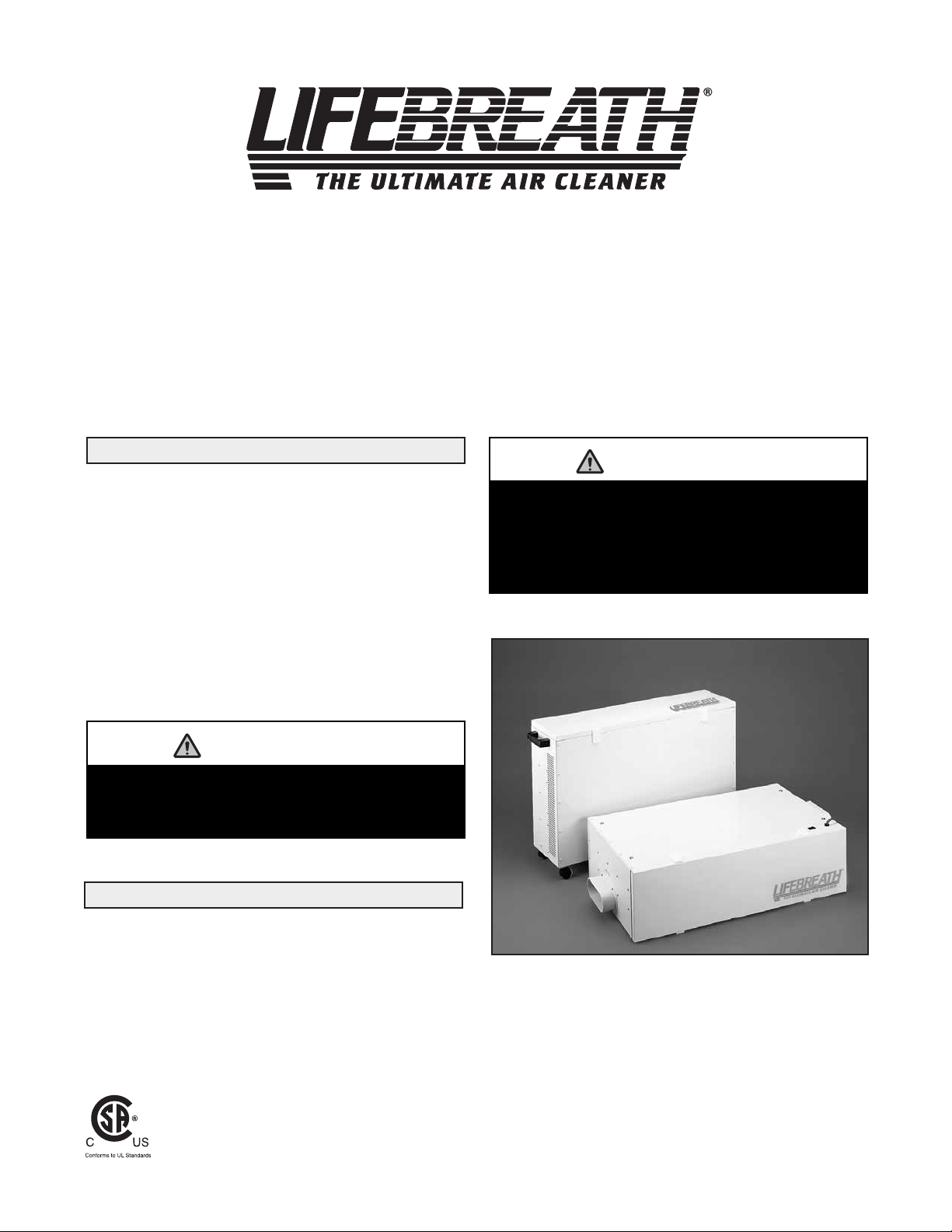
INSTALLATION MANUAL FOR TFP AIR CLEANER
TFP2000 (Wholehouse Model)
TFPC2000 (Portable Console Model)
WHOLEHOUSE AND PORTABLE
CONSOLE MODELS
ATTENTION
ATTENTION
The TFP can be installed in several different ways.
Please read all suggested methods before
attempting installation.
The furnace fan and/or HRV must operate
continuously for Type 1 and Type 2 installations.
If they do not operate continuously, then
interlocking them electrically with the TFP is
acceptable. Consult a certified electrician.
Page 2
2
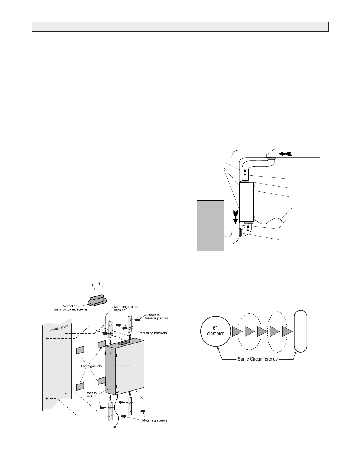
TFP Directly Connected to
Forced Air Heating System
1. Install 6” oval port collar (provided) on top and
bottom of TFP (Fig. 1). Use (4) 8/32” X 3/8”
screws (provided).
2. Remove protective backing from pieces of
foam and stick them to the 4 corners of the TFP
on the side being mounted against the plenum.
3. Remove the 4 mounting bolts from the back of the
TFP cabinet. (Fig. 1)
4. Attach top and bottom mounting brackets
(provided) vertical to the TFP cabinet and
reinstall mounting bolts.
5. Lift the TFP into position. Edge of TFP must be
positioned on plenum to allow clearance
needed for latches.
6. Install the (4) 8/32” X 3/4” mounting screws
(provided) through the brackets and into position.
Tighten and secure.
7. TFP should now sit securely against the plenum
with the foam in between.
8. Cut 2 - 6” holes in the plenum. Install ducting to
join TFP to the return air plenum (Fig. 2).
NOTE: Do not support the weight of the TFP on
the duct. Duct must be open and not pinched.
NOTE: Due to possible noise transfer through
the duct system, it may be preferable in some
situations to hang the TFP a short distance from
the plenum, and connect by running flexible
ducting between them. Four nylon hanging straps
are provided for this option.
Type 1 Installation
* Direct connect to furnace/air handler return, or hang
separately and connect to plenum with flexible ducting.
TYPE 1 INSTALLATION
Figure 1
T
F
P
Cold Air Return
Air flow direction
6" port collars
Access door
Power supply
Mounting bracket
Ducting (not included)
Clean (filtered) air port
Mounting bracket
Foam gaskets
FURNACE
Air Flow
Supply Plenum
Install plate here
1" Height
Figure 2
Round port bent to oval
Simply bend a standard duct fitting to the correct shape,
and attach to the oval port using the same method as
for a round port.
TFP
TFP
TFP
TFP air cleaner
Page 3

3
TFP Connected to Heat Recovery Ventilator
LOCATION
The TFP should be located in the main trunk of
the fresh air to house line, after the Heat
Recovery
Ventilator (HRV) and before any branch
lines. (Fig. 3)
MOUNTING
1. Locate mounting bolts (4) on side of TFP cabinet
for vertical hanging (Fig. 3) and remove.
2. Measure distance between the bolts and mark it
on the floor/header joist where the TFP is to be hung.
3. Fasten hanging straps to floor joists using wide
head nails or screws with washers.
4. Insert hanging bolts through prepunched holes in
straps and lift TFP into position. Tighten and secure bolts.
DUCTING
1. Install (2) 6” oval port collars (provided) on TFP
cabinet with (8) 8/32” X 3/8” sheet metal screws
provided (Fig. 3).
2. The ducting between the TFP and the HRV,
and between the TFP and the main supply
trunk line to the house, should be kept as
straight as possible.
3. A relief opening or breathing T is required to
prevent pressure differences.
4. A short piece (1-2 foot) of flexible ducting should
be used on both sides of the TFP (Fig. 3).
This will reduce vibration and noise transfer
if present.
NOTE: Please refer to the HRV installation manual
for proper ducting of that appliance.
Type 2 Installation
* “Breathing T” is designed to assist in neutralizing
pressure differences which can occur between HRV
and TFP when joined together.
TYPE 2 INSTALLATION
Figure 3
FLOOR JOISTS
Hanging straps (4)
6" port collars
TFP
Access door
Main supply trunk
Flexible ducting
TFP air cleaner
Power cord
Air flow
H
C
N
A
R
B
o
T
IN
L
HRV
Relief opening
(breathing T)
or leave a 4" - 6"
gap between the
TFP and the HRV
Flexible ducting
(fresh air supply)
Mounting bolts
CAUTION
The room in which the “breathing T” is open
should be free of combustion equipment such as
gas hot water tanks and furnaces. If the “T”
must be exposed in these areas, a pressure test
(spillage or backdraft test) should be conducted
on the combustion equipment after everything is
installed.
S
E
Page 4

TFP Independent Installation
No HRV, Radiant Heating System
LOCATION
1. A TFP is usually installed in a basement area
where air flow noise will be negligible to the occupants.
2. A central location between the clean air supply
grille and return grille is recommended.
MOUNTING
Refer to “Mounting” under Type 2 Installations.
DUCTING
1. Install (2) 6” oval port collars (provided) on TFP
cabinet with (8)8/32” X 3/8” sheet metal screws
provided (Fig.4).
2. Ducting will usually consist of one return with grille
from one side of the home, and one supply
with
grille at the opposite end of the home (Fig. 4).
3. Ductwork should be no smaller than the size of the
port collars (6”) on the TFP.
4. Ductwork should be kept as short and straight as
possible to allow for good air circulation.
NOTE: For installations of more than one return or
supply (greater than .5 e.s.p.) , it is often necessary to
add an inline fan to the system as a booster.
OPERATING INSTRUCTIONS
A lighted ON/OFF switch indicates that the unit is
operating. It is recommended the unit run continuously
to provide the full benefits of particulate removal from
your home.
ANNUAL CHECK-UP
As each home has differences of size, occupancy,
loca-
tion, infiltration rates and homeowner needs, it is hard
to
estimate when the collectors will need to be changed.
Because of the way air moves through the TFP, the
collectors are divided into 3 separate sections.
Collectors 1 & 2, then 3 & 4 and then 5 & 6. Collectors
1 & 2 will need to be replaced before the others, then
3 & 4 and so on. You may want to change 1 & 2 again
before 3 & 4 or 5 & 6.
The collectors will slide out. Some discolouration of
the collector medium can be expected and when loose
dust falls from the collector, it is time to replace it.
Turn the TFP, furnace fan and HRV off. Open the door
and slide out the collectors to check buildup and do an
annual inspection of overall unit. Before replacing any
collectors, vacuum any dust inside the cabinet or surrounding area. When replacing the collectors, make
sure the pleats are horizontal when sliding collectors back into the TFP. Close the door and restart
TFP, furnace and HRV fan.
When your TFP is installed with a forced air heating
system you are still required to use the recommended
furnace filter. This may be a good time to inspect this
filter as well.
When new collectors are required, call your Lifebreath
dealer.
TYPE 3 INSTALLATION
OPERATING INSTRUCTIONS AND ANNUAL CHECK-UP
Type 3 Installation
Figure 4
Return Grille
High wall
or floor grille
optional
1st or 2nd
STORY
FLOOR JOIST (Header)
Access door
6" port collars
BASEMENT
Clean air supply
Hanging
straps (2)
TFP
Ducting
not included
High wall
or floor
grille
optional
 Loading...