

Page 1
Models TFP3000, TFPC3000, TFP3000HEPA, TFPC3000HEPA
Exhaust
Air
Supply
Air
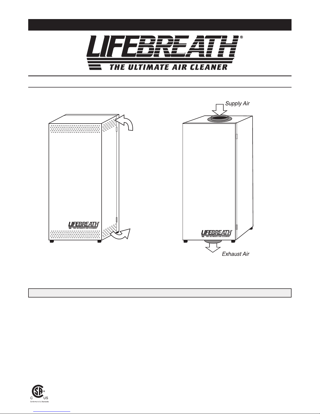
Operation and Installation Manual
Console Portable Models
TFPC3000 and TFPC3000HEPA
Table of Contents
Overview . . . . . . . . . . . . . . . . . . . . . . . . . . . . . . . . . . . . . . . . . . . .2
TFP Questions & Answers . . . . . . . . . . . . . . . . . . . . . . . . . . . . . .3
Installation . . . . . . . . . . . . . . . . . . . . . . . . . . . . . . . . . . . . . . . . . . .3
Materials Supplied . . . . . . . . . . . . . . . . . . . . . . . . . . . . . . . . . . . . .3
Preferred Installation Options . . . . . . . . . . . . . . . . . . . . . . . . . . . .3
Specifications . . . . . . . . . . . . . . . . . . . . . . . . . . . . . . . . . . . . . . .4-5
LEAVE MANUAL FOR HOMEOWNER
NOTE: Due to ongoing research and product development, specifications, ratings and dimensions are subject to change without notice.
Whole House Models
TFP3000 and TFP3000HEPA
Type 1 Installation . . . . . . . . . . . . . . . . . . . . . . . . . . . . . . . . . . .6-7
Type 2 Installation . . . . . . . . . . . . . . . . . . . . . . . . . . . . . . . . . . . . .8
Type 3 Installation . . . . . . . . . . . . . . . . . . . . . . . . . . . . . . . . . .9-10
Operating Instructions and Annual Check-up . . . . . . . . . . . . . . .11
Medical prescription . . . . . . . . . . . . . . . . . . . . . . . . . . . . . . . . . .11
Wiring Diagram . . . . . . . . . . . . . . . . . . . . . . . . . . . . . . . . . . . . . .12
TFP-3000
0108
Page 2
Overview
Exhaust Air
Supply Air
TFP
Collector
TI-127TFP
Part #65-503
TFP
Collector
TI-127TFP
Part #65-503
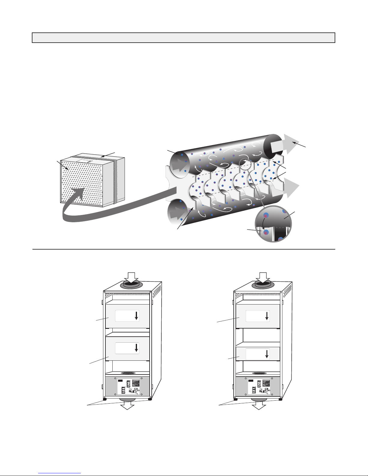
Primary TFP Collector
Replace collector
annually
Secondary TFP Collector
Replace collector
every 2 years
(Due to the performance
characteristics of the
TFP collector, the secondary
collector needs to be
replaced only every
2 years)
HEPA
F
ilt
er
TI-128HEPA
P
art
#
6
5-502
TFP
Collector
T
I-127TFP
P
art #6
5-503
Replace collector
annually
Replace filter
every 3 years
(Due to the performance
characteristics of the
TFP collector, the Hepa
filter only needs to be
replaced every 3 years)
60-TFPC-3000
CAUTION/ATTENTION
BLUE
BLACK
BLACK
BLACK
G
Neutral WHITE
Line BLACK
Ground GREEN
HIGHSPEED
OFF
LOW SPEED
DEFOND
SWITCH
120VAC
60Hz
FANMOTOR
1
2
3
TRANSFORMER
TERMINALBLOCK
BLACK
WHITE
RED
BLUE
WHITE
RED
BLACK
BLACK
BLUE
RED
WHITE
WHITE
WHITE
BROWN
G
GREEN/YELLOW
370V50/60HZ
CAPACITOR
10
UF
TFPCONSOLE MODEL
WIRINGDIAGRAM
Exhaust
Air
Supply
Air
ModelTFPC3000
TFP
Collector
T
TFP
Collector
T
Wash prefilter (foam)
every6months
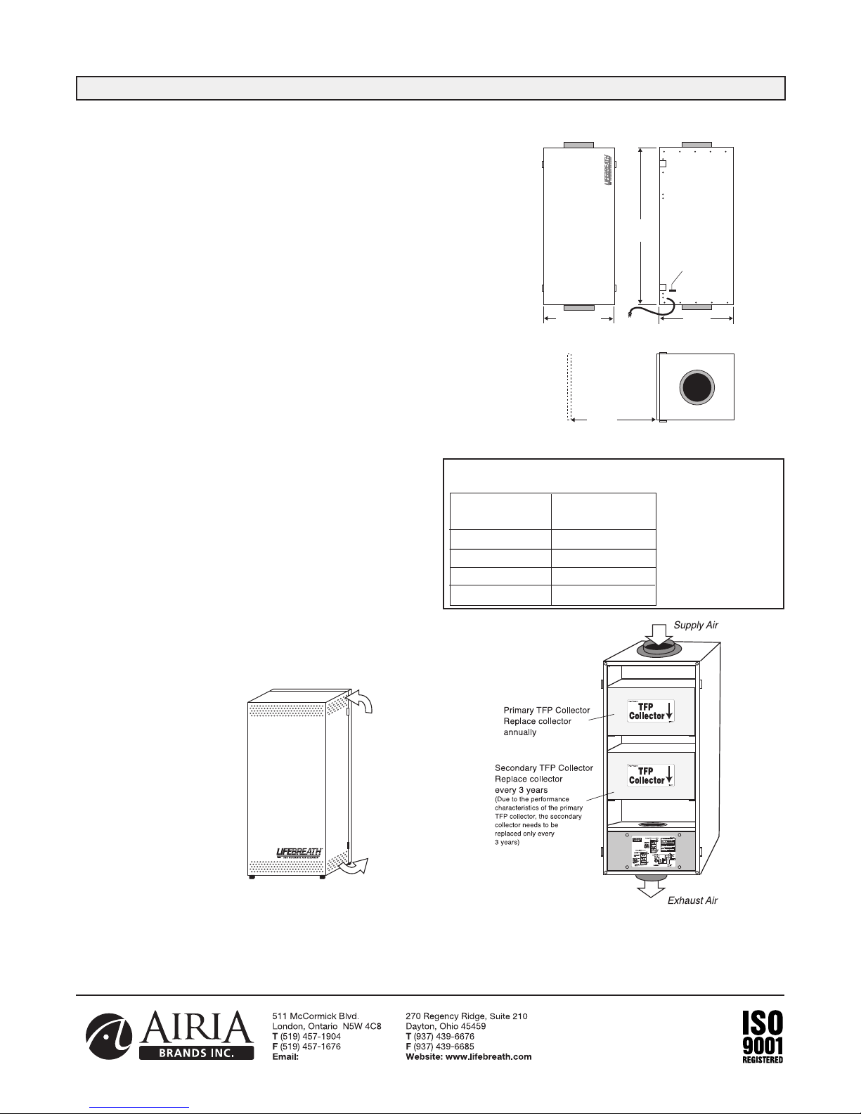
Primary TFP Collector
Replace collector
annually
SecondaryTFPCollector
Replace collector
every2years
(Duetotheperformance
characteristics of the
TFPcollectorthesecondary
collector needs to be
replaced only every
2years)
Rubber mounting
pads forTFPC
tostand on
Exhaust
Air
Supply
Air
ModelTFPC3000HEPA
HEPA
F
ilt
er
TFP
Collector
T
Replace collector
annually
Replace collector
every3years
(Duetotheperformance
characteristics of the
TFPcollectortheHepa
filter only needs to be
replaced every 3 years)
CONSOLE
MODEL
6
0-TFPC-3000
CAUTION /ATTENTION
B
LUE
B
LACK
B
LACK
B
LACK
G
N
eutral
W
HITE
L
ine
B
LACK
G
round
G
REEN
H
IGH SPEED
OFF
LOW SPEED
DEFOND
SWITCH
120 VAC
6
0Hz
FAN MOTOR
1
2
3
T
RANSFORMER
T
ERMINAL BLOCK
B
LACK
W
HITE
R
ED
B
LUE
W
HITE
RED
BLACK
B
LACK
B
LUE
R
ED
W
HITE
WHITE
W
HITE
B
ROWN
G
G
REEN/YELLOW
3
70V~50/60H
Z
C
APACITOR
1
0
UF
T
FPCONSOLE MODEL
W
IRING DIAGRAM
E
xhaust
A
ir
S
upply
A
ir
M
odel TFPC3000
T
FP
Collector
T
T
FP
Collector
T
W
ash prefilter (foam)
every 6 months
Primary TFP Collector
R
eplace collector
a
nnually
S
econdary TFP Collector
R
eplace collector
every2years
(
Due to the performance
c
haracteristics of the
TFP collectorthe secondary
c
ollector needs to be
r
eplaced only every
2
years)
Rubber mounting
p
ads for TFPC
t
ostand on
Exhaust
A
ir
S
upply
A
ir
M
odel TFPC3000HEPA
HEPA
F
ilte
r
TFP
C
ollector
T
R
eplace collector
annually
R
eplace collector
e
very3years
(Due to the performance
characteristics of the
TFP collectorthe Hepa
f
ilter onlyneeds to be
r
eplaced every 3 years)
C
ONSOLE
MODEL
Exhaust Air
Supply Air
Rubber mounting
pads for TFPC to
stand on
Rubber mounting
pads for TFPC to
stand on
Particles are forced out into
areas of no turbulence... and stay
there because there is no airflow
Fabric particle collector
and aluminum spacer panels
Particles in
airstream
Velocity fluctuations
force particles to areas
of no flow
No airflow between
these lines
Clean air
The Turbulent Flow Precipitation Principle
Turbulent
airflow
Turbulent
airflow
T
F
P
C
o
l
l
e
c
t
o
r
P
ar
t
#
6
5
5
0
3
Fabric particle
collector and
aluminum
spacer panels
Foam gasket
Magnified detail of collector panel
TFP3000 Flow Thru Collector
The Li fe br ea th TFP A ir C le an er uses "Turbulent Flow
Precipitation" to remove th e millions of dangerous air borne
particles in your home. This technology is based on the Dullien
Principle which removes tiny airborne particles which enter the
lungs and can cause respiratory problems.
The quiet operating unit has a 2-speed selector switch, along with
a high efficiency fan motor, and a foil faced insulated cabinet that
is easy to clean.
TFP
2
TFP HEPA
Page 3

InstallationOverview
TFP (Turbulent Flow Precipitator) Technology removes health
threatening particles from the air far more effectively than most
other residential cleaners. It operates continuously at maximum
efficiency without the need for constant adjustment and cleanout.
Unlike some air cleaners, it introduces absolutely no ozone into
your home. It cleans the air throughout your home, benefiting all
the family, all the time. The TFP allows air to circulate freely,
without putting any extra load on your air distribution system.
TFP Questions & Answers
Why do I need a TFP Air Cleaner?
The air in today's homes is 3 to 5 times more polluted than outdoor
air creating health problems such as asthma, allergies, headaches,
and fatigue for the home's occupants. The Lifebreath TFP Air
Cleaner will remove 99% of these polluting particles from your
home creating a clean and comfortable environment for you and
your family.
Will I notice a difference in the amount of dust in
my home?
We have received numerous testimonials from satisfied customers
attesting to the significant drop in dust found in the homes where a
TFP is installed.
Does the TFP generate harmful ozone?
The TFP series is an induced airflow system which requires no
electric charge.
Is the TFP a patented unique technology or just
another filter?
Airia Energy Systems hold the patent for this TFP technology.
The TFP series are the only one of its kind.
How much maintenance is involved? How often do
the filters need to be replaced?
As tested under average household dust loading, the TFP should
be inspected annually. Typically the primary collector should be
replaced annually and the secondary collector should be replaced
every 2 years.
Location
The TFP should be installed in a conditioned space with easy
access for maintenance and an annual check up. A TFP is usually
installed in a basement area where air flow noise will be negligible
to the occupants.
Materials Supplied
1 TFP
4 Mounting Brackets
4 Hanging Straps
2 Collar Connections
4 Port Collar Screws
8 Mounting Bracket Screws
4 Pieces of Mounting Foam
1 Set of Installation/Operating Instructions
1 Wiring Diagram
1 Warranty Card
Preferred Installation Options
There are three basic installation options. Select the best method
for your needs.
1. TFP to a Forced Air System; use Return/Return Method
(horizontal or vertical TFP installation)
2. TFP to a Fully Dedicated HRV System
- recommended when you wish to clean the incoming air from
the HRV
3. Stand Alone System – recommended for homes without forced
air systems (ie. radiantly heated homes).
Options
Optional Installation Kit: Part# 99-7TFP
Includes:
– two 7” Duct Connection Collars
– 12.5’ of 7” Duct
– four Nylon Duct Zip Ties
3
Page 4
info@lifebreath.com
Note:
Minimum 16"
(406 mm) required
for ser vice
All duct connections are 7" (178 mm)
OFF/LOW/HIGH
SWITCH
3
4.25"
870 mm
1
4.5"
368 mm
1
4.75"
375 mm
16"
406 mm
F
RONT
S
IDE
END
Exhaust
Air
Supply
Air
C
Specifications TFP3000 and TFPC3000
Motors and Blowers
2 speed, high efficiency PSC Motor - 150 cfm/75 cfm.
110 watts - 120 VAC - standard three prong plug to receptacle.
The TFP is equipped with a standard power supply on 5’5”
(1.6 meters) cable.
OFF/LOW/HIGH Speed Selector Switch
Select 75 cfm (Low) or 150 cfm (High).
Airflow
150cfm @ .4" WC (High Speed)
75 cfm @ .4" WC (Low Speed)
Collectors
Model TFP3000 - Two replaceable TFP collectors
Model TFPC3000 CONSOLE - Two replaceable TFP collectors
• Easy to remove for cleaning and replacement
• Annual inspection recommended
Case
Twenty gauge prepainted galvanized steel (G60) for superior
corrosion resistance
Weight
55 lbs. (24.4 Kgs)
Electrical Codes
Conforms to CSA and UL standards
Mounting the Wholehouse TFP - very flexible
a. Mount to the furnace return
b. Mount between the HRV and the furnace
c. Hang from a joist and duct to the furnace
d. Stand alone installation
Warranty
Units carry a five year warranty on all replacement
parts except the collectors/filters.
Options
65-503R - One replacement TFP Collector
65-502R - One replacement HEPA filter
Optional Installation Kit: Part # 99-TFP
Includes - two 7” Duct Connection Collars
- 12.5’ of 7” Non-insulated Flex Duct
- four Nylon Duct Zip Ties
TFP3000
Model TFP 3000 & TFPC3000 Particle Capture Rate
• A human hair is 100
Particle Size Percentage
(microns) Caught
5 or more 99%
2 - 3 97%
1 95%
0.5 - 0.9 90%
microns wide.
• Spores and pollen
are all larger than 8
microns.
• A micron is 1/1000 of
a millimetre, or less
than 1/2 of 1/10,000
of an inch.
Console Portable
Model TFPC3000
Date: ___________________________________________
Tag: _____________________Qty:___________________
Project: _________________________________________
Engineer: _______________________________________
Contractor: ______________________________________
Supplier: ________________________________________
Quote#: _________________________________________
Submitted by: ____________________________________
4
Page 5

info@lifebreath.com
N
ote:
Minimum 16"
(
406 mm) required
for service
All duct connections are 7" (178 mm)
OFF/LOW/HIGH
SWITCH
34.25"
8
70 mm
14.5"
3
68 mm
14.75"
3
75 mm
1
6"
406 mm
FRONT
SIDE
E
ND
Specifications TFP3000HEPA and TFPC3000HEPA
Exhaust
Air
Supply
Air
Motors and Blowers
2 speed, high efficiency PSC Motor - 150 cfm/75 cfm.
110 watts - 120 VAC - standard three prong plug to receptacle.
The TFP is equipped with a standard power supply on 5’5”
(1.6 meters) cable.
OFF/LOW/HIGH Speed Selector Switch
Select 75 cfm (Low) or 150 cfm (High).
Airflow
150cfm @ .4" WC (High Speed)
75 cfm @ .4" WC (Low Speed)
Collectors
Model TFP3000 - One replaceable TFP collector and one
replaceable HEPA filter
Model TFPC3000HEPA CONSOLE - One replaceable TFP
collector and one replaceable HEPA filter
• Easy to remove for cleaning and replacement
• Annual inspection recommended
Case
Twenty gauge prepainted galvanized steel (G60) for superior
corrosion resistance
Weight
55 lbs. (24.4 Kgs)
Electrical Codes
Conforms to CSA and UL standards
Mounting the Wholehouse TFP - very flexible
a. Mount to the furnace return
b. Mount between the HRV and the furnace
c. Hang from a joist and duct to the furnace
d. Stand alone installation
Warranty
Units carry a five year warranty on all replacement
parts except the collectors/filters.
Options
65-503R - One replacement TFP Collector
65-502R - One replacement HEPA filter
Optional Installation Kit: Part # 99-TFP
Includes - two 7” Duct Connection Collars
- 12.5’ of 7” Non-insulated Flex Duct
- four Nylon Duct Zip Ties
TFP3000HEPA
Model TFP3000HEPA & TFPC3000HEPA Particle Capture Rate
Particle Size (microns) Percentage Caught
.3 or more 99.7%
• Model TFP3000HEPA - 99.97% efficient at .3 microns.
• A human hair is 100 microns wide.
• Spores and pollen are all larger than 8 microns.
• A micron is 1/1000 of a millimetre, or less than 1/2 of 1/10,000 of an
inch.
Console Portable
Model
TFPC3000HEPA
Date: ___________________________________________
Tag: _____________________Qty:___________________
Project: _________________________________________
Engineer: _______________________________________
Contractor: ______________________________________
Supplier: ________________________________________
Quote#: _________________________________________
Submitted by: ____________________________________
5
Page 6

Metal Hanging
Straps (Supplied)
& Mounting Bolts
7" Collar
Foam
Air
Cleaner
Return Air
Forced Air
Furnace
Return Air
Supply Air
TYPE 1 INSTALLATION - Option A Standard Design
The furnace fan and/or HRV must operate
continuously for Type 1 and Type 2 installations.
If they do not operate continuously, then
interlocking them electrically with the TFP is
acceptable. Consult a certified electrician.
ATTENTION
Figure 2
TFP Directly Connected to Forced Air Heating
System
1. Install 7” collar (provided) on top and bottom of TFP (Fig. 1).
Use (4) 8/32” X 3/8” screws (provided).
2. Remove protective backing from pieces of foam and stick
them to the 4 corners of the TFP on the side being mounted
against the plenum.
3. Remov e t he 4 m oun ting bolts from the back of the TFP
cabinet. (Fig. 1)
4. Attach top and bottom mounting brackets (provided) vertical to
the TFP cabinet and reinstall mounting bolts.
5. Lift the TFP into position. Edge of TFP must be positioned on
plenum to allow clearance needed for latches.
6. In stall the (4) 8/32” X 3/4” mounting sc rews (provided)
through the brackets and into position. Tighten and secure.
7. TFP should now sit securely against the plenum with the foam
in between.
8. Cut 2 - 7" holes in the return air plenum. Install ducting to join
TFP to the return air plenum (Fig. 2).
Figure 1
NOTE: Do not support the weight of the TFP on the duct.
Duct must be open and not pinched.
NOTE: Due to possible noise transfer through the duct system,
it may be preferable in some situations to hang the TFP a short
distance from the plenum, and connect by running flexible
duct in g between t he m. Four n yl on hanging st ra ps ar e
provided for this option.
6
Page 7

TYPE 1 INSTALLATION - Option B Horizontal Design
minimum 40 inches
ForcedAir
Furnace
Return Ai r
Supply Air
Air
Cleaner
The furnace fan and/or HRV must operate
continuously for Type 1 and Type 2 installations.
If they do not operate continuously, then
interlocking them electrically with the TFP is
acceptable. Consult a certified electrician.
ATTENTION
ForcedAir
Furnace
Return Ai r
Supply Air
Air
Cleaner
The furnace fan and/or HRV must operate
continuously for Type 1 and Type 2 installations.
If they do not operate continuously, then
interlocking them electrically with the TFP is
acceptable. Consult a certified electrician.
ATTENTION
Use Option B when Option A is not practical.
TYPE 1 INSTALLATION - Option C Vertical Design
Use Option C when Option A
is not practical.
7
Page 8

The room in which the “breathing T” is open
should be free of combustion equipment such as
gas hot water tanks and furnaces. If the “T”
must be exposed in these areas, a pressure test
(spillage or backdraft test) should be conducted
on the combustion equipment after everything is
installed.
CAUTION
TYPE 2 INSTALLATION To a Fully Dedicated HRV System
Breather Tube
(Standard
Galvanized
"Tee" Fitting)
Fresh Air
to House
Fresh Air
to House
Stale Air
from house
Air
Cleaner
HRV/ERV
Breather
Te e
Outdoors
Figure 3
TFP Connected to Heat Recovery Ventilator
Location
The TFP should be located in the main trunk of th e fre sh ai r to
house line, after the Heat Recovery Ventilator (HRV) and before
any branch lines. (Fig. 3)
Mounting
1. Locate mounting bolts (4) on side of TFP cabinet for vertical
hanging (Fig. 3) and remove.
2. Meas ure dist ance betwe en th e bolts and m ark i t on the
floor/header joist where the TFP is to be hung.
3. Fasten hanging straps to floor joists using wide head nails or
screws with washers.
4. Insert hanging bolts through prepunched holes in straps and lift
TFP into position. Tighten and secure bolts.
Ducting
1. Install (2) 7” collars (provided) on TFP cabinet with (8)
8/32” X 3/8” sheet metal screws provided.
2. The ducting between the TFP and the HRV, and between the
TFP and the main supply trunk line to the house, should be
kept as straight as possible.
3. A relief opening or breathing T is required to prevent pressure
differences.
4. A short piece (1-2 foot) of flexible ducting should be used on
both sides of the TFP (Fig. 3). This will reduce vibration and
noise transfer if present.
NOTE: Please refer to the HRV installation manual for proper
ducting of that appliance.
Breathing T
The “Breathing T” is designed to assist in neutralizing pressure
differences which can occur between the HRV and the TFP when
joined together. The “Breathing T” should be situated in an area
with suitable indoor air quality (IAQ). Avoid mechanical rooms
and workshops. If required, an external connection should be made
from the “Breathing T” to an area with suitable IAQ (the air
should be free of fumes, vapors, odors, or large airborne particles
etc.).
8
Page 9

TYPE 3 INSTALLATION Independent Duct System (No HRV)
This installation configuration is
recommended for homes without
forced air systems (i.e. radiantly
heated homes). The duct should be
sized and designed to achieve a
sweeping action from one end of the
home to the other. Considerations
may include strategic clean air
placement for allergy or asthma
sufferers.
Suggested Air Cleaner locations:
• Mechanical Room
• Attic (Extra consideration
is required to ensure heat loss
through duct work is minimized)
• Closet
Figure 4
TFP Independent Installation No HRV, Radiant
Heating System
Location
1. A TFP is usually installed in a basement area where air flow
noise will be negligible to the occupants.
2. A central location between the clean air supply grille and
return grille is recommended.
Mounting
Refer to “Mounting” under Type 2 Installations.
Ducting
1. Install ( 2) 7” collars (provided) on TFP cabinet with (8)
8/32” X 3/8” sheet metal screws provided (Fig.4).
2. Ducting will usually consist of one return with grille from one
side of the home, and one supply with grille at the opposite
end of the home (Fig. 4).
3. Ductwork should be no smaller than the size of
the port collars (7”) on the TFP.
4. Ductwork should be kept as short and straight as possible to
allow for good air circulation.
Note: For installations of more than one return or supply
(greater than .5 e.s.p.), it is often necessary to add an in-line
fan to the system as a booster.
9
Page 10

Ép
u
r
a
te
u
r
d
'
a
i
r
Bureau ou salle de classe
Espace climatisé
Air
Cleaner
TYPE 3 INSTALLATION Alternative Applications
Office or Classroom Application
Work Table Application
10
Page 11

Operating Instructions and Annual Check-up
Disconnect all power sources before attempting
any service.
CAUTION
Prescription
for
Health Care Product
PATIENT NAME
ADDRESS
PHYSICIAN NAME
ADDRESS
PHYSICIAN SIGNATURE
Your doctor has prescribed the use of an Air Cleaner
to aid in the relief of your medical condition.
For allowable tax deduction or insurance purposes, please
retain a completed copy of this form for your records.
TFP-03
Operating Instructions
It is recommended the unit run continuously to provide the full
benefits of particulate removal. Use the OFF/LOW/HIGH speed
selection switch to select high (150cfm) or low (75(cfm) speed.
Maintenance
Annual inspection is recommended for cleaning and replacement
of the Collectors/HEPA filter. Discard and replace the collectors
when requi red. Nor mally th e primary col lector i s r eplaced
annually and the secondary collector is replaced every 2 years.
As each home has differences o f s ize, occupancy, location,
infiltration rates and homeowner needs, it is hard to estimate when
the collectors will need to be changed.
The collectors will slide out. Some discolouration of the collector
medium can be expected and when loose dust falls from the
collector, it is time to replace it. Turn off the TFP, furnace fan and
HRV. Open the door and slide out the collectors to check buildup
Medical Prescription
and do an annual inspection of overall unit. Before replacing any
collectors, vacuum any dust inside the cabinet or surrounding area.
When replacing the collectors, make sure the directional arrows
are noted and the collectors are installed correctly. Close the door
and restart TFP, furnace and HRV fan.
When your TFP is installed with a forced air heating system you
are still required to use the recommended furnace filter. This may
be a good time to inspect this filter as well.
When new collectors are required, call your dealer.
Model TFP3000 - Two replaceable TFP collectors
Model TFP3000HEPA - 1 TFP Collector, 1 HEPA filter
The TFP may qualify for an insurance and/or a medical tax
deduction with a physician's prescription.
11
Page 12

Wiring Diagram
BLUE
BLACK
BLACK
BLACK
G
N
eutral
WHITE
Line BLACK
Ground GREEN
H
IGH SPEED
OFF
L
OW SPEED
DEFOND
S
WITCH
1
20 VAC
60 Hz
FAN MOTO R
1
2
3
TRANSFORMER
TERMINAL BLOCK
BLACK
WHITE
BLUE
WHITE
BLUE
BLACK
BLACK
BLUE
RED
WHITE
RED
G
GREEN/YELLOW
3
70V~50/60H
Z
C
APAC ITOR
10
UF
DOOR
SWITCH
RED
RED
BROWN
CAUTION /ATTENTION
info@lifebreath.com
12
 Loading...