

Lifebreath max series Installation Manual
MAX Series
Installation Guide
69-MAX-Install 050615

Table of Contents
Location .................................................................................................................................... 2
Pre-Installation Notes ................................................................................................................ 3
Simplified Installation (Return/Return Method) ............................................................................ 4
Partially Dedicated System ......................................................................................................... 5
Fully Dedicated System .............................................................................................................. 6
Optional duct configuration for models: 195DCS, 195ECM, and 300DCS ............................................. 7
Mounting the 65MAX.................................................................................................................. 8
Hanging Straps .......................................................................................................................... 9
Drain Connection ......................................................................................................................10
Drain Connection 65MAX........................................................................................................... 11
Grilles ......................................................................................................................................12
Grille Fittings ............................................................................................................................ 13
Lifebreath Weatherhood............................................................................................................ 14
Weatherhood Requirements ...................................................................................................... 15
Main Control Installation ........................................................................................................... 16
Mechanical Timers Installation ................................................................................................... 17
Installation and Operation 20/40/60 Minute Timers: 99-DET01 and 99-20M01 ............................. 18
Installer Selectable High Speed Settings..................................................................................... 18
Dimensional Model Diagrams - 95/100/155 Models ..................................................................... 19
Dimensional Model Diagrams - 195/300/205 Models ................................................................... 20
Dimensional Model Diagrams - 65MAX Models............................................................................ 21
Balancing the Airflows ............................................................................................................... 22
Determining the CFM ................................................................................................................ 23
Balancing Collar Instructions ..................................................................................................... 23
Balancing the Airflows with a Pitot Tube .................................................................................... 24
Balancing the Airflows Using the Door Ports ............................................................................... 25
Airflow Reference Chart - 100 Model .......................................................................................... 26
Airflow Reference Chart - 155 Model .......................................................................................... 27
Airflow Reference Chart - 205 Model .......................................................................................... 28
Airflow Reference Chart - 65MAX Model..................................................................................... 29
Troubleshooting ....................................................................................................................... 30
Location - Installation Notes
Install the unit in a heated space that provides clearance for service access. A typical location is in
either a mechanical room or an area close to the outside wall within close proximity to where the
weatherhoods are mounted. If a basement area is inconvenient or non-existent, install the unit in a
utility room or laundry room. Attic installations are not recommended due to:
The complexity of work to install
Freezing conditions in the attic
If attic installation is necessary the unit must be situated in a conditioned space.
Leave sufficient clearance at the front of the access door for servicing the air filters and core. The
recommended clearance is a minimum of 25 in (635 mm) for opening and closing the door. Airia
provides four straps for hanging the unit from the basement floor joists.
Difficulty of access for servicing and cleaning
2
Pre-Installation Notes
Read this notice before installing unit:
Note
Due to ongoing research and product development, specifications, ratings, and dimensions are subject to change
without notice.
Attention
Do not apply electrical power to the unit until after the completion of the installation (including installation of low
voltage control wiring).
Ensure the installation and wiring is in accordance with CEC, NEC, and local electrical codes.
Plug the unit into a standard designated (120 VAC) electrical outlet with ground.
The use of an extension cord with this unit is not recommended. If the installation requires further wiring, have a
licensed electrician make all of the electrical connections. The recommended circuit is a separate 15 A/120 V circuit.
Caution
Before installation, careful consideration must be given to how this system will operate if connected to any other
piece of mechanical equipment, i.e. a forced air furnace or air handler, operating at a higher static. After
installation, the compatibility of the two pieces of equipment must be confirmed, by measuring the airflows of the
HRV, by using the balancing procedure found in this manual. Never install a ventilator in a situation where its
normal operation, lack of operation or partial failure may result in the backdrafting or improper functioning of
vented combustion equipment.
Unit must be installed level to ensure proper condensate drainage. Due to the broad range of installation and
operational conditions, consider the possibility of condensation forming on either the unit or connecting ducting.
Objects below the installation may be exposed to condensate.
Warning
Disconnect the power from the unit before cleaning or servicing
To prevent electrical shock, it is extremely important to confirm the polarity of the power line that is switched by the
safety (disconnect) switch. The hot line (black) is the proper line for switching. Use either a voltmeter or test lamp
to confirm the absence of a voltage between the disconnect switch and ground (on the cabinet) while the door is
open. This procedure must be followed, as dwellings are occasionally wired improperly. Always ensure the proper
grounding of the unit.
Improper installation, adjustment, alteration, service or maintenance can cause property damage, personal injury or
loss of life. Installation and service must be performed by a qualified installer or service agency.
3
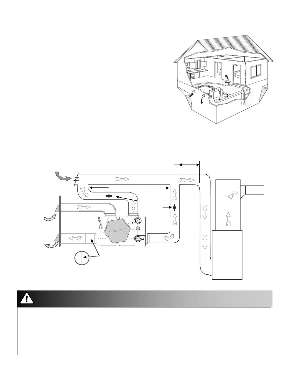
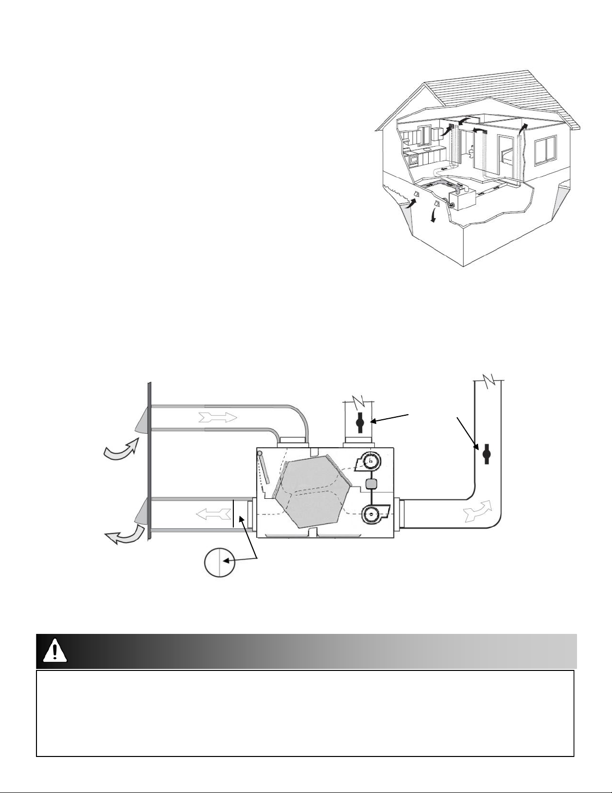
Simplified Installation (Return/Return Method)
Installation Notes
The HRV must be balanced.
Unit should be balanced on high speed with the furnace
blower on.
It is mandatory that the furnace blower run continuously
or HRV operation be interlocked with the furnace blower.
The duct configuration may change depending on the
HRV model.
A backdraft damper is recommended in the exhaust air
duct to prevent outdoor air from entering the unit.
The airflow must be confirmed on site using the
balancing procedures found in this guide.
Spring-Loaded Backdraft Damper (recommended)
Install the Backdraft Damper with the leaf hinge vertical. The damper is installed on the “Stale Air
to Outside Collar”
Return Air
Outdoors
Attention/Warning
40 in (1 m) Minimum
Dampers for
Backdraft Damper
Leaf Hinge
Installed Vertically
(Recommended)
3 ft min.
recommended
balancing
airflows
Cool Air
Return
Forced Air
Furnace
Applications such as greenhouses, atriums, swimming pools, saunas, etc. have unique ventilation requirements
which should be addressed with an isolated ventilation system.
Weatherhood arrangement is for drawing purposes only. 6 ft (2 m) minimum separation is recommended with 18
in (460 mm) above ground.
Check local codes/authority having jurisdiction for acceptance.
Backdraft dampers are recommended for the stale air to outside air duct. This damper prevents outdoor air from
entering the HRV during the operation of the furnace/air handler while the HRV is in standby, off, or recirculating.
4
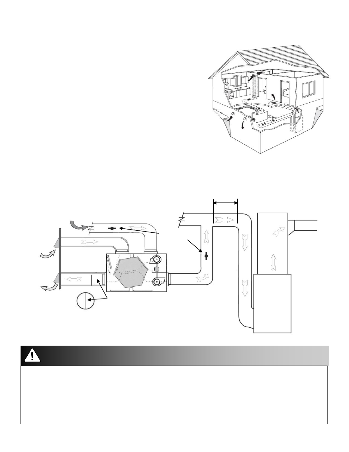
Partially Dedicated System
Installation Notes
The HRV must be balanced.
Unit should be balanced on high speed with the furnace
blower on.
It is recommended that the furnace blower run
continuously or HRV operation be interlocked with the
furnace blower. Refer to building code.
The duct configuration may change depending on the
HRV model.
A backdraft damper is recommended in the exhaust air
duct to prevent outdoor air from entering the unit.
The airflow must be confirmed on site using the
balancing procedures found in this guide.
Spring-Loaded Backdraft Damper (Recommended)
Install the Backdraft Damper with the leaf hinge vertical. The damper is installed on the “Stale Air
to Outside Collar”
EXHAUST AIR from various parts of
home. i.e. bathrooms (if required),
kitchens (if required)
3 ft min.
recommended
RETURN AIR
Dampers for
Outdoors
Backdraft Damper
Leaf Hinge
Installed Vertically
(Recommended)
balancing
airflows
Cool Air
Return
Forced Air
Furnace
Attention/Warning
Applications such as greenhouses, atriums, swimming pools, saunas, etc. have unique ventilation requirements
which should be addressed with an isolated ventilation system.
Weatherhood arrangement is for drawing purposes only. 6 ft (2 m) minimum separation is recommended with 18
in (460 mm) above ground.
Check local codes/authority having jurisdiction for acceptance.
Backdraft dampers are recommended for the stale air to outside air duct. This damper prevents outdoor air from
entering the HRV during the operation of the furnace/air handler while the HRV is in standby, off, or recirculating.
5
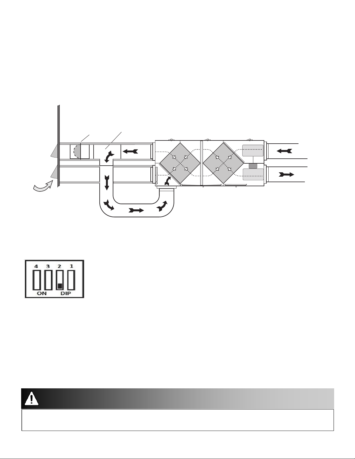
Fully Dedicated System
Installation Notes
The HRV must be balanced.
When balancing, all external exhaust systems should be
turned off (i.e.: range hood, dryer exhaust, bathroom
vents).
All exhausting appliances should have their own make-up
air, as this is not an intended use of the HRV system.
The duct configuration may change depending on the
HRV model.
The airflow must be confirmed on site using the balancing
procedures found in this guide.
Spring-Loaded Backdraft Damper (Recommended)
There is a location for an optional Backdraft Damper with the leaf hinge vertical. The damper is
installed on the “Stale Air to Outside Collar”
Stale air from various parts of
home. i.e. bathrooms (if required)
kitchens (if required)
Fresh air to house:
main living areas,
bedrooms, living
room, rec. room etc.
Dampers for
balancing
airflows
Outdoors
Location for optional
Backdraft Dampers
Leaf Hinge
Installed Vertically
Attention
Applications such as greenhouses, atriums, swimming pools, saunas, etc. have unique ventilation requirements
which should be addressed with an isolated ventilation system.
Weatherhood arrangement is for drawing purposes only. 6 ft (2 m) minimum separation is recommended with 18
in (460 mm) above ground.
Check local codes/authority having jurisdiction for acceptance.
6
Optional duct configuration for models: 195DCS, 195ECM, and 300DCS
Ducting configuration results in recirculating defrost.
Duct Configuration:
Outdoors
Spring Loaded
Backdraft
Damper
From Outside
Standard "Tee"
Fitting
To Outside
NOTE: DIP switch 2 set to "ON" position to activate
recirculation if this configuration is applied.
Stale Air
From House
Recycled Air to
House (defrost
mode only)
HRV in Defrost Mode
Attention
Use this ducting configuration to make a non-recirculating defrost unit operate as a reciculating defrost unit.
7
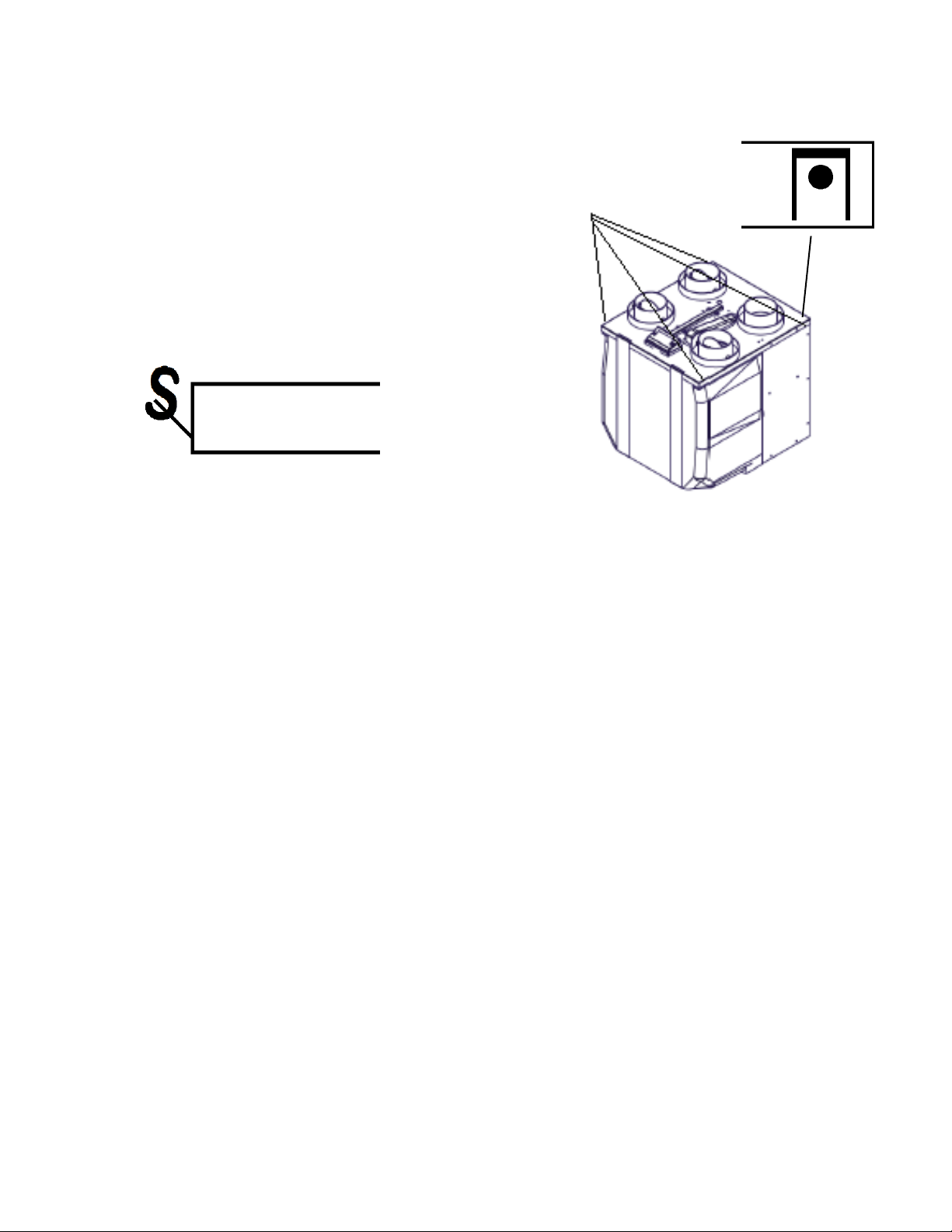
Mounting the 65MAX:
1. Begin by locating the four mounting tabs on
the left and right sides of the unit, at the front
and back.
2. Using a flat / pan head screwdriver, bend
out the four tabs to approximately 45o.
3. Once the tabs have been all bent outwards,
insert the "S" hooks through the four holes on
the tabs.
4. Continue with mounting the HRV usign the
instructions found on page 9.
Four Mounting
Points
8
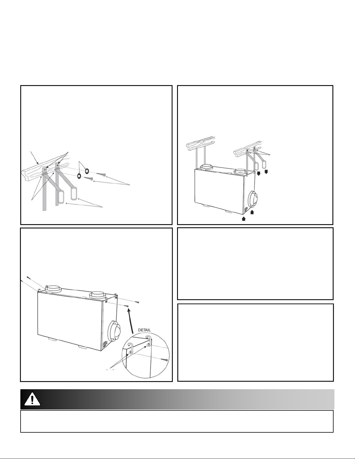
Hanging Straps
Installation Notes
Use 4 screws and 4 washers (not provided) to attach the hanging straps to the floor joists. The
washer must be wider than the eyelet of the grommet on the hanging strap. The hanging straps
are designed to reduce the possibility of noise, resonance and harmonics.
Step 1: Insert the screws and washers
(not included) through the hanging strap
grommets and fasten to the joists.
Figure A
Joist
Buckles
Step 2: Unscrew the 4 machine screws
Hanging Strap Grommets
Washers (not included)
Screws (not included)
Hand Loops
located on the upper side of the unit. Attach
the “S” hooks and reinsert the machine
screws.
Screws
Figure C
Step 3: Hook the bottom grommets of the
straps through the “S” hooks. Pull down
vertically on the handle loops while lifting the
bottom of the unit.
Figure B
Buckles
Hand Loops
Note: Pull down on the
hand loops while lifting
the bottom of the unit.
Step 4: Level the unit from right to left to right
and front to back. Adjust the unit up by pulling
down vertically on the hand loops while lifting up
on the bottom of the cabinet.
Step 5: Fold the hand loops in excess strap
and secure with a nylon tie (not included).
Note: This illustration of
the unit may vary from the
unit you are installing.
“S” Hooks
Attention
Must push up on the bottom of the HRV when pulling the hanging straps.
The unit must be mounted level for proper drainage of the condensate pans.
9
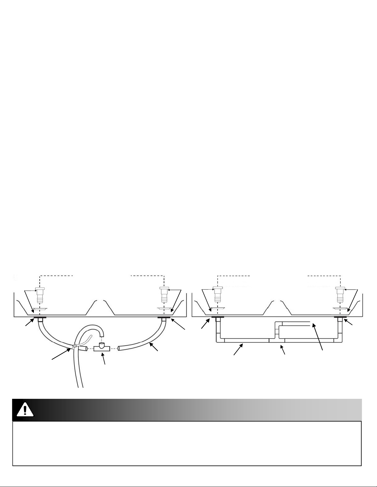
Drain Connection (all units except 65MAX)
Installation Notes
The HRV cabinet has pre-punched holes for the drain (see below).
The HRV may produce some condensation during a defrost cycle. This water should flow into a nearby
drain, or be taken away by a condensate pump.
1.
Apply silicone to the base of the drain spout.
2.
Apply Silicone to base of the beveled washer.
Insert the drain spout through the beveled washer and hole in the drain pan. Be sure to install the
3.
“O-ring” (if supplied) which seals each spout to the pan.
4
.
HAND TIGHTEN the washer and
5.
Construct a P-trap using the plastic tee connector.
Cut two lengths of 1/2 in drain hose (not included) and connect the other ends to the two drain spouts.
6.
7.
Position the tee connector to point upward and connect the drain line.
8.
Tape or fasten base to avoid any kinks.
9.
Pour a cup of water into the drain pan of the HRV after the drain connection is complete. This
lock nut which hold the
drain
creates a water seal which will prevent odours from being drawn up the hose and into the fresh air
supply of the HRV.
spout in place.
The HRV cabinet has pre-punched holes for the drain (see below).
CAUTION: HAND TIGHTEN ONLY
Drain Hose Plumbing
Pre-Punched Holes (2)
Apply
Silicone
Drain
Spout
Drain Pan Drain Pan
Zip Tie
Tee Connector
To Drain
1/2 in I.D.
Drain Hose
Apply Silicone
Drain Spout
1/2 in Hard Pipe
Hard Pipe Plumbing
Pre-Punched Holes (2)
Drain Pan
Drain Pan
Tee
Joint
Apply
Silicone
Drain
Spout
To Drain
Caution
The HRV and all condensate lines must be installed in a space where the temperature is maintained above the
freezing point or freeze protection must be provided.
Drain trap and tubing must be below bottom of door with 1/4 in per foot downwards slope away from unit.
A secondary drain pan may be required to protect from condensate leakage.
10
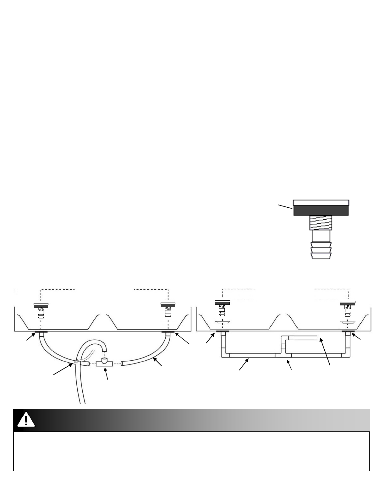
Drain Connection for 65MAX
Installation Notes
The HRV cabinet has pre-punched holes for the drain (see below).
The HRV may produce some condensation during a defrost cycle. This water should flow into a nearby
drain, or be taken away by a condensate pump.
1.
Ensure that the washer has a foam gasket on the bottom of the head. See figure below.
2.
Insert the drain spout through the hole in the drain pan.
HAND TIGHTEN the nylon nut which will hold the drain spout in place.
3.
Construct a P-trap using the plastic tee connector.
4
.
Cut two lengths of 1/2 in drain hose (not included) and connect the other ends to the two drain spouts.
5.
Position the tee connector to point upward and connect the drain line.
6.
Tape or fasten base to avoid any kinks.
7.
Pour a cup of water into the drain pan of the HRV after the drain connection is complete. This
8.
creates a water seal which will prevent odours from being drawn up the hose and into the fresh air
supply of the HRV.
Foam Gasket
The HRV cabinet has pre-punched holes for the drain (see below).
CAUTION: HAND TIGHTEN ONLY
Drain Hose Plumbing
Pre-Punched Holes (2)
Drain Pan Drain Pan
Drain
Spout
Zip Tie
1/2 in I.D.
Drain Hose
Tee Connector
To Drain
Drain Spout
1/2 in Hard Pipe
Hard Pipe Plumbing
Pre-Punched Holes (2)
Drain Pan
Drain Pan
Tee
Joint
Drain
Spout
To Drain
Caution
The HRV and all condensate lines must be installed in a space where the temperature is maintained above the
freezing point or freeze protection must be provided.
Drain trap and tubing must be below bottom of door with 1/4 in per foot downwards slope away from unit.
A secondary drain pan may be required to protect from condensate leakage.
11
Grilles
Adjustable grilles should be used to balance the flow rates into and out of various rooms. The
grilles should not be adjusted after balancing the unit.
Grilles or diffusers should be positioned high on the wall or in the ceiling. Kitchen exhaust should
never be connected to the range hood. They should be installed at least 4 ft (1.2 m) horizontally
away from the stove.
Field supplied balancing dampers should be installed external to the unit to balance the amount
of stale air being exhausted with the amount of fresh air being brought into the house. Refer to
airflow balancing section.
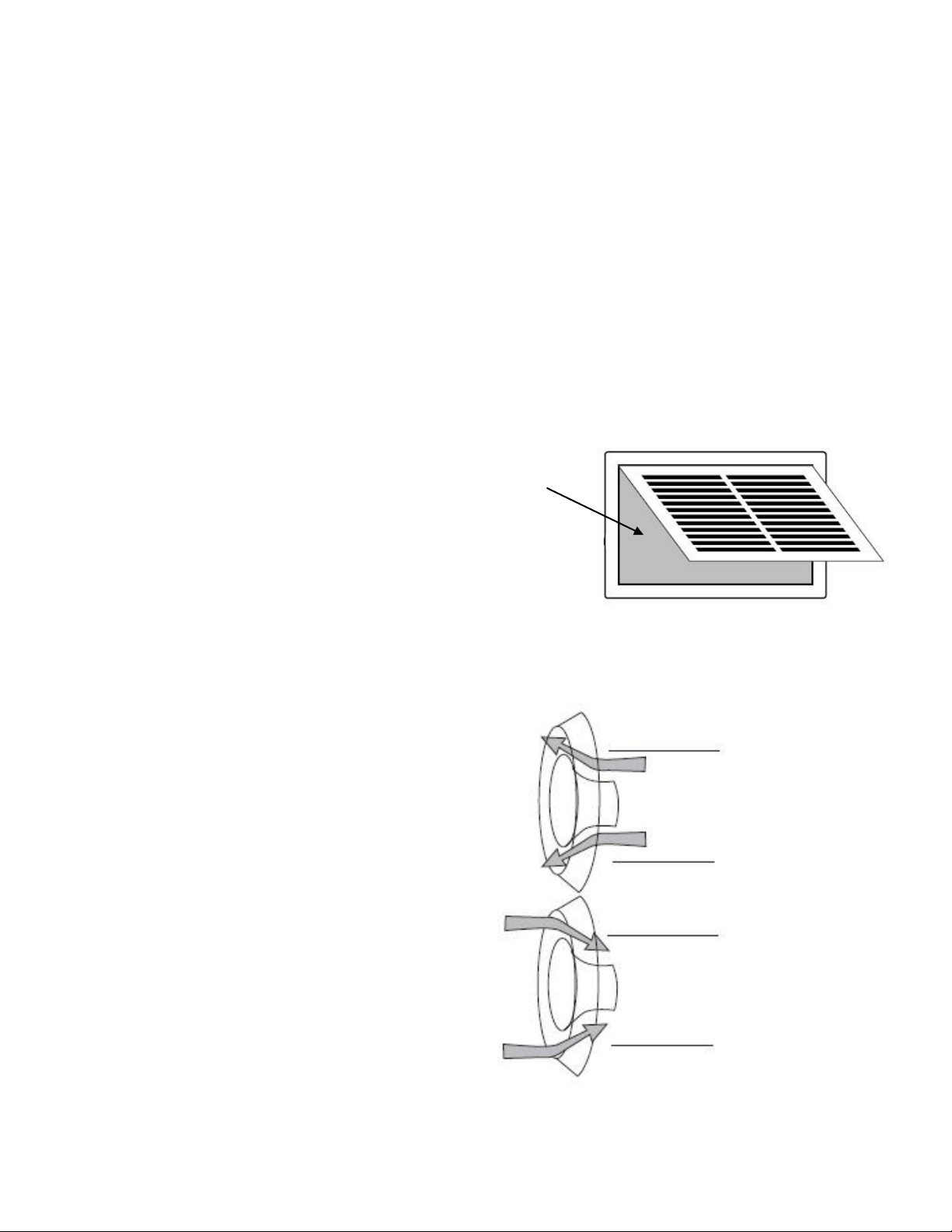
The Lifebreath Kitchen Grille
(part# 99-10-002 6 in x 10 in)
Removable Filter
The Lifebreath Kitchen Grille includes a
removable grease filter. Most building codes
require that kitchen grilles are equipped
with washable filters.
The Lifebreath TechGrille
The TechGrille is a round, fully adjustable grille
which provides quiet air distribution.
4 in (100 mm) Part # 99-EAG4
5 in (125 mm) Part # 99-EAG5
6 in (150 mm) Part # 99-EAG6
8 in (200 mm) Part # 99-EAG8
Airflow
Supply
Airflow
Exhaust
12
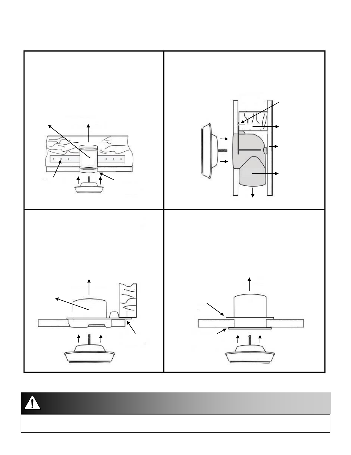
Grille Fittings
Rough-in Metal Fitting
(part # 99-RIMF 4/5/6/8)
Use this rough-in fitting before the drywall is
installed.
Nail or screw the fitting onto the floor post.
Available sizes are 4 in, 5 in, 6 in, and 8 in.
Rough-in
Metal
Fitting
Nail or screw
strap fitting
onto floor
Connect to HRV ducting
Floor joist
Ceiling
Flush mount the
rim with the
finished ceiling TechGrille
Quick Mount Fitting
(part # 99-QM 4/5/6)
Use this rough-in fitting before the drywall is
Installed.
Nail fitting onto the stud.
Available sizes are 4 in, 5 in, and 6 in.
Stack Head Elbow (part # 99-WF4 / 99WF6)
Use this rough-in fitting before the drywall is installed. This
fitting is ideal for running ducting through 2 x 4 (min.)
studded walls.
Nail to stud.
Available sizes are 4 in and 6 in.
Nail stack head
elbow onto stud
2 x 4 Stud
TechGrille
1/2 in drywall
Stack Head
Elbow
Connect to HRV ducting
Ceiling/Wall Fitting (part # 99-CF 4/5/6/8)
Use this fitting for ceiling tiles or finished/installed drywall.
Cut a hole through the ceiling tile, insert the fitting and use the
retaining ring to hold the fitting in place.
For finished/installed drywall, use caulking around the lip if you do
not have access to attach the retaining ring.
Available sizes are 4 in, 5 in, 6 in, and 8 in.
Connect to HRV ducting
Wall/Ceiling
Fitting
Ceiling
TechGrille
Quick Mount
Fitting
1/2 in drywall
Connect to HRV ducting
TechGrille
2 x 4 Stud
Nail or screw quick
mount fitting to stud
Retaining ring
Flush mount the lip of the
ceiling/wall fitting to ceiling
and drywall fitting
Caution
Do not mount exhaust grille within 4 ft (1.2 m) (horizontally) of a stove to prevent grease from entering the unit.
13
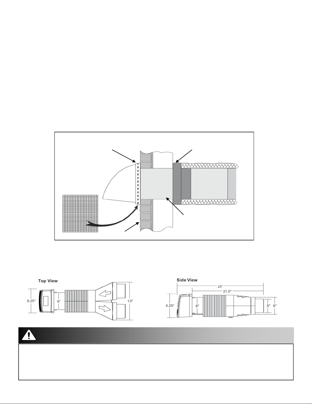
Lifebreath Weatherhood
Fixed covered weatherhoods have a built-in bird screen with a 1/4 in (6 mm) mesh to prevent
foreign objects from entering the ductwork.
Installation Notes
The inner and outer liners of the flexible insulated duct must be clamped to the sleeve of the
weatherhoods (as close to the outside as possible) and the appropriate port on the HRV. It is very
important that the fresh air intake line be given special attention to make sure it is well sealed. A
good bead of high quality caulking (preferably acoustical sealant) will seal the inner flexible duct to
both the HRV port and the weatherhood prior to clamping.
The flexible insulated duct that connects the two outside weatherhoods to the HRV should be
stretched tightly and be as short as possible, to minimize airflow restriction.
Twisting or folding the duct will severely restrict airflow.
Hard (rigid) ducting which has been sealed and insulated should be used for runs over 10 ft
(3.3 m). Refer to your building code.
Collar is supplied to
Screen
(side view)
ensure vapor barrier is 100%
sealed to wall plate
1/4 in (6 mm)
Screen
12 in galvanized
pipe supplied
Exterior wall
Dual Hood Part 99-190
With the Lifebreath Dual Hood, only one 6 in hole is required in the exterior wall to complete two
connections: fresh air intake and stale air exhaust.
Attention/Caution
Contact your local building authority before installation of the Dual Hood to verify compliance with
local building codes.
Caution:
Weatherhood arrangement - requires a minimum of 6 ft (2 m) separation, a minimum of 18 in (460 mm) above the
ground, or above the depth of expected snow accumulation, and a minimum of 3 ft (1 m) from corner of building.
14
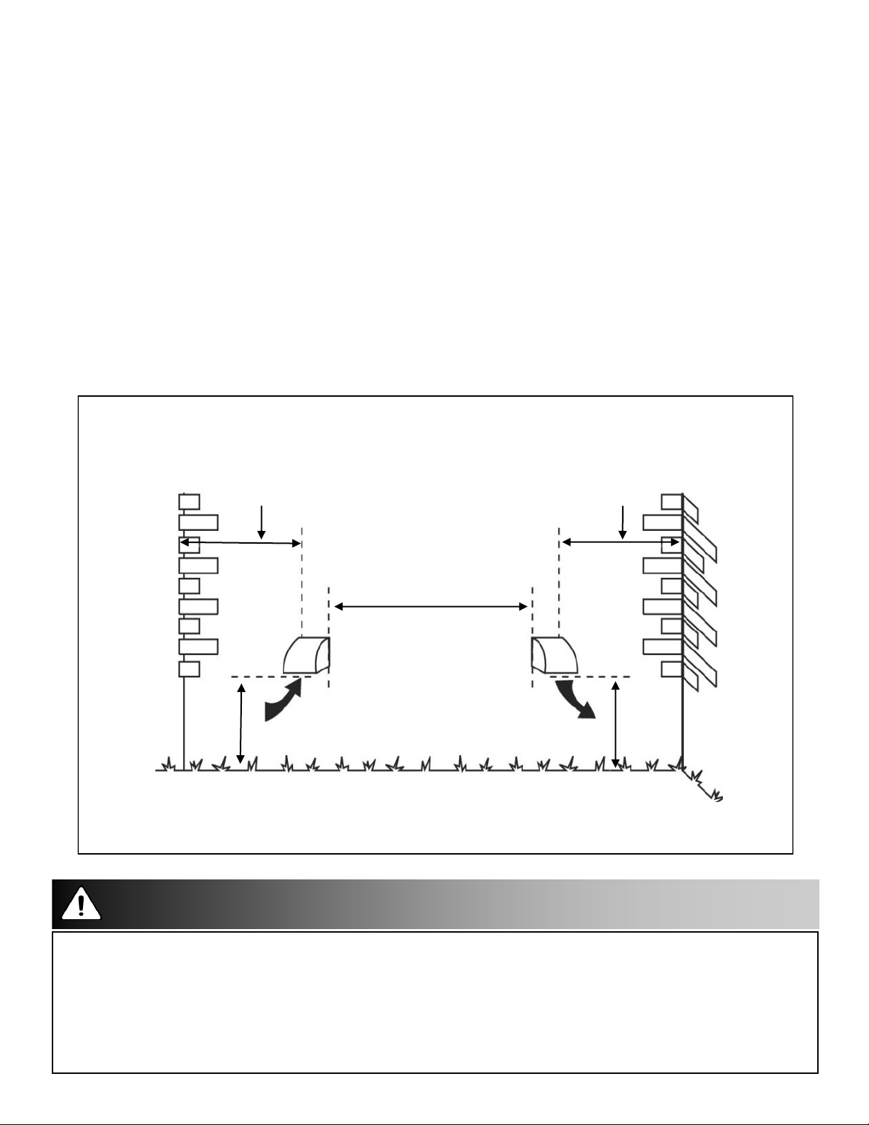
Weatherhood Requirements
At least 6 ft (2 m) should separate the intake and exhaust hood.
At least 18 in (457 mm) above the ground, or above the depth of expected snow accumulation.
At least 3 ft (1 m) from the corner of the building.
Do not locate in garage, attic or crawl space.
Intake:
Should be located upstream (if there are prevailing winds) from the exhaust outlet.
At least 6 ft (2 m) away from dryer vents and furnace exhaust (medium or high efficiency
furnaces).
A minimum of at least 6 ft (2 m) from driveways, oil fill pipes, gas meters, or garbage containers.
Exhaust:
Not near a gas meter, electric meter or a walkway where fog or ice could create a hazard.
OUTSIDE CORNER
3 ft (1 m)
recommended min.
INTAKE
18 in (460 mm)
INSIDE CORNER
3 ft (1 m)
recommended min.
6 ft (2 m)
recommended min.
EXHAUST
18 in (460 mm) min.
Attention/Caution
Contact your local building authority before installation of the Dual Hood to verify compliance with
local building codes.
Caution:
Weatherhood arrangement - requires a minimum of 6 ft (2 m) separation, a minimum of 18 in (460 mm) above the
ground, or above the depth of expected snow accumulation, and a minimum of 3 ft (1 m) from corner of building.
Sealant must be applied as per instructions or leakage and condensation may occur.
Insulate the Fresh Air Supply and Stale Air Exhaust duct work back to the unit.
15
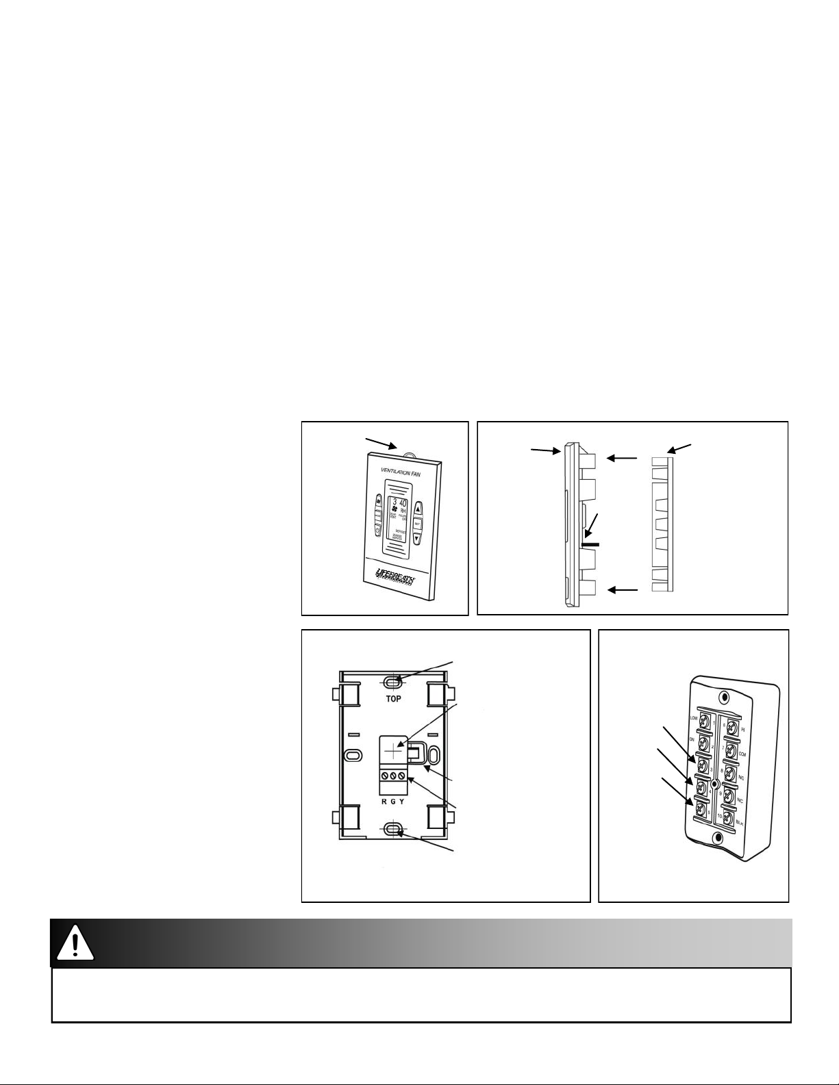
Main Control Installation
The Lifestyle MAX Digital Control 99-DXPL01 or optional Lifestyle MAX Programmable
Control 99-LS01 may be installed onto a flush mounted electrical switch box or it may be surface
mounted onto a wall. Only one master control should be installed to a ventilation system (the face
plate on this illustration may not be exactly the same as yours).
1. Remove the operating instructions card from the top of the control (Figure A).
2. Separate the face plate from the back plate by firmly pulling apart (Figure B). Be careful not to
damage face plate contacts pins.
3. Place the back plate of the control in the desired location on the wall and pencil mark the wall in
the center of the wire opening, top screw hole and bottom screw hole (Figure C).
4. Remove the back plate and drill a 3/8 in opening in the wall to allow for the wire opening and
1/8 in hole for the wall anchors for the top and bottom screw holes (Figure C).
5. Pull 3 wire 20 gauge (min.) 100 ft length (max.), through the opening in the wall and the wire
opening of the back plate (Figure C).
6. Connect red, green, and yellow to the wiring terminals located on the back plate (Figure C).
7. Secure a single wire to the
wire retainer located on the
back plate (Figure C).
8. Attach the back plate to the
wall using the 2 supplied
screws and anchors.
9. Attach the face plate to the
back plate (Figure B).
Note: Be careful to correctly
Operating
Instruction
Card
Figure A
Face
Plate
Face
Plate
Contact
Pins
Figure B
Back
Plate
Dehumidistat
sensor openings
to room air allow
accurate sensor
readings, located
at top and
bottom of control
align the face plate to avoid
damaging the face plate
contact pins.
10. Insert the operating
instructions card into the
control (Figure A).
11. Connect the 3 wire 20 gauge
(min.) 100 ft length (max.) to
Top screw hole
drill a 1/8 in hole
for the top screw
and anchor.
Wire opening
Drill a 3/8 in hole
for the wire
opening.
Wire Retainer
Wiring Terminals
Red #3
Yellow #4
Green #5
the terminal block located on
ventilator (Figure D).
Figure C
Bottom screw hole
drill a 1/8 in hole for
the bottom screw
and anchor.
Figure D
Attention
Pay special attention not to damage the contact pins when removing and detaching the face plate (Figure B).
16
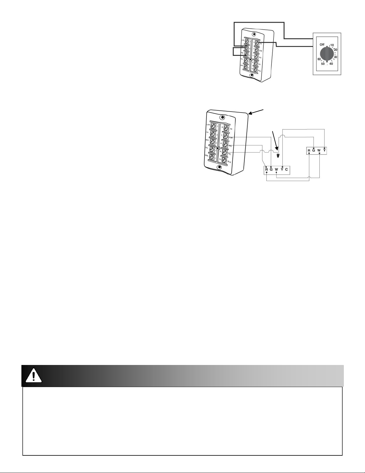
Mechanical Timers Installation 99-101
The Mechanical Timer is a 2 wire “dry
contact” timer. A jumper wire must
be connected between 2 (ON) and
3 (RED). Connect the 2 timer wires
to ON and HI.
2 wire timers require a
jumper wire between
ON and RED on the
terminal
block
Connect the 2
wires from the
timer to ON and HI on the terminal block.
Interlocking the HRV to an Air Handler or Furnace Blower
Connecting the HRV as illustrated will ensure the air
handler/furnace blower motor is operating whenever
the HRV is venting.
HRV Terminal Block
Wire
Connector
The HRV must be interlocked to the furnace/air handler
with a simplified installation (return/return installation)
and should be interlocked with a partially dedicated
installation.
Setting “Standby” When Using a Main Control
Furnace
Terminal Strip
Furnace
Thermostat
The HRV will be “fully-off” when the off position is selected on the main control. Timers and/or other controls will not function when the HRV is in the off position.
The “fully-off” feature can be modified to “standby-off” by adding a jumper on the terminal block
between 2 (ON) and 3 (RED). “Standby” can also be achieved by setting the main control to the ON
position and selecting speed 0*. Timers and/or additional controls will initiate high speed ventilation
when activated.
*Speed 0 is not available on all controls.
Operating the HRV Without a Main Control and Adding Dry Contact Controls
A jumper must be in place between 2 (ON) and 3 (RED) on the terminal block to activate the HRV for
timers and/or dry contact controls.
Adding Dry Contact Controls
Low Speed: A jumper between 2 (ON) and 1 (LOW) initiates low speed ventilation.
High Speed: A jumper between 2 (ON) and 6 (HI) initiates high speed ventilation.
Dehumidistat: A dry contact for a dehumidistat is connected between 2 (ON) and 10 (BLK)
The HRV must have a jumper in place between 2 (ON) and 3 (RED) on the terminal block when
installing the unit without a main control.
Attention/Caution
Timers mount in standard electrical boxes
Use 3 wire 20 gauge (min.) 100 ft length (max.) low voltage wire and multiple timers individually wired back to the unit.
Caution:
Consideration should be given to competing airflows when connecting the HRV in conjunction with an air handler/
furnace blower system.
Building codes in some areas require “fully-off” functionality. Check with your local building authority before
modifying the unit to “standby-off”. Unintentional operation of the HRV by the end user may occur if the unit is
modified from “fully-off” to “standby-off”.
17
Installation and Operation 20/40/60 Minute Timers: 99-DET01 and 99-20M01
Operating your Lifestyle 20/40/60 Minute Fan Timer
Press and release the
speed override cycle. The
speed ventilation for the selected time. The
run time. The
Light
Select Button
Light
to activate a 20, 40 or 60 minute high
will illuminate and the unit will run on high
Light
will dim after 10 sec. for
will flash during the last 5 min. of the cycle.
All timers connected to the unit will illuminate for the duration of the
override when the
Select Button
is pressed.
Lockout Mode
Lockout Mode is useful if you wish to disable the timers.
The timer can be set to lockout mode by pressing and holding the
Button
lect Button.
pressed during lockout mode the
for five seconds. After 5 sec., the
Light
The timer is now in lockout mode. If the
Light
will momentarily illuminate but no
will flash; release the
Select Button
Select
Se-
is
override will be initiated.
If lockout mode is initiated when the timer is activated, the timer will
continue its timed sequence but will not allow any further overrides to be
initiated. Lockout mode can be unlocked by pressing and holding the
Button
Button
for 5 sec. After 5 sec. the
Light
will stop flashing. Release the
and the timer will now operate normally.
Select
Select
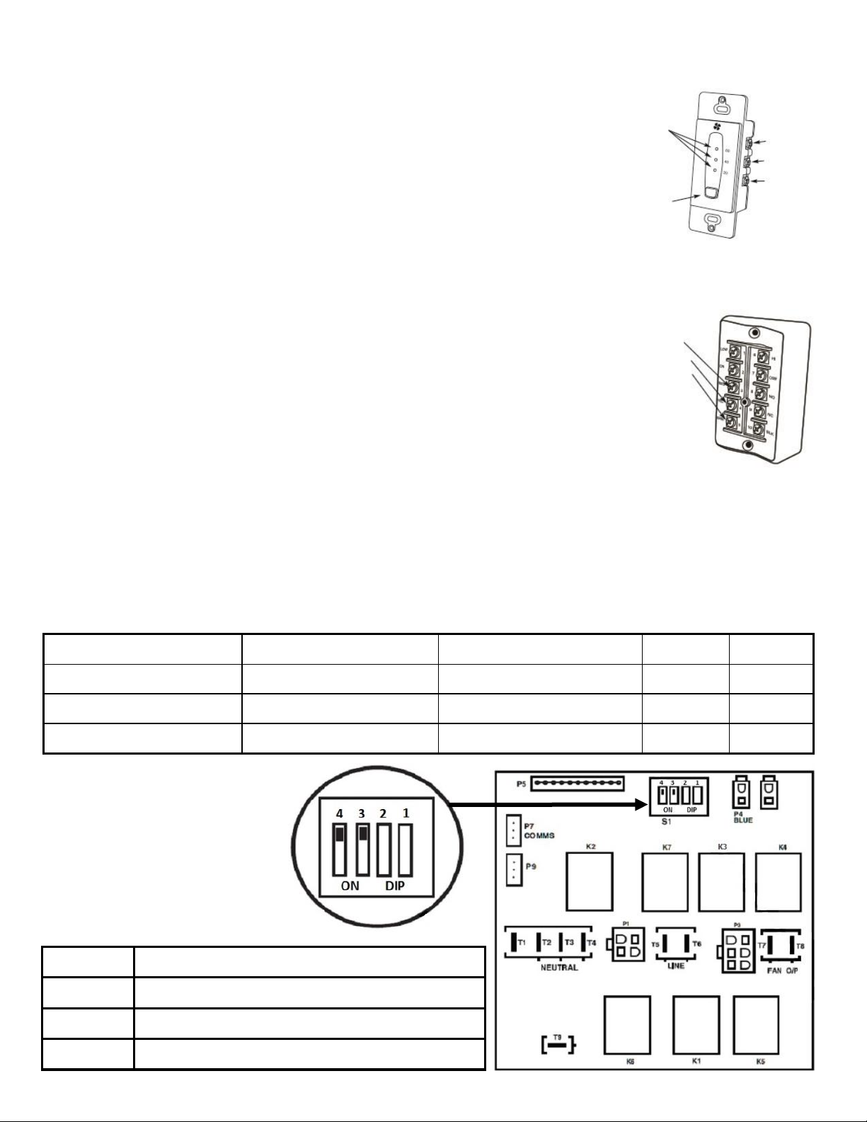
Installer Selectable High Speed Settings
Status
Lights
Select Button
initiates high
speed ventilation
for 20, 40 0r 60 min.
Red #3
Yellow #4
Green #5
Yellow
Red
Green
The circuit board on this unit has adjustable DIP switches for the selection of speeds Hi1, Hi2 or Hi3.
The factory setting is Hi3. Refer to the specification page found online at; www.lifebreath.com for the
airflow rates on Hi1, Hi2 and Hi3.
Note: Low speed is not adjustable.
Description Switch 1 Switch 2 Switch 3 Switch 4
Hi 3 (factory default) Factory Setting “ON” Leave on factory setting ON ON
Hi 2 Factory Setting “ON” Leave on factory setting OFF ON
Hi1 Factory Setting “ON” Leave on factory setting ON OFF
Illustration of DIP switches 3
and 4 in the ON position
(factory setting).
Functionality of DIP
Switches 1 and 2
DIP 1 ON R2000 defrost cycle disabled (factory setting)
DIP 1 OFF R2000 defrost cycle enabled
DIP 2 ON recirculate defrost models
DIP 2 OFF damper defrost and fan defrost models
18
 Loading...