

Lifebreath CAF-U-L4A-36-P16, CAF-U-L2A-48-P16, CAF-D-L4A-36-P16, CAF-H-L4A-36-P16, CAF-D-S4A-24-P16 Operation, Sizing And Installation Manual
...
Operation, Sizing and Installation Manual
Models
CAF-U-S4A-24-P16 (E16)
CAF-D-S4A-24-P16 (E16)
CAF-H-S4A-24-P16 (E16)
CAF-U-L4A-36-P16 (E16)
CAF-D-L4A-36-P16 (E16)
CAF-H-L4A-36-P16 (E16)
CAF-U-L2A-48-P16 (E16)
CAF-U-00-24-P16 (E16)
CAF-U-00-36-P16 (E16)
CAF-U-00-48-P16 (E16)
Hydronic Models with Built-in
Heat Recovery Ventilator (HRV)
MANUFACTURED WITH
AIRCOM ELECTRONICS
69-CAF
0912
Never install an HRV/ERV in a situation
where its normal operation, lack of operation
or partial failure may result in the
backdrafting or improper functioning of
vented combustion equipment!
CAUTION
Assess how the operation of an HRV/ERV
may interact with already installed vented
combustion equipment (ie. Gas Furnaces,
Oil Furnaces, Wood Stoves, etc.).
CAUTION
Table of Contents
The Clean Air Furnace hydronic coil is not to
be used for chilled water applications where
condensation is expected.
ATTENTION
Air Condition coil freezing can damage the
hydronic coil of the Clean Air Furnace.
Install a Freeze Thermostat Kit to your air
conditioning coil to prevent coil freeze up.
Check with your air conditioner distributor to
obtain a Freeze Thermostat Kit.
ATTENTION
Do not apply electrical power to the unit until
installation has been fully completed (including
low voltage control wiring).
Introduction
Overview of the Clean Air Furnace ..................................3
Description and Purpose
Operation Heating/Cooling...............................................4
The Recovery Core ...........................................................5
Combo System Basic Principles .......................................6
Plumbing......................................................................7-14
Installation .................................................................15-17
Pitot Tube Air Flow Balancing ..................................18-19
Function and Controls ...............................................20-21
Optional Dehumidistat
Optional Timers ..............................................................22
Wiring the Controls.........................................................23
Aircom Relays ................................................................24
Start-up Procedure ..........................................................25
Register for your warranty at www.lifebreath.com
Airia will require the Model and Serial Number to register the unit.
TO BE COMPLETED BY CONTRACTOR AFTER INSTALLATION
Service and Maintenance ................................................26
Troubleshooting ..............................................................27
Controlling your HRV
How the Dehumidistat Works.........................................28
Model Number Nomenclature Breakdown.....................29
Specifications ............................................................30-39
System Commissioning ..................................................40
Work Sheets ...............................................................41-42
Wiring Diagrams .......................................................43-44
Installation Date Model
Installing Contractor
Telephone / Contact
Serial Number
2
Introduction
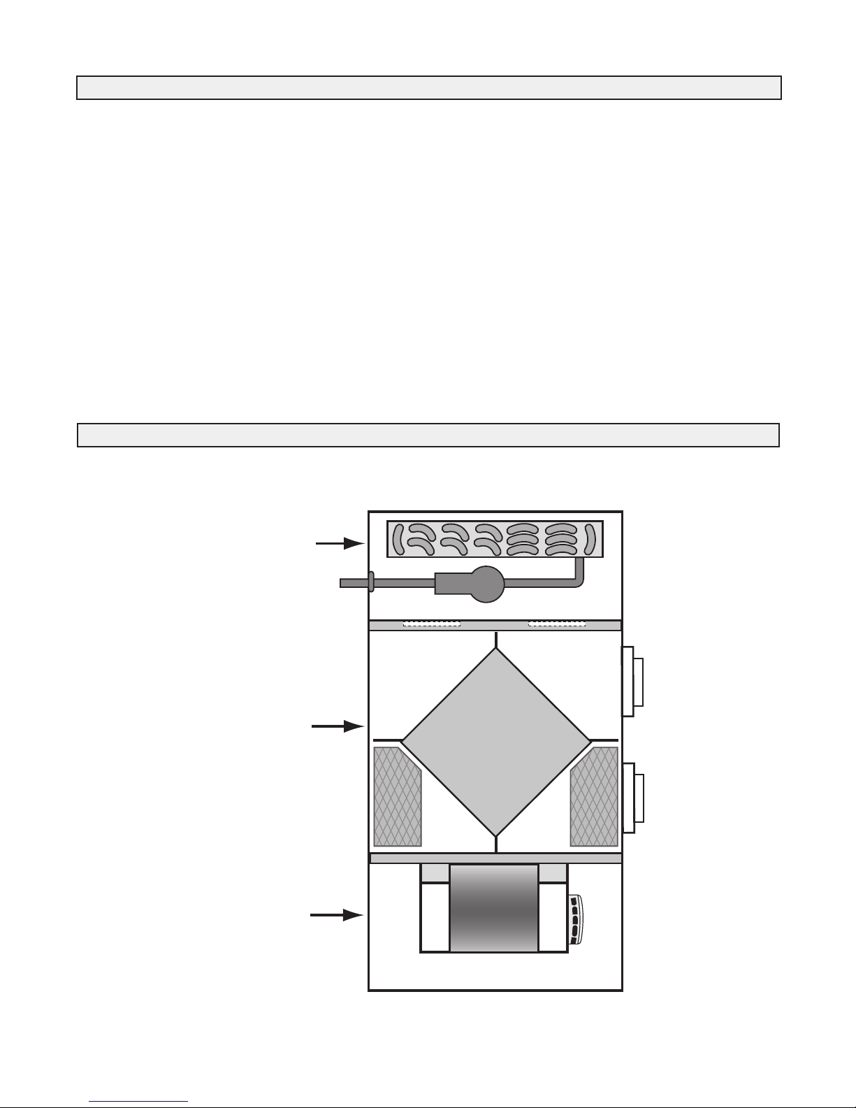
Hydronic Coil
and Pump
Compartment
Recovery Core
and Ventilation
Compartment
Aircom
Electronics
and Fan
Compartment
You will notice that the heated air in your home feels more
comfortable than air heated by a conventional furnace. One
reason for this is that LIFEBREATH's hydronically heated
air is uniform and temperate... no short blasts of hot air or
hot and cold temperature spikes. The air flowing from your
hot air vents will not feel as hot to the touch as air from a
conventional furnace.
With a high efficiency, adequately sized natural gas,
propane or oil hot water heater/boiler, you will always have
plenty of hot water for showers and baths, washing dishes
and clothes, and all other normal domestic hot water needs.
If there is an unusually high demand for hot water, such as
filling a large hot tub, then all you need to do is allow more
time for the task so the water heater/boiler can keep up to
its job of providing hot water for the heating system as well
as other household uses.
Overview of the Clean Air Furnace
Once it is correctly installed, safety will never be an issue
with your LIFEBREATH furnace. No flames, fumes or flue
gases to be concerned about. Your domestic hot water
heater/boiler now provides the heat source for your furnace.
This Operation and Installation Guide will help you learn
about your LIFEBREATH Clean Air Furnace quickly and
easily. The table of contents will show you where to find
information on every feature of this unit along with easy to
understand operating instructions. If, however, you do
encounter a question that is not covered in this Guide you
should call the LIFEBREATH dealer who installed your
furnace. Chances are that he will be able to give you a
satisfactory answer but if he is unable to do so then we
invite you to contact us directly.
Airia Brands Inc.
3

Description and Purpose
IMPORTANT NOTE
The purpose of this manual is to act as an installation guide
only for t h e LIFEBRE ATH Cle a n Air F u r n a c e.
Manufacturers' instructions for other components, such as
the water-heater/boiler, must be followed.
All national and local code requirements must be met when
installing a LIFEBREATH Clean Air Furnace. Be sure to
consult the proper authorities.
Note: Temperatures greater than 130°F (54°C) pose a seri-
ous risk of scalding individuals running domestic
hot water for potable use.
This appliance complies with IAS Canada Inc. Requirement
CR95-003, Additional Requirements for Fan Coil Units for
use with Potable Water Heaters.
All piping and components connected to this appliance shall
be suitable for use with potable water.
Toxic chemicals, such as used for boiler treatment, shall not
be introduced into the potable water heater system.
When using this system and the hot water for space heating
is set to a higher temperature than for other uses, an antiscald valve shall be used to ensure water for common use is
reduced in temperature to minimize a scalding hazard.
Combining two or more end uses such as space heating and
the heating of domestic hot water in a single system has the
potential to increase efficiency and reduce overall capital
costs. However, the proper design, installation, and commissioning of these systems are critical if these advantages
are to be realized.
This manual provides a guideline of good engineering practice in the desi gn, install atio n and commiss ioni ng of
Integrated Combo Systems. The guidelines in the manual
are designed for residential forced warm air Integrated
Combo Systems which utilize domestic water heaters or
boilers and the LIFEBREATH furnace. Heating and cooling
loads shall be calculated in accordance with recognized
Residential Heat Loss and Heat Gain Calculation methods.
Duct design shall comply with recognized Residential Air
System Design methods. This manual provides worksheets
to be used for the purpose of sizing residential water heaters
and the combo furnace.
The LIFEBREATH Clean Air Furnace is a volume ventilation system. Use the optional Lifebreath Bathroom Exhaust
System Kit (Part 99-CAF-BESKIT) if you wish to exhaust
from specific locations such as bathrooms.
Operation Heating/Cooling
When the room thermostat calls for heat, it activates a circulation pump located inside the Clean Air Furnace. This
pump delivers hot water from the water heater, through the
furnace coil and back to the water tank. Simultaneously, the
furnace blower switches on to high speed and will start circulating air across the coil, which picks up heat and delivers
it to the rest of your home.
Once the thermostat's temperature is reached the pump will
shut off, and the blower will return to its pre-set speed or
off.
Note: When the furnace blower is left running on low
speed the air in the home circulates continuously. When
the heat is called for the blower will automatically switch
to a higher speed. After the required hot air has been
delivered the blower will switch back to low speed.
When the thermostat calls for cooling (evaporator coil and
condensing unit required), the furnace blower activates to
high speed and the outdoor condenser unit is energized.
After the thermostat temperature is reached, the condensing
unit will shut off and the blower will return to its preset
speed or off.
Ventilation
The heat recovery ventilation (HRV) portion of the Clean
Air Furnace, is automatic. Once set, a desired amount of
fresh air will be drawn into the home while the furnace
blower is activated.
To reduce humidity, increased ventilation may be required
during heating season. An optional remote dehumidistat can
be installed. The dehumidistat will increase the speed of the
furnace blower to high and will return to its original setting
when humidity levels decrease. Your dehumidistat must be
switched off during warmer months. A quality humidifier
should be added if you wish to increase winter humidity
levels
Typically the air flow for ventilation will be set to 50 70cfm, for low sp e ed fu r n a ce op e r at ion, an d
100 - 150cfm at high speed. The pleated furnace filter
should be checked regularly and replaced as needed. The
HRV filter should be washed twice a year or more often if
needed.
Off Season Circulation Timer
All models are equipped with a circulation timer. It is normal operation for these models to automatically run the
circulation pump intermittently for a short period of time.
4
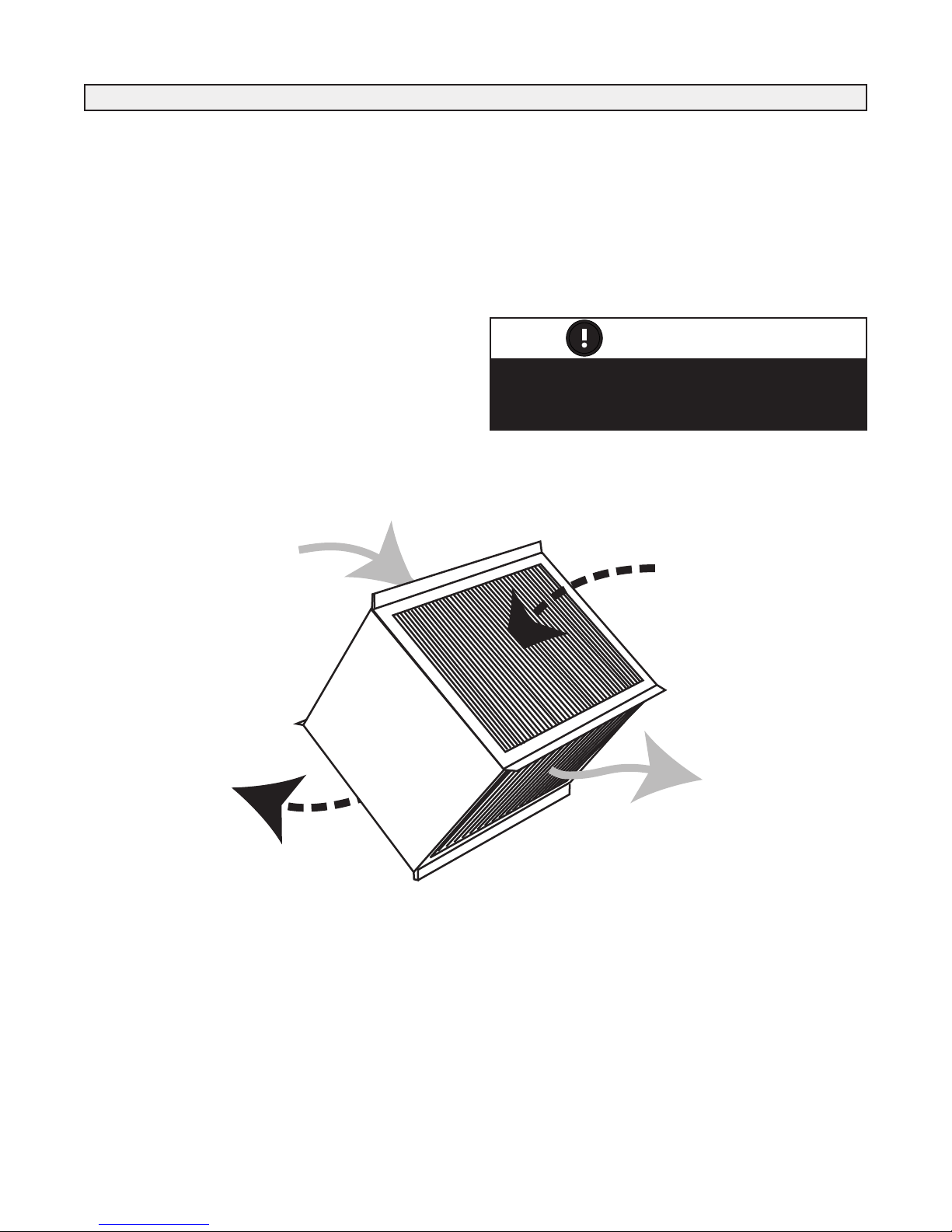
The Recovery Core
Stale Air
from Building
Stale Air
to Outside
Fresh
Outdoor Air
Fresh Air
to Building
The ERV - Enthalpic Core is not suitable for
climates where the outdoor temperature
drops below -4°C (25°F).
ATTENTION
HRV - Aluminum Core
A Heat Recovery Ventilator (HRV) is designed to provide
fresh air into a building while exhausting an equal amount
of stale air. During the winter months, the incoming cold
fresh air is warmed by utilizing the heat recovered from the
stale air before it is exhausted to the outdoors. During summer months when the indoor space is air conditioned, the
Heat Recovery Ventilator will help in cooling the incoming
fresh air with the stale air that is being exhausted.
ERV - Enthalpic Paper Core
An Energy Recovery Ventilator (ERV) is designed to provide fresh air into a building while exhausting an equal
amount of stale air. An ERV is designed for use in warm
humid areas with heavy air conditioning use. The ERV will
transfer both sensible and latent heat from the incoming
fresh air to the outgoing stale air thereby reducing the load
(due to ventilation) on the air conditioning system.
5
WATER HEATER
DOMESTIC HOT WATER
SUPPLY AIR
BLOWER
HEATING COIL
HRV/ERV CORE
CHECK
VALVE
RETURN AIR
COLD WATER INLET
ANTI-SCALD VALVE
(WHEN REQUIRED)
VALVE
(shut off)
VALVE
(shut off)
VALVE
(shut off)
VALVE
(balancing)
COOLING COIL
(OPTIONAL)
DRAIN
VALVE
EXPANSION TANK
(WHEN REQUIRED)
CHECK
VALVE
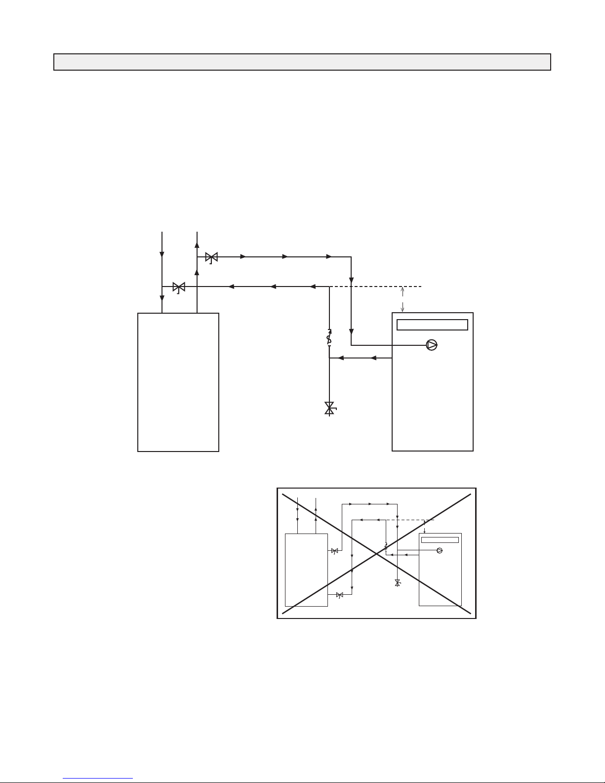
Combo System Basic Principles
ATTENTION
Check valves should always be installed in a
vertical rise with the flow of water shown.
Open and Closed Systems
Open and Closed systems both deliver hot water and space
heating.
Water systems that incorporate a pressure tank (i.e. well
systems) are normally Open Systems and most municipal
water systems are Closed Systems.
Closed Loop System
A system becomes closed when a Check Valve or a backflow prevention valve is installed in the cold water piping
upstream of the water heater.
A check valve will prevent water being relieved into the
cold water system due to pressure created when water is
heated in the water heater.
Drain Valve
A drain valve is required to allow the heating loop to be
drained for service or repair and to remove air from the
heating loop when commissioning a system. The drain
valve should be near the low point of the return piping system to be near the water heater. Ball, Globe or Gate Valves
are suitable for drain valves.
IMPORTANT
Refer to local codes, local bylaws and installation
manuals supplied with water heater before starting
any installation work.
This Check Valve minimizes
Thermo-Siphoning. Thermo
Siphoning is the cold water
backflowing through the
heating loop when domestic
hot water is called for.
Conventional
Cooling
(Not available
through Airia)
6
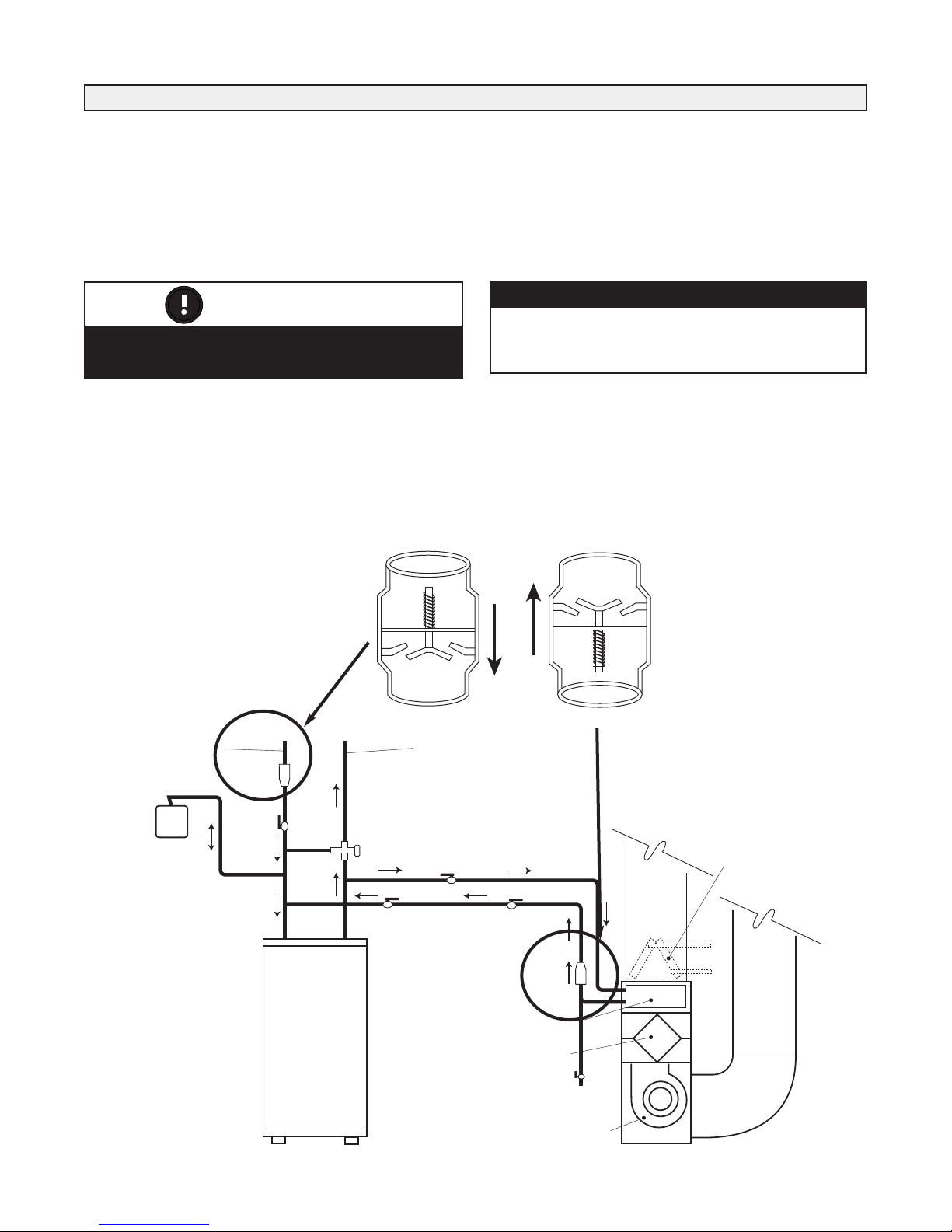
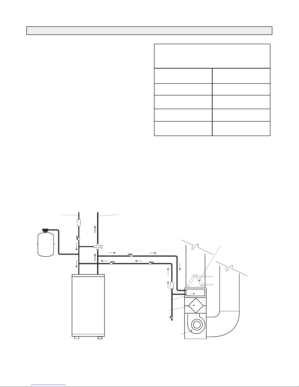
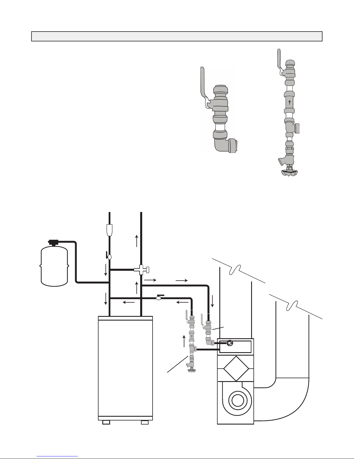
Plumbing
Water
Heater
Check
Valve
To
House
CAF
or
AH
Min. 12" (305 mm)above
top of CAF / AH
12"
Water
Heater
CAF
or
AH
Check
Valve
Min. 12" (305 mm)
above top of CAF / AH
To
House
12"
In order to improve serviceability of our products, the
check valve is included with our manual kit for field installation between the air-handler and hot water source.
The check valve should be installed in a vertical run of
pipe with the flow of water in an upward direction.
An arrow on the check valve indicates its correct orientation and must match the direction of water flow.
This will allow for ease of service to remove any installation debris or service required due to extended hard water
conditions.
Figure 1
Note: Take care during soldering to avoid debris or
solder from lodging in the check valve.
Note: It is critical to follow the piping configuration
shown. Maintain a minimum distance of 12” above
the CAF/AH. This will minimize thermal siphoning in
the combo system.
Figure 2
* It should be noted that problems have been observed when using the side
tappings on certain water heaters; therefore, it is strongly recommended to use the top
water tappings as indicated in Figure 1 to minimize thermal-siphoning and related
issues.
7
Plumbing
WATER HEATER
DOMESTIC HOT WATER
SUPPLY AIR
BLOWER
HEATING COIL
HRV/ERV CORE
CHECK
VALVE
RETURN AIR
COLD WATER INLET
ANTI-SCALD VALVE
(WHEN REQUIRED)
VALVE
(shut off)
VALVE
(shut off)
VALVE
(shut off)
VALVE
(balancing)
COOLING COIL
(OPTIONAL)
DRAIN
VALVE
EXPANSION TANK
(WHEN REQUIRED)
CHECK
VALVE
Expansion Tanks
Expansion tanks are required in addition to a Check Valve
for Closed Systems because pressure is created when water
is heated in the water heater.
The expansion tank has an air bladder which will contract to
relieve pressure in the system. The tank should always be
connected to the cold water piping between the water heater
shut off valve and the cold water inlet to the water heater.
Anti-Scald Valve
An anti-scald valve is required when the water heater thermostat is set above 140°F (60°C). Also, an anti-scald valve
may be required for all installations by the “authority having jurisdiction”. The valve is placed in the hot water supply
piping from the water heater downstream of the heating
loop connection and upstream of any domestic hot water
connection.
The purpose of the valve is to limit the maximum temperature available for domestic hot water by mixing hot water
from the water heater with cold water from the municipal
supply.
The Anti-Scald valve must be thermostatically controlled
and approved to the ASSE standard No. 1016 and 1017 for
use as an anti-scald device.
Time to Scald
(1st degree burns)
Temperature Time
120°F 8 min.
130°F 20 sec.
140°F 3 sec.
160°F <1 sec.
Closed Loop System
Conventional
Cooling
(Not available
through Airia)
8
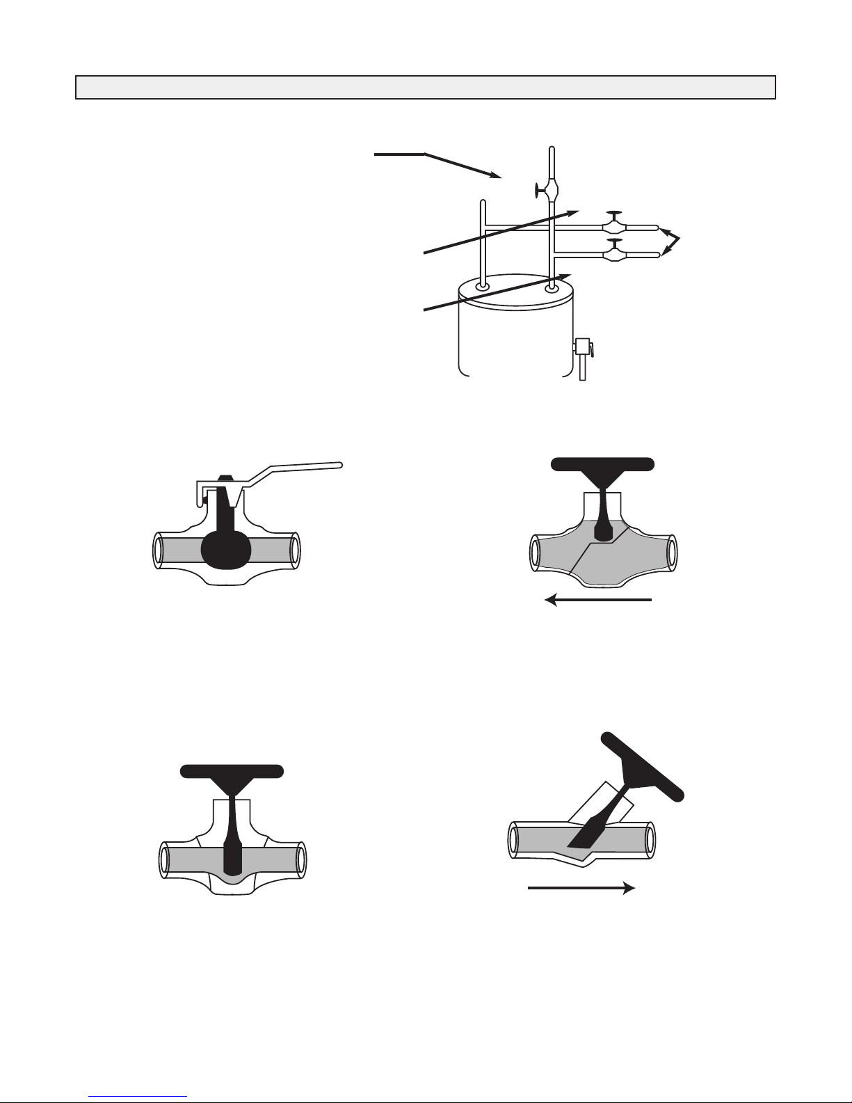
(a)
H
C
(b)
(c)
Supply
Return
Plumbing
Valves
(a) Located on the cold water side of the Heater.
This valve has the ability to isolate the hot water
(domestic and space heating) from the household cold
water supply. Every water heater requires this valve
regardless of space heating use.
(b) Located on the hot water supply side of the heating
loop, downstream of its connection to the domestic
water.
(c) Located on the return side of the heating loop upstream
of its connection to the domestic cold water.
These two
valves isolate
the heating
loop for
service or
repair.
Ball Valve
The Ball Valve can be used as a shut off or drain valve.
When in the open position, a full bore ball valve has very
little resistance to flow, and these valves tend to be both the
least expensive and the least susceptible to seizing over
time. Do not use reduced bore ball valves as they are very
restrictive to water flow.
Gate Valve
Globe Valve
The Globe valve can be used as a shut off, drain or throttling valve. Even in the open position, the valve is fairly
restrictive to flow. It has a much greater equivalent length
(resistance.) than the other types of valves.
Balancing (Throttling) Valve
The Gate Valve can be used as a shut off or drain valve.
When in the open position, there is very little resistance to
flow. Gate valves tend to be less expensive than other types
of valves but are susceptible to chatter (noise) and malfunction with age.
The Balancing (Throttling) Valve is used to reduce the
water flow rate and thereby increase the water temperature
drop. This is done to ensure proper activation of the water
heater thermostat.
A Globe Valve could also be used for Balancing (Throttling)
but has more resistance than the Balancing Valve.
9
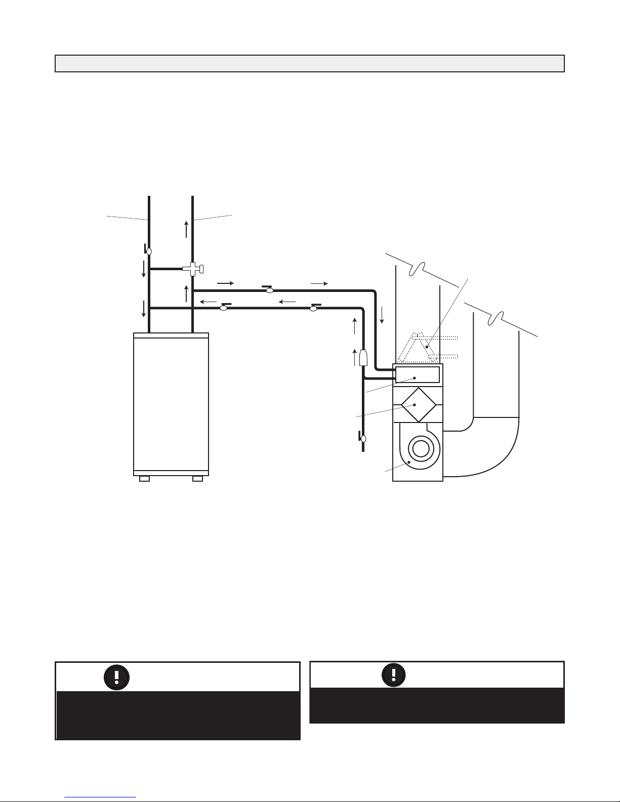
Plumbing
WATER HEATER
D
OMESTIC HOT WATER
SUPPLY AIR
BLOWER
CHECK
VALVE
R
ETURN AIR
C
OLD WATER INLET
ANTI-SCALD VALVE
(WHEN REQUIRED)
VALVE
(shut off)
VALVE
(shut off)
VALVE
(
shut off)
VALVE
(balancing)
C
OOLING COIL
(OPTIONAL)
DRAIN
VALVE
HEATING COIL
HRV/ERV CORE
Plumbing components and system
configuration may vary from diagrams
portrayed.
ATTENTION
Chemicals (such as boiler system additives)
cannot be added to a domestic hot water system.
ATTENTION
Call for Space Heating
There are two thermostats controlling every combo system,
the water heater thermostat (controlling the hot water temperature) and the room thermostat (controlling the room air
temperature).
Open Loop System
When the room thermostat calls for heat, the circulation
pump is activated. Hot water is then drawn from the top of
the water heater through the air handler, and then returned
to the water heater.
Conventional
Cooling
(Not available
through Airia)
Hot Water Temperature Drop
The water heater thermostat will initiate the water heater as
required as long as there is a 20°F (11°C) temperature drop
between the hot water supplied to the air handler and the
returning water.
A temperature drop less than 20°F (11°C) can cause the
water heater thermostat not to initiate. This will result in a
lower hot water supply temperature or poor space heating
performance with fluctuating domestic water temperatures.
Call for Domestic Hot Water and Space Heating
When both return water from the space heating loop and
new cold water (replacing domestic water being used)
enters the water heater, the mixed entering water is cool
enough to activate the thermostat quickly. In this situation,
the water heater must be capable of satisfying the combined
need for domestic hot water and space heating at the same
time.
10
Quick Connect Kit: PART# 99-CAF-PKit 1/2 or 3/4
WATER HEATER
SUPPLY AIR
RETURN AIR
Balancing
Valve
VALVE
(shut off)
WATER OUT
Assembly
EXPANSION TANK
(WHEN REQUIRED)
CHECK
VALVE
WATER IN
Assembly
KIT CONTENTS
WATER IN Assembly
WATER OUT Assembly
The pre-assembled, Quick Connect Kit shortens the
installation time. It provides an instant, easy assembly of the
major plumbing fittings required for a proper CAF/AH
installation.
The Quick Connect Kit includes the WATER IN and
WATER OUT assemblies. Kits are available in 1/2” and
3/4”sizes. Refer to the CAF/AH specification sheet located
in the Operation and Installation Manual to obtain the correct
size of water connections for the unit being installed.
Push-fit Fittings instantly make plumbing connections
thereby eliminating the need for solder. Be sure to read the
Push-fit Fitting Installation Instructions (included with the
Quick Connect Fitting Kit) before making any connections.
PART #99-CAF-PKit1/2
The 1/2” assembled kit.
PART #99-CAF-PKit3/4
The 3/4” assembled kit.
11

Plumbing
16
1
4
12
10
8
6
4
2
0
Capacity on U.S. gpm
S2 and S4 Models
1 2 4 6 8 10 12
To tal Head in Feet
L2 and L4 Models
1 2 4 6 8 10 12 14 16 18 20
16
14
12
10
8
6
4
2
0
Capacity on U.S. gpm
To tal Head in Feet
Air System
A circulation fan draws cool house air at approx. 70°F
(21°C) from the return ductwork, forces it through the water
coil where it is heated, and then distributes it to the various
rooms of the house through the supply ductwork.
Water System Pressures
Within the water system of an Integrated Combo system, a
designer/installer must understand the following terms:
1. Hot water supply temperature (EWT)
2. Hot water flow rate (GPM)
3. Air handler return temperature
4. Air handler flow rate (CFM)
Head Pressure
Head pressure is the pressure created by the circulation
pump to push water through the piping system. It is this
pressure which is used to overcome the resistance to water
flow (friction) caused by the water pipe and fittings. It is
similar in concept to the external static pressure in an air
duct system. Head pressure is measured in feet of water
(millimeters of water).
NOTE
The vertical height of the heating loop does not
impact on th e he a d p r e ssure as the pr e s s ur e
required to push the water up the vertical height is
offset by the weight of the water in the vertical drop
on the other side of the heating loop.
Pressure Drop (PD)
Pressure drop (PD) is the reduction in total pressure caused
by components added to a piping system such as coils,
valves, and fittings. The measurement of pressure drop is
the difference in pressure on the inlet side of the component
and the outlet side. Pressure drop is measured in feet of
water (millimeters of water).
When connecting the water lines for heating loop (air handler) to the domestic water system, the pipes should be
connected with a “tee” to the side of a vertical domestic
water pipe or the bottom of a horizontal domestic water
pipe. This is to help prevent air from entering the heating
loop. The connections should be as near as practical to the
water heater.
Water Pump Performance Specifications
Water Flow Rate
Water flow rate is the amount of water flowing in the system. It is directly related to the head pressure and the
resistance to flow. Flow rate is measured in gallons per
minute (liters per minute).
The circulation pump is factory installed within the air handler. The water flow rate will vary depending on the pumps
performance and the head pressure (resistance) of the complete heating loop system.
The piping and fittings used to connect the water heater and
air handler must be sized to handle the volume of hot water
required by the air handler within the pressure limitations of
the circulation pump. All piping, fittings solders, and fluxes
must be acceptable for use with domestic hot water.
12

Plumbing
Air Handler Output Capacity
There are four factors that will significantly affect the
heating output of the air handler.
They are:
• Hot water supply temperature (EWT)
• Hot water flow rate (GPM)
• Air Handler return air temperature
• Air Handler air flow rate (CFM)
Hot Water Supply Temperature
The hot water supply temperature is controlled by the water
heater thermostat. This is set by the installing contractor to
provide the required temperature at the hot water outlet of
the water heater.
The hot water supply temperature is typically 140°F (60°C).
If this temperature must be increased to achieve higher
outputs from the furnace an anti-scald valve must be used to
prevent domestic hot water temperatures above 140°F
(60°C). The manufacturer of the Hot water Tank should be
consulted for temperatures higher than 140°F.
It is important that a warning label be placed near the water
heater thermostat telling the homeowner not to change the
thermostat setting. The label is included with the furnace.
Hot Water Flow Rate
The hot water entering the water coil is the source of heat to
the air handler. The effect of changing the amount of water
entering the c o i l is t h e sa m e a s ch a n g i n g th e w a t e r
temperature. As water flow is reduced, the output of the air
handler and the air temperature rise will both be lowered.
Air Handler Return Air Temperature
The return air temperat ure e ntering the air handler is
approx. 60°F (33°C) below the hot water inlet temperature.
If the return air temperature entering the air handler is
reduced, more heat transfer will occur and the output of the
air handler will increase.
NOTE
Although the water in the combo system is
pressurized by the domestic water system, the
pump is required to create water flow in the heating
loop. The domestic water system applies the same
pressure to the supply and return sides of the
heating loop.
Air Handler Air Flow Rate
The air entering the air handler can only be warmed by the
temperature difference between the hot water and the cool
air. As the volume (CFM (L/s)) of air is reduced, the amount
of heat which can be transferred is also reduced.
Air Handler Temperature Rise
In a fuel fired furnace, the combustion gases can be 1000°F
(538°C) above the return air temperature. These units
typically have a temperature rise from 50°F (10°C) to 90°F
(32°C) and therefore delivers air at the diffuser at 120°F
(49°C) to 160°F (71°C).
Wit h an I n t e g rated C o mb o S y s t e m , th e hot w a t er
temp e r a t u r e is a p p r o x . 130°F ( 5 4 °C) w h i c h is 6 0 ° F
(15.5°C) above the return air temperature. These units
typically have a temperature rise of 35°F (2°C) to 40°F
(4°C) and therefore would deliver air at the diffuser at
approximately 105°F (40.5°C) to 110°F (43°C).
Room Thermostat
The ro o m ther m o s t a t cont r o l s both the wa t er
circulation pump and the air circulation fan. It should be on
a centrally located, inside wall away from any source of
heat such as diffusers, appliances and direct sunlight.
Energy Saving Room Thermostat
A set back thermostat or “smart stat” can be used with a
combo system, but care must be taken in the timing of the
temperature changes. The timing of morning warm up
should be early enough that the desired air temperature has
been reached before the people begin to use domestic hot
water. The highest demand for space heating is during the
morning warm up and the highest demand for domestic hot
water is during morning showers. Even if the water heater
is properly sized, it may not be able to meet this combined
load. Therefore, large set backs should be avoided.
Design vs. Field Conditions
The factors discussed between design parameters and actual
field conditions can impact greatly on output capacity.
Therefore, it is important to do a thorough and complete
commissioning of the integrated combo system to ensure
the design parameters are met.
13
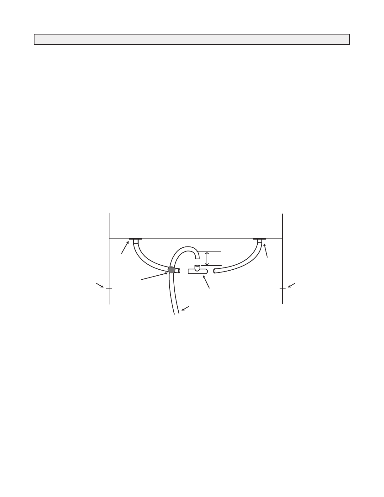
Plumbing
DRAIN
SPOUT
TAPE
THROUGH KNOCKOUT
TO DRAIN
TEE
CONNECTOR
DRAIN
SPOUT
2” (50 mm)
KNOCKOUT
KNOCKOUT
Drain Line
The ventilation portion of the Clean Air Furnace has two
drain pans for removing condensation, which may occur on
the heat recovery core during cold weather.
Piping
The hot water piping between the hot water tank and the
Clean Air Furnace should be new copper type, and should
not be treated with chemicals, sealant or anything else, that
will interfere with the purity of the potable water. Only nonlead, low temperature solder is permitted for sealing copper
joints.
Where possible the length of pipe should not exceed 200'
total equivalent length. Any piping running through unconditioned space must be insulated to prevent heat loss, and
possible freezing of the line.
HRV Drain Line Diagram
Look inside the furnace and locate the pump. Attach the
"Hot Water In" (Supply) to the pipe running to the pump.
Attach the "Hot Water Out" (Return) to the pipe running to
the coil. Do not reverse these lines, as this will cause the
unit to malfunction.
For piping conventional water heaters, connections to and
from the Clean Air Furnace to the water tank should be
made at the point where the pipes leave the tank vertically.
A "T" fitting used in each vertical line, with the Clean Air
Furnace piping connected to the horizontal side of this fitting, will work best in avoiding air locks in the circulation
pump of the furnace.
*Note: Remove shipping block from underneath pump and
discard.
14
 Loading...