

Lifebreath AH-U-S4A-24-P16, AH-U-L2B-48-P16, AH-U-L4A-36-P16, AH-U-S2A-30-P16, AH-U-L2A-36-P16 Operation, Sizing And Installation Manual
Page 1

Operation, Sizing and Installation Manual
AIR HANDLER
MANUFACTURED WITH
AIRCOM ELECTRONICS
Models
AH-U-S4A-24-P16 (E16)
AH-U-L4A-36-P16 (E16)
AH-U-S2A-30-P16 (E16)
AH-U-L2A-36-P16 (E16)
AH-U-L2B-48-P16 (E16)
* LEAVE FOR HOMEOWNER
NOTE: Due to ongoing research and product development, specifications,
ratings and dimensions are subject to change without notice.
69-AH
091517
Page 2
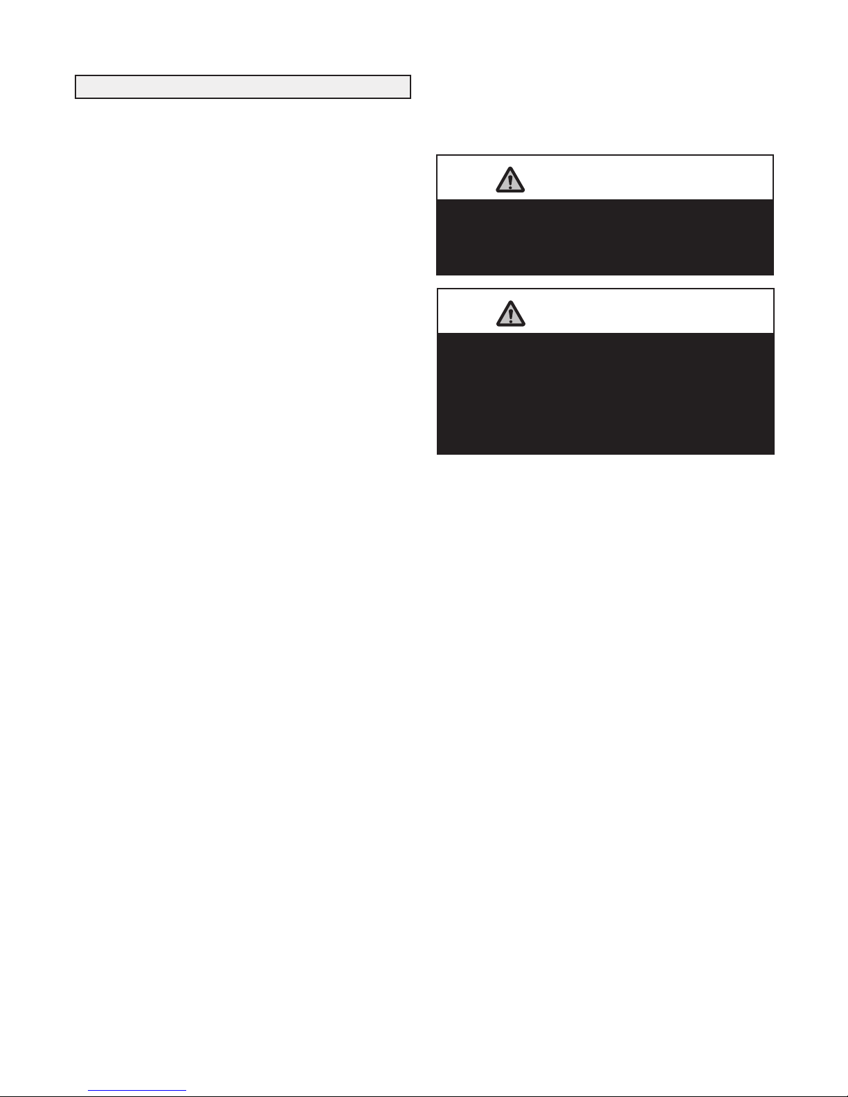
Table of Contents
Air Condition coil freezing can damage the
hydronic coil of the Air Handler.
Install a Freeze Thermostat Kit to your air
conditioning coil to prevent coil freeze up. Check
with your air conditioner distributor to obtain a
Freeze Thermostat Kit.
ATTENTION
The Air Handler hydronic coil is not to be used for
chilled water applications where condensation is
expected.
ATTENTION
Introduction.......................................................................3
Overview of the AH..........................................................3
Description and Purpose ..................................................4
Operation Heating/Cooling...............................................4
Combo System Basic Principles .......................................5
Plumbing......................................................................6-11
Installation ......................................................................12
Function and Controls ...............................................13-14
Aircom Relays ................................................................15
Start-Up Procedure .........................................................15
Troubleshooting ..............................................................16
Model Number Nomenclature Breakdown .....................17
Specifications ............................................................18-22
Work Sheets...............................................................23-28
Wiring Diagrams .......................................................29-30
2
Page 3
Introduction
Hydronic Coil
and Pump
Compartment
Aircom
Electronics
and Fan
Compartment
You will notice that the heated air in your home feels more
comfortable than air heated by a conventional furnace. One
reason for this is that LIFEBREATH's hydronically heated
air is uniform and temperate... no short blasts of hot air or
hot and cold temperature spikes. In this regard, the air flowing from your hot air vents will not feel as hot to the touch
as air from a conventional furnace.
With a high efficiency, adequately sized natural gas,
propane or oil hot water heater/boiler, you will always have
plenty of hot water for showers and baths, washing dishes
and clothes, and all other normal domestic hot water needs.
If there is an unusually high demand for hot water, such as
filling a large hot tub, than all you need to do is allow more
time for the task so the water heater/boiler can keep up to
its job of providing hot water for the heating system as well
as other household uses.
Overview of the Air Handler
Once it is correctly installed, safety will never be an issue
with your LIFEBREATH air handler. No flames, fumes or
flue gases to be concerned about. Your domestic hot water
heater/boiler now provides the heat source for your furnace.
This Operating and Installation Guide will help you learn
about your LIFEBREATH Air Handler quickly and easily.
The table of contents will show you where to find informati on on ev ery feature of this un it along with e asy t o
understand operating instructions. If, however, you do
encounter a question that is not covered in this Guide you
should call the LIFEBREATH dealer who installed your
furnace. Chances are that he will be able to give you a satisfactory answer but if he is unable to do so then we invite
you to contact us directly.
Airia Brands Inc.
3
Page 4

Description and Purpose
IMPORTANT NOTE
The purpose of this manual is to act as an installation guide
only for the LIFEBREATH Air Handler. Manufacturers'
instructions f or other components, such as the waterheater/boiler, must be followed.
All national and local code requirements must be met when
installing a LIFEBREATH Air Handler. Be sure to consult
the proper authorities.
Note: Temperatures greater than 130°F (54°C) pose a seri-
ous risk of scalding individuals running domestic
hot water for potable use.
This appliance complies with IAS Canada Inc. Requirement
CR95-003, Additional Requirements for Fan Coil Units for
use with Potable Water Heaters.
All piping and components connected to this appliance shall
be suitable for use with potable water.
Toxic chemicals, such as used for boiler treatment, shall not
be introduced into the potable water heater system.
When using this system, and water for space heating is
Operation Heating/Cooling
required to be at a higher temperature than for other uses, an
anti-scald valve shall be used to ensure water for other uses
is reduced in temperature to minimize a scald hazard potential.
Combining two or more end uses such as space heating and
the heating of domestic hot water in a single system has the
potential to increase efficiency and reduce overall capital
costs. However, the proper design, installation, and commissioning of these systems are critical if these advantages
are to be realized.
This manual provides a guideline of good engineering practice i n the design, i nstallation a nd commissioning of
Integrated Combo Systems. The guidelines in the manual
are designed for residential forced warm air Integrated
Combo Systems which utilize domestic water heaters or
boilers and the LIFEBREATH furnace. Heating and cooling
loads shall be calculated in accordance with recognized
Residential Heat Loss and Heat Gain Calculation methods.
Duct design shall comply with recognized Residential Air
System Design methods.
When the room thermostat calls for heat, it activates a circulation pump located inside the Air Handler. This pump
delivers hot water from the water heater, through the furnace coil and back to the water tank. Simultaneously, the
furnace blower switches on to high speed and will start circulating air across the coil, which picks up heat and delivers
it to the rest of your home.
Once the thermostat's temperature is reached the pump will
shut off, and the blower will return to its pre-set speed or
off.
Note: When the furnace blower is left running on low
speed the air in the home circulates continuously. When
the heat is called for the blower will automatically switch
to a higher speed. After the required hot air has been
delivered the blower will switch back to low speed.
When the thermostat calls for cooling (evaporator coil and
condensing unit required), the furnace blower activates to
high speed and the outdoor condenser unit is energized.
After the thermostat temperature is reached, the condensing
unit will shut off and the blower will return to its preset
speed or off.
Off Season Circulation Timer
All models are equipped with a circulation timer. It is normal operation for these models to automatically run the
circulation pump for a short period of time intermittently.
4
Page 5
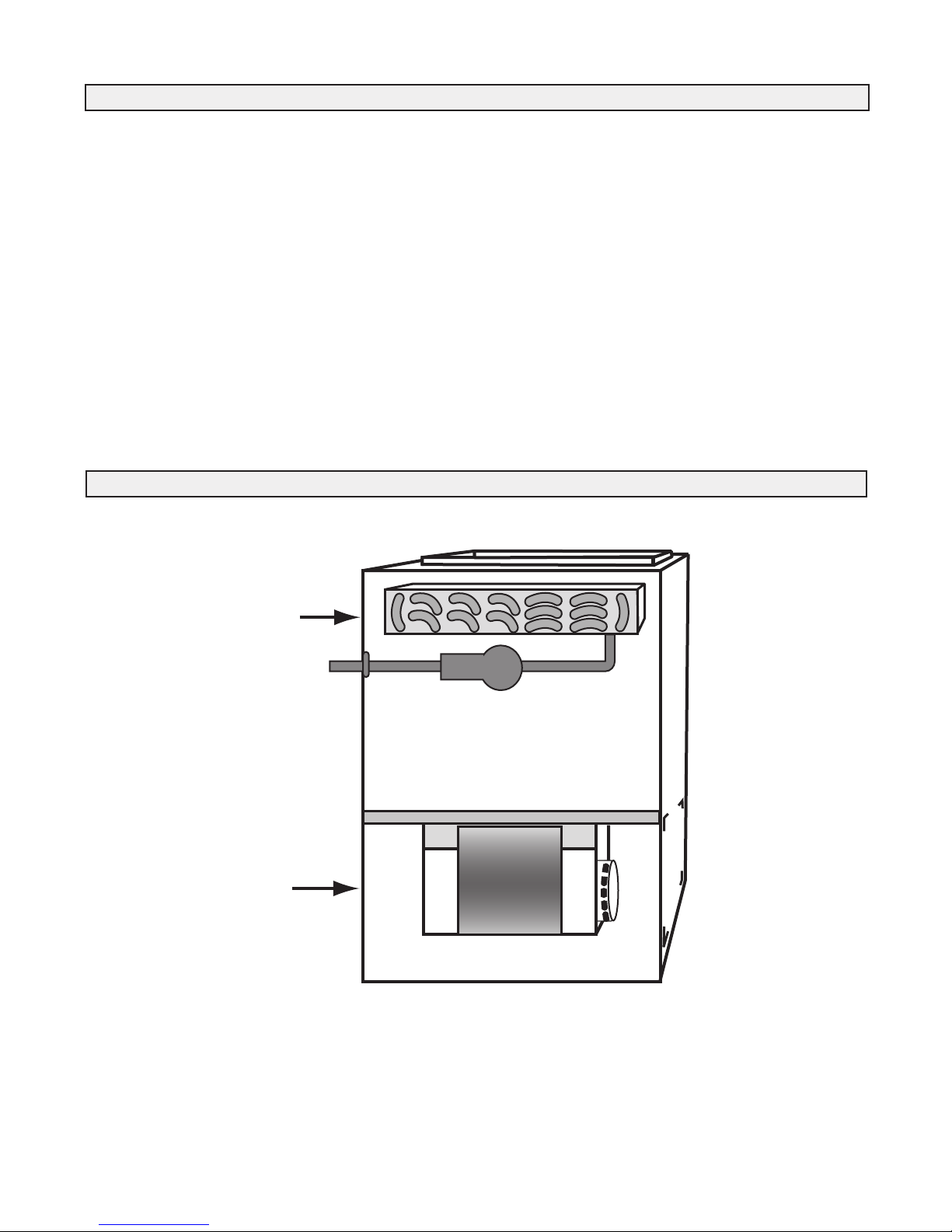
WATER HEATER
DOMESTIC HOT WATER
SUPPLY AIR
BLOWER
HEATING COIL
RETURN AIR
COLD WATER INLET
ANTI-SCALD VALVE
(WHEN REQUIRED)
VALVE
(shut off)
VALVE
(shut off)
VALVE
(shut off)
VALVE
(balancing)
COOLING COIL
(OPTIONAL)
DRAIN
VALVE
EXPANSION TANK
OR OTHER MEANS
(WHEN REQUIRED)
CHECK
VALVE
Combo System Basic Principles
ATTENTION
Check valves should always be installed in a
vertical rise with the flow of water shown.
Open and Closed Systems
Open and Closed systems both deliver hot water and space
heating.
Water systems that incorporate a pressure tank (i.e. well
systems) are normally Open Systems and most municipal
water systems are Closed Systems.
Closed Loop System
A system becomes closed when a Check Valve or a backflow prevention valve is installed in the cold water piping
upstream of the water heater.
A check valve will prevent water being relieved into the
cold water system due to pressure created when
water is heated in the water heater.
Drain Valve
A drain valve is required to allow the heating loop to be
drained for service or repair and to remove air from the
heating loop when commissioning a system. The drain
valve should be near the low point of the return piping system to be near the water heater. Ball, Globe or Gate Valves
are suitable for drain valves.
IMPORTANT
Refer to local codes, local bylaws and installation
manuals supplied with water heater before starting
any installation work.
This Check Valve
minimizes ThermoSiphoning. Thermo
Siphoning is the cold
water backflowing
through the heating
loop when domestic
hot water is called
for.
5
Conventional
Cooling Coil
(Not available
through Airia)
Page 6
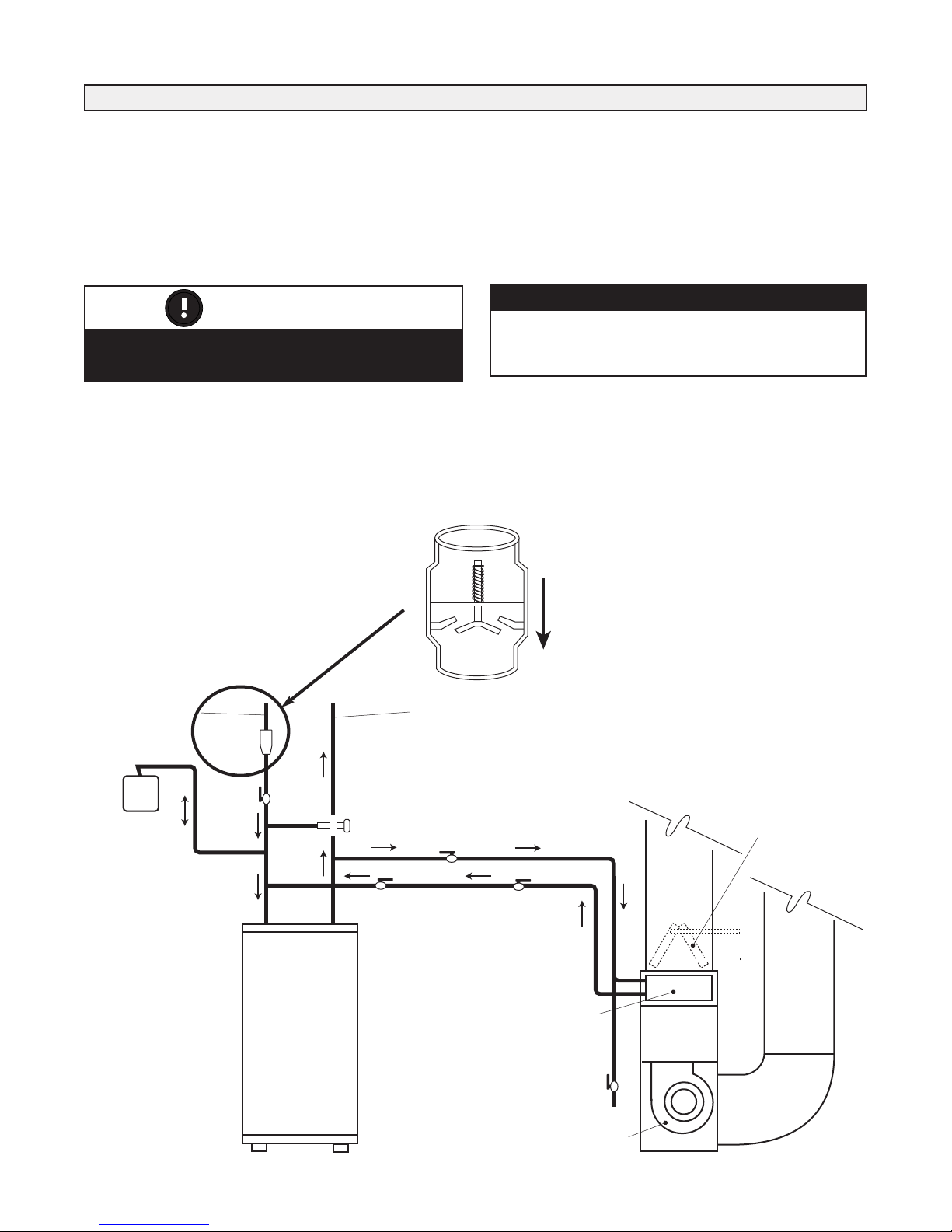
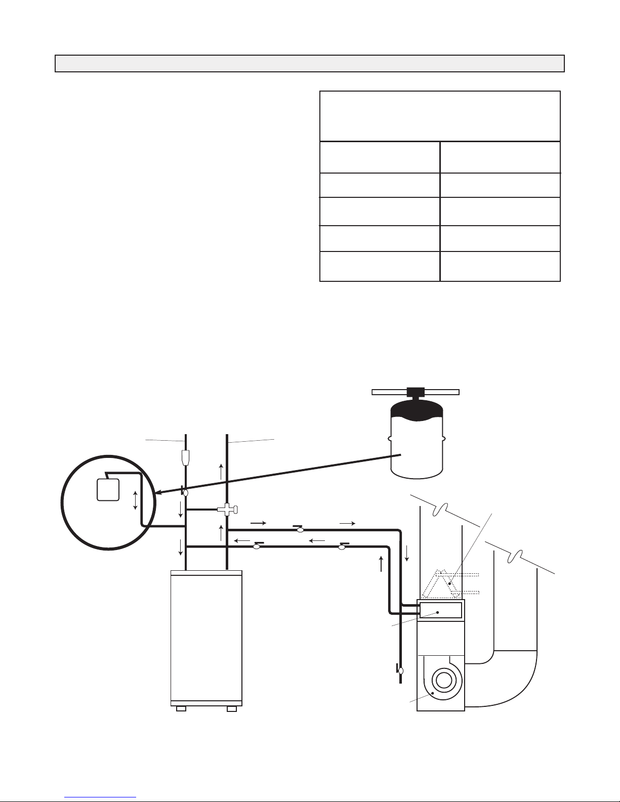
Plumbing
Water
Heater
To
House
CAF
or
AH
Min. 12" (305 mm)
above top of
CAF / AH
12"
Water
Heater
CAF
or
AH
Min. 12" (305 mm)
above top of
CAF / AH
To
House
12"
There is an integrated check valve in the coil assembly of
the CAF / AH unit.
Figure 1
Note: Take care during soldering to avoid debris or
solder from lodging in the check valve.
Note: It is critical to follow the piping configuration
shown. Maintain a minimum distance of 12” above
the CAF/AH. This will minimize thermal siphoning in
the combo system.
Figure 2
* It should be noted that problems have been observed when using the side
tappings on certain water heaters; therefore, it is strongly recommended to use the top
water tappings as indicated in Figure 1 to minimize thermal siphoning and related
issues.
6
Page 7
Plumbing
WATER HEATER
DOMESTIC HOT WATER
SUPPLY AIR
BLOWER
HEATING COIL
RETURN AIR
COLD WATER INLET
ANTI-SCALD VALVE
(WHEN REQUIRED)
VALVE
(shut off)
VALVE
(shut off)
VALVE
(shut off)
VALVE
(balancing)
COOLING COIL
(OPTIONAL)
DRAIN
VALVE
EXPANSION TANK
OR OTHER MEANS
(WHEN REQUIRED)
CHECK
VALVE
Expansion Tanks
Expansion tanks are required in addition to a Check Valve
for Closed Systems because pressure is created when water
is heated in the water heater.
The expansion tank has an air bladder which will contract to
relieve pressure in the system. The tank should always be
connected to the cold water piping between the water heater
shut off valve and the cold water inlet to the water heater.
Anti-Scald Valve
An anti-scald valve is required when the water heater thermostat is set above 140°F (60°C). Also, an anti-scald valve
may be required for all installations by the “authority having jurisdiction”. The valve is placed in the hot water supply
piping from the water heater downstream of the heating
loop connection and upstream of any domestic hot water
connection.
The purpose of the valve is to limit the maximum temperature available for domestic hot water by mixing hot water
from the water heater with cold water from the municipal
supply.
The Anti-Scald valve must be thermostatically controlled
and approved to the ASSE standard No. 1016 and 1017 for
use as an anti-scald device.
Time to Scald
(1st degree burns)
Temperature Time
120°F (49°C) 8 min.
130°F (54°C) 20 sec.
140°F (60°C) 3 sec.
160°F (71°C) <1 sec.
Closed Loop System
Conventional
Cooling Coil
(Not available
through Airia)
7
Page 8
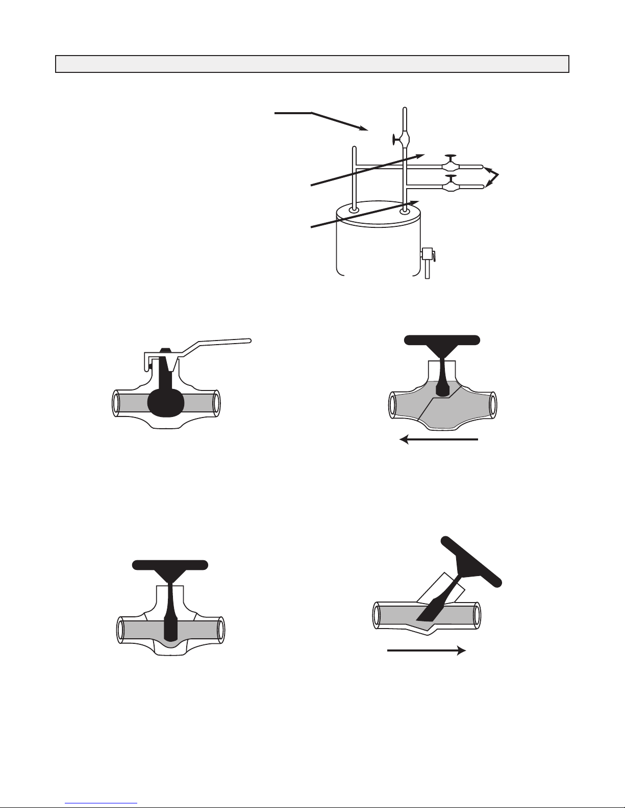
(a)
H
C
(b)
(c)
Supply
Return
Plumbing
Valves
(a) Located on the cold water side of the Heater.
This valve has the ability to isolate the hot water
(domestic and space heating) from the household cold
water supply. Every water heater requires this valve
regardless of space heating use.
(b) Located on the hot water supply side of the heating
loop, downstream of its connection to the domestic
water.
(c) Located on the return side of the heating loop upstream
of its connection to the domestic cold water.
These two
valves isolate
the heating
loop for
service or
repair.
Ball Valve
The Ball Valve can be used as a shut off or drain valve.
When in the open position, a full bore ball valve has very
little resistance to flow, and these valves tend to be both the
least expensive and the least susceptible to seizing over
time. Do not use reduced bore ball valves as they are very
restrictive to water flow.
Gate Valve
Globe Valve
The Globe valve can be used as a shut off, drain or throttling valve. Even in the open position, the valve is fairly
restrictive to flow. It has a much greater equivalent length
(resistance.) than the other types of valves.
Balancing (Throttling) Valve
The Gate Valve can be used as a shut off or drain valve.
When in the open position, there is very little resistance to
flow. Gate valves tend to be less expensive than other types
of valves but are susceptible to chatter (noise) and malfunction with age.
The Balancing (Throttling) Valve is used to reduce the
water flow rate and thereby increase the water temperature
drop. This is done to ensure proper activation of the water
heater thermostat.
A Globe Valve could also be used for Balancing (Throttling)
but has more resistance than the Balancing Valve.
8
Page 9
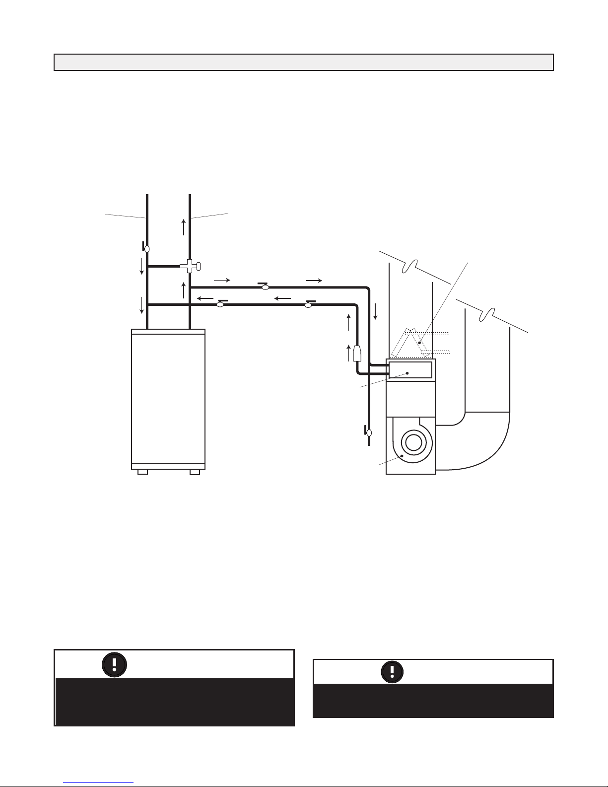
Plumbing
WATER HEATER
DOMESTIC HOT WATER
S
UPPLY AIR
BLOWER
CHECK
VALVE
R
ETURN AIR
COLD WATER INLET
ANTI-SCALD VALVE
(WHEN REQUIRED)
VALVE
(shut off)
VALVE
(shut off)
V
ALVE
(shut off)
VALVE
(balancing)
COOLING COIL
(
OPTIONAL)
DRAIN
VALVE
HEATING COIL
Plumbing components and system
configuration may vary from diagrams
portrayed.
ATTENTION
Chemicals (such as boiler system additives)
cannot be added to a domestic hot water system.
ATTENTION
Call for Space Heating
There are two thermostats controlling every combo system,
the water heater thermostat (controlling the hot water temperature) and the room thermostat (controlling the room air
temperature).
Open Loop System
When the room thermostat calls for heat, the circulation
pump is activated. Hot water is then drawn from the top of
the water heater through the air handler, and then returned
to the water heater.
Hot Water Temperature Drop
The water heater thermostat will initiate the water heater as
required as long as there is a 20°F (11°C) temperature drop
between the hot water supplied to the air handler and the
returning water.
A temperature drop less than 20°F (11°C) can cause the
water heater thermostat not to initiate. This will result in a
lower hot water supply temperature or poor space heating
performance with fluctuating domestic water temperatures.
Call for Domestic Hot Water and Space Heating
When both return water from the space heating loop and
new cold water (replacing domestic water being used)
enters the water heater, the mixed entering water is cool
enough to activate the thermostat quickly. In this situation,
the water heater must be capable of satisfying the combined
need for domestic hot water and space heating at the same
time.
9
Page 10

Quick Connect Kit: PART# 99-CAF-PKit 1/2 or 3/4
KIT CONTENTS
WATER IN Assembly
WATER OUT Assembly
WATER HEATER
SUPPLY AIR
RETURN AIR
Balancing
Valve
VALVE
(shut off)
WATER OUT
Assembly
EXPANSION TANK
(WHEN REQUIRED)
CHECK
VALVE
WATER IN
Assembly
The pre-assembled, Quick Connect Kit shortens the
installation time. It provides an instant, easy assembly of the
major plumbing fittings required for a proper CAF/AH
installation.
The Quick Connect Kit includes the WATER IN and
WATER OUT assemblies. Kits are available in 1/2” and
3/4”sizes. Refer to the CAF/AH specification sheet located
in the Operation and Installation Manual to obtain the correct
size of water connections for the unit being installed.
Push-fit Fittings instantly make plumbing connections
thereby eliminating the need for solder. Be sure to read the
Push-fit Fitting Installation Instructions (included with the
Quick Connect Fitting Kit) before making any connections.
PART #99-CAF-PKit1/2
The 1/2” assembled kit.
PART #99-CAF-PKit3/4
The 3/4” assembled kit.
10
Page 11

Plumbing
Air System
A circulation fan draws cool house air at approx. 70°F
(21°C) from the return ductwork, forces it through the water
coil where it is heated, and then distributes it to the various
rooms of the house through the supply ductwork.
Water System Pressures
Within the water system of an Integrated Combo system,
there are three terms that the designer/installer must understand. These are:
• Head pressure
• Water flow rate
• Pressure drop
Head Pressure
Head pressure is the pressure created by the circulation
pump to push water through the piping system. It is this
pressure which is used to overcome the resistance to water
flow (friction) caused by the water pipe and fittings. It is
similar in concept to the external static pressure in an air
duct system. Head pressure is measured in feet of water
(millimeters of water).
NOTE
The vertical height of the heating loop does not
impact on t h e head pressu r e a s the pressure
required to push the water up the vertical height is
offset by the weight of the water in the vertical drop
on the other side of the heating loop.
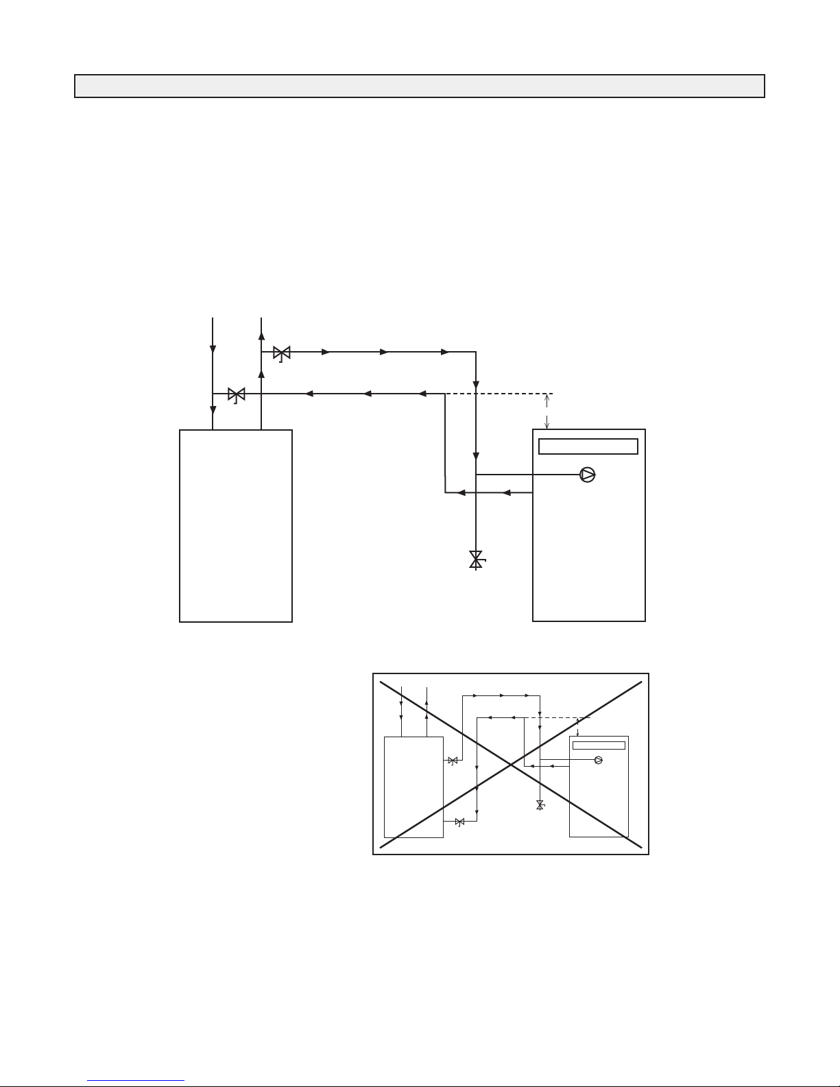
Pressure Drop (PD)
Pressure drop (PD) is the reduction in total pressure caused
by components added to a piping system such as coils,
valves, and fittings. The measurement of pressure drop is
the difference in pressure on the inlet side of the component
and the outlet side. Pressure drop is measured in feet of
water (millimeters of water).
When connecting the water lines for heating loop (air handler) to the domestic water system, the pipes should be
connected with a “tee” to the side of a vertical domestic
water pipe or the bottom of a horizontal domestic water
pipe. This is to help prevent air from entering the heating
loop. The connections should be as near as practical to the
water heater.
Water Pump Performance Specifications
Water Flow Rate
Water flow rate is the amount of water flowing in the
system. It is directly related to the head pressure and the
resistance to flow. Flow rate is measured in gallons per
minute (liters per minute).
The circulation pump is factory installed within the air handler. The water flow rate will vary depending on the pumps
performance and the head pressure (resistance) of the
complete heating loop system.
The piping and fittings used to connect the water heater and
air handler must be sized to handle the volume of hot water
required by the air handler within the pressure limitations of
the circulation pump. All piping, fittings solders, and fluxes
must be acceptable for use with domestic hot water.
11
Page 12

Plumbing
Air Handler Output Capacity
There are four factors that will significantly affect the heating output of the air handler.
They are:
• Hot water supply temperature (EWT)
• Hot water flow rate (GPM)
• Air Handler return air temperature
• Air Handler air flow rate (CFM)
Hot Water Supply Temperature
The hot water supply temperature is controlled by the water
heater thermostat. This is set by the installing contractor to
provide the required temperature at the hot water outlet of
the water heater.
The hot water supply temperature is typically 140°F (60°C).
If this temperature must be increased to achieve higher outputs from the furnace an anti-scald valve must be used to
prevent domestic hot water temperatures above 140°F
(60°C). The manufacturer of the Hot water Tank should be
consulted for temperatures higher than 140°F (60°C).
It is important that a warning label be placed near the water
heater thermostat telling the homeowner not to change the
thermostat setting. The label is included with the furnace.
Hot Water Flow Rate
The hot water entering the water coil is the source of heat to
the air handler. The effect of changing the amount of water
entering the coil is the same as changing the water temperature. As water flow is reduced, the output of the air handler
and the air temperature rise will both be lowered.
Air Handler Return Air Temperature
The return air temperatur e ente ring the air handler is
approx. 60°F (33°C) below the hot water inlet temperature.
If the return air temperature entering the air handler is
reduced, more heat transfer will occur and the output of the
air handler will increase.
NOTE
Although the water in the combo system is pressurized by
the domestic water system the pump is required to create
water flow in the heating loop. The domestic water system
applies the same pressure to the supply and return sides
of heating loop.
Air Handler Air Flow Rate
The air entering the air handler can only be warmed by the
temperature difference between the hot water and the cool
air. As the volume (CFM (L/s)) of air is reduced, the amount
of heat which can be transferred is also reduced.
Air Handler Temperature Rise
In a fuel fired furnace, the combustion gases can be 1000°F
(538°C) above the return air temperature. These units typically have a temperature rise from 50°F (10°C) to 90°F
(32°C) and therefore delivers air at the diffuser at 120°F
(49°C) to 160°F (71°C).
With an Integrated Combo System, the hot water temperature is approx. 130°F (54°C) which is 60°F (15.5°C) above
the return air temperature. These units typically have a temperature rise of 35°F (2°C) to 40°F (4°C) and therefore
would deliver air at the diffuser at approximately 105°F
(40.5°C) to 110°F (43°C).
Room Thermostat
The room th e r m o st a t controls bo t h the water
circulation pump and the air circulation fan. It should be on
a centrally located, inside wall away from any source of
heat such as diffusers, appliances and direct sunlight.
Energy Saving Room Thermostat
A set back thermostat or “smart stat” can be used with a
combo system, but care must be taken in the timing of the
temperature changes. The timing of morning warm up
should be early enough that the desired air temperature has
been reached before the people begin to use domestic hot
water. The highest demand for space heating is during the
morning warm up and the highest demand for domestic hot
water is during morning showers. Even if the water heater
is properly sized, it may not be able to meet this combined
load. Therefore, large set backs should be avoided.
Design vs. Field Conditions
The factors discussed between design parameters and actual
field conditions can impact greatly on output capacity.
Therefore, it is important to do a thorough and complete
commissioning of the integrated combo system to ensure
the design parameters are met.
Piping
The hot water piping between the hot water tank and the Air
Handler should be new copper type, and should not be treated with chemicals, se alant or a nything else, that will
interfere with the purity of the potable water. Only non-lead,
low temperature solder is permitted for sealing copper
joints.
Where possible the length of pipe should not exceed 200'
total equivalent length. Any piping running through unconditioned space must be insulated to prevent heat loss, and
possible freezing of the line.
Look inside the furnace and locate the pump. Attach the
"Hot Water In" (Supply) to the pipe running to the pump.
Attach the "Hot Water Out" (Return) to the pipe running to
the coil. Do not reverse these lines, as this will cause the
unit to malfunction.
For piping conventional water heaters, connections to and
from the Air Handler to the water tank should be made at
the point where the pipes leave the tank vertically. A "T" fitting used in each vertical line, with the Air Handler piping
connected to the horizontal side of this fitting, will work
best in avoiding air locks in the circulation pump of the furnace.
*Note: Remove shipping block from underneath pump and
discard.
12
Page 13

Installation
This manual gives the contractor guidelines for installing
the LIFEBREATH Air Handler. All national and local
codes relating to this type of equipment must be followed.
Locating The Unit
The Air Handler is designed to be installed vertically, in a
conditioned space, where the surrounding temperature
does not fall below 50°F (10°C). Attic installations are not
recommended. Typically the unit is installed in a mechanical area of the basement, or other partitioned mechanical
room, elsewhere in the home.
A location close to an outside wall is recommended, as the
ventilation supply and exhaust portion will need to be ducted to the outside air. Sufficient clearance around the unit is
required for service of the filter, heat recovery core and
components. As a rule this unit should be installed adjacent
to the hot water heater. If this is not possible, or if the piping layout is complex, the total head pressure on the pump
should be calculated.
Ducting
The duct sizing for the furnace section can be determined
using HR AI R esidential Air S ystem Design Manu al,
SMACNA, or any other industry-recognized manuals.
Note: "Combo units" normally deliver air at approx.
110°F (43°C), and therefore may require larger than normal ductwork. When installing the Air Handler as a
replacement unit on a retrofit application, always calculate the size of duct that is there.
Any ductwork running through unconditioned space must
be sealed properly and insulated to prevent heat loss. All
local codes must be followed in determining the amount of
insulation needed.
Duct Connections
Penetrations from sheet metal screws used to fasten the
ductwork to the cabinet of the unit should only be placed
into the duct flange provided. This is to avoid contact and
damage of the heating/air conditioning coils and internal
wiring.
13
Page 14

R W Y G
A/C Unit
Thermostat
To“Y”
To“C”
T30
SW1
T29T28REDOGYWRCT25
T
17
K3 K4 K5
COM
N.O.
K6
COM
N.O.
COM
N.O.
COM
N.O.
T
18 T19
T20
RELAY
FEED
T43
SPARE
T26 T27 GRNYEL
P2 P3
R
24Vac12Vac Com
Thermostat DET
C
Defrost
Freeze
Fan Hi Fan Med Fan Low
ON
P1
C
4
C3
K7 K1 K2K8
8 7 6 5 4 3 2 1
C
2
C
1
T31
T32
T33
T34
T35
T36
T37
T38
T39
T40
T41
T42
Contact 1
N.0. COM N.C. N.0. COM N.C. N.0. COM N.C. N.0 .COM
Contact 2 Contact 3 Contact 4
Digital Controls
DIP SWITCHES TO BE
ADJUSTED BY QUALIFIED
TECHNICIANS ONLY.
N.C
SEUL UN TECHNICIEN
QUALIFIÉ PEUT AJUSTÉ LES
COMMUTATEURS DIP.
CHASSIS
T44
T21 T22
T
23
T24
AUX 1
AUX 2
T3
T4
T
5
T6
L
ine/Ligne
T1
T2
T13 T14
T15
T
16
Neutral/Neutre
T11 T12
2 AMPS
Function and Controls Standard Motor
ON
8 7 6 5 4 3 2 1
Do not adjust any other DIP switches than
indicated above.
WARNING
Do not energize the Air Handler until the
plumbing is connected and commissioned.
Failure to do so will damage the pump.
WARNING
Standard 24 Volt
Thermostat
Connection
(Thermostats are not available through Airia)
Standard Motor DIP Switch Settings
(DIP #1-8 OFF is Factory Setting)
DIP #2 to ON will disable the
Off Season Circulation Timer
DIP #6 to ON will select
Medium Speed for heating
(Factory setting is OFF for High
Speed)
DIP #7 to ON will select
Medium Speed for cooling
switch (Factory setting is OFF
for High Speed)
Thermostat Heat Anticipator Settings
Mechanical Thermostats - start at .5 amp and may need to
be increased depending upon the residual heat left in the
hydronic coil and duct work.
Electronic Thermostats - to be set on electric style heat.
Off Season Circulation Timer
Water is periodically circulated through the space heating
loop during the summer and other periods of infrequent use.
The concern is that water which remains stationary in the
heating loop during the summer may be less than desirable
as domestic hot water when it is returned to the water heater
at system startup in the fall.
Basic Functions
C - Common
R - 24 volt Supply
W - Medium or High Fan Relay with Circulation Pump
(The speed depends on Dip Switch # 6 setting)
Y&G- Medium or High Fan Relay
(The speed depends on Dip Switch # 7 setting)
G - Low Speed Fan Relay
O - High Speed Fan Relay with Circulation Pump
14
Page 15

Switch Setting
Adjust Switches
Both OFF
5 0N - 6 OFF
5 OFF - 6 ON
5 ON - 6 ON
Heat
Normal
Increase 15%
Decrease 15%
Normal
Cool
Normal
Increase 15%
Decrease 15%
Normal
Fan Speeds
Switch Setting
Heat Switches
Both OFF
3 0N - 4 OFF
3 OFF - 4 ON
3 ON - 4 ON
Fan Speeds
Heat
High
Med High
Med Low
Low
Switch Setting
Cool Switches
Both OFF
1 0N - 2 OFF
1 OFF - 2 ON
1 ON - 2 ON
Fan Speeds
Cool
High
Med High
Med Low
Low
Delay Switches are for future use - no function at this time
Note:
Refer to individual specification pages for Airflow
Performance specifications. Above settings correspond
to DIP switch settings on the ECM circuit board only.
Do not adjust DIP switches on MAIN Circuit Board.
T31
C
onta
N
.0. COM
Digital Controls
R W Y G
A/C Unit
Thermostat
To“Y”
To“C”
T
30T29T28REDOGYWRCT25
T17
K3
COM
N
.
K6
COM
N
.O.
T
26 T27 GRNYEL
P2 P3
R
24Vac12Vac Com
Thermostat DET
C
Defrost
Freeze
F
an Hi
P1
C4
C3
K8
T31
Cont
N
.0. CO
Digital Controls
DIP SWITCHES TOBE
A
DJUSTED BY QUALIFIED
TECHNICIANS ONLY.
S
EUL UN TECHNICIEN
Q
UALIFIÉ PEUT AJUSTÉ LES
COMMUTATEURS DIP.
CHASSIS
T44
T
3
T
4
T
5
T
6
Line/Ligne
T
1
T
2
T
13 T14
T
15
T16
Neutral/Neutre
T
11 T12
2 AMPS
SW1
ON
8 7 6 5 4 3 2 1
T21 T22
T
23
T24
A
UX 1
A
UX 2
Function and Controls ECM Motor
Do not energize the Air Handler until the
plumbing is connected and commissioned.
Failure to do so will damage the pump.
WARNING
DIP switches #6 & #7 must be ON for the
ECM motor to function (factory setting).
ATTENTION
ON
8 7 6 5 4 3 2 1
Do not adjust any other DIP switches than
indicated above.
WARNING
COOL
12 34 5678
HEAT
ADJUST DELAY
COOL HEAT
ADJUST DELA Y
SW1
off on
T2
T1
ECM Motor DIP Switch Settings
Standard 24 Volt
Thermostat
Connection
Thermostats are not avail-
(
able through Airia)
Thermostat Heat Anticipator Settings
Mechanical Thermostats - start at .5 amp and may need to be
increased depending upon the residual heat left in the hydronic
coil and duct work.
Electronic Thermostats - to be set on electric style heat.
ECM Motor DIP Switch Settings
(DIP 6&7 ON is Factory Setting)
DIP #2 to ON will disable the
Off Season Circulation Timer
Basic Functions
• Thermostat fan switch will control low speed fan
operation
• Call for heating - high speed
• Call for cooling - high speed
Factory Setting
15
Page 16

Aircom Relays
T30T29T28
T43
SPARE
P2 P3
F2 MAX 2 amp
R
24Vac
Defrost
Freeze
K7 K1 K2K8
T31
T32
T33
T34
T35
T36
T37
T38
T39
T40
T41
T42
Contact 1
N
.0. COM N.C. N.0. COM N.C. N.0. COM N.C. N.0 . COM
Contact 2 Contact 3 Contact 4
N.C
B
oiler
Contact
T30T29T28
T
43
SPARE
P3
MAX 2 amp
R
24Vac
Defrost
K7 K1 K2K8
T31
T32
T33
T34
T35
T36
T37
T38
T39
T40
T41
T42
Contact 1
N.0. COM N.C. N.0. COM N.C. N.0. COM N.C. N.0. COM
Contact 2 Contact 3 Contact 4
N.C
Humidifier
Contact
The Aircom circuit board has three available “dry contact”
relays. Contact 3 is not available.
Contact 1
This relay is a dry contact (no power supplied from board).
The relay switches upon a call for heat.
This relay can be used to switch the heat demand signal for
boiler operation.
Power (if required) must be supplied to common from an
external source.
Max. Voltage - 120 volts
Max. Amperage - 10 amps
Maximum 115V 10 amp resistive load.
Start-Up Procedure
In order for any appliance to work properly it must be set
up and tested by a knowledgeable technician.
The following conditions must be met prior to
start-up
1. Ensure that connecting water lines are purged and free of
debris.
Caution: solder or other debris may cause the furnace
pump or check valve to malfunction.
2. Blower wheel rotates freely inside its housing.
3. Wiring connections are tight.
4. All duct and pipe connections are sealed.
5. Check that styrene block is removed from under pump.
6. Front access door is on tight.
7. Fan speed selection:
a) Heating/Cooling - factory setting is at high speed and
can be changed in the electrical box to medium-high or
medium if required.
Contact 2 and 4
These relays are dry contacts (no power supplied from
board). The relays switch whenever the CAF blower motor
is operating.
These relays can be used to interlock Humidifiers, Air
Cleaning Equipment, etc.
Power (if required) must be supplied to common from an
external source.
Max. Voltage - 120 volts
Max. Amperage - 10 amps
Once the necessary connections have been made,
follow the Air Handler Start-Up Procedure:
1. Close shut-off valves separating the Air Handler from the
water heater.
2. Set up water heater according to manufacturer's instructions.
3. Purge air from unit. To do so, open the supply shut-off
valve to the furnace. Attach a garden hose to drain valve,
and drain water until you get a continuous flow. Close
the drain valve and purge the pump. To purge the air
from the pump, turn the large screw on the face of the
pump counterclockwise until water leaks out, then tighten. Open the supply shut-off valve.
4. Turn on power supply to Air Handler. Caution: blower
may start to operate at low speed.
5. Switch the room thermostat to heat. The thermostat
should be set higher than the current room temperature in
order to energize the pump and commence the heating
cycle. (If the pump does not start, or the Air Handler is
not producing heat, refer to the Troubleshooting Section
in this manual.
6. Set room thermostat at desired temperature setting.
16
Page 17

Troubleshooting
Lack of heat
1. Check that the room thermostat is set to the desired
temperature.
2. Confirm the units have power and the shut-off valves
are open.
3. Ensure there is power to the unit and that the pump is
working. If the pump is not working properly it may be
stuck. Disconnect power and remove screw in center face
of the pump. Using a screwdriver, turn the pump shaft
several times to free it from sticking. Replace centerscrew and re-connect power. If pump still fails to start, it
may require replacement.
4. Confirm that the hot water heater is working and that hot
water is entering the Air Handler.
5. Make sure your water heater is sized large enough for
heat load of house and for domestic hot water use.
6. Air may still be in the water lines. If so, re-purge the
system according to the start up procedure.
7. Confirm that the inlet and outlet pipe connections are not
reversed.
8. Ensure that there are no other restrictions in the water
lines, such as faulty valves, or debris.
Pump is noisy
Pumps can become noisy when air remaining in the lines
interfere with their operation. If this occurs re-purge the
system as indicated in the Start-Up Procedure.
During cooling cycle, hot water circulates through
the coil
If the check valve inside the cabinet is stuck in the open
position, hot water may infiltrate the heating coil. This
occurs when the hot pi pes a re not c apped -off du ring
installation or service and foreign debris enters the piping.
This debris can settle under the check valve seat and permit
ho t water to flow in to th e coil. The proble m can b e
corrected by repeatedly flushing the heating loop until it is
clean.
17
Page 18

Configuration
U - Upflow - Return Air off Left or Right side
D - Downflow models are unavailable for Air Handlers
Hydronic Coil Size
S2A - Small Coil - 2 Row Coil
S4A - Small Coil - 4 Row Coil
L2A - Large Coil - 2 Row Coil
L4A - Large Coil - 4 Row Coil
L2B - Large Coil - 2 Row Coil
24 - 2 tons
30 - 2.5 tons
36 - 3.0 tons
48 - 4.0 tons
*Cooling coils not available from Airia
Motor Configuration
P16 - Standard PSC Motor 120V/60Hz
E16 - Upgrade ECM Motor 120V/60Hz
Example Model Number AH - U - S2A - 24 - P16
* CFM (High Speed)
Cooling Capacity
Model Configuration
AH - Airhandler (No HRV)
Refer to CAF (Clean Air Furnace) specifications if
a built-in HRV is required.
Available Air Handler Models
AH-U-S2A-30-P16(E16)
AH-U-S4A-24-P16(E16)
AH-U-L2A-36-P16(E16)
AH-U-L4A-36-P16(E16)
AH-U-L2B-48-P16(E16)
Refer to individual specifications pages for
Hydronic Coil and Blower outputs and
configurations.
Model Number Nomenclature Breakdown
Refer to individual specification pages for
Hydronic Coil and Blower outputs and
configurations.
ATTENTION
18
Page 19

Model AH-U-S4A-24-P16
Side Front
29.5"
(749 mm)
19"
(483 mm)
32.5"
(826 mm)
14"
(356 mm)
To p
29.5"
(749 mm)
19"
16"
(406 mm)
Supply Air
17.25"
(438 mm)
22"
(559 mm)
Return Air
Blower Section
SERVICE CLEARANCE 1'
(305 mm)
SERVICE CLEARANCE 3'
(914 mm)
(483 mm)
info@lifebreath.com
Filters
Case
1" (25 mm) in return plenum side.
Prepainted galvanized steel for superior corrosion resistance.
Dimensions & Clearances
Note: Return plenum opening
available off either side of
cabinet. All units conform
to CSA and UL Standards
Model AH-U-S4A-24-P16
Voltage 120 VAC 60 Hz
Hp 1/3
Amps (total) 8
Water
Connections Soldered Connection
Airflow (High)
.25 in wg
.5 in. wg 890 CFM
Net Weight 111 lbs. (50.3 kg)
Shipping 130 lbs. (59 kg)
Weight
1/2" (13 mm) Copper
1030 CFM
Warranty
Units carry a five year replacement parts warranty on all
components.
Date: ___________________________________________
Tag: _____________________Qty:___________________
Project: _________________________________________
Engineer: _______________________________________
Contractor: ______________________________________
Supplier: ________________________________________
Quote#: _________________________________________
Submitted by: ____________________________________
19
Page 20

info@lifebreath.com
To p
29.5”
(749 mm)
19"
(483 mm)
22.25"
(565 mm)
Supply Air
17.25"
(438 mm)
Side Front
29.5"
(749 mm)
19"
(483 mm)
32.5"
(826 mm)
14"
(356 mm)
22"
(559 mm)
Return Air
Blower Section
SERVICE CLEARANCE
1' (305 mm)
SERVICE CLEARANCE
3' (914 mm)
Filters 1" (25 mm) in return plenum side.
Case
Prepainted galvanized steel for superior corrosion resistance.
Dimensions & Clearances
Model AH-U-L4A-36-P16
Note: Return plenum opening
available off either side of
cabinet. All units conform
to CSA and UL Standards
Warranty
Units carry a five year replacement parts warranty on all
components.
Date: ___________________________________________
Tag: _____________________Qty:___________________
Project: _________________________________________
Engineer: _______________________________________
Model AH-U-L4A-36-PI6
Voltage 120 VAC 60 Hz
Hp 1/2
Amps (total) 10.6
Water
Connections Soldered Connection
Airflow (High)
.25 in wg
.5 in. wg 1180 CFM
Net Weight 121 lbs. (54.9 kg)
Shipping 140 lbs. (63.6 kg)
Weight
3/4" (19 mm) Copper
1350 CFM
Contractor: ______________________________________
Supplier: ________________________________________
Quote#: _________________________________________
Submitted by: ____________________________________
20
Page 21

Side Front
29.5"
(749 mm)
19"
(483 mm)
32.5"
(826 mm)
14"
(356 mm)
To p
29.5"
(749 mm)
19"
16"
(406 mm)
Supply Air
17.25"
(438 mm)
22"
(559 mm)
Return Air
Blower Section
SERVICE CLEARANCE 1'
(305 mm)
SERVICE CLEARANCE 3'
(914 mm)
(483 mm)
Filters 1" (25 mm) in return plenum side.
1280
1200
1000
1020
3 GPM
130 140 150 160 170 180
Water
Temp.
29.8
28.9
26.5
26.8
35.0
33.9
31.1
31.4
40.0
38.8
35.6
36.2
45.1
43.8
40.2
40.7
CFM@ .25"WG
50.3
48.9
44.8
45.3
55.8
53.9
49.4
50.0
4 GPM
130 140 150 160 170 180
31.8
30.9
28.2
28.3
37.3
36.1
33.0
33.1
42.8
41.4
37.8
37.9
48.3
46.8
42.6
42.9
53.9
52.1
47.4
47.8
59.4
57.4
52.3
52.8
5 GPM
130 140 150 160 170 180
33.4
32.2
29.2
29.4
38.9
37.7
34.2
34.6
44.8
43.2
39.2
39.6
50.6
48.7
44.2
44.7
56.2
54.2
49.2
49.8
62.2
59.8
54.2
54.9
1075
1040
975
880
27.5
27.3
26.3
25.0
32.3
31.9
30.8
29.2
37.0
36.4
35.3
33.5
41.6
41.0
39.8
38.0
CFM@ .5" WG
46.6
45.8
44.1
42.2
51.1
50.4
48.8
46.5
S2A-30 Coil Output Chart (1000's of BTUH)
29.0
28.7
27.7
26.4
34.1
33.6
32.8
31.0
39.1
38.4
37.3
35.4
44.2
43.4
42.0
39.9
49.3
48.5
46.9
44.5
54.2
53.3
51.6
49.1
30.5
29.8
28.8
27.4
35.4
35.0
33.8
32.0
40.8
40.1
38.4
36.6
45.9
45.1
43.5
41.3
51.1
50.2
48.3
45.9
56.5
55.2
53.3
50.5
info@lifebreath.com
Case
Prepainted galvanized steel for superior corrosion resistance.
Dimensions & Clearances
Note: Return plenum opening
available off either side of
cabinet. All units conform
to CSA and UL Standards
Model AH-U-S2A-30-P16
Model AH-U-S2A-30-P16
Voltage 120 VAC 60 Hz
Hp 1/3
Amps (total) 8
Water
Connections Soldered Connection
Airflow (High)
.25 in wg
.5 in. wg 1075 CFM
Net Weight 111 lbs. (54.9 kg)
Shipping 130 lbs. (59 kg)
Weight
1/2" (13 mm) Copper
1280 CFM
Warranty
Units carry a five year replacement parts warranty on all
components.
Date: ___________________________________________
Tag: _____________________Qty:___________________
Project: _________________________________________
Engineer: _______________________________________
21
Contractor: ______________________________________
Supplier: ________________________________________
Quote#: _________________________________________
Submitted by: ____________________________________
Page 22

info@lifebreath.com
To p
29.5”
(749 mm)
19"
(483 mm)
22.25"
(565 mm)
Supply Air
17.25"
(438 mm)
Side Front
29.5"
(749 mm)
19"
(483 mm)
32.5"
(826 mm)
14"
(356 mm)
22"
(559 mm)
Return Air
Blower Section
SERVICE CLEARANCE
1' (305 mm)
SERVICE CLEARANCE
3' (914 mm)
Filters 1" (25 mm) in return plenum side.
1402
1357
1090
731
3 GPM
130 140 150 160 170 180
Water
Temp.
35.1
34.6
31.2
25.5
41.0
40.4
36.5
29.5
47.0
46.4
41.8
33.8
53.1
52.3
47.1
38.1
CFM@ .25"WG
59.1
58.2
52.4
42.4
65.1
64.2
57.8
46.7
4 GPM
130 140 150 160 170 180
37.7
37.1
33.2
26.4
44.1
43.4
38.8
30.9
50.6
49.8
44.4
35.4
57.0
56.1
50.1
39.9
63.5
62.5
55.8
44.4
70.0
68.9
61.4
48.9
5 GPM
130 140 150 160 170 180
39.5
38.8
34.5
27.2
46.2
45.4
40.3
31.8
52.9
52.0
46.2
36.4
59.7
58.7
52.0
41.0
66.4
65.3
57.9
45.6
73.2
71.9
63.8
50.2
1220
1175
1022
705
32.9
32.8
30.2
24.7
38.5
37.8
35.3
28.9
44.2
43.3
40.4
33.1
49.8
48.9
45.6
37.3
CFM@ .5" WG
55.4
54.4
50.8
41.5
61.1
60.0
55.9
45.7
L2A-36 Coil Output Chart (1000's of BTUH)
35.2
34.5
32.0
25.9
41.2
40.4
37.5
30.2
47.2
46.2
42.9
34.6
53.2
52.1
48.4
39.0
59.2
58.0
53.8
43.4
65.3
63.9
59.3
47.8
36.7
36.0
33.3
26.6
43.0
42.0
38.9
31.1
49.2
48.1
44.5
35.6
55.4
54.3
50.2
40.1
61.7
60.4
55.8
44.6
68.0
66.5
61.5
49.1
Prepainted galvanized steel for superior corrosion resistance.
Case
Dimensions & Clearances
Model AH-U-L2A-36-P16
Note: Return plenum opening
available off either side of
cabinet. All units conform
to CSA and UL Standards
Warranty
Units carry a five year replacement parts warranty on all
components.
Date: ___________________________________________
Tag: _____________________Qty:___________________
Project: _________________________________________
Engineer: _______________________________________
Contractor: ______________________________________
Supplier: ________________________________________
Quote#: _________________________________________
Submitted by: ____________________________________
22
Model AH-U-L2A-36-P16
Voltage 120 VAC 60 Hz
Hp 1/2
Amps (total) 10.6
Water
Connections Soldered Connection
Airflow (High)
.25 in wg
.5 in. wg 1220 CFM
Net Weight 121 lbs. (50.3 kg)
Shipping 140 lbs. (59 kg)
Weight
1/2" (13 mm) Copper
1402 CFM
Page 23

info@lifebreath.com
Top
29.5"
(749 mm)
23"
(584 mm)
22.25"
(565 mm)
Supply Air
21.25"
(540 mm)
Side Front
29.5"
(749 mm)
23"
(584 mm)
36.5”
(927 mm)
18"
(457 mm)
22"
(559 mm)
Return Air
Blower Section
SERVICE CLEARANCE
1' (305 mm)
SERVICE CLEARANCE
3' (914 mm)
Filters 1" (25 mm) in return plenum side.
1967
1868
1728
3 GPM
130 140 150 160 170 180
Water
Temp.
39.6
38.3
46.3
44.9
53.1
51.4
59.9
58.1
CFM@ .25"WG
66.7
64.7
73.6
71.3
4 GPM
130 140 150 160 170 180
43.1
41.6
50.5
48.7
55.8
55.9
65.2
63.0
72.7
70.2
80.1
77.3
5 GPM
130 140 150 160 170 180
45.5
43.9
53.3
51.3
61.1
58.8
68.8
66.3
76.7
73.8
84.5
81.4
1639
1618
1575
37.5
37.3
36.9
40.4
43.9
43.7
43.2
47.3
50.3
50.0
49.5
54.2
56.8
56.5
55.8
61.1
CFM@ .5" WG
63.3
62.9
62.2
68.1
69.7
69.3
68.6
75.1
L2B-48 Coil Output Chart (1000's of BTUH)
40.7
40.4
39.9
44.1
47.6
47.2
46.7
51.6
54.5
54.2
53.5
59.2
61.5
61.1
60.3
66.7
68.5
68.0
67.2
74.3
75.5
75.0
74.0
81.9
42.8
42.5
41.9
46.7
50.0
49.7
49.0
54.6
57.3
56.9
56.1
62.5
64.6
64.2
63.3
70.5
71.9
71.5
70.5
78.5
79.3
78.7
77.7
86.6
Case
Prepainted galvanized steel for superior corrosion resistance.
Dimensions & Clearances
Model AH-U-L2B-48-P16
Note: Return plenum opening
available off either side of
cabinet. All units conform
to CSA and UL Standards
Warranty
Units carry a five year replacement parts warranty on all
components.
Date: ___________________________________________
Tag: _____________________Qty:___________________
Project: _________________________________________
Engineer: _______________________________________
23
Model AH-U-L2B-48-P16
Voltage 120 VAC 60 Hz
Hp 3/4
Amps (total) 12.2
Water
Connections Soldered Connection
Airflow (High)
.25 in wg
.5 in. wg 1639 CFM
Net Weight 135 lbs. (61.2 kg)
Shipping 155 lbs. (70.3 kg)
Weight
1/2" (13 mm) Copper
1967 CFM
Contractor: ______________________________________
Supplier: ________________________________________
Quote#: _________________________________________
Submitted by: ____________________________________
Page 24

24
Page 25

25
Page 26

Transformer
12/24Vac
Transfor-
mateur
12/24 VCA
Standard Motor CAF/Air Handler Wiring Diagram
Schéma de câblage d’un moteur
de FAP/Appareil de traitement de l’air standard
Optional Pump
Pompe
Facultative
Fan
Motor
Moteur du
ventilateur
Door Switch
Interrupteur de porte
BLACK
BLACK
WHITE
GND
WHITE
BLUE
BLACK
RED
YELLOW
RED
WHITE
BLUE
BLACK
BLACK
N.O. Normally open
Normalement ouvert
N.C. Normally closed
Normalement fermé
COM Common
Commun
T# Terminal
P# Plug
Prise
K# Relay
Relais
F# Fuse
Fusible
SW# Switch
Commutateur
BLACK
BLACK
WHITE
BLUE
60-CAF-AH-01
THERMISTOR
THERMISTANCE
54321
T30T29T28REDOGYWRCT25
T17
K3 K4 K5
COM
N.O.
K6
COM
N.O.
COM
N.O.
COM
N.O.
T18 T19
T20
RELAY
FEED
T43
SPARE
RÉSERVE
T26 T27 GRNYEL
P2 P3
R
24Vac12Vac Com
DET
C
Defrost
D
égivrage
Freeze
Congélation
Fan Hi/Vent. haut Fan Med/Vent. moyen Fan Low/Vent. bas
P1
C4
C3
K7 K1 K2K8
C2 C1
T31
T32
T33
T34
T35
T
36
T
37
T38
T39
T40
T41
T42
Contact 1
N.0. COM N.C. N.0. COM N.C. N.0. COM N.C. N.0. COM
Contact 2 Contact 3 Contact 4
Digital Controls/
Contrôles numériques
N.C
R W Y G
A/C Unit
Unité A/C
Thermostat
To/Vers“Y”
To/Vers“C”
Electrical control panel service by electrician only.
Disconnect electrical supply prior to servicing. Improper
wiring may result in damage to this unit. Use copper supply
wires.
CAUTION
Entretien du panneau de contrôle électrique par un électricien
seulement. Coupez l’alimentation électrique avant de
procéder à l’entretien. Un câblage inadéquat pourrait
endommager cet appareil. Utilisez des câbles de cuivre
Alimen-
tation
à relais
Terre
Black = noir
White = blanc
Red = rouge
Blue = bleu
Yellow = jaune
SW1
ON
8 7 6 5 4 3 2 1
DIP SWITCHES TO BE
ADJUSTED BY QUALIFIED
TECHNICIANS ONLY.
SEUL UN TECHNICIEN
QUALIFIÉ PEUT AJUSTÉ
LES COMMUTATEURS DIP
CHASSIS
T44
T3
T4
T5
T6
Line/Ligne
T1
T2
Thermostat
T13 T14
T15
T16
Neutral/Neutre
T11 T12
T21 T22
T23
T24
AUX 1
AUX 2
2 AMPS
ATTENTION
Standard Motor Wiring Diagram
Do not initiate power before plumbing is
commissioned.
WARNING
26
Page 27

Transformer
Trans-
formateur
12/24Vac
ECM - CAF/Air Handler
Wiring Diagram/
Schéma de câblage
FAP/Appareil de
traitement de l’air -
moteur à commutation
électronique ECM
Pump
pompe
WHITE
WHITE
BLACK
TAN
TAN
PURPLE
PURPLE
1 2 3 4 5 6 7 8
COOL HEAT
ADJUST DELAY
BLACK
BLACK
WHITE
WHITE
BROWN
BROWN
RED
RED
RED
BLACK/YELLOW
BLACK/YELLOW
BLUE
BLUE
GREEN
GREEN
YELLOW
YELLOW
BLACK
BLUE
WHITE
RED
Door Switch
Interrupteur de porte
BLACKBLACK
WHITE
GND
BLACK
BLACK
B
LUE
60-CAF-01-ECM
0207
S
W1
off on
12345678
9
10111213141516
5
432
1
Molex
Connectors/
Connecteurs
Molex
Jumper/cavalier
(120 VOLT Only/
seulement)
T2
T1
THERMISTOR
Fan Motor/Moteur du ventilateur
C R W W
2
Y Y
1
G O
ECM
TERMINAL
BLOCK
(TBM)/
Plaquette
à bornes ECM
T30T29T28REDOGYWRCT25
T17
K3 K4 K5
COM
N.O.
K6
COM
N.O.
COM
N.O.
COM
N.O.
T18 T19
T20
RELAY
FEED
T43
SPARE
RÉSERVE
T26 T27 GRNYEL
P2 P3
R
24Vac12Vac Com
DET
C
D
efrost
Freeze
Fan Hi/Vent.haut Fan Med/Vent. moyen Fan Low/Vent. bas
P1
C4
K7 K1 K2K8
C2 C1
T
31
T
32
T33
T34
T
35
T36
T37
T
38
T39
T
40
T41
T42
Contact 1
N.0. COM N.C. N.0. COM N.C. N.0. COM N.C. N.0. COM
Contact 2 Contact 3 Contact 4
Digital Controls/
Contrôles numériques
N.C
R W Y G
A/C Unit
Unité A/C
Thermostat
To“Y”
To“C”
ORANGE
N.O. Normally open
Normalement ouvert
N.C. Normally closed
Normalement fermé
COM Common
Commun
T# Terminal
P# Plug
Prise
K# Relay
Relais
F# Fuse
Fusible
SW# Switch
Commutateur
Electrica l control panel service by electricia n only.
Disconnect electrica l supply prior to servicing . Improper
wiring may result in damage to this unit. Use copper supply
wires.
CAUTION
Entretien du panneau de contrôle électrique par un électricien
seulement . Coupez l’alimentatio n électriqu e avant de
procéder à l’entretien . Un câblage inadéquat pourrait
endommager cet appareil. Utilisez des câbles de cuivre.
Black = noir
White = blanc
Red = rouge
Blue = bleu
Yellow = jaune
Tan = havane
Purple = pourpre
Brown = brun
Alimen-
tation
à relais
COOL
FROID
HEAT
CHALEUR
ADJUST
RÉGLAGE
DELAY
DÉLAI
Terre
DIP SWITCHES TOBE
ADJUSTED BY QUALIFIED
TECHNICIANS ONLY.
SEUL UN TECHNICIEN
QUALIFIÉ PEUT AJUSTÉ LES
COMMUTATEURS DIP.
SW1
ON
8 7 6 5 4 3 2 1
CHASSIS
T44
T21 T22
T23
T24
AUX1
AUX2
T13 T14
T15
T16
Neutral/Neutre
T11 T12
Thermostat
2 AMPS
T3
T4
T5
T6
Line/Ligne
T1
T2
C3
ATTENTION
ECM Wiring Diagram
Do not initiate power before plumbing is
commissioned.
WARNING
27
Page 28

info@lifebreath.com
TO BE COMPLETED BY CONTRACTOR AFTER INSTALLATION
Installing Contractor
Telephone / Contact
Serial Number
Installation Date Model
Register for your warranty at www.lifebreath.com
Airia will require the Model and Serial Number to register the unit.
28
69-AH
91517
0
 Loading...