

Page 1
page 1
Product Name:S25A series BLE module
Document version:Rev03
Lierda Science & Technology Co., LTD
User Guide
Address: West Road, Hangzhou City, No. 1326 Leader Science Park
Page 2
page 2
Contents
Chapter 1 Feature ......................................................................................................................................... 3
Chapter2 layout and interface ................................................................................................................. 3
Chapter3 module control ............................................................................................................................. 5
3.1 UART communication ....................................................................................................................... 5
3.1.1 UART frame structure ....................................................................................................... 5
3.2 Dual UART coexistence rules ..................................................................................................... 5
3.3 other instructions ....................................................................................................................... 6
Chapter4 Notices ........................................................................................................................................... 6
Chapter5 To user ........................................................................................................................................... 6
Address: West Road, Hangzhou City, No. 1326 Leader Science Park
Page 3
page 3
Chapter 1 Feature
This module is based on the Bluetooth SIG Bluetooth Low Energy standard designed BLE
transparent module. The module control the BLE slave d evi ce as a m ast e r d evi ce . This product
allows you to quickly develop standard BLE products without the complexity of BLE protocol
research. After the connection is established, bi-directional data transfer between the master
and the slave can be achieved
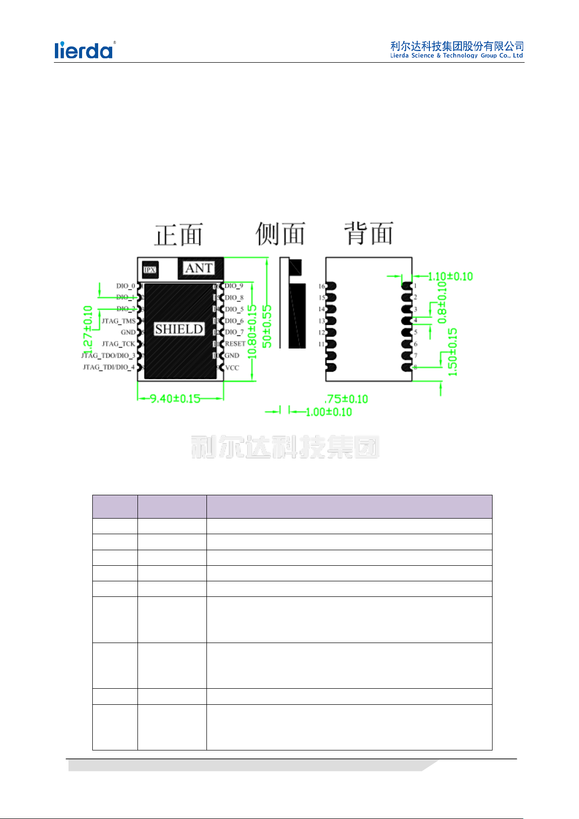
Chapter2 layout and interface
figure 2-1 module pin dimension
name function remark
VCC Power
GND
DIO_0 UART_RX1 UART 1 receive pin
DIO_1 UART_TX1 UART 1 transmit pin
DIO_2 UART_RX2 UART 2 receive pin
DIO_3 BRE
DIO_4 BTT
DIO_5 UART_TX2 UART 2 transmit pin
DIO_6 BT_CTL
1.8-3.6V,typical is 3.3V
Power Ground
Sleep state indication
0:Active state,module can receive UART data
1:Sleep state,module can’t receive UART data
Data receive indication
0:The data is sent to the MCU soon or now
1:at this time there is no data sent to the MCU
advertise control pin
Low:turn on BLE and be able to be discover
High:Close BLE stop to be discover or disconnected
table 2-1 pin description
Address: West Road, Hangzhou City, No. 1326 Leader Science Park
Page 4
page 4
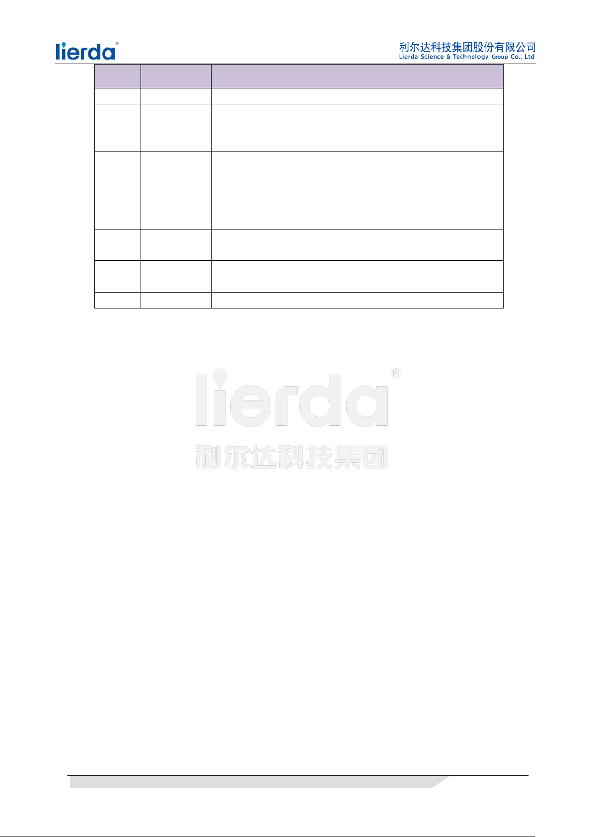
name function remark
DIO_7 MODE_CTL Must set to low
Sleep control pin
DIO_8 BRT
low:wake up module
high:permit module enter sleep module
Connection state indication:
0:The number of successfully connected slaves is below the
DIO_9 CONN
trigger condition
1:The number of successfully connected slaves meets or exceeds
the trigger condition
JTAG_
TMS
JTAG_
TCK
TMS
TCK
RESET Reset module
Address: West Road, Hangzhou City, No. 1326 Leader Science Park
Page 5
page 5
ead1
Chapter3 module control
3.1 UART communication
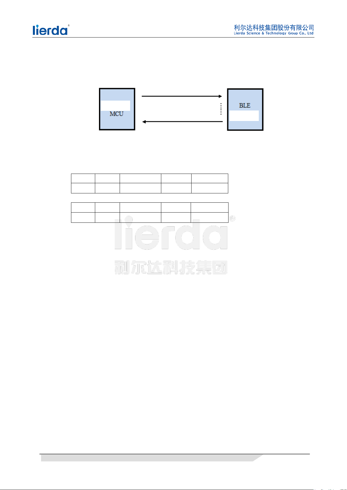
figure 3-1 communicaiton
3.1.1 UART frame structure
Input frame structure(hex):
Head1
01 FC xx xx xx……xx
Output frame structure(hex):
H
04 FC xx xx xx……xx
Head2 CommandID len content
Head2 CommandID len content
3.1.2 UART command ID
For the detailed description of serial commands, refer to "LSD4BT-S25A045905 command docoument"
3.2 Dual UART coexistence rules
Rule 1: from which serial port to establish a connection, the data related to the connection from which serial
port return
Rule 2: from which serial port to send commands, from which serial port to return
Rule 3: The above two rules can not be applied from the serial port 1 back (Automatic Connection exception)
Rule 4: When the module is automatically connected to the peripheral device, the first connected device is
bound to serial port 1, all subsequent connections are bound to port 2, and the binding is subject to rule 1.
Address: West Road, Hangzhou City, No. 1326 Leader Science Park
Page 6
page 6
3.3 other instructions
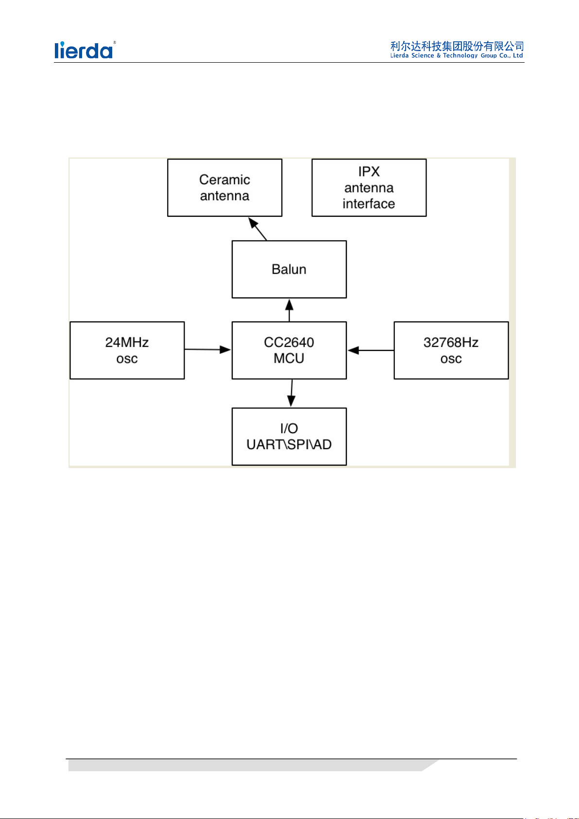
Block diagram
Chapter4 Notices
1. Please choose the right supply voltage
2. When using the module, pay attention to the correct pin order
Chapter5 To user
1, Thanks for using Lierda Technology Co., Ltd. products, before using our products,
please read this notice; If you have already started using instructions you have read and
accepted this notice.
2, Lierda reserves the right to interpret and modify all the information on this tool, if
any changes without notice.
Address: West Road, Hangzhou City, No. 1326 Leader Science Park
Page 7
page 7
Lierda Technology Group Co., Ltd.
IPG BT
2017-12
The device has been evaluated to meet general RF exposure requirement, The device can be used in
portable exposure condition without restriction.
This device complies with part 15 of the FCC rules. Operation is subject to the following two
conditions: (1) this device may not cause harmful interference, and (2) this device must accept
any interference received, including interference that may cause undesired operation.
NOTE: The manufacturer is not responsible for any radio or TV interference caused by
unauthorized modifications or changes to this equipment. Such modifications or changes
could void the user’s authority to operate the equipment.
This device complies with Industry Canada license-exempt RSS standard(s).
Operation is subject to the following two conditions:
(1) this device may not cause interference, and
(2) this device must accept any interference, including interference that may cause undesired operation
of the device.
Cet appareil est conforme avec Industrie Canada RSS exemptes de licence standard(s).
Son fonctionnement est soumis aux deux conditions suivantes:
(1) cet appareil ne peut pas provoquer d'interférences, et
(2) cet appareil doit accepter toute interférence, y compris celles pouvant causer un mauvais
fonctionnement de l'ap pareil.
A certified modular has the option to use a permanently affixed label, or an electronic label. For a
permanently affixed label, the module must be labelled with an FCC ID: N8NLSD4BTS25A and IC:
21461-LSD4BTS25A.
The OEM manual must provide clear instructions explaining to the OEM the labelling requirements,
options and OEM user manual instructions that are required
For a host using a this FCC certified modular with a standard fixed label, if (1) the module’s FCC ID
is notvisible when installed in the host, or (2) if the host is marketed so that end users do not have
straightforward commonly used methods for access to remove the module so that the FCC ID of the
module is visible; then an additional permanent label referring to the enclosed module:
“Contains Transmitter Module FCC ID: N8NLSD4BTS25A and IC:
“Contains FCC ID: N8NLSD4BTS25A and IC:
user manual must also contain clear instructions on how end users can find and/or access the module
and the FCC ID.
21461-LSD4BTS25A or
21461-LSD4BTS25A ” must be used. The host OEM
Address: West Road, Hangzhou City, No. 1326 Leader Science Park
Page 8
page 8
Host product is required to comply with all applicable FCC equipment authorizations regulations,
requirements and equipment functions not associated with the transmitter module portion.
compliance must be demonstrated to regulations for other transmitter components within the host
product; to requirements for unintentional radiators (Part 15B). To ensure compliance with all
non-transmitter functions the host manufacturer is responsible for ensuring compliance with the
module(s) installed and fully operational. If a host was previously authorized as an unintentional
radiator under the Declaration of Conformity procedure without a transmitter certified module and a
module is added, the host manufacturer is responsible for ensuring that the after the module is
installed and operational the host continues to be compliant with the Part 15B unintentional radiator
requirements. Since this may depend on the details of how the module is integrated with
the host, we suggest the host device to recertify part 15B to ensure complete compliance with FCC
requirement: Part 2 Subpart J Equipment Authorization Procedures , KDB784748 D01 v07, and KDB
997198 about importation of radio frequency device s into the United States.
Address: West Road, Hangzhou City, No. 1326 Leader Science Park
 Loading...