

Page 1
Installation instructions
Side-by-Side combinations
20190604
7088146 - 00
SBS(es/bs)
Page 2
General safety information
Contents
1 General safety information................................... 2
2 External dimensions of the appliance................. 2
3 Side-by-side assembly.......................................... 2
The manufacturer works constantly on the further development
of all the types and models. Therefore please understand that
we have to reserve the right to make design, equipment and
technical modifications.
To get to know all the benefits of your new appliance, please
read the information contained in these instructions carefully.
The instructions apply to several models. Differences may
occur. Text relating only to specific appliances is marked with
an asterisk (*).
Instructions for action are marked with a
action are marked with a .
, the results of
1 General safety information
-
The socket must be easily accessible so that
the appliance can be quickly disconnected
from the supply in an emergency. It must be
outside the area of the rear of the appliance.
DANGER identifies a situation involving direct
danger which, if not obviated, may
result in death or severe bodily
injury.
WARNING identifies a dangerous situation
which, if not obviated, may result in
death or severe bodily injury.
CAUTION identifies a dangerous situation
which, if not obviated, may result in
minor or medium bodily injury.
NOTICE identifies a dangerous situation
which, if not obviated, may result in
damage to property.
Note identifies useful information and tips.
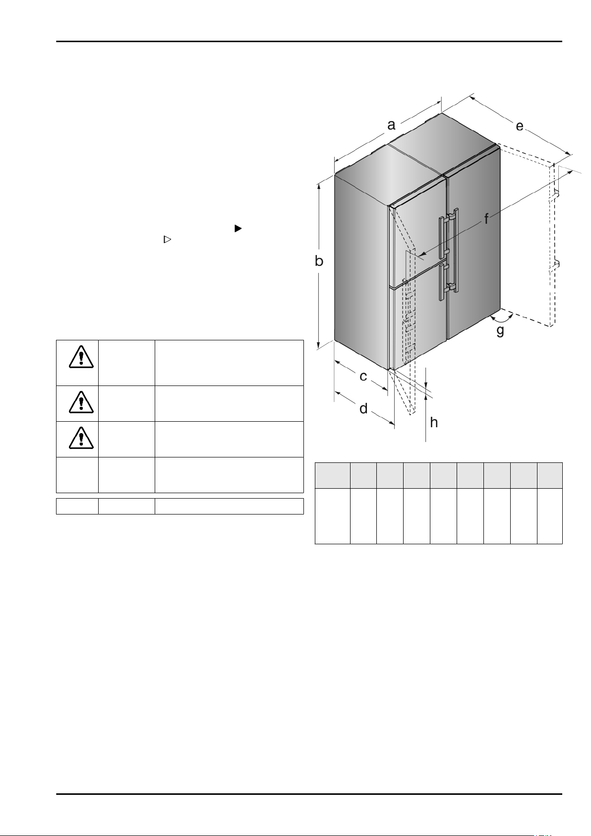
2 External dimensions of the
appliance
Fig. 1
Model a
[mm]b [mm]c [mm]d [mm]e [mm]f [mm]
SBS(e
s/bs)
86..,
SBSes
84..
x
If you are using wall spacers, add 15 mm to the dimensions.
With the door open, the dimensions apply to an opening angle
of 115 °. Distances vary depending on the opening angle.
1210 1850
600 x665
x
1185 x1752 115 35
g [°] h
[mm]
3 Side-by-side assembly
Install the freezer or the appliance with freezer compartment on
the left as viewed from the front. These appliances have a sidewall heating on the right-hand side to prevent the formation of
condensation.
All the assembly components are supplied with the appliance.
Fitting parts in the accessory kit.
2 * Depending on model and options
Page 3

Fig. 2
Fitting parts, supplied in the appliance.
Fig. 3
Side-by-side assembly
Tighten the outer adjustment feet. The appliances can be
u
moved easier
Push both appliances together up to approx. 10 mm apart so
u
that they stand flush at the front.
Line the appliances up with a spirit level on the top of the
u
appliance.
Top front of the appliance:
Fig. 5
Fig. 4
Ensure that the following tools are to hand:
SW 23/10 open-ended wrench (supplied)
q
Torx® 25/20/15 screwdriver
q
Power screwdriver
q
Spirit level
q
Information for moving the combined appliance:
Before assembling the appliances, site them as closely as
q
possible to the final position.
For proper assembly, the appliances must however be
accessible on all sides.
When moving the appliances after assembly, always grasp
q
the front outside corners. Never press your knee against the
side walls or door.
The combined appliance is easiest to shift diagonally by
q
moving the left and right corner alternately.
Once the combined appliance is exactly in front of the aperture, push it straight in.
If the combined appliance
q
has to be pulled out of the
aperture again, take hold of
it in the lower third area and
pull it straight forwards.
Fig. 6
Remove the existing covers.
u
Before fitting the top bracket remove both earthing screws
u
Fig. 6 (14)
Store the earthing screws safely. The screws are necessary
u
for fitting the bracket as shown below.
.
Fig. 7
Slide the bracket
u
between the appliances. Screw the brackets in loosely alternately right and left with four screws
ously removed earthing screws
If necessary, line the appliances up with a spirit level on the
u
top of the appliance.
Bottom front of the appliance:
Fig. 7 (3)
onto the pins with the spacer
Fig. 7 (4)
Fig. 7 (14)
and the previ-
.
NOTICE
Risk of damage when moving the combined SBS appliance!
The combined SBS appliance is heavy once assembled. The
appliance may be dented by improper movement.
Observe the information given on moving the appliance (see
u
above).
Remove all protective film from the outside of the housing.
u
Bottom front of the appliance:
* Depending on model and options 3
Page 4

Side-by-side assembly
Fig. 8
Remove the existing covers.
u
Slide the bracket
u
appliances and screw in loosely with the 4 screws
If necessary line the appliances up again.
u
Now tighten the screws firmly at the top and bottom.
u
Top back of the appliance:
Fig. 8 (6)
on with the spacer between the
Fig. 8 (4)
Slide the bracket
u
retainer for the wall spacers.
Mark the position of the holes to be drilled with a pencil.
u
Remove the bracket again.
u
.
Fig. 10 (8)
on with the slots over the
Fig. 11
NOTICE
Only drill through the metal plate. Drilling depth approx. 1mm.
Fig. 9
Slide the bracket
u
the lugs and with the spacer between the appliances. Screw
in firmly with the 2 screws
Bottom back of the appliance:
Fig. 9 (7)
onto the top of the appliance with
Fig. 9 (5)
.
Pre-drill the screw holes with a 3 mm drill and deburr.
u
Fig. 12
Slide the bracket
u
the retainer for the wall spacers.
Screw in tightly with the 2 screws
u
Before fitting the top and front cover strips, push the two bars
together over the whole length. The strips can be inserted more
easily into the gap. Use a soft cloth to push the strips in to avoid
dents in the surface of the cover strips. Press the strips into the
gap carefully and evenly in order to achieve an optimum bond.
Fig. 12 (8)
on once more with the slots over
Fig. 12 (5)
.
Fig. 10
NOTICE
Holes for the screws must be pre-drilled.
4 * Depending on model and options
Page 5

Fig. 13
On the top press the short cover strip
u
horizontal gap.
Fig. 13 (9)
Fig. 14
On the front, press the long trim
u
gap. Ensure that the strip rests on the connecting plate.
Peel the protective film off the cover strip.*
u
Fig. 14 (10)
into the vertical
into the
Side-by-side assembly
Connect the appliance to the fixed water connection
u
according to the manual.
NOTICE
Risk of damage when moving the combined SBS appliance!
The combined SBS appliance is heavy once assembled. The
appliance may be dented by improper movement.
Observe the information given on moving the appliance (see
u
above).
Carefully slide the combination into the intended position.
u
If necessary, align the height with the height-adjustable feet.
u
Then support the door: Lower the adjustment feet on the
u
mounting block until they rest on the floor then turn a further
90°.
The doors can be aligned in
height with the aid of the outer,
lower turn hinges:
Extend the threaded pin
u
Fig. 17 (17)
turn at most!).
a little (by one
Fig. 17
Fig. 15
Snap the top cover
u
between the two control panel trims. Make sure that the
outer sides of the cover form a flush finish with the control
panel trims
Fig. 15 (11)
onto the still open gap
Fig. 16
Place the bottom cover
u
the front (1), slide it down (2) and snap it in at the bottom (3).
To disassemble the cover, insert a screwdriver at the bottom
u
on the side below the cover and release both lower hooks.
The cover can swing out towards the top.
Connect the combination to the mains according to the
u
manual.
Appliances with IceMakers:
Fig. 16 (12)
onto the bracket from
Fig. 18
In order to lift the door unscrew the mounting block
u
Fig. 18 (18)
Fig. 18 (2)
screwed in.
Tighten the threaded pin
u
bearing pin.
clockwise with the supplied open-end wrench
. When delivered the mounting block is completely
Fig. 17 (17)
again to secure the
* Depending on model and options 5
Page 6

Liebherr-Hausgeräte Ochsenhausen GmbH
Memminger Straße 77-79
88416 Ochsenhausen
Deutschland
home.liebherr.com
 Loading...