

Page 1
Operating instructions
for upright refrigerators
GB
7082 218-03
K/SK/es ...0 0406
Page 2
10
K/SK/es..0
* Depending on model and options
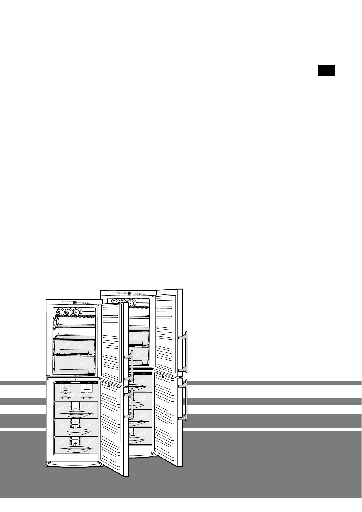
The appliance at a glance
Description of appliance and
equipment
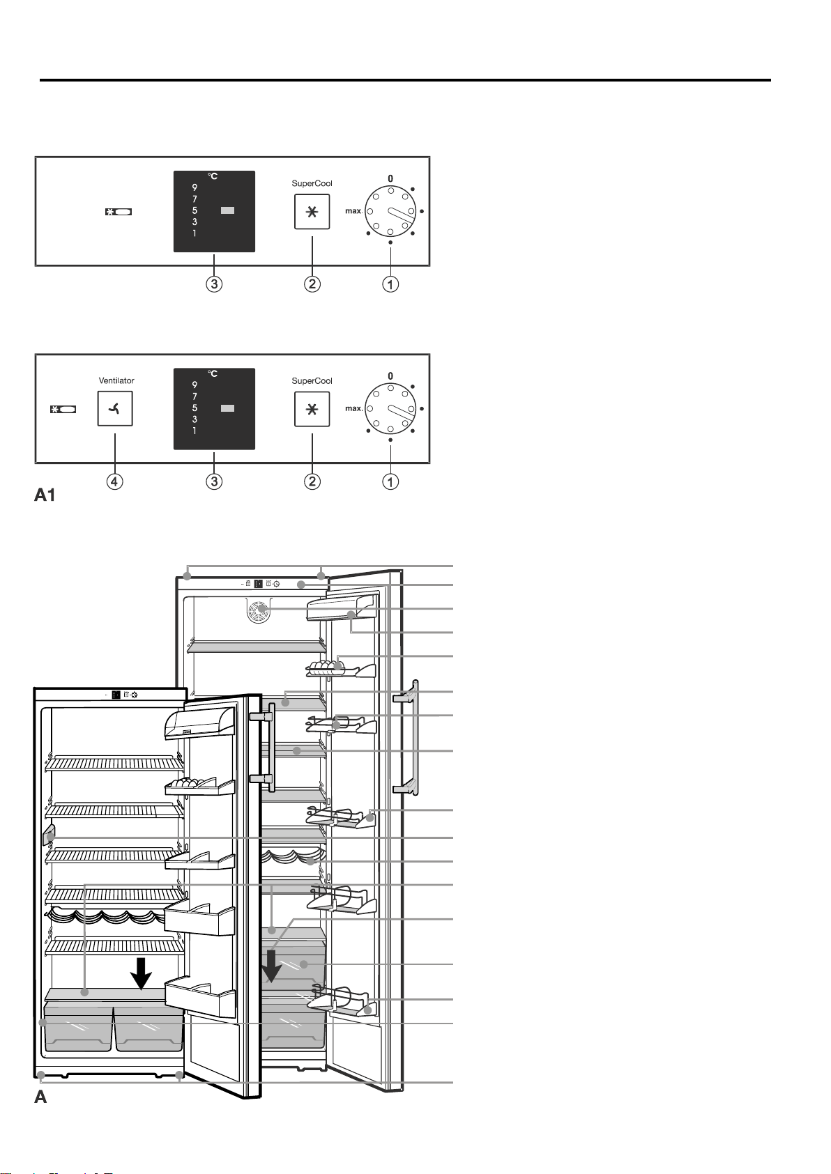
fig. A
Operating and control elements*
Adjustable bottle/can holder*
Sectioned shelves* or flap in grid shelf*
Door rack for large bottles and drinks
Vegetable, salad and fruit bins
Interior light
Type/Data plate -------->
Adjustable-height feet and transport grips
at front, transport castors at back
Adjustable-height jar rack
Egg tray*
Butter and cheese compartment
Fan for re-circulated air cooling*
Defrost drain
Bottle shelf*
Adjustable* storage shelves
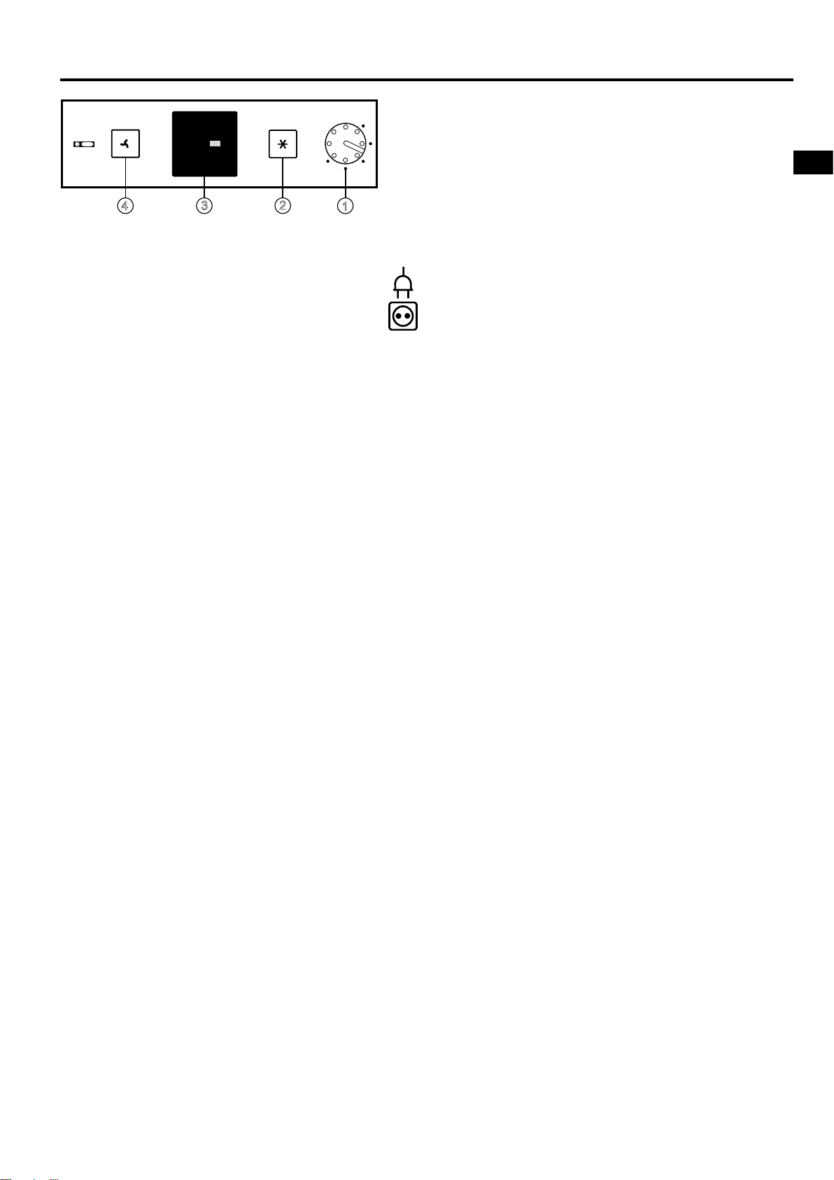
Operating and control
elements
fig. A1
1 On/off and temperature control
Setting 1 = warm
Setting "max." = cold
Recommended temperature setting: 5°C
2 SuperCooling button* for fast cooling of
food, lit = function activated
3 Temperature setting display
4 Fan on/off button* for re-circulated air cool-
ing - even temperature distribution throughout refrigerator, lit = function activated
Rear transport grips
Coldest area of the refrigerator compartment,
suita-ble for cold-sensitive and highly perishable foods
Page 3
11
K/SK/es..0
GB
Congratulations on your purchase. In choosing this appliance you have opted for all the benefits of stateof-the-art refrigeration technology, guaranteeing you top quality, a long life span and excellent reliability.
The features on your appliance have been designed to ensure maximum convenience - day in, day out.
This appliance has been manufactured with recyclable materials using an environmentally friendly process, so together you and we are making an active contribution to the preservation of our environment.
To get to know all the benefits of your new appliance, please read the information contained in these
operating instructions carefully.
We wish you much pleasure with your new appliance.
Keep these operating instructions in a safe place and
pass them on to the next owner, where applicable.
The operating instructions apply to several models. Differences may therefore occur.
Contents Page
Operating instructions
The appliance at a glance .................................. 10
Contents ............................................................ 11
Type/Data plate .................................................. 11
Safety regulations .............................................. 11
Energy savings ................................................... 11
Safety instructions and warnings ............................ 12
Disposal notes ................................................... 12
Setting up ........................................................... 12
Operation and control elements .............................. 13
Connecting to the mains .................................... 13
Switching the appliance on and off ................... 13
Setting the temperature ..................................... 13
SuperCooling ..................................................... 13
Temperature setting display ............................... 13
Fan switch .......................................................... 13
Storage, shelf arrangement, interior light ................ 14
Arranging food in the refrigerator ....................... 14
Changing shelf arrangement .............................. 14
Interior light ........................................................ 14
Defrosting, cleaning ................................................. 15
Troubleshooting ....................................................... 15
Customer service and type plate ....................... 15
Instructions for installation and modification
Dimensions ................................................. 16
Changing over door hinges ................................ 16
Insertion into row of kitchen units ...................... 16
Notes on assembling decor panels ................... 17
Safety regulations
W The appliance is intended for chilling food. It is de-signed
as a household appliance. If used commercially, the relevant regulations on commercial use must be observed.
W The appliance is set to operate within specific ambient
temperature limits according to its climate rating. These
temperature limits should not be exceeded. The correct
climate rating for your appliance is indicated on the type
plate. This is explained as follows:
Climate rating Set for ambient
temperatures of
SN +10°C to +32°C
N +16°C to +32°C
ST +18°C to +38°C
T +18°C to +43°C
- The refrigerant circuit has been tested for leaks.
- The appliance complies with current safety regulations
and EC directives 73/23/EEC and 89/336/EEC.
Notes on energy saving
W Ensure that there is adequate space around the appli-
ance for ventilation and air extraction.
W Avoid keeping the door open for too long.
W Store food logically. Do not exceed the storage period
specified.
W Keep all food properly packed and covered so as to avoid
condensation.
W Always allow hot food to cool to room temperature before
placing in the appliance.
W Defrost frozen food in the refrigerator.
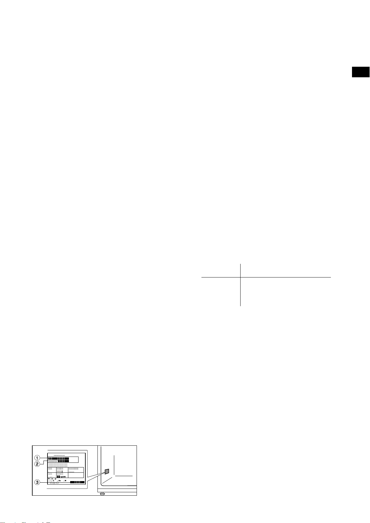
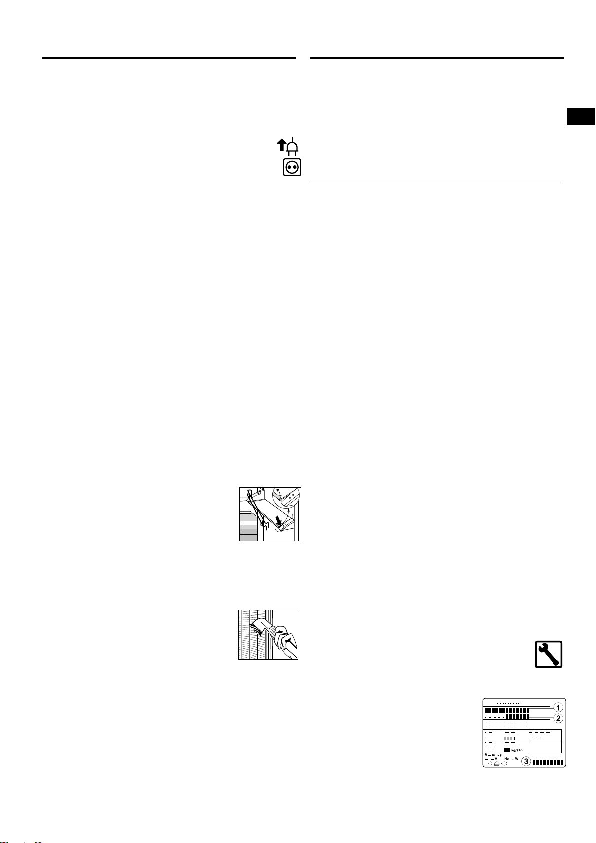
Type/Data plate
1 Type designation
2 Service number
3 Appliance number
!
§
Page 4
12
K/SK/es..0
Safety instructions and warnings
Disposal notes
The packaging is designed to protect the appliance
and individual components during transport and is
made of recyclable materials.
- Corrugated board/board
- Moulded polystyrene (foamed, CFC-free polystyrene)
- Polythene bags and sheets
- Polypropylene straps
W Keep packaging materials away from children - poly-
thene sheets and bags can suffocate!
W Please return the packaging material to your nearest of-
ficial collection point so that the various materials can be
reused or recycled as far as possible.
Your old appliance:
This contains some reusable materials and should
be disposed of properly - not simply with unsorted
household refuse.
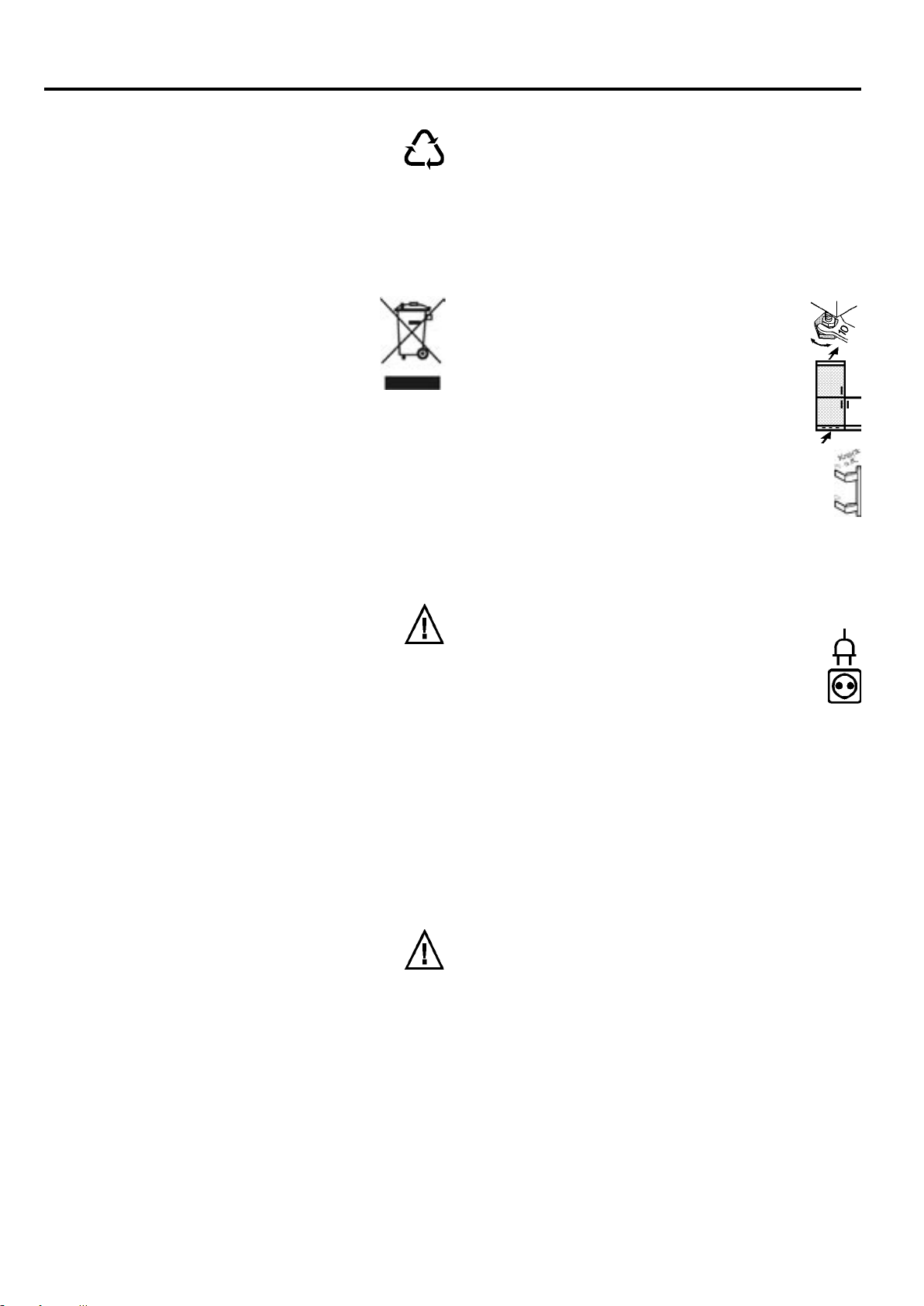
W Disable discarded appliances immediately by re-
moving the plug and cutting through the connection cable.
W Remove the spring-action or bolt catch from the
appliance so that playing children cannot become
trapped inside and suffocate.
W Make sure that the refrigerant circuit of an appliance that is
no longer needed is not damaged before it is collected or
handed in at a municipal collection point so as to ensure that
the refrigerant or oil does not escape into the environment.
- Exact details of the refrigerant used can be found on the
type plate. The heat insulator is PU with Pentane.
- Information on collection dates or collection points can
be obtained from the waste disposal authorities or your
local council.
Technical safety
W To prevent injury or damage to the unit, the appli-
ance should only be transported wrapped and set
up by two people.
W The refrigerant R 600a is environmentally friendly but
flammable.
W Do not damage the refrigerant circuit pipes. Splashes of
refrigerant can harm your eyes or ignite.
W If refrigerant escapes, remove all naked flames or
sources of ignition in the vicinity of the leak, disconnect
the appliance from the mains and ventilate the area well.
W In the event that the appliance is damaged, contact the
supplier immediately before connecting to the mains.
W To guarantee safe operation, ensure that the appliance is set up
and connected as described in these operating instructions.
W Disconnect the appliance from the mains if any fault
occurs. Pull out the plug (not by pulling on the mains
cable) or switch off or remove the fuse.
W
Any repairs and work on the appliance should only be
carried out by the customer service department, as
unauthorised work could prove highly dangerous for
the user. The same applies to changing the mains power
cable.
Safety during use
W Do not store explosives or sprays using combus-
tible propellants such as butane, propane, pentane, etc. in the appliance. Electrical components
might cause leaking gas to ignite. You can identify such
sprays by the printed contents or a flame symbol.
W Only store high-percentage alcohol in tightly sealed,
upright containers.
W Do not allow naked flames or ignition sources to enter
the appliance.
W Do not use electrical appliances inside the appliance
(e.g. steam cleaners, heaters, ice makers, etc.).
W Do not stand on the plinth, drawers or doors or use
them to support anything else.
W This appliance is not intended for use by persons (in-
cluding children) with reduced physical, sensory or
mental capabilities or lack of experience and knowledge
unless they have been given initial supervision or instruction concerning use of the appliance by a person
responsible for their safety. Children should be supervised to ensure that they do not play with the appliance.
W Avoid prolonged skin contact with cold surfaces or
chilled/frozen food. This could cause pain, numbness
and frostbite. In the case of prolonged skin contact,
protective measures should be taken, e.g. gloves should
be worn.
W Do not consume food which has been stored for too
long, as it could cause food poisoning.
Setting up
W When setting up/fitting ensure that the refrigerant circuit
pipes are not damaged.
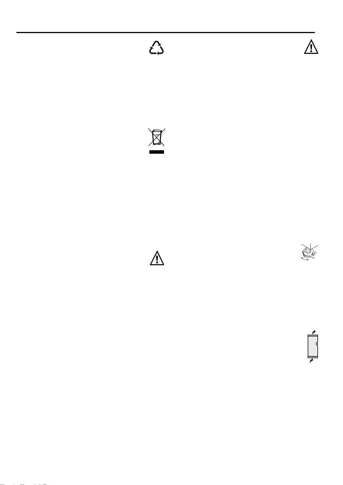
W Once in position, use the 10 spanner provided to
adjust the feet so that the appliance is level and
does not wobble.
W Avoid positioning in direct sunlight or next to an
oven, radiator or similar, in damp locations or near spraying water.
W Standard EN 378 specifies that the room in which you
install your appliance must have a volume of 1 m3 per 8
g of R 600a refrigerant used in the appliance, so as to
avoid the formation of inflammable gas/air mixtures in
the room where the appliance is located in the event of a
leak in the refrigerant circuit. The quantity of refrigerant
used in your appliance is indicated on the type plate on
the inside of the appliance.
W The ventilation grilles should not be obstructed.
Always ensure that there is good ventilation and
that the outward flowing air is able to escape.
Please note the appendix concerning installation
instructions.
W Do not place heat-emitting appliances, e.g. micro-
wave oven, toaster, etc., on top of the refrigerator or
freezer.
W Remove all transportation safety components.
Page 5
13
K/SK/es..0
GB
Operation and control elements
Setting the temperature
W Turn the temperature control 1 with a coin until the
desired temperature is indicated in the display. The slot
positions mean:
Setting 1 = highest temperature,
lowest cooling setting
Setting "max." = lowest temperature,
highest cooling setting
W Recommended temperature setting: 5°C.
Please note that the temperature inside your appliance will
depend on where you have put it, the temperature in the
room, how often you open the door, and what you put in it.
If necessary, re-adjust the temperature control.
Temperature setting display
- When the temperature display 3 is illuminated, this indi-
cates that the appliance is running.
- The five blocks in the display each relate to a different
temperature range. They indicate the refrigerator tem-
perature setting you have selected.
- Within the temperature / setting range, e.g. when the dis-
play reads 5 °C to 7 °C, or between two settings*, the tem-
perature can be set slightly colder. If required, slowly turn
the tempera-ture control 1 further - the light displaying
the temperature range, e.g. 5 °C, flashes for a short time.
This confirms the colder setting within the small tempera-
ture range.
SuperCooling*
The SuperCooling button 2 switches the appliance to
maximum cooling. This will enable you to achieve temporarily lower refrigerating temperatures.
It is recommended particularly if you wish to cool large
quantities of food, drinks, freshly baked cakes or meals
rapidly
W To switch on: Press the SuperCooling button 2 briefly
so that it lights up.
- The refrigerator temperature will drop to its lowest value.
W To switch off: Press the SuperCooling button again so
that it goes dark.
NB:
- The SuperCooling function uses slightly more energy.
After approx. 6 hours, however, the appliance switches
back automatically to normal energy-saving operation.
Fan switch*
for re-circulated air cooling 4:
You can use the fan switch as required to:
- chill large quantities of fresh food fast;
- keep the temperature evenly distributed throughout the
entire refrigerator compartment. The air will circulate
more intensively, thus keeping all the different areas in the
appliance at the same temperature and ensuring that all
the food inside is chilled at the same temperature.
W You are recommended to always use the fan switch:
- in high room temperatures (approx. 30°C or higher) or
- if the air humidity is high, e.g. during the summer.
W To switch on: Press the fan button 4 briefly so that it
lights up.
W To switch off: Press the fan button again so that it goes dark.
NB:
- To save energy, the fan will switch off automatically when
the door is open.
You are advised to clean the appliance before switching it
on for the first time (see "Cleaning").
Connecting to the mains
Power supply (AC) and voltage
at the operating point must comply with the details on
the type plate, which is located inside the appliance on the
left, fig. A.
W Connect the appliance with a properly earthed fused
plug and socket only.
W The socket must be fused with a 10 A fuse or higher, it
must be away from the rear of the appliance and must be
easily accessible.
W Do not
- connect to stand-alone inverters,
- operate with so-called energy-saving plugs - this can
damage the electronic system,
- connect to the supply with other equipment using an
extension cable - risk of overheating.
W When removing the mains cable from the back of the ap-
pliance, remove the cable holder as well so as to avoid
vibration noise.
The wires in the mains lead are coloured in accordance with
the following code: green/yellow = earth, blue = neutral,
brown = live.
Warning! This appliance must be earthed.
Non-rewireable plugs BS 1363
If this machine or appliance is fitted with a non-rewireable
plug, the following information applies: If the socket outlets
are not suitable for the plug supplied with this product, it
must be cut off and an appropriate plug fitted. The plug cut
from the flexible cord should be disposed of and on no account be inserted into a 13 A socket elsewhere in the house
(electric shock hazard).
The fuse cover must be re-fitted when changing the fuse,
and if the fuse cover is lost the plug must not be used until
a suitable replacement is obtained. The colour of the correct replacement cover is that of the coloured insert in the
base of the plug, or the colour that is embossed in words on
the base of the plug (as applicable to the design
of the plug
fitted). The correct rating of the replace
ment fuses that are
ASTA approved to BS 1362 should be fitted. Replacement
fuse covers may be purchased from your local electrical
suppliers, electricity showroom or approved service agent.
Switching the appliance on and off
fig. A1
W To switch on: Turn the temperature control 1 with a coin
so that the slot is pointing to setting 2.
- A green light on the temperature display will light up and
indicate that the appliance is in normal mode.
- The interior light will switch on.
W To switch off: Set the temperature control to "0".
- The temperature display and all buttons will go out.
- The interior light will go out.
* Depending on model and options
max.
0
2
3
4
A1
Ventilator
SuperCool
1
°C
9
7
5
3
1
Page 6
14
K/SK/es..0
Storage, shelf arrangement, interior light
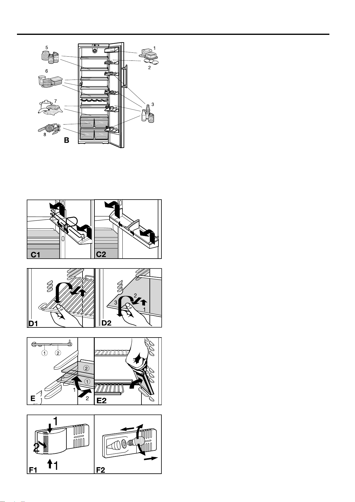
Arranging food in the refrigerator
The natural circulation of the air inside the refrigerator
results in different parts of the refrigerator having different
temperatures. This can have its advantages for different
types of food. The refrigerator is coldest just above the vegetable bins and against the rear wall (suitable for sau-sage
and meat products etc.); it is warmest at the front at the top
and in the door (suitable for spreadable butter, cheese etc.).
See fig. B for food storage suggestions.
Notes on cooling
- Store food so that air can circulate properly around it.
Do not pack the refrigerator too full. Do not cover the fan
slits* at the back, otherwise the refrigerating capacity will
be impaired!
- Food which gives off or absorbs odours and flavours,
and liquids should always be stored covered or in closed
containers.
- Always store food which gives off or is sensitive to ethylene gases such as fruit, vegetables and salads separately
or wrapped in order not to affect their storage life; e.g. do
not store tomatoes together with kiwis or cabbage.
Changing shelf arrangement
You can re-arrange the height of the shelves and door racks
as required.
W Re-positioning the door racks, fig. C: Slide the door
rack up, pull out towards you and replace in reverse
order.
W By adjusting the bottle holder you can protect the
bottles from falling over when the door is opened and
closed. Always hold by the plastic handle.
W Re-positioning the shelves, fig. D:
- Lift the shelf, slide forwards and remove.
Always insert shelves with the guard bar at the back
pointing upwards, otherwise food may freeze onto the
rear wall.
- The glass shelves are fitted with stops to prevent them
being pulled out accidentally.
W If you require space for large bottles and containers,
- lift the front half of the split glass shelf* and carefully
slide it under the back half until the stops* click into the
recesses, fig. E1, or
- lift up the flap* in the grid shelf, fig. E2.
Interior light
This switches off automatically after the door has been
opened for approx. 15 minutes. If it does not switch on
when the door is opened briefly, but the temperature setting
display is working, the bulb may be defective.
Changing the bulb:
W Bulb data: max. 25 W, voltage and current should agree
with the details on the type plate. Only use bulbs of the
same size. Bulb fitting: E 14.
W Switch off the appliance.
Pull out the plug or switch off/unscrew the fuse.
W Fig. F1: Press the light cover together at the sides (1), lift
out and unclip (2).
W Fig. F2: Replace the bulb. To counteract the friction of
the lock washer, turn the bulb with slightly more pressure.
When inserting the new bulb, ensure that the lock washer
is properly in place in the lamp socket.
W Clip the back end of the cover in and clip the sides into
place.
* Depending on model and options
6 dairy products
7 meat and sausage
products, fish, pre-cooked
meals
8 fruit, vegetables, salad
1 butter, cheese
2 eggs
3 cans, drinks, bottles
5 preserves, baked goods
Page 7
15
K/SK/es..0
GB
Defrosting, cleaning
Defrosting
The refrigerator compartment defrosts automatically. The
defrost water is evaporated by the heat from the compressor; drops of water on the rear wall are perfectly normal.
W Ensure that the defrost water can flow freely through the
drain hole in the rear wall (arrow in fig. A).
Cleaning
W Before cleaning, always switch off the appliance.
Disconnect from the mains or unscrew or switch
off the fuse.
W Clean the outer walls, inside and equipment by hand with
lukewarm water and a little detergent. Because of the
risk of injury and damage to the appliance, steam cleaning equipment should not be used.
W We recommend using a soft cloth and an all-purpose
cleaner with a neutral pH value. Only use food compatible
cleaning and care agents on the inside of the appliance.
W
Use a commercially available stainless-steel cleaning
agent for stainless-steel appliances*.
- In order to achieve best possible protection, apply a stainless-steel care agent uniformly in grinding direction after
cleaning. Points which are darker at the start and a more
intensive coloration of the stainless-steel surface are normal.
- Do not use abrasive sponges or scourers, do not use concentrated cleaning agents and never use cleaning agents
containing sand, chloride or acid or chemical solvents, as
these would damage the surfaces and could cause corro-
sion.
W Ensure that no cleaning water penetrates into the ventila-
tion grille or any electrical components, and keep it out of
the defrost drain as far as possible. Wipe the appliance
dry.
- Do not damage or remove the type plate on the inside of
the appliance. It is very important for servicing purposes.
W The butter dish* can be washed in a dishwasher. The
racks, shelves and other components should be cleaned
by hand as they are not dishwasher-safe.
- The shelves and door racks can be dismantled for cleaning. Remove the trims
and sides from the glass shelves. Remove
the protective film from the decorative
trims.
W Clean the drain hole on the rear wall frequently, fig. A,
arrow. If necessary, clean with a thin object, e.g. a
cotton swab or similar.
W The dust should be removed from the
refrigeration unit and heat exchanger
- metal grid at the back of the appliance
- once a year.
Dust deposits increase energy consump-
tion.
W Ensure that none of the wires or other components are
dislodged, bent or damaged.
W Then connect/switch on the appliance.
If the appliance is to be left switched off for any length
of time, empty the appliance, disconnect from the mains,
clean as described above and leave the door open so as to
avoid odours.
Appliance does not work
- Is the appliance switched on properly?
- Is the mains plug properly inserted in the socket?
- Is the socket fuse intact?
The interior light does not come on
- Is the appliance switched on?
- The bulb is defective. Change the bulb as described in
"Interior light".
Loud running noise
- Is the appliance standing firmly on the floor, or does the
compressor cause nearby items of furniture or objects
to vibrate?
If necessary, move bottles and containers apart.
- Burbling noises are normal. These are caused by the
refrigerant flowing round the refrigerant circuit.
A short clicking sound: This will be heard whenever the
refrigeration unit (the motor) switches on or off automatically.
Motor noise: This will be slightly louder for a brief period
when the refrigeration unit switches on.
A low-pitched humming sound is caused by air flow
noises in the fan.
The temperature is not cold enough
- Is the temperature setting correct?
If necessary, set a lower temperature.
- Loose thermometer in appliance is showing a wrong
reading.
- Does the door close properly?
- Is the appliance sufficiently well ventilated?
Clear ventilation grilles if necessary.
- Is the ambient temperature too hot?
(See "Safety regulations")
- Has the appliance been opened too often or left open
too long?
Your appliance is designed and manufactured for a long
life span and reliable operation.
If a malfunction nonetheless occurs during operation,
check whether it is due to an operating error. Please note
that even during the warranty period the resultant servicing
costs in this case will have to be borne by the owner.
You may be able to rectify the following faults by checking
the possible causes yourself:
Malfunction Possible cause and remedy
Customer service and type plate
If none of the above causes apply and you cannot
rectify the fault yourself, please contact your nearest
customer service department (see enclosed list for addresses). State the:
type designation 1,
service number 2and
appliance number 3
as given on the type plate so as to
ensure rapid, accurate servic-ing. The
type plate is located inside the appliance on the left-hand side.
Troubleshooting
* Depending on model and options
Page 8

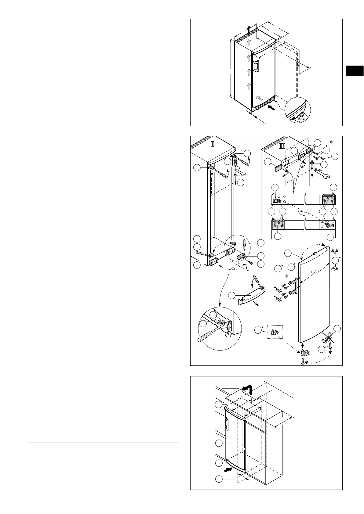
Instructions for installation and modification
Dimensions
The external dimensions of the appliance can be seen on
the illustration on the opposite page (fig. S) and in the table
below.
Gross capacity External dimensions [mm]
of appliance [l] A B C D E F
(see type plate)
_____________________________________________________
258 (26..) 1250 600 631 614 644 1179
309 (31..) 1447 600 631 614 644 1179
362 (36..) 1644 600 631 614 644 1179
413 (42..) 1841 600 631 614 644 1179
_____________________________________________________
362 (36..) 1644 660 683 662 704 1287
413 (42..) 1841 660 683 662 704 1287
Installation instructions
- Do not install the appliance directly next to another refrigerator or freezer. This is important to prevent condensation and consequential damage resulting from it.
- This does not apply to Side-by-Side models (SBS). They
are designed for Side-by-Side installation with another
refrigerator/freezer.
The "Installation instructions for Side-by-Side combina-
tions" are supplied in the accessories bag for the SBS
freezer or the appliance with a freezer compartment.
Changing over door hinges
On appliances which are intended for individual installation
the door hinges can be changed from one side to the other.
On SBS appliances in stainless steel finish, which are designed for Side-by-Side installation, the door hinges must
not be transferred to the other side!
W Only change over door hinges when mains plug is dis-
connected!
W Fig. T. With the door open, lever out plinth panel 1 on
the hinge side with a screwdriver and remove from front.
- Lever out cover 2 with a screwdriver.
Close door.
- Unscrew screw M5 3.
W Pull hinge component 4 with hinge pin 5 out from un-
derneath and remove.
W Open door, lift out at bottom and remove; do not lose the
spacer bl.
W Transfer all hinge components onto the other side:
W Top: depending on version, proceed as follows:
Version I (visible operating panel): Lever out covers 8
with a screwdriver at the front and remove at an angle
from below. Remove hinge pin 7 and insert on the opposite side. Use the hexagon socket on the open-ended
spanner provided (spanner width 5). Fit covers 8 again:
insert at rear and click into place at front.
Version II (concealed operating panel): Lift up cover 8
on handle side, push outwards; lift up cover on hinge side
and pull off.
- Unscrew earthing plate cm: first earthing screw cl, then
inner retaining screw cq.
- Unscrew hinge 9: first undo earthing screw cl, then retaining screws cq. Fit hinge 9 to opposite side: for easy
assembly, fit hinge from above and first tighten with the
upper retaining screw cq M5, then screw cq and finally
earthing screw cl M4.
- Turn earthing plate cm through 180° and screw tight again
on the new handle side: first retaining screw cq, then
earthing screw cl.
- Insert hinge pin 7 in the other retaining hole. Use the
hexagon socket on the open-ended spanner provided
(spanner width 5).
- Fit covers 8 again: insert hinge-side cover by sliding
outwards and click into position; insert handle-side cover
by sliding inwards and click into position.
- Bottom: Using a screwdriver, remove the spacer bo and
replace on the other side, fig. T1.
W Re-attach the door:
- Remove plugs bp from the door mounting points and
replace on the other side.
- Only on 1644 mm and 1841 mm high stainless-steel ap-
pliances: Unscrew the closure dl underneath the door on
the hinge side. Fit the closure provided separately dm on
the new hinge side and screw into place with the
same screw dn. Discard the old closure dl (or keep
it for later use).
- Suspend door with spacer in hinge pin 7, close door.
- Rotate hinge component 4 by 180°, remove hinge pin 5,
turn by 180° and replace. Mount both parts in the hinge bq:
slide the pin into the door mounting through the hinge, tilt in
the hinge component, slide up and attach with screw 3.
W Align the door flush with the body of the appliance using
the slot on the hinge bq, then tighten screw 3.
W Attach the plinth panel 1 and click into place by pressing.
W With the door open, insert the cover 2 in the plinth panel
at the front and click into place at the back.
W Transfer* door handle br and plugs bt. With the door
open, carefully lift out the pressure plates* bs at the front
and slide away; unscrew handle.
Reassemble in reverse order: replace the pressure plates
and click into position.
16
* Depending on model and options
K/SK/es..0
Page 9
T
SW5
*
SW5
180°
1
2
3
4
5
7
9
9
8
1
2
3
4
8
8
8
13
15
I
II
20
20
21
21
10
T1
15
13
7
25
25
580
631
614
min. 50
ca. 36
min.
300 cm
2
[mm]
U
A
B
E
F
56,5
C
D
[mm]
S
10
14
*
18
*
31
*
16
*
17
Torx 15
9
25
20
Torx 25
30
32
Insertion into row of kitchen units
Fig. U. 600 mm appliances can be installed in a row of
kitchen units. To adapt the height of the appliance to the
surrounding furniture a top unit 1 can be added.
A gap of at least 50 mm depth must be provided behind and
along the entire width of this unit so as to ensure sufficient
ventilation. The area of ventilation underneath the ceiling
should be at least 300 cm2. The greater the area the more
economically the appliance will run.
W When installing with standard kitchen units (max. depth
580 mm) and decor panels of max. 2 mm thickness, the
appliance can be set up right next to the kitchen unit.
The door protrudes 34 mm from the side of the kitchen
unit and 51 mm at the front. This enables it to be opened
and closed without difficulty.
W When setting up the appliance next to a wall 4, a mini-
mum distance of 36 mm must be provided on the hinge
side between the appliance and the wall (for the handle
when the door is open).
1 top unit 3 kitchen unit side panel
2 refrigerator/freezer 4 wall
GB
Notes on assembling decor panels*
600 mm wide and 1841 mm high appliances can be
matched or contrasted with your existing kitchen colour
scheme by attaching a decor panel and frames.
The panels are available from your kitchen furniture supplier.
The frames can be fitted later and are available from your
dealer.
If you wish to fit the decor panel yourself, you require a drill
or cordless screwdriver to pre-drill the retaining holes. The
door handles are to be replaced by the rigid handles included in the decor frame retrofit set.
For further instructions and dimensions see the installation
instructions included in the retrofit kit.
All types and models are subject to continuous improvement
and the manufacturer therefore reserves the right to make
modifications in the shape, equipment and technology.
K/SK/es..0
17
Page 10
BioCool
BioCoolBioCool
Operating instructions
for BioFresh NoFrost combined refrigerator-freezers
GB
7082 344-00
BN/BNes 2956/66 1105
Page 11
The appliance at a glance
BioCool
BioCool
A2
A
A1
BioCool
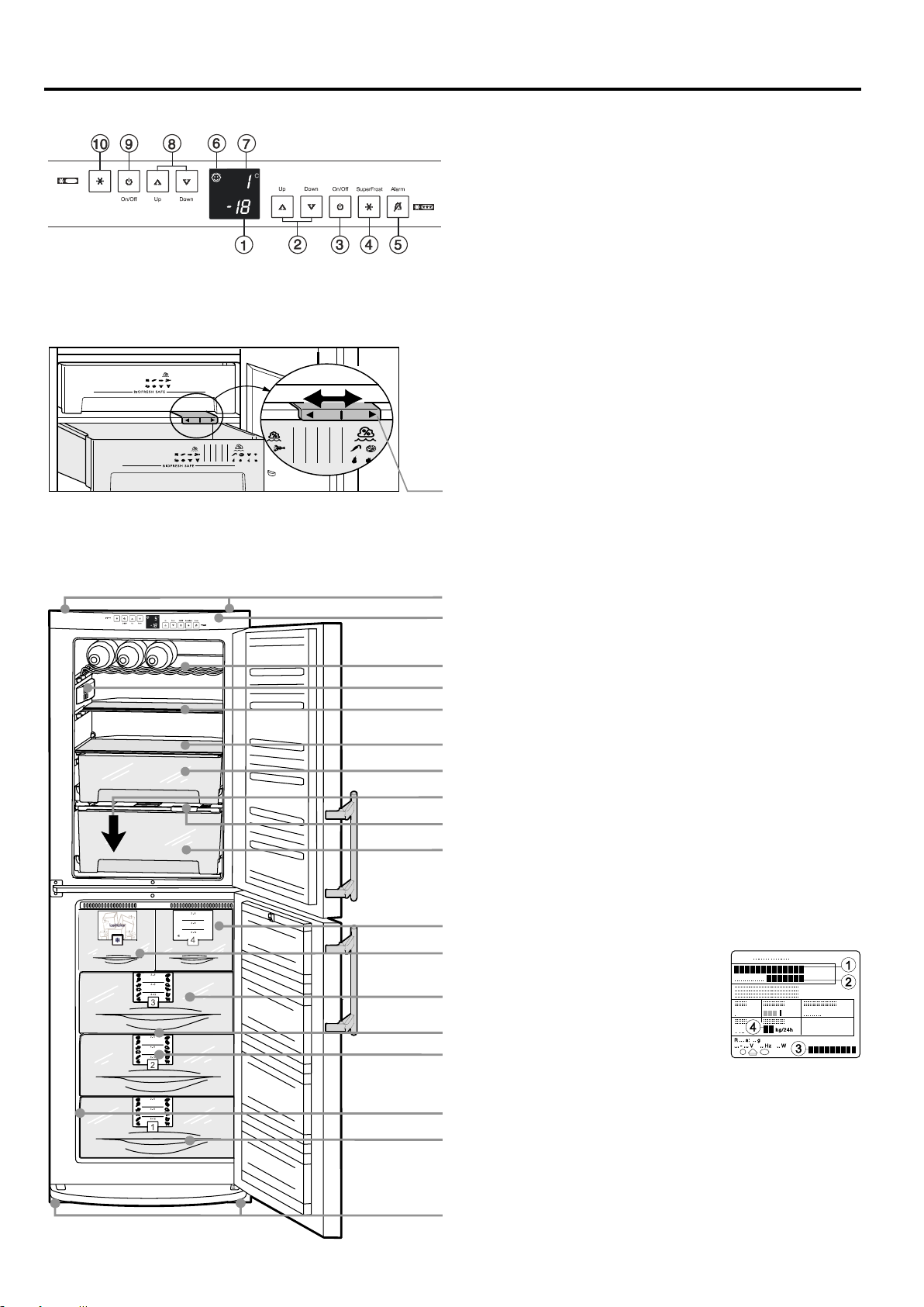
Operating and control elements, fig. A1
Freezer compartment
1 Temperature display and setting display with nA
FrostControl and power failure display with call-up function
for highest temperature
2 Temperature setting buttons: Up button = higher, Down =
lower, recommended setting: -18°C
3 On/off button
4 SuperFrost button, lit = function activated.
For fast freezing of fresh food
5 Audible warning on/off button
6 Child-proof lock (illuminated symbol = active, BioFresh and
freezer compartments are protected against being switched
off accidentally)
BioFresh compartment
7 Temperature display and setting display
8 Temperature setting buttons: Up button = higher, Down =
lower, recommended setting: 1°C
9 On/off button
bl BioCool button, lit = function activated.
For fast cooling of food in the BioFresh compartment
Humidity setting in BioFresh drawer, fig. A2:
slider to left: dry, slider to right: humid
Description of appliance and equipment
fig. A
Rear transport grips
Operating and control elements
BioFresh compartment, 0°C to 2°C
Champagne shelf for standard and small sparkling wine bottles
Interior light
Sectioned shelf
Zone with relatively dry climate
Drawer for dry and wrapped food
Defrost water drain
Humidity control
Drawer with adjustable humidity for storing salad,
vegetables and fruit in a humid climate
Freezer, approx. -18°C
Drawers with transparent front panel
IceMaker*
Freezer tray*, cold-storage accumulator*
Shelves and drawers can be removed to
make space for large items - VarioSpace
12
Information system*
A3
1 Type designation
Type/Data plate, fig. A3
Ice-cube tray*
Adjustable-height feet, front transport grips, transport castors
at back
* Depending on model and options
2 Service number
3 Appliance number
4 Freezing capacity
in kg/24 hours
BN/BNes...6
Page 12

Congratulations on your purchase. In choosing this appliance you have opted for all the benefits of state-of-the-art refrigeration technology, guaranteeing you top quality, a long life span and excellent reliability.
The features on your appliance have been designed to ensure maximum convenience - day in, day out.
This appliance has been manufactured with recyclable materials using an environmentally friendly process, so together you
and we are making an active contribution to the preservation of our environment.
To get to know all the benefits of your new appliance, please read the information contained in these operating instructions
carefully.
We wish you much pleasure with your new appliance.
Keep these operating instructions in a safe place and
pass them on to the next owner, where applicable.
The operating instructions apply to several models.
Differences may therefore occur.
GB
Contents
Operating instructions Page
The appliance at a glance ................................................. 12
Contents ....................................................................... 13
Safety regulations ......................................................... 13
Energy savings .............................................................. 13
Safety instructions and warnings ....................................... 14
Disposal notes .............................................................. 14
Setting up ...................................................................... 14
Connecting to the mains ............................................... 14
Operation and control elements ......................................... 15
Switching the appliance on and off .............................. 15
Setting the temperature ................................................ 15
Temperature display ...................................................... 15
Audible warning signal .................................................. 15
BioCool .........................................................................16
SuperFrost ...................................................................16
Power failure/FrostControl display ................................16
Additional functions ...................................................... 16
Child-proof lock ......................................................... 16
Display brightness ..................................................... 16
Interior light ................................................................... 16
BioFresh compartment ....................................................... 17
Freezer compartment .................................................... 18-19
Freezing with SuperFrost ............................................. 18
Notes on freezing and storage ..................................... 18
Information system ....................................................... 18
Freezer tray ................................................................... 19
Cold-storage accumulators .......................................... 19
Making ice-cubes ......................................................... 19
Cleaning ............................................................................. 19
Troubleshooting .................................................................. 20
Customer service and type plate .................................. 20
Instructions for installation and modification
External dimensions ...................................................... 20
Changing over door hinges ......................................20-21
Insertion into row of kitchen units ................................. 21
Safety regulations
W The appliance is designed to cool, freeze and store food
and to make ice. It is designed as a household appliance.
We cannot guarantee that the appliance will work properly
if it is used for another purpose.
W The appliance is set to operate within specific ambient
temperature limits according to its climate rating. These
temperature limits should not be exceeded. The correct
climate rating for your appliance is indicated on the type
plate. This is explained as follows:
Climate rating Set for ambient
temperatures of
SN +10°C to +32°C
N +16°C to +32°C
ST +18°C to +38°C
T +18°C to +43°C
- The refrigerant circuit has been tested for leaks.
- The appliance complies with current safety regulations
and EC directives 73/23/EEC and 89/336/EEC.
Notes on energy saving
W Ensure that there is adequate space around the appliance
for ventilation and air extraction.
W Avoid keeping the door open for too long.
W Store food logically. Do not exceed the storage period
specified.
W Keep all food properly packed and covered so as to avoid
its frosting up on the outside.
W Always allow hot food to cool to room temperature before
placing in the appliance.
W Defrost frozen food in the BioFresh compartment.
W Keep the appliance door shut in the event of a breakdown.
This will delay the cold loss and will help to maintain the
quality of the frozen food for longer.
§
!
BN/BNes...6
13
Page 13
Safety instructions and warnings
Disposal notes
The packaging is designed to protect the appliance
and individual components during transport and is
made of recyclable materials.
- Corrugated board/board
- Moulded polystyrene (foamed, CFC-free polystyrene)
- Polythene bags and sheets
- Polypropylene straps
W Keep packaging materials away from children - poly-
thene sheets and bags can suffocate!
W Please return the packaging material to your nearest
official collection point so that the various materials can be
reused or recycled as far as possible.
Your old appliance:
This contains some reusable materials and
should be disposed of properly - not simply with
unsorted household refuse.
W Disable discarded appliances immediately
by removing the plug and cutting through the
connection cable.
Remove spring-action or bolt catch from
the
appliance so that playing children cannot become
trapped inside and suffocate.
W Make sure that the refrigerant circuit of an appliance that
is no longer needed is not damaged before it is collec-
ted or handed in at a municipal collection point so as to
ensure that the refrigerant or oil does not escape into the
environment.
- Exact details of the refrigerant used can be found on the
type plate. The heat insulator is PU with Pentane.
- Information on collection dates or collection points can be
obtained from the waste disposal authorities or your local
council.
Technical safety
W To prevent injury or damage to the unit, the appli-
ance should only be transported wrapped and set
up by two people.
W The refrigerant R 600a is environmentally friendly but
flammable.
W Do not damage the refrigerant circuit pipes. Splashes of
refrigerant can harm your eyes or ignite.
W If refrigerant escapes, remove all naked flames or sources
of ignition in the vicinity of the leak, disconnect the appli-
ance from the mains and ventilate the area well.
W In the event that the appliance is damaged, contact the
supplier immediately before connecting to the mains.
W To guarantee safe operation, ensure that the appliance
is set up and connected as described in these operating
instructions.
W Disconnect the appliance from the mains if any fault oc-
curs. Pull out the plug (not by pulling on the mains cable)
or switch off or remove the fuse.
W Any repairs and work on the appliance should only be
carried out by the customer service department, as
unauthorised work could prove highly dangerous for
the user. The same applies to changing the mains power
cable.
Safety during use
W Do not store explosives or sprays using combustible
propellants such as butane, propane, pentane, etc. in the
appliance. Electrical components might cause leak-ing
gas to ignite. You can identify such sprays by the printed
contents or a flame symbol.
W Only store high-percentage alcohol in tightly sealed, up-
right containers.
W Do not allow naked flames or ignition sources to enter the
appliance.
W Do not use electrical appliances inside the appliance (e.g.
steam cleaners, heaters, ice makers, etc.).
W Do not stand on the plinth, drawers or doors or use them
to support anything else.
W Do not let children play with the appliance, e.g. do not
allow them to sit in the drawers or swing on the door.
W The appliance is not intended for use by young children or
infirm persons without supervision.
W Do not eat ice-cream, particularly ice lollies or ice-cubes,
immediately after taking them from the freezer compart-
ment as there is a risk of "burning" because of the very
cold temperatures.
14
W Do not consume food which has been stored for too long,
as it could cause food poisoning.
Setting up
W When setting up/fitting ensure that the refrigerant circuit
pipes are not damaged.
W Standard EN 378 specifies that the room in which you
install your appliance must have a volume of 1 m3 per 8 g
of R 600a refrigerant used in the appliance, so as to
avoid the formation of inflammable gas/air mixtures in the
room where the appliance is located in the event of a leak
in the refrigerant circuit. The quantity of refrigerant used
in your appliance is indicated on the type plate on the
inside of the appliance.
W Avoid positioning in direct sunlight or next to an
oven, radiator or similar, in damp locations or near
spraying water.
W Once in position, use the 10 spanner provided to
adjust the feet so that the appliance is level and
does not wobble.
W The ventilation grilles should not be ob-
structed. Always ensure that there is good ventilation and that the outward flowing air is able
to escape. More information can be found in the
installation and modification instructions.
W Do not place heat-emitting appliances, e.g. micro-
wave oven, toaster, etc., on top of the refrigerator or
freezer.
W When you open the door for the first time, the handle
switches from the transport position to the operating position; you will hear a soft click.
W Remove all transportation safety components.
- Remove sticky tape or spacers* from shelves and insert
shelves in the required position.
- Remove all protective film: from the decorative trims, front
walls and side walls*.
Connecting to the mains
Power supply (AC) and voltage
at the operating point must comply with the details on
the type plate, which is located inside the appliance on
the left, fig. A.
W Connect the appliance with a properly earthed fused
plug and socket only.
W The socket must be fused with a 10 A fuse or higher, it
must be away from the rear of the appliance and must be
easily accessible.
W Do not
- connect to stand-alone inverters,
- operate with so-called energy-saving plugs - this can damage the electronic system,
- connect to the supply with other equipment using an extension cable - risk of overheating.
W When removing the mains cable from the back of the ap-
pliance, remove the cable holder so as to avoid vibration
noise.
The wires in the mains lead are coloured in accordance
with the following code: green/yellow = earth, blue = neutral,
brown = live.
Warning! This appliance must be earthed.
Non-rewireable plugs BS 1363
If this machine or appliance is fitted with a non-rewireable
plug, the following information applies: If the socket outlets
are not suitable for the plug supplied with this product, it
must be cut off and an appropriate plug fitted. The plug cut
from the flexible cord should be disposed of and on no account be inserted into a 13 A socket elsewhere in the house
(electric shock hazard).
The fuse cover must be re-fitted when changing the fuse,
and if the fuse cover is lost the plug must not be used until
a suitable replacement is obtained. The colour of the correct replacement cover is that of the coloured insert in the
base of the plug, or the colour that is embossed in words on
the base of the plug (as applicable to the design of the plug
fitted). The correct rating of the replacement fuses that are
ASTA approved to BS 1362 should be fitted. Replacement
fuse covers may be purchased from your local electrical
suppliers, electricity showroom or approved service agent.
BN/BNes...6
Page 14

Operation and control elements
BioCool
You are advised to clean the appliance before switching it on
for the first time (see "Cleaning").
Switch on the appliance approx. 2 hours before loading it with
frozen food for the first time. Do not load with frozen food
until the temperature shows at least -18°C.
The BioFresh
be operated separately.
Switching the appliance on and off
W To switch on: Press the on/off buttons (9 on left for Bio-
Fresh compartment and 3 on right for freezer compartment) so that the temperature displays light up or flash.
- BioFresh compartment: The interior light will light up when
the door is open.
- Freezer compartment: When the appliance is switched on
for the first time and while it is still warm, the freezer display will contain dashes until the temperature falls below
0°C.
W To switch off: Press the on/off buttons (9 on left for
Bio-Fresh compartment and 3 on right for freezer compartment) for approx. one second so that the temperature
displays go out.
and freezer
compartments can
- While you are entering the temperature, the set tempera-
ture will flash on the display.
- When you press the temperature setting buttons for the
first time, the most recent setting is displayed.
- You can change the settings in increments by briefly
pressing the buttons again. If the buttons are held down
the temperature setting will change faster.
- Approximately 5 seconds after the button has been released, the display will automatically show the actual
freezing or BioFresh temperature (known as the "actual
setting").
- The altered temperature adjusts slowly to the new value.
Temperature display
In normal operation, the following settings will be displayed:
- the average BioFresh temperature in display 7 and
- the warmest frozen food temperature in display 1.
The display will flash:
- if you change the temperature or
- if the temperature rises by several degrees, indicating cold
loss, e.g. if you place fresh, "warm" food in the freez-er
or if you remove or re-pack frozen food the temperature
may rise for a short time due to warm air flowing into the
freezer. Once you have finished loading or re-packing, the
electronics will automatically re-set the temperature to the
most recent setting. Short-term rises in temperature will
not affect the frozen food.
W If "F 0" to "F 5" appears in the display, the appliance has a
fault. Consult the customer service department indicating
the fault number displayed as this will tell the technician
what kind of irregularity has occurred.
GB
Setting the temperature
The appliance is pre-set for normal operation. We recommend temperatures of +1°C in the BioFresh compartment
and -18°C in the freezer compartment.
W To reduce the temperature: Press the Down button; 8
on left for BioFresh compartment and 2 on right for freezer compartment.
W To increase the temperature: Press the Up button.
W The temperature in the BioFresh compartment is con-
trolled automatically, between 0°C and 3°C.
If you require a higher or lower temperature, e.g. for
storing fish, you can alter the temperature setting in the
BioFresh compartment:
- The setting range is displayed as between "b 1" and "b 9".
- The default setting on delivery is "b 5".
- The temperature can be changed by ± 5 increments, displayed in the temperature display.
Note: By decreasing the temperature, "b4" to "b1", minus
temperatures can be reached and the food will freeze
slightly.
W For the freezer compartment, the setting range is dis-
played as between -14°C and -28°C.
Whether you can obtain the lowest freezer temperature
depends on where the appliance is positioned (if it is located in an area with a high ambient temperature it will not
reach the lowest temperature).
Audible warning signal
The audible warning signal helps to protect frozen food and
to save energy.
W The audible warning device is switched off by
pressing the audible warning on/off button 5.
- It switches off automatically as soon as the temperature is
low enough or
- the door is closed.
Audible door alarm (for BioFresh and freezer compartments)
- This sounds when the door has been left open for longer
than about 60 seconds.
The sound switch-off function is active as long as the door
is left open. The alarm automatically switches back to
standby when the door is shut.
Audible/visual temperature alarm (for the freezer compartment)
- It always sounds if the freezer temperature is not low
enough (dependent on the temperature setting).
- The temperature display flashes at the same time.
This can be caused by:
- warm, fresh food being placed in the freezer,
- too much warm air from the outside entering when rearranging or removing frozen food.
The temperature display will continue to flash until the cause
of the alarm has been rectified. It will then stop flashing
and light up continually. The audible warning signal is now
automatically reset.
BN/BNes...6
* Depending on model and options
15
Page 15

Operation and control elements
BioCool
BioCool
The BioCool button switches the BioFresh compartment to
maximum cooling.
It is recommended particularly if you wish to cool large quantities of food, freshly baked cakes or meals rapidly.
W Switching on: Press the BioCool button bl briefly so that
it lights up.
Note: The BioCool function uses slightly more energy. After
approx. 6 hours, however, the electronic control system
switches back automatically to normal energy-saving
operation.
If required, the BioCool function can be switched off soo-
ner.
W Switching off: Press the BioCool button again until it
goes out.
Additional functions
In set-up mode you can set the child-proof lock and adjust
the brightness of the display*:
Activating set-up mode:
W Press SuperFrost button for approx. 5 secs - the Super-
Frost button flashes - the display shows c for child-proof
lock.
Note: the value to be altered flashes.
W Select the required function by pressing the Up/Down
button:
c = child-proof lock or h = brightness.
W Now select/acknowledge function by pressing SuperFrost
button briefly:
• For c = child-proof lock, press the Up/Down
button to select c1 = child-proof lock on or
c0 = child-proof lock off and acknowledge with
the SuperFrost button. When the symbol 6 is lit,
the child-proof lock is activated.
• For h = brightness, press Up/Down button to
select h1= minimum to h5 = maximum brightness and acknowledge with the SuperFrost
button.
Exit set-up mode:
W To exit the set-up mode, press the On/Off button; after
2 mins. the electronic system switches over automatically.
- The normal operating mode is activated again.
SuperFrost
Fresh food should be frozen to the core as rapidly as possible. Frozen food can also be given a cold boost. This is
provided by the SuperFrost facility 4 and ensures that the
nutritional value, appearance and flavour of the food remain
intact.
W The maximum amount of food which can be frozen in
24 hours is shown on the type plate ("Freezing capacity
... kg/24h"), fig. A3, pos. 4. This amount varies accord-ing
to the model and climate rating.
See "Freezing with SuperFrost" for more information.
Power failure/FrostControl display
If appears in the display, this means that the freezer temperature has risen too high during the last few
hours or days due to a power failure.
W If you press the audible warning on/off button 5
whilst the display is reading , the highest temperature
registered during the power failure will be displayed.
Check the quality of the food and its suitability for con-
sumption in case it has become too warm or even de-frosted.
- The highest temperature will appear for approx. 1 minute.
After that, the actual temperature in the freezer will re-appear. The "highest temperature" display can be
switched off by pressing the audible warning on/off button.
Once the power is re-instated, the appliance will continue to
operate at the most recent temperature setting.
Interior light
This switches off automatically after the door has been opened for approx. 15 minutes. If it does not switch on when the
door is opened briefly, but the temperature display is working, the bulb may be defective.
Replacing the bulb:
W Bulb data: max. 25 W; current and voltage must agree
with the details on the type plate. Only use bulbs of the
same size. Bulb fitting: E 14.
W Switch off the appliance. Disconnect from the mains or
remove or unscrew the fuse.
W Press the light cover together at the sides as in fig. F1 (1).
Lift it out and unclip at back (2).
W Replace the bulb as in fig. F2. To counteract the friction of
the lock washer, turn the bulb with slightly more pressure.
When inserting the new bulb, ensure that the lock washer
is properly in place in the lamp socket.
W Clip the back end of the cover in and clip the sides into
place.
16
BN/BNes...6
Page 16

BioFresh compartment
The BioFresh compartment enables you to keep a range of
fresh food fresh for up to three times as long as you would in
a standard refrigerator, thus making your stocks last longer.
Taste, freshness and nutritional value (vitamin B and C group
content) remain largely intact. Spoilage and weight loss in
vegetables and fruit are reduced, leaving food more fresh
and natural.
The automatically controlled storage temperature, which is
kept between 0°C and 2°C, and the resultant humidity provide the ideal storage conditions for different types of food.
The top drawer
is suitable for storing dry and wrapped food (e.g. dairy products, meat, fish, cold meats). The storage climate in this
drawer is relatively dry.
The drawer with humidity control
can be set to "humid" for storage of unwrapped salad, vegetables and fruit. When the drawer is full, the climate will be
"dew-fresh", with approximately 90% humidity.
You can set the humidity in this drawer to dry or moist as
required.
Humidity selection, fig. A2:
W "dry" setting: small humidity symbol - slide control to
left. Insert food that is suitable for being stored in a dry
climate.
W "humid" setting: high relative humidity of
max. 90%, large humidity symbol - slide
control to right. This setting is suitable for
storing unwrapped food with a high moisture content such as fresh lettuce.
Notes:
W The humidity in the compartment depends on the moisture
content of the food in it, and the frequency with which the
compartment is opened.
W When buying food, check that it is fresh - the fresher the
product and the higher its quality, the longer it will keep.
W Unwrapped animal and vegetable foods should be stored
separately in the drawers. If there is not enough space
for them to be stored separately, make sure that they are
wrapped.
Do not allow different types of meat to come into contact
with one another but keep them packaged separately so
as to avoid premature bacterial spoilage.
W Please note that protein-rich food spoils more quickly, i.e.
crustaceans and shellfish spoil faster than fish, and fish
faster than meat.
W Remove food from the drawers some time before con-
sumption. Enjoyment will be enhanced in this way as the
aroma and flavour develop best at room temperature.
W If you require space for large
bottles and containers,
- lift the front half of the split glass
shelf* and carefully slide it under the
back half until the stops click into the
recesses, see figure.
Storage times
for food in the BioFresh compartment:
Dry setting
butter up to 30 days
cheese, soft up to 30 days
milk, fresh up to 7 days
sausage, cold cuts up to 7 days
fish up to 4 days
shellfish up to 3 days
poultry up to 5 days
pork
large portions up to 7 days
cut up up to 5 days
beef up to 7 days
game up to 7 days
Humid setting
Vegetables, salad
artichokes up to 21 days
asparagus up to 14 days
broccoli up to 14 days
Brussels sprouts up to 30 days
cabbage up to 180 days
carrots up to 150 days
cauliflower up to 21 days
celery up to 30 days
chicory up to 30 days
Chinese cabbage up to 14 days
curly kale up to 14 days
fennel up to 21 days
garlic up to 180 days
green onions up to 7 days
herbs up to 30 days
iceberg salad, endives,
lamb's lettuce up to 21 days
kohlrabi up to 14 days
leeks up to 60 days
lettuce up to 10 days
mushrooms up to 7 days
peas up to 10 days
radicchio up to 21 days
radishes up to 14 days
savoy cabbage up to 60 days
spinach up to 7 days
Fruit
apples up to 180 days
apricots up to 14 days
bilberries up to 14 days
blackberries up to 8 days
cherries up to 14 days
black and red
currants up to 21 days
dates (fresh) up to 60 days
figs (fresh) up to 7 days
gooseberries up to 21 days
grapes up to 90 days
kiwi fruits up to 120 days
peaches up to 30 days
pears up to 120 days
plums up to 21 days
quinces up to 90 days
raspberries up to 5 days
rhubarb up to 21 days
strawberries up to 5 days
GB
BN/BNes...6
The following products should not be stored in the
BioFresh compartment: cold-sensitive vegetables
such as cucumber, peppers, aubergines, avocados,
semi-ripe tomatoes, beans, zucchini, and all coldsensitive tropical fruits.
* Depending on model and options
17
Page 17

Freezer compartment
1
3
2
2
-
6
6
-
1
2
4
-
8
6
-
1
2
2
-
6
6
-
1
2
4
-
8
2
2
-
6
6
-
1
2
4
-
8
1
2
Freezing with SuperFrost
W Press the SuperFrost button 4 briefly so that it
lights up.
The freezer temperature will decrease and the
appliance will switch to the lowest temperature.
W For small amounts of frozen food, it is normally sufficient
to switch on SuperFrost 6 hours beforehand. For the ma-
ximum amount (see freezing capacity on the type plate)
you will need to switch it on 24 hours beforehand.
W Then place the fresh food inside the freezer, preferably in
the top drawers.
If freezing the maximum quantity of food, do not use the
drawers; instead, place the wrapped food directly on the
shelves. Once the food is frozen you can load it into the
drawers.
- The SuperFrost function switches off automatically.
Depending on the quantity of food placed in the freezer,
this will normally be between 30 and max. 65 hours. The
freezing process is now complete, the SuperFrost button
will go dark, and the freezer will switch back to normal
energy-saving operation.
Note: You should not switch on the SuperFrost function:
- when placing frozen food in the freezer;
- when freezing up to approx. 2 kg fresh food daily.
Notes on freezing and storage
W Items suitable for freezing: meat, game, poultry, fresh
fish, vegetables, fruit, dairy products, bread, baked goods,
pre-cooked meals.
Not suitable: lettuce, radishes, grapes, whole apples and
pears, fatty meat.
W Pack frozen food in standard freezer bags or reusable
plastic, metal or aluminium containers.
W Do not allow fresh food which is to be frozen to come into
contact with food already frozen. Always keep packs dry
in order to avoid them sticking together.
W Always write the date and contents on the pack and do
not exceed the stated storage time for the food. This prevents any risk of quality impairment.
W Pack food which you are freezing yourself in quantities
appropriate to your household. To ensure that the food
freezes right through quickly, the following quantities
should not be exceeded per package:
- fruit, vegetables: up to 1 kg;
- meat: up to 2.5 kg.
W Blanch vegetables after washing and cutting them. (Add
to boiling water for 2-3 minutes, remove and quickly cool
down in cold water. If you blanch with a steamer or microwave oven, please observe the relevant operating instructions.)
W Do not salt or season fresh food or blanched vegetables
before freezing. Only lightly salt and season other food.
Some spices can alter their flavour intensity.
W Do not freeze bottles and cans which contain carbonated
drinks as they might burst. Drinks can be cooled down
quickly, but take the bottles out of the freezer compartment after an hour at the most.
G1
G2
- Removing drawers, fig. G1: pull forward until the drawer
stops and lift out.
- Removing the shelf, fig. G2: lift the shelf up at the front
and pull out.
To insert: proceed in reverse order, simply push shelf in as
far as it will go.
W Always store identical food items together to avoid the
door being open for unnecessarily long periods and to
save energy.
W Do not exceed storage times given.
W Thawing: Only take out as much food as is immediately
required for thawing. Cook food which has been thawed
as quickly as possible.
Frozen food can be thawed in the following ways:
- in a conventional or fan oven
- in a microwave oven
- at room temperature
- in the refrigerator: the cold given off by the frozen food is
used for cooling the other food.
- Flat portions of meat or fish can be cooked when partially
thawed.
- Vegetables can be cooked from frozen (in half the normal
time).
Information system*
Use frozen food within the recommended period.
The numbers between the symbols indicate the storage period in months for different kinds of frozen foods.
Storage times given are guide times for food frozen at home.
Whether or not the lower or upper value is applicable depends on the food quality and how it was processed prior to
freezing. The lower values always apply to food with a high
fat content.
W Storage: Each drawer and shelf can take up to 25 kg
frozen food.
- VarioSpace : By removing a drawer and a shelf, you
obtain the storage space for bulky goods equivalent to two
drawer heights. Poultry, meat, large game pieces and tall
baked goods can be frozen whole and further prepared in
one piece.
W If you want to use the maximum net capacity, you can re-
move the drawers and store items directly on the shelves.
- Always leave the bottom drawer in the appliance.
- If you have removed the top drawer, do not cover the fan
slits at the back, otherwise the freezer will not work properly.
18
pre-cooked meals
ice-cream
fish
pork
vegetables
fruit
sausages
bread
mushrooms
game
poultry
beef/veal
BN/BNes...6
Page 18
CleaningFreezer compartment
2
-
6
6
-
1
2
4
-
8
2
-
6
6
-
1
2
4
-
8
M1
M2
N
L
1
2
3
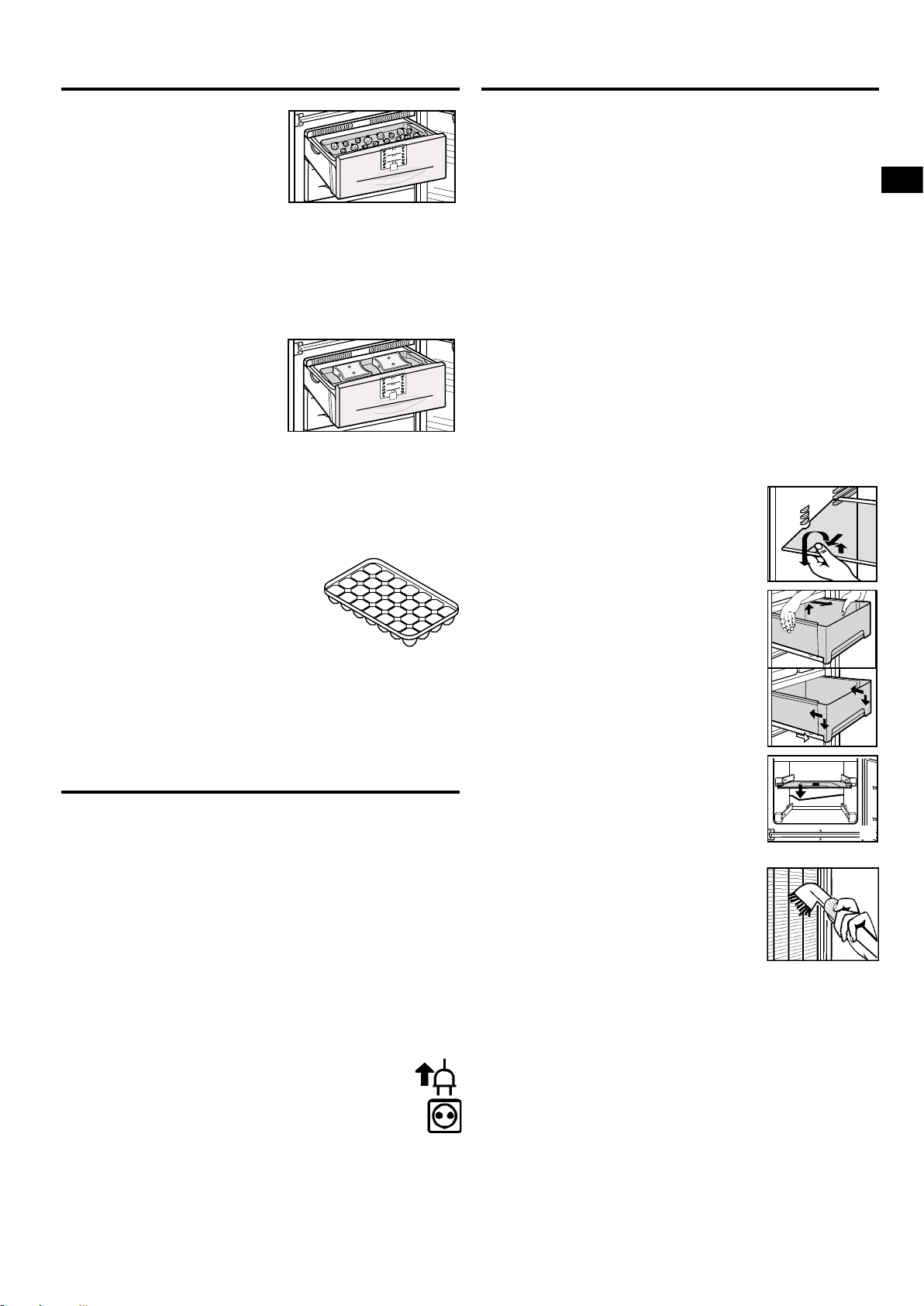
Freezer tray*
This is used for gently freezing
berries, herbs, vegetables and
other small items and prevents
them from sticking together. Items
being frozen will largely retain
their shape, and it will be easier to
remove exactly the right quantity later on.
W Spread the items out loosely on the tray.
W Suspend the freezer tray in one of the top drawers. Free-
ze for 10 to 12 hours, then transfer to a freezer bag or
contain-er and put in a drawer.
W To defrost, spread the frozen items out loosely.
Cold-storage
accumulators*
These prevent the temperature in
the freezer from rising too quickly
in the event of a power failure,
thus preserving the quality of the
food.
W To save space, you can freeze and store the cold-storage
accumulators in the freezer tray.
- To ensure maximum storage time in the event of a power
failure, place the frozen cold-storage accumulators in the
top freezer drawer on top of the food.
Making ice-cubes*
W Fill the ice-cube tray with water.
W Place the ice-cube tray in the appli-
ance and leave it to freeze.
W The ice-cubes can be removed from
the tray by twisting or by holding
upside down for a short time under
running water.
Cleaning
Notes on defrosting
The NoFrost system automatically defrosts the appliance.
In the BioFresh compartment
The water is evaporated by the heat from the compressor;
drops of water on the rear wall are perfectly normal.
W Simply ensure that the defrost water can flow freely th-
rough the drain hole in the rear wall (arrow in fig. A).
In the freezer compartment
Any moisture arising collects on the evaporator and freezes,
and is periodically defrosted and evaporated.
The automatic defrosting system keeps the freezer frostfree and eliminates the time and effort spent on defrosting
manually.
Cleaning
W Before cleaning, always switch off the appliance.
Disconnect from the mains or unscrew or remove the fuse.
W Clean the outer walls, inside and equipment by hand with
lukewarm water and a little detergent. Because of the risk
of injury and damage to the appliance, steam clean-ing
equipment should not be used.
W We recommend using a soft cloth and an all-purpose
BN/BNes...6
* Depending on model and options
clean-er with a neutral pH value. Only use food compatible
cleaning and care agents on the inside of the appliance.
W Use a commercially available stainless-steel cleaning
agent for stainless-steel appliances*.
- In order to achieve best possible protection, apply a
stainless-steel care agent uniformly in grinding direction
after cleaning. Points which are darker at the start and a
more intensive coloration of the stainless-steel surface are
normal.
- Do not use abrasive sponges or scourers, do not use concentrated cleaning agents and never use cleaning agents
containing sand, chloride or acid or chemical solvents, as
these would damage the surfaces and could cause corrosion.
W Do not allow cleaning water to run down the drain gulley
or to penetrate the ventilation grilles or electrical components. Dry the appliance.
- Remove the protective film from the decorative trims*.
- Do not damage or remove the type plate on the inside of
the appliance. It is very important for servicing purposes.
W To clean the storage shelves:
- lift the shelves, slide forwards and remove.
Always insert shelves with the guard bar at the back poin-
ting upwards, otherwise food may freeze
onto the rear wall.
- The glass shelves are fitted with stops to
prevent them being pulled out accidentally.
W To clean the BioFresh drawers, pull the
drawers right out, grip at back and lift out
(fig. M1).
- To re-insert: place the drawers on the
extended rails - the rails must align with
the front of the drawer - and slide in
(fig. M2).
- Simply pull the drawer cover out towards you. When re-inserting, make
sure the bearing pins snap into place in
the grooves.
The drawer and the cover must be flush
with one another vertically.
W Clean the drain hole in the rear wall fre-
quently, fig. N, arrow. If necessary, clean
with a thin object, e.g. a cotton swab
or similar.
W The dust should be removed from the
refrigeration unit and heat exchanger
- metal grid at the back of the appliance
- once a year. Dust deposits increase
energy consumption.
W Ensure that none of the wires or other
components are dislodged, bent or
damaged.
W Then connect/switch on the appliance and start to insert
the food to be frozen as the temperature drops.
If the appliance is to be left switched off for any length of
time, empty the appliance, disconnect from the mains, clean
as described above and leave the door open so as to avoid
odours.
19
GB
Page 19

Troubleshooting
Instructions for installation and
modification
Your appliance is designed and manufactured for a long life
span and reliable operation.
If a malfunction nonetheless occurs during operation, check
whether it is due to an operating error. Please note that even
during the warranty period the resultant servicing costs in this
case will have to be borne by the owner.
You may be able to rectify the following faults by checking the
possible causes yourself:
Malfunction Possible cause and remedy
Appliance does not work, display is off
- Is the appliance switched on properly?
- Is the mains plug properly inserted in the socket?
- Is the socket fuse intact?
The interior light does not come on
- Is the BioFresh compartment switched on?
- Has the door been open for more than 15 minutes?
- The bulb is defective. Change the bulb as described in
"Interior light".
Loud running noise
- Is the appliance standing firmly on the floor, or does the
compressor cause nearby items of furniture or objects to
vibrate? If necessary, move the appliance slightly, align by
adjusting the adjustable feet, or move bottles and containers apart.
- Burbling noises are normal. These are caused by the
refrigerant flowing round the refrigerant circuit.
A short clicking sound: This will be heard whenever the
refrigeration unit (the motor) switches on or off auto-matically.
Motor noise: This will be slightly louder for a brief period
when the refrigeration unit switches on. The refrigerating
capacity will increase when the SuperFrost function is
activated, fresh food has just been placed in the appliance
or the door has been left open for a while.
The audible warning signal sounds, the temperature is
not cold enough
- Have you put too much fresh food into the freezer without
activating SuperFrost? (See "SuperFrost")
- Does the door close properly?
- Is the appliance sufficiently well ventilated?
Clear ventilation grilles if necessary.
- Is the ambient temperature too hot?
(See "Safety regulations")
- Has the appliance been opened too often or left open
too long?
- If applicable, wait until the appliance reaches the
required temperature itself.
appears in the display
- There has been a power failure; proceed as described in
"Power failure/FrostControl display".
The outside of the appliance may feel warm in places
- That is quite normal. The heat from the cooling circuit is
used to avoid the formation of condensate.
Customer service and type plate
If none of the above causes apply and you cannot rectify the fault yourself, or if the temperature display reads
"F 0" to " F 5", this means that there is a fault. Please contact
your nearest customer service department (see enclosed list
for addresses). Give the fault num-
ber displayed, together with the
type designation 1,
service number 2 and
appliance number 3
as given on the type plate, so as to
ensure rapid, accurate servicing. The
type plate is located inside the appliance on the left-hand side.
Leave the appliance shut until the customer service engineer
arrives so as to prevent any further cold loss.
Do not install the appliance side-by-side with another refrigerator or freezer. This is important to prevent condensation
and consequential damage from it.
This does not apply to models with side-wall heating. They
are designed for side-by-side installation with this refrigerator/freezer.
Contact your dealer for more information. Attachment instructions are supplied in the accessories bag of the appliance with side-wall heating.
Installation dimensions
For the external dimensions of the appliance, see fig. S.
Changing over door hinges
Fig. T. The door hinges can be changed from one side to the
other if required:
Only change over door hinges when mains plug is disconnected!
W With the door open, lever out plinth panel 1 on the hinge
side with a screwdriver and remove from front.
- Lever out cover 2 with a screwdriver. Close door.
- Unscrew screw M5 3.
W Pull hinge component 4 with hinge pin 5 out from un-
derneath and remove.
- Open door, lift out at bottom and remove.
- Pull middle hinge pin 6 out from underneath.
- Tilt out top door and lift off from underneath (with version I,
do not lose spacer sleeve 9).
W Transfer all hinge components onto the other side:
W Top: depending on version, proceed as follows:
Version I (visible operating panel): Lever out covers 8
with a screwdriver at the front and remove at an angle
from below. Remove hinge pin 7 and insert on the opposite side. Use the hexagon socket on the open-ended
spanner provided (spanner width 5). Fit covers 8 again:
insert at rear and click into place at front.
Version II (concealed operating panel): Lift up cover 8 on
handle side, push outwards; lift up cover on hinge side and
pull off.
- Unscrew earthing plate cm: first earthing screw cl, then
inner retaining screw cq.
- Unscrew hinge 9: first undo earthing screw cl, then retaining screws cq. Fit hinge 9 to opposite side: for easy
assembly, fit hinge from above and first tighten with the
upper retaining screw cq M5, then screw cq and finally
earthing screw cl M4.
- Turn earthing plate cm through 180° and screw tight again
on the new handle side: first retaining screw cq, then earthing screw cl.
- Insert hinge pin 7 in the other retaining hole. Use the
hexagon socket on the open-ended spanner provided
(spanner width 5).
- Fit covers 8 again: insert hinge-side cover by sliding outwards and click into position; insert handle-side cover by
sliding inwards and click into position.
W Centre: Change over cover bl with hinge bm: unscrew
screws, lift off cover bl and hinge bm to the side, turn
through 180° and replace on the other side, remove
hinge bushing bn and re-insert from top.
W Bottom: Using a screwdriver, remove the spacer bo and
replace on the other side.
W Re-attach the doors: Remove plugs bp from the door
mounting points and re-place on the other side.
- Suspend top door in hinge pin 7 (with version I, do not
forget to use spacer sleeve 9), close door.
20
BN/BNes...6
Page 20

Instructions for installation
S
[mm]
1841
597
631
614
644
1179
56,
5
1
0
T
SW5
*
SW5
1
8
0
°
1
2
3
4
5
6
7
9
9
8
8
8
8
10
11
12
13
15
I
II
*
18
20
20
21
21
9
T1
15
13
*
16
*
17
14
7
25
25
Torx 15
5
8
0
6
3
1
m
in
.
5
0
ca. 36
[mm]
min.
300
cm
2
U
4
3
2
1
9
25
20
Torx 25
and modification
- Slide middle hinge pin 6 into the door mounting from
below through the hinge bm. Make sure the door is flush
with the body of the appliance; adjust if necessary using
the slots on the hinge.
- Suspend lower door, close.
- Rotate hinge component 4 by 180°, remove hinge pin 5,
turn by 180° and replace, mind the locking facility. Mount
both parts in the hinge bq: slide the pin into the door
mounting through the hinge, tilt in the hinge component,
slide up and attach with screw 3.
W Align the door flush with the body of the appliance using
the slot on the hinge bq, then tighten screw 3.
W Attach the plinth panel 1 and click into place by pressing.
W With the door open, insert the cover 2 in the plinth panel
at the front and click into place at the back.
W Transfer* door handles br and plugs bt. With the door
open, carefully lift out the pressure plates* bs at the front
and slide away; unscrew handle using a Torx® or Phillips
screwdriver*.
Re-assemble in reverse order: replace the pressure plates
and click into position.
Insertion into row of kitchen units
Fig. U. The appliance can be installed in a row of kitchen
units. To adapt the height of the appliance to the surrounding furniture a top unit 1 can be added.
A gap of at least 50 mm depth must be provided behind and
along the entire width of this unit so as to ensure sufficient
ventilation. The area of ventilation underneath the ceiling
should be at least 300 cm2. The greater the area the more
economically the appliance will run.
W When installing with standard kitchen units (max. depth
W When setting up the appliance next to a wall 4, a mini-
1 top unit 3 kitchen unit side panel
2 refrigerator/freezer 4 wall
580 mm), the appliance can be set up right next to the
kitchen unit. The door protrudes 34 mm from the side of
the kitchen unit and 51 mm at the front. This enables it to
be opened and closed without difficulty.
mum distance of 36 mm must be provided on the hinge
side between the appliance and the wall (for the handle
when the door is open).
GB
All types and models are subject to continuous improvement
and the manufacturer therefore reserves the right to make
modifications in the shape, equipment and technology.
BN/BNes...6
21
Page 21

Side-by-Side
Side-by-Side connecting set
Home Connecting set
Home
Castors
Assembly
Installation
Handle length
SBS range
1/ 20
1/ 20
Page 22

Connecting set
Page 23

New for the SBS refrigerator-freezer
Side-by-Side
combinations
• The SBS refrigerator-freezer
combinations come with a new
connecting set.
• The plinth panel of the
refrigerator-freezer combination
is one piece.
• The lengths of the handles of
the appliances 184 cm high are
matched. The handle of the
refrigerator is as long as the two
Home Connecting set
Connecting set
Castors
Assembly
Installation
handles of the refrigeratorfreezer combination together.
• The transport position of the
lever handles is discontinued.
Handle length
SBS range
3/ 20
Page 24
New connecting set
Side-by-Side
The new connecting set comprises:
• A one-part plinth panel made of high-grade stainless steel, which is clipped onto both appliances.
• A stainless steel strip to cover the gap between the appliances.
• Sets of fixing parts for firmly screwing the appliances together at the rear.
• A coated panel to conceal the top screw fitting on the front side.
• Height-adjustable rear castors, which are adjustable from the front. The range of adjustment is 16 mm.
For the customer these changes mean that a unitary look is created and the two appliances are
easier to align and install.
Home Connecting set
Connecting set
Castors
Assembly
Installation
Handle length
SBS range
4/ 20
Page 25

Side-by-Side
New connecting set
Additional fastening by screw fittings
concealed by the cover panel
consisting of two flexibly interconnected
parts.
Ideal alignment and fixing of the two appliances:
Through accurate screw fittings
of the appliances at the front top and bottom and
at the back top and bottom.
A coated panel conceals the screw fitting at the
top front.
Home Connecting set
Connecting set
Castors
Assembly
Installation
A high-grade stainless steel strip
covers the gap between the
appliances.
Handle length
SBS range
5/ 20
Page 26

New connecting set
Side-by-Side
Delivery
The single appliances are delivered without plinth panel and without the
upper cover panel next to the electronic panel.
The one-part plinth panel and the cover panel from the new connecting
set are used for assembling the appliances.
• The one-part, stainless steel plinth panel is packed separately.
• The stainless steel strip is affixed directly to the freezer or to the
appliance with freezer compartment.
Home Connecting set
Connecting set
• Other small components and the assembly instructions of the SBS
connecting set are also packed with this appliance.
• The height-adjustable castors are already fitted to both appliances.
Castors
Assembly
Installation
Handle length
SBS range
6/ 20
6/ 20
Page 27

Feet with
castors
Page 28

Side-by-Side
NEW: height-adjustable castors
Home Connecting set
Ideal, extremely user-friendly alignment of the appliances:
• rear castors adjustable from the front
• the range of adjustment is 16 mm
Castors
Castors
Assembly
Installation
Handle length
SBS range
8/ 20
8/ 20
Page 29

Assembly
Page 30

Side-by-Side
Connecting set
top back
top front
bottom front
bottom back
Home Connecting set
Castors
Assembly
Assembly
Installation
Handle length
SBS range
10 / 20
Page 31

Front assembly cover
Side-by-Side
The cover is snapped onto the gap between the two control panels.
It is important to pay attention that the outer faces of the cover
form a flush finish with the control panels. Therefore the cover is
extendable.
Home Connecting set
Castors
Assembly
Assembly
Installation
Handle length
SBS range
11 / 20
Page 32

Side-by-Side
The plinth panel is pushed onto the bearing supports until the detent
hooks audibly lock snap into place in them.
To detach the plinth panel, the detent hook on the underside of the
plinth panel has to be pushed with one hand in the direction of the
appliances and held there. With the other hand the plinth panel can
now be drawn away from the appliance.
Plinth panel
Home Connecting set
Castors
Assembly
Assembly
Installation
Handle length
SBS range
12 / 20
Page 33

Side-by-Side
Height-adjustable feet
The rear feet are adjusted using a socket wrench
back
front
Home Connecting set
back
Castors
Assembly
Assembly
front
The front feet are adjusted using a spanner
Installation
Handle length
SBS range
13 / 20
Page 34

Side-by-Side
Fitting the strip
Plastic strip, top
Stainless steel strip, front
Home Connecting set
Castors
Assembly
Assembly
Installation
Handle length
SBS range
14 / 20
14 / 20
Page 35

Installation
Page 36

Side-by-Side
Site conditions
Home Connecting set
Castors
The SBS freezers and the SBS appliances with
freezer compartment come with a heating system in
one of the side walls, i.e. the appliances must always
be on the left as viewed by the user.
Assembly
Installation
Installation
Handle length
SBS range
16 / 20
16 / 20
Page 37

Handle length
Page 38

Matched handle lengths
Side-by-Side
The lengths of the handles of the
appliances 184 cm high are matched.
The handle of the refrigerator is as long
as the two handles of the refrigeratorfreezer combination together.
The transport position of the lever handles
is discontinued.
Home Connecting set
Castors
Assembly
Installation
Handle length
Handle length
The length of the handles
of the solo appliances is
also changed.
SBS range
18 / 20
18 / 20
 Loading...