

Page 1
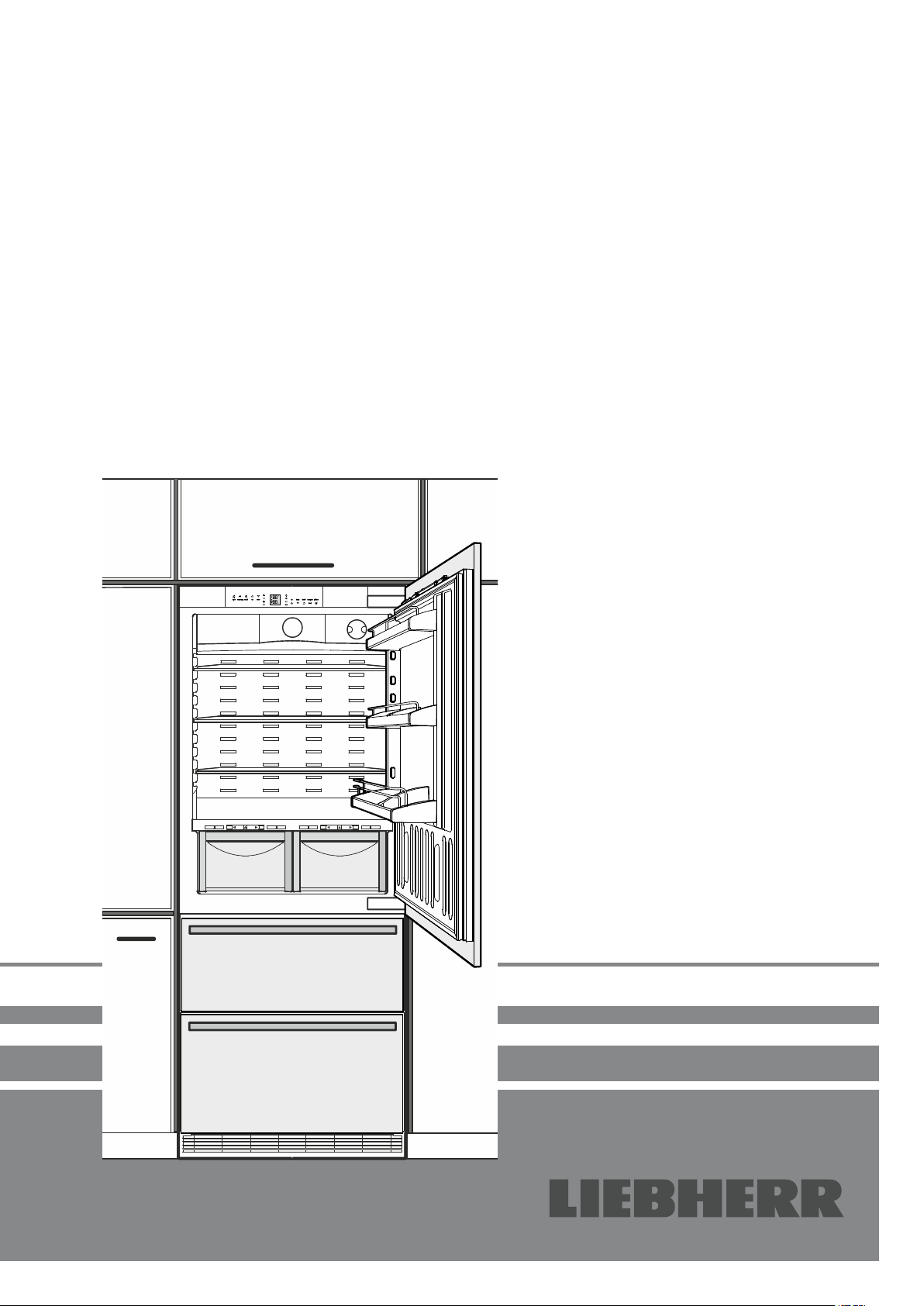
Installation instructions
for NoFrost combined refrigerator-freezers
7083 461-00
ECBN 5066
Page 2
Content Page
Setting up ...................................................................................2
Electrical connection ..................................................................2
Appliance venting .......................................................................2
Door swing clearance .................................................................2
Appliance dimensions ................................................................3
Installation dimensions ...............................................................3
Mounting the anti-tipping device ................................................4
Mounting options ........................................................................4
Connection to the water supply ..................................................5
Leveling the appliance ...............................................................7
Fastening the appliance in the recess ........................................7
Adjusting the refrigerator door ....................................................7
Adjusting the front of the drawer .................................................7
Mounting the ventilation grille .....................................................8
Before fitting the door panels .....................................................9
Panel dimensions .......................................................................9
Mounting the attachment brackets onto the door panels .........10
Mounting the refrigerator panel ................................................11
Mounting the freezer panels .....................................................13
Changing over door hinges ......................................................13
Setting up
• Avoid positioning the appliance in direct sunlight or near cookers,
radiators and similar sources of heat.
• The floor on which the appliance stands should be horizontal
and level.
• The ventilation grilles should not be obstructed. Always ensure
that there is good ventilation and that the outward flowing air is
able to escape.
• Standard EN 378 specifies that the room in which you install
your appliance must have a volume of 1 m³ per 8 g of R 600a
refrigerant used in the appliance, so as to avoid the formation of
inflammable gas/air mixtures in the room where the appliance
is located in the event of a leak in the refrigerant circuit. The
quantity of refrigerant used in your appliance is indicated on the
type plate on the inside of the appliance.
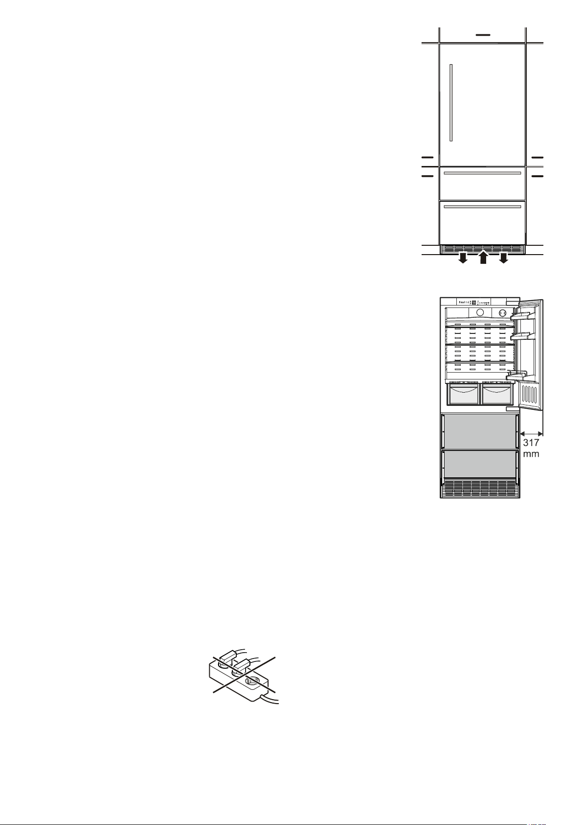
Appliance venting
The required air flow is directed
through the plinth.
It is important to use the provided
ventilation grille for the ventilation
opening.
This opening must not be covered.
Failure to use the supplied grille
can result in product failure and
will void the warranty.
Door swing clearance
Please allow for door swing clearance
at locations next to a wall.
The illustrated measurement is without mounted front panels.
Be sure to add your panel thickness
and handle depth to this measurement in order to avoid interferences.
Electrical connection
Only operate the appliance with alternating current (AC).
The permissible voltage and frequency are indicated on the type
plate. The position of the type plate is shown in the description of
the appliance.
The socket must be properly earthed and protected by a fuse.
The tripping current of the fuse must be between 10 A and 16 A.
The socket must not be situated behind the appliance and must
be easily accessible.
Do not connect the appliance using an extension cable or extension socket.
Do not use stand-alone inverters (conversion
of direct current to alternating/three-phase current) or energy-saving plugs. Risk of damage
to the electronic control system!
2
Page 3
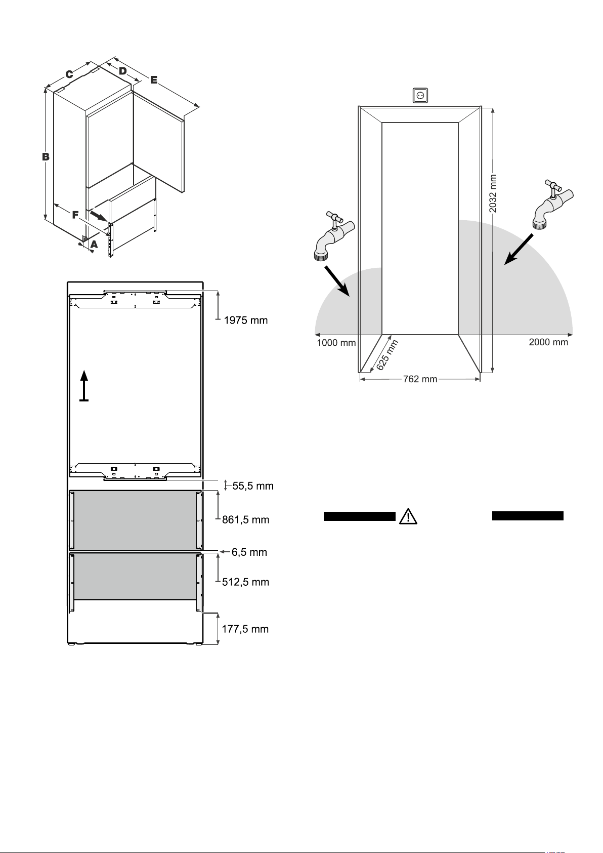
Appliance dimensions
Installation dimensions
The location of the socket can within a radius of 2000 mm from
the appliance top center.
A = 76 mm
B = 2027 mm
C = 757 mm
D = 610 mm
E = 1413 mm
F = 952 mm
This type of dimension
line indicates the height
measured from the floor.
The ice maker is fitted in the freezer compartment of the combined
refrigerator-freezer. It must be connected to the mains water supply to work.
The water shut-off valve must be positioned within the areas
marked in grey.
Important
Do not install the shut-off valve behind the appliance.
WARNING!
The water shut-o valve must not sit directly above the
socket!
The gap between the water shut-o valve and the socket
must comply with the regulations of the country in which
the appliance is used!
3
Page 4
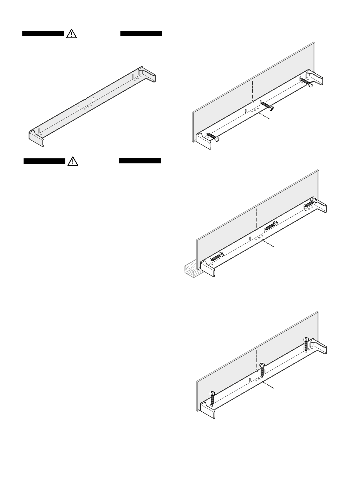
Mounting the anti-tipping device
Mounting options
WARNING!
The supplied anti-tipping bracket must be installed in all
cases. This prevents the appliance from tipping over when
the fully loaded door is opened.
CAUTION!
Ensure that there are no electric cables or water pipes in the
wall section to which the anti-tipping bracket is to be secured.
These could be damaged during installation.
Installation:
1. Mark the centre line of the appliance on the floor.
Align the anti-tipping bracket centre to the centre line.
Mounting the bracket with the wall studs.
Mounting with plugs to concrete walls.
3 Screws 6 x 60 mm
Wall
Floor
Mounting with the wall plate turning in
the screws at an angle.
3 Screws 6 x 60 mm
2. Depending on the constitution of the floor and wall, use any pos-
sible mounting option as shown in chapter Mounting Options.
The screws (6 x 60) are supplied with the accessory pack.
Important!
If the floor slopes down sideways, the anti-tipping
bracket must be fitted horizontally. Lay down spacers
in the appropriate positions.
Wall
Floor
Mounting with wooden floors.
Mounting with plugs to concrete floors.
3 Screws 6 x 60 mm
Wall
Floor
4
Page 5

Connection to the water supply
Installation
1. Place the appliance in front of the installation recess.
Safety instructions and warnings
• Do not connect to the water supply while the combined refrigeratorfreezer is connected to the electricity supply.
• The connection to the mains water supply may only be
made by trained personnel.
• The water quality must comply with the drinking water
directives of the country in which the appliance is used.
• The ice maker is designed exclusively to make ice cubes in
quantities required by a household and may only be operated
with water suitable for this purpose.
• All repairs and work on the ice maker may only be carried out by
customer service personnel or other trained personnel.
• The manufacturer cannot accept liability for damage caused
by a faulty connection to the mains water supply.
Water pressure
The water pressure must be between 0.15 and 0.6 MPa (1.5 6 bar).
Important:
If the water filter is inserted in the appliance, the water
pressure must lie between 0.3 and 0.6 MPa (3 - 6 bar).
If the water pressure with the inserted water filter is too low,
this may cause the ice maker to malfunction.
2. Apply cover strips above, between and below the securing
plates on the side walls of the
appliance.
Cut the cover strips to the right
length for this purpose.
Fit the adhesive cover strips
leaving a gap of 6,5 mm to each
securing plate. This ensures
problem-free fitting of the covers.
2.
The water supply to the appliance must be through a cold
water pipe that can withstand
the operating pressure and complies with the hygiene regulations. For this, use the stainless
steel hose supplied (length 3 m).
3. Insert the bent section of the hose
through the opening at the right side
of the appliance.
3.
4. Move the hose to the front and con-
nect with the valve connector.
Be sure the connection is tightly
arranged.
Valve connector
4.
5
Page 6

5. Locate the water hose into the rail of
the appliance base.
5.
6. Route the mains cable towards the socket.
7. Route the water hose towards the water shut-off tap.
WARNING!
Do not connect the appliance to the power supply until the
installation is completed.
CAUTION!
Lay the mains cable and the water hose in such a way that
they will not be damaged when the appliance is slid into
the installation recess.
8. Push the appliance slowly into the recess until the compressor
mounting plate touches the anti-tipping bracket.
8.
9. Fill the hose with water and connect to the shut-off tap.
Be sure the connection is tightly arranged.
Open the shut-off tap and check the system for leakage.
Important!
After the ice maker has been switched on, the water supply system
must be bled. See the section Bleeding the ice maker in the
operating instructions.
6.
7.
6
Page 7

Leveling the appliance
1. Adjust the height of the appliance at the front by twisting the
leveling feet
Turn the spanner counterclockwise to raise the appliance front
and clockwise to lower it.
Position the spanner accordingly(
2. Adjust the height of the appliance at the rear by turning the adjusting bolts
provided.
1
. Use the open-ended spanner provided.
).
1
2
. Use a 1/4" box spanner or the Torx 25 wrench
Adjusting the refrigerator door
The lateral tilt of the refrigerator door can be adjusted if required.
Undo screws
(Allen key A/F 2.5).
1
. Adjust the lateral tilt using the grub screw 2
3. Rotate leveling feet
1
until firmly in place against the floor.
WARNING!
To prevent the appliance from tipping forward the leveling feet
1
must have contact with the floor.
Adjusting the front of the drawer
If required, the front of the freezer drawers can be adjusted.
Transfer the screws shown in the illustration (on the left and right
sides of the freezer drawer) individually to the long slots below.
Tighten the screws in the front of the drawer once it is in the right
position.
Fastening the appliance in the recess
Once in the recess, secure the appliance to
the body of the unit using the securing
plates (4 x 16 screws).
Then click the covers supplied into place.
Side view of the freezer drawer
pulled out
7
Page 8

Mounting the ventilation grille
Pull out the bottom freezer drawer.
1. Remove the blue protection film from the dust filter
provided and insert the filter into its opening
in the plinth
bottom, press down the button
and click into place.
. Engage the filter at the
1.
2. Remove the locking pins of
both supports. The supports
are provided with the appliance accessory pack.
5. Insert the locking pins to block the supports.
5.
6. Install the ventilation grille.
The grille has bolts on the inside (see detail in the drawing
below). These bolts must be inserted into the holes of the
supports.
3. Insert the supports for the ventilation grille
on the left and right sides in the motor
compartment.
2.
3.
6.
7. Adjust the height of the ventilation grille.
• Loosen the grub screws at the front of the grille (Allen key
A/F 2.5).
• Adjust the ventilation grille to the desired height.
• Tighten the grub screws.
4. The front edge of the brackets
is flush with the front of the
ventilation grille.
Adjust the supports accordingly.
8
7.
4.
Page 9

Before fitting the door panels
Remove the cover 1 and unscrew the top and bottom attachment brackets
brackets will be mounted onto the refrigerator door panel.
2
from the refrigerator door. These attachment
Important!
The securing nuts are needed for re-mounting the preassembled door panel onto the refrigerator door.
Panel dimensions
Min. panel thickness = 16 mm
Max. panel thickness = 19 mm
Maximum panel weight
Refrigerator panel = 27 kg
Freezer drawer panel = 10 kg
3
Unscrew the attachment brackets
These attachment brackets will be mounted onto the freezer panels.
from the freezer drawers.
Important!
The screws are needed for re-mounting the pre-assembled
freezer panels onto the freezer drawers.
9
Page 10

Mounting the attachment brackets onto the door panels
1. Draw a line 1041 mm from the bottom side of the door panel.
2. Draw a further line 107.5 mm from the bottom side of the door panel.
3. Align one of the refrigerator door attachment brackets to the top line, as shown in the illustration below, and secure with at least
6 screws (4 x 14).
4. Align the second refrigerator door attachment bracket to the bottom line, as shown in the illustration below, and secure with at
least 6 screws (4 x 14).
5. Secure each of the attachment brackets that have been removed from the freezer drawers using 3 screws (4 x 14), as shown in
the illustration below.
Refrigerator door panel
Freezer drawer panel
Freezer drawer panel
10
Page 11

Mounting the refrigerator panel
1. Screw in the adjusting pins on the underside of the refrigerator
door completely (fig. A).
fig. A
4. Close the refrigerator door and check the height of the panel.
5. Adjust the height of the panel if necessary. Undo the securing
nuts and use the adjusting pins to adjust (fig. C).
fig. C
2. Open the refrigerator door and suspend the refrigerator panel
on the top adjusting pins (fig. B).
3. Screw securing nuts onto the adjusting pins and slightly tighten.
fig. B
6. Adjust the panel horizontally (using the long slots in the attachment bracket) (fig. D).
7. Tighten the securing nuts.
fig. D
11
Page 12

8. Remove the adjusting pins (bottom of the refrigerator door)
until these touch the attachment bracket (fig. E).
10. Undo the three screws on the top of the attachment bracket,
adjust the door panel as displayed in fig. G and then retighten
the screws. The same procedure can be carried out for the
bottom attachment bracket.
fig. E
9. Screw on the securing nuts and tighten (fig. F).
fig. F
fig. G
11. Click the top and bottom covers into place
1 (fig. H)
Insert the cover strip provided 2 between refrigerator door
and panel.
12
fig. H
Page 13

Mounting the freezer panels
1. Pull out the top freezer drawer and screw on the pre-assembled
panel. The same screws must be used as those used to screw
on the attachment brackets (3.5 x 13).
2. Close the freezer drawer and check the position of the panel.
Adjust the height of the panel by undoing the left and right
screws. Tighten the screws.
3. Pull out the bottom freezer drawer and mount the panel in the
same way.
4. For both drawers, cover the gap between the drawer and the
panel with the cover strips supplied. Remove the protective
film from the trim and insert into the gap at the top.
3.5 x 13 mm
Changing over door hinges
Door hinges should only be changed by a trained expert.
WARNING!
Do not try to change over the door hinges yourself. The
refrigerator door hinges are fitted with strong closing
springs. If the hinge accidentally snaps shut, this can lead
to serious injury.
13
Page 14

14
Page 15

15
Page 16

Liebherr Hausgeräte Lienz GmbH * Dr.-Hans-Liebherr-Strasse 1 * A-9900 Lienz ** www.liebherr.com
 Loading...