

Liebert CRH204, CRH008, CRH011, CRH014, CRH016 Service Manual
...
R [004-032]
HIGH PERFORMANCE AIR COOLED CHILLER
SERVICE MANUAL
English
Cod. 273044
Rev. 25.05.2005
Issued by T.D.Service


Caution
It is recommended that:
S the manual is retained for the entire service life of the machine;
S the user reads the manual carefully before carrying out any operations on the machine;
S the machine is used exclusively for the purpose for which it is intended; incorrect use of the machine shall release the
manufacturer from any liability.
This manual has been prepared to enable the end ---user to carry out only those operations that can be done with the panels
closed. Any operations that require the opening of doors or equipment panels must be carried out only by qualified personnel.
Each machine is equipped with an electric isolating device which allows the operator to work in conditions of safety. This
device must always be used to eliminate risks during maintenance (electric shocks, scalds, automatic restarting, moving
parts and remote control).
The panel key supplied with the unit must be kept by the person responsible for maintenance.
For identification of the unit (model and serial no.) in case of the necessity for assistance or spare parts, read the identification
labels affixed to the outside and inside of the unit.
IMPORTANT: This manual may be subject to modification; for complete and up --- to --- date information the user should
Index
1-- Introduction 1...............................................................................
1.1 --- Foreword 1....................................................................................
1.2 --- Responsibility 1................................................................................
1.3 --- Inspection 1...................................................................................
1.4 --- General description 1............................................................................
2 -- Preliminary Operations 1....................................................................
2.1 --- Operating limits 1...............................................................................
2.2 --- Sound pressure levels 2.........................................................................
2.3 --- Transport 2....................................................................................
2.4 --- Foundations 2..................................................................................
2.5 --- Service area 2..................................................................................
3 -- Installation 2................................................................................
3.1 --- Aeraulic connections 2..........................................................................
3.2 --- Hydraulic connections 2.........................................................................
3.3 --- Connection of the safety valve discharge 3.........................................................
3.4 --- Electrical connections 4..........................................................................
4 -- Start--Up and Operation 5...................................................................
4.1 --- Initial check 5..................................................................................
4.2 --- First start ---up (or after a long stop) 5...............................................................
4.3 --- Starting and stopping 5..........................................................................
4.4 --- Chillers serving special plants 5...................................................................
4.5 --- Freecooling 5..................................................................................
4.6 - -- Microprocessor control 5.........................................................................
5 -- Refrigerant and Oil Charge 5.................................................................
5.1 --- Refrigerant charge 5............................................................................
5.2 --- Oil charge 6...................................................................................
6 -- Safety Devices Settings 6....................................................................
6.1 --- Setting thermostatic expansion valve 7.............................................................
7 -- Maintenance 7..............................................................................
7.1 --- Spare parts 7..................................................................................
7.2 --- Dismantling the unit 7...........................................................................
8 -- Options and Accessories 8...................................................................
8.1 --- Pump set 8....................................................................................
8.2 --- Water chiller with partial heat recovery (20%) 8......................................................
8.3 --- Water chiller with total heat recovery (100%) 8.......................................................
8.4 --- Hydraulic circuit accessories 8....................................................................
8.5 --- Water chiller with inertia tank 9....................................................................
always consult the manual supplied with the machine.
Ta b l e s 10.........................................................................................
Drawings 20......................................................................................
Circuits 35........................................................................................

1 --- Introduction
C
1.1 --- Foreword
This handbook is aimed at enabling both the installer and the operator to carry out the correct installation, operation and maintenance of the refrigerating machine, without damaging it or causing injuries to the relevant staff.
The handbook is thus an aid for the qualified staff in the arrangement of the specific equipment for the correct installation, operation and maintenance in compliance with the local regulations
in force.
The MATRIX R water chillers can be identified as follows:
RH004
Cooling C apacity “kW”
Nominal cooling capacity / 10
Compressor:
H Hermetic Scroll
Version:
R Radial
Execution:
C Chiller
S Superchiller
1.2 --- Responsibility
Liebert Hiross accepts no present or future responsibility for
damage to persons, things or to the machine itself due to operators’ negligence, failing to comply with the installation, operation
and maintenance instructions of this handbook, failed application of the safety norms in force for the system and the qualified
staff charged with the operation and maintenance.
1 . 3 --- I n s p e c t i o n
All units are fully assembled and wired in the manufacturing
plant. Before shipment they are charged with the necessary
quantities of refrigerant and oil and then tested at the operating
conditions normally required by the customer. The machine’s
hydraulic circuit is equipped with drain plugs and open vent
valves; the free ---cooling coils are supplied dry to avoid possible
problems due to frostin the storage period. Immediately inspect
the machine carefully on delivery to check for damage during
transportation or missing components; possible claims must be
made immediately to the carrier and the factory or its representative.
1 . 4 --- G e n e r a l d e s c r i p t i o n
MATRIX R units with air ---cooled condensers have been designed and manufactured for producing chilled water.
They are also available in versions with a built -- -in freecooling
module, in versions with heat recovery for simultaneous heating
of thermal circuit water, with a pump assembly installed on the
machine and/or inertial buffer tank inside the machine; the chilling units can be equipped with several options indicated in the
price list.
The ”MATRIX R” product line has been designed utilising the
state---of---the---art techniques available nowadays in the industry, and includes all the components necessary for automatic
and efficient operation.
The Matrix R units are specifically designed for indoor installation (protected from weather agents), for the connection with
ducts of condensation air in machine intake (if present) and
outlet.
Each unit is completely factory assembled; after evacuation, the
necessary quantity of refrigerant is added to the refrigerant circuit(s) and the unit is tested.
All the unitsare equipped with one or two independent refrigerating circuits, each one composed of: an air --- cooled condenser,
a hermetic Scroll compressor and a braze---welded plate evaporator. The components of the liquid line are the charging valves,
filters - --dryers, solenoid valve, shut--- off valve, moisture indicator
and thermostatic expansion valve.
The hydraulic circuit -- - with max. working pressure 5 bar --- is
made up on mod. 004---016 of hydraulic lines both in steel and
flexible EPDM rubber, connected by fittings and threaded joints,
on mod. 017 --- 032 of carbon steel pipes connected with
grooved---end (Victaulic) fittings and couplingsand include also
a flow switch (optional) and, in the freecooling versions, chilled
water coils and a three - --way valve.
The hermetic scroll compressors are complete with the following
protection/safety devices: oil heater (if necessary), electronic
protection monitoring the temperature of the motor windings
and the direction of rotation (the latter may be enclosed in the
electronics of the compressor or external, depending on the
model).
Fans are radial type, with aluminum reverse curved blades and
structure, statically and dynamically balanced, directly coupled
to a motor with external rotor. It is always available the fan speed
controlwhich normally is achieved through an adjuster with continuous speed modulation.
By simply modifying the parameters(of the Microfacemicroprocessor control), limiting the fan max. rotation speed, it is possible
to change the useful air static pressure (equal to the difference
of the static pressure between the delivery and suction ducts
connected with the unit).
The ”MATRIX R” water chillers are controlled by the ”MICROFACE” microprocessor, managing all the unit operating conditions.
The user can change and/or modify the operating parameters
through the display keyboard installed on the electrical panel.
The electrical control board is equipped with all the safety and
operating devices required for reliable operation. The compressor motors are equipped with protection on all three phases and
are started by three --- pole contactors.
2 --- Preliminary Operations
2.1 --- Operating limits
The units can operate within the indicated operating limits (see
Tab. 6). These limits apply to new machines, subject to correct
installation and maintenance.
S Ambient air minimum temperature: ---25ûC for Superchiller,
--- 1 0 ûC for Chiller (either Triac or EC fan);
S Maximum outdoor air temperature is in relation to each mod-
el, as indicated in Tab. 6. In any case outdoor temperatures
aver 45ûC are not admitted; such limits are determined by
electrical and electronic components fitted on units;
S Maximum water flow allowed: depending on the pressure
drop corresponding to the required thermal difference (usually not lower than 3.5ûC --- 4 ûC);
S Minimum allowed water flow: compatible with a sufficient
evaporation temperature, to avoid the intervention of the
safety devices (to be evaluated for a thermal difference not
higher than 8ûC);
S Temperature range of the water exiting the evaporator: 4ûC
--- 1 5 ûC;
S Maximum temperature of the water entering the unit: 20ûC;
higher temperatures are allowed only at the system start--up and not during normal operation;
S Maximum glycol concentration: 50% (35% with the optional
pump assembly installed on the machine);
1

S Minimum allowed glycol concentration: depending on the
minimum temperature of the ambient air expected at the
installation site (see Tab. a);
S Maximum difference of air side pressure (between the one
in the delivery duct and the one, possibly negative, in the
coil suction) equal to the max. one indicated in Tab. 9 next
to the max. signal = 10 V set on the microprocessor;
S Maximum pressure of the hydraulic circuit: 5 bar;
S Voltage range for the electric supply: 400 V
phase difference: 3%; tolerance on frequency: 1%.
Storage conditions: ---20ûC ÷ 45ûCforallMATRIXRmodels.
+
/
10%; max.
---
2.2 --- Sound pressure levels
The Tab. 7 shows the noise data for the units in standard configuration (without pumps), operating continuously and measured
at 1 m from the coil side unit, with ducted air delivery and 50 Pa
of useful static pressure, in free field conditions.
The highest noise levels are detected for higher useful static
pressures of the air.
Note:
Avoid positioning in areas with possible reverberation of the
sound waves; acoustically insulate both the delivery and the intake ducts (if installed); failure to do this can adversely effect the
noise levels.
2 . 3 --- T r a n s p o r t
S Handle the unit by lifting it with a crane from above;
S The lifting holes are positioned in the frame’s base (when lift-
ing, use spreader bars to protect the sides, see Fig. 3, Fig. 4
and Fig. 5).
Note:
Place the lifting tubes in the holes in the base indicated by ”LIFT
HERE”. Lock the ends of the tubes with the locking pins and
splits pins as shown in Fig. 3 and Fig. 5. As an alternative (on
mod. 004 --- 016 only), shackles/hooks (optional) fastened at the
base ends can be used as a lifting system: in this case the lifting
point must be on the vertical line passing through the machine’s
centre of gravity (as indicated in Fig. 4) to prevent any load imbalance.
The capacity of the lifting gear must be adequate to lift the load
in question. Check the weight of the units, the capacity of the lifting gear and ropes and the condition and suitability of the aforementioned equipment.
2.4 --- Foundations
S The unit must be placed on a level surface which will support
its weight.
S If necessary, position the unit on suitable anti---vibration sup-
ports that can be supplied as an option (in rubber or spring --type). Refer to the manual ”Installation of the spring anti --vibration supports” for their correct positioning.
S When positioned, level the unit.
Note:
For weight distribution see Fig. 6 and Fig. 7.
Note:
The weights and their distribution refer to standard units without
options; if the pump assembly, or other options are installed on
the machine, add the weights of the installed accessories to
those of the standard units (see Tab. 8).
2.5 --- Service area
S In order to allow free air flow or to enable the ducting installa-
tion and maintenance of the unit, a minimum area must be
left free of obstructions around the unit (see Fig. 1 and
Fig. 2).
S Avoid recirculation of hot air between the outlet and the out-
door intake of the air conveyed in the ducts, otherwise the
unit performance may be impaired or the standard operation can be interrupted.
3 --- Installation
3.1 --- Aeraulic connections
The Matrix R units are arranged with connection flanges for the
air intake and delivery ducts; if the units are ordered with metal
filters to protect the condensing coils, the connection flanges for
theintakesideductingarenotsupplied,asthereisnoductto
enable the cleaning of such filter.
Connect the ducts fitting flexible joints to prevent transmitting
vibrations and to compensate thermal expansion. Check if the
holes on the walls --- where the intake and delivery ducts are
fitted --- are protected by suitable anti---rain grilles (equipped
with pre --- filter like the intake ones) to avoid water or dust to enter
in the chiller.
All fans are adjusted at the same speed, so that it is not necessary to install overpressure dampers next to each fan discharge.
The units are supplied with a setting in the microprocessor for
the max. fan speed of 50 Pa useful pressure; set the max. speed
according to the features required by the installation (see
Tab . 9) .
The units are supplied with the condensation air discharge upwards; during the installation, it is possible to change the position of the air discharge opening (with right or left horizontal
direction) by simply inverting the position of the drilled panel
withtheclosedoneoftherequiredside(seesizedrawings).
3.1.1 -- External air temperature probe installation
Install the external air temperature probe (shipped inside the
electric panel), at the end of the air intake duct.
The bulb must be positioned as much outside as possible but
must not be exposed to direct sunlight or weather agents such
as rain or snow. The unit operation could be jeopardized if these
precautions are not applied.
If the intake side duct is not present, fasten the probe in the room
so that it can correctly detect the external temperature of the coil
intake outer air without being influenced by other external factors
(sun rays, rain or snow, other heat or radiation sources, etc.).
3.2 --- Hydraulic connections
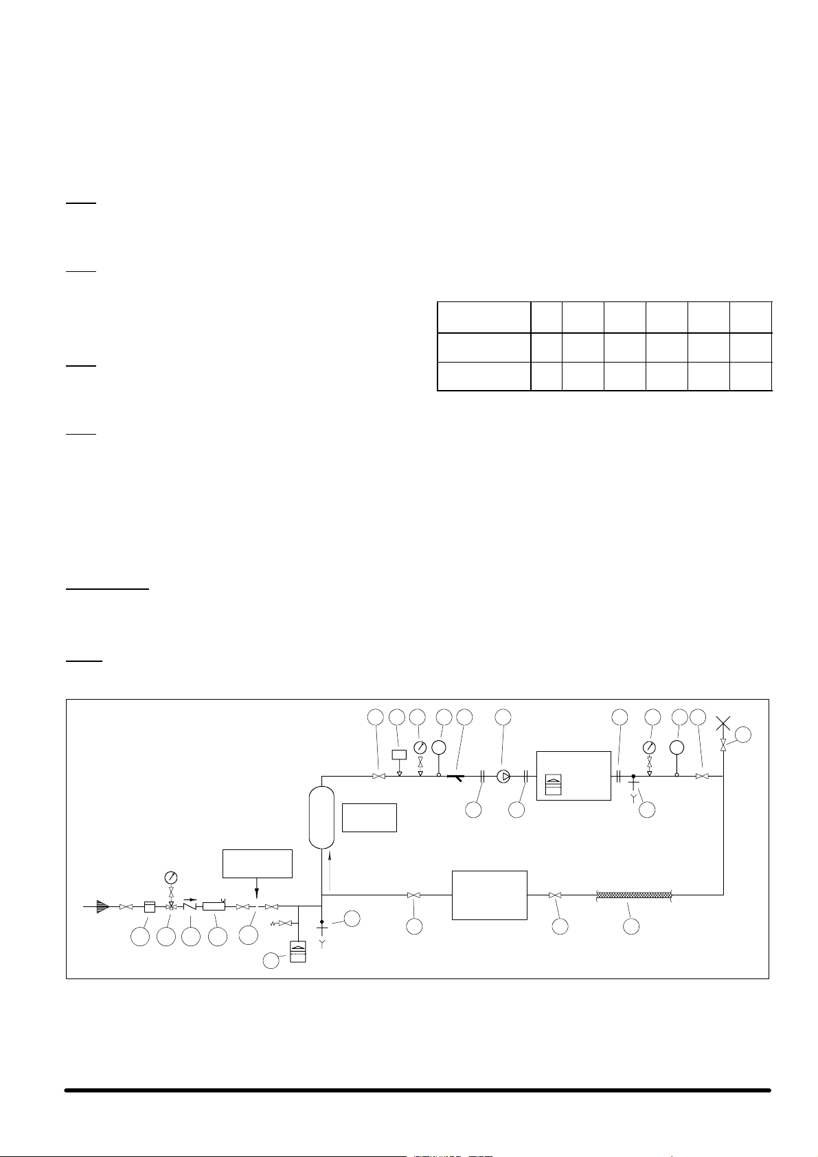
3.2.1 -- Hydraulic circuit construction (Fig. a)
The piping must be connected to the chiller. Construct a chilled
water circuit as described below, see Fig. a:
1) Place shut---off valves within the circuit to allow servicing;
2) Install a pump system suitable for the flow rate required at
a pressure head equal to the sum of all the pressure drops
(see project data).
Matrix R chillers can be equipped, upon request, with
pumps having performance as indicated in Tab. 8;
3) Install manometers at the chiller inlet/outlet;
4) Install thermometers at the chiller inlet/outlet;
5) Connect the pipes to the chiller by flexible joints to avoid
transmitting vibrations and to balance the thermal expansion; proceed in the same way even if the pump set is outside the chiller;
6) It is useful to include a water pressure switch to give an early
warning of low water pressure;
7) Place a mesh filter at the inlets of the pump and water chiller
(Can be supplied as an optional accessory --- Not fitted);
8) Install, at the highest points in the circuit, apparatus which
allows the bleeding of air and possibly the filling of glycol;
9) Place a drain valve at the lowest point in the circuit and immediately at the outlet of the water chiller;
10) Install a water filling set including the following:
a) filling water meter;
b) manometer;
c) non---return valve;
d) air separator;
e) removable supply tube, which must be disconnected
after each charge/top ---up;
2
11) For maximum protection ensure that all tubing exposed to
low outdoor temperatures is fitted with anti ---freeze heaters
and insulated using closed cell synthetic rubber (elastomer);
12) The circuit must include an expansion vessel (with safety
valve) of suitable capacity;
13) Connect the lines avoiding stresses on the machine inner
parts.
Note:
If the water chiller is complete with an expansion vessel (supplied as an option), check if the capacity is enough, and install
a second vessel in the circuit, if required (see par. 8.4).
Follow the indications in Fig. c for the correct sizing.
Note:
The whole circuit must contain a water volume suitable for the
capacity of the installed chiller. Check if the inertial capacity given by the sum of the hydraulic volume inside the machine (including the volume of the optional interna tank, if fitted) and the
system volume is sufficient, or possibly install a tank in the circuit.
Follow the indications in Fig. b for the correct sizing.
Note:
The hydraulic circuit must ensure a constant water supply to the
evaporator in every operating condition. Otherwise, the compressors may be damaged by repeated returns of liquid refrigerant on their suction.
Note:
The water flow switch is a compulsory safety component that
must be installed and correctly wired to the Matrix R chillers,
otherwise the guarantee will be invalidated.
It is installed, as standard, on units with the optional on --- board
pump set, and is available as a option for units without pumps
on board: in the latter case the flow switch, if not installed on the
machine, can be installed on the hydraulic circuit by the installer,
butitiscompulsorythatitiswiredtotheelectricpanelterminal
board, as indicated on the wiring diagram.
3.2.2 -- Addition of water and ethylene glycol
Very important:
Add water and ethylene glycol to the circuit with a % depending
on the minimum temperature of the outside air expected at the
installation site. Do not exceed the nominal operating pressure
of the circuit’s components.
Notes:
S To avoid stratification run the circulation pump for at least 30
minutes after adding any glycol.
S After adding water to the hydraulic circuit always discon-
nect the water supply coming from the sanitary supply;
this avoids the danger of glycol entering the sanitary water
system.
S After any topping --- up of the water check the concentration
and add glycol if necessary.
3.2.3 -- Water--gly col mixture
Water---glycol mixtures are used as the thermal carrier fluid in
very cold climates or with temperatures below zero degrees centigrade. Determine the ethylene glycol % which must be added
to the water, with the assistance of T ab. a.
Tab.a--Ethyleneglycoltobeaddedtowater(%in
weight of total mixture)
Ethylene glycol
(% in weight)
Freezing tempera-
(*)
ture, ûC
Mixture density at
(*)
20ûC
,kg/l
(*) Values are for Shell antifreeze 402. For different brands, check
manufacturer’s data.
For the chiller internal water volume refer to Tab. 1. If the optional
buffer tank is installed on the machine, add the tank hydraulic
volume.
ALWAYS CHARGE THE HYDRAULIC CIRCUIT WITH THE REQUIRED GLYCOL % NECESSARY FOR THE MINIMUM AMBIENT TEMPERATURE AT THE INSTALLATION SITE. FAILING
TO COMPLY WITH THIS INSTRUCTION SHALL INVALIDATE
THE UNIT WARRANTY.
0 10 20 30 40 50
0 --- 4 . 4 --- 9 . 9 --- 1 6 . 6 --- 2 5 . 2 --- 3 7 . 2
--- 1.017 1.033 1.048 1.064 1.080
3.3 --- Connection of the safety valve discharge
Safety valves are installed on the high pressure side of the refrigeration circuit(s): the discharge of these valves must be conveyed outside through a suitable pipe, having a diameter of at
least that of the valve outlet, without burdening the valve body.
Convey the discharge to areas where the jet cannot harm
people and the surrounding environment.
Fig. a --Ideal chilled water circuit
disconnect af-
ter charge
10e
10d10c10b10a
12
flow
9
Vpt
Ta n k
1 1327436
5
T T
CHILLER
5 5 9
USER
11
3
4
8
11
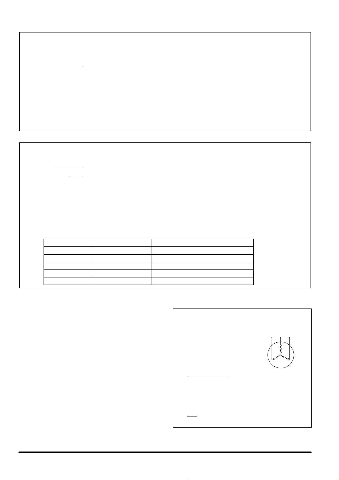
Fig. b --Inertia tank sizing
The total optimum hydraulic volume of the system where the Matrix R chiller is installed can be calculated by the
following formula:
43 x Rt
V =
where:
--- V=minimum required total water volume expressed in litres
--- Rt=refrigeration capacity expressed in kW
--- Xd=differential band set on the control and expressed in degrees centigrade
Please note that the sum of the hydraulic volume of the Matrix R chiller (Vm) plus the volume of the hydraulic circuit
connected to it (Vpc) must be greater than, or equal to the minimum required total water volume (V). If this condition is not satisfied, it is necessary to install an inertia tank (Vpt, as indicated in the Fig. a) with a volume at least
equal to the following value: Vpt=V ---Vm---Vpc
Fig. c --Sizing of the expansion vessel
The total volume of the expansion vessel is calculated with the following formula:
Xd
C x e
V =
1 --
Pi
Pf
where:
-- - C=quantity of water inside the system expressed in litres
-- - e=water expansion coefficient, with water at 10ûC as a reference
-- - Pi=absolute pressure of initial charging, equivalent to the vessel pre --- charge pressure (typical value
2.5 bara)
-- - Pf=absolute final tolerated pressure, lower than the operating pressure of the safety valve calibration
pressure (typical value 4.0 bara).
Use the values of the water expansion coefficient indicated in the table below:
H2OT[°C] Density [kg/m3] Expansion coefficient “e”
10 999.6 --- --- ---
20 997.9 0.0017
30 995.6 0.0040
40 992.2 0.0075
50 988.1 0.0116
3.4 --- Electrical connections
1) Before proceeding with the electrical connections, ensure
that:
S all electrical components are undamaged;
S allterminalscrewsaretight;
S the supply voltage and frequency are in accordance with
the rating (with tolerance in accordance with IEC 8--- 6
norms, March 1990)
S the allowed phase to phase variability is 3% maximum
(see Fig. d). Variability in excess of 3% invalidates the
guarantee.
2) Supply cable connections (see Tab. 5):
S Connect the cable to the supply terminals.
S Use appropriately sized 3--- pole cable. An earth wire
must also be connected.
S After having opened the passagein the framework (pre ---
punched knock ---outs) for the supply line entry, restore
the original degree of protection using suitable accessories for the wiring and junction boxes.
Fig. d --Example of calculating phase
to phase variability
1) The 400 V supply has
the following variability:
RS = 388 V
ST = 401 V
RT = 402 V
2) The average voltage is:
388 + 401 + 402
3
3) The maximum deviation from the average is:
402 --- 397 = 5 V
4) Thephasetophasevariabilityis:
5
x 100 = 1. 26 (acceptable)
397
= 397
RS T
4

Note:
The power supply should never be disconnected, except when
performing maintenance.
Operate (open) the main switch before carrying out any maintenance work on electrical components.
Note:
It is forbidden to work on the electrical components without
using insulating platforms, and in the presence of water or fog
or mist.
Note:
The supply to the externalpump assembly must be made before
starting the chiller and must be kept on as long as the chiller is
in use. Incorrect operation will cause the unit to lock ---out because of the internal protections (flow switch intervention).
Note:
The compressors are equipped with an electronic protectiondevice blocking their start if the phase sequence is not correct, or
stopping their operation if a thermal relay intervenes. This device
is essential for the integrity of the mechanical and electrical components of the compressors. Reset the standard functions by
isolating this device and removing the causes of the lock---out.
Note:
The chillers are equipped with their own microprocessor control
adjustment. The use of the remote ON ---OFF input (located in
the electric panel terminal board) as a system temperature control element is forbidden.
7) During the unit start---up an inlet water temperature
higher than 20ûC is allowed. Under standard operating
conditions check that the limits indicated in paragraph
2.1 are not exceeded.
8) Check the correct operation of the control and safety devices.
9) Check the outlet temperature of the chilled water (check if
the set--- point set on the controller is reached).
10) Check the compressor oil level.
11) With the compressor at full load, check there are no
bubbles visible in the frefrigerant sight glass. If there are any,
charge the unit according to par. 5.
4.3 --- Starting and stopping
ALWAYS ENSURE THAT THE COMPRESSOR OIL HAS BEEN
PREHEATED.
FOR BRIEF STOPPAGES MAINTAIN THE SUPPLY TO THE
CRANKCASE HEATER (IF ANY).
S Start the unit setting the Microprocessor switch ON.
S Stop the unit setting the Microprocessor switch OFF.
S In case of long stops, turn the machine off using the Micro-
processor switch OFF.
In this case the compressor crankcase heaters (if any) remain powered.
S For seasonal shutdown of the unit operate the main switch
locatedon the main electrical power supply. This will disconnect the compressor crankcase heaters.
4 --- S t a r t --- U p a n d O p e r a t i o n
4.1 --- Initial check
1) Check all water connections.
2) Open the shut---off valve on the liquid line.
3) Ensure that the intake pressure is higher than 4.0 bar; if this
is not the case, prolong pre --- heating of the compressor (if
possible) and check that the refrigerant shut --- off valve is
properly sealed, see Fig. 12, Fig. 13, Fig. 14, Fig. 15, Fig. 16
and Fig. 17.
4) Open all isolating valves and/or water ball valves.
5) In case of climates with temperatures below zero degrees C,
make sure the chilled water circuit is filled with the correct
concentration of water/glycol.
6) Bleed all air out of the chilled water circuit.
7) Verify the water flow rate and its direction.
8) Ensure that the thermal load is sufficient for start---up.
Caution:
The ambient air temperature probe must be positioned in the
shade and protected against the weather.
4 . 2 --- F i r s t s t a r t --- u p
(or after a long stop)
Operate as follows:
1) At least 8 hours before the start ---up, power the crank-
case heaters (if any, see point 4) by setting the main isolator switch ON. Make sure the auxiliary circuit has b een
powered and check the operation (a fault due to an incorrect procedure will invalidate the compressor guarantee).
2) Open the valves of the refrigeration circuit that had been
closed before the initial check.
3) Check the machinery supplying the thermal load connected
with the unit and start the system pump(s).
4) MAKE SURE THE COMPRESSOR OIL HAS BEEN HEATED
FOR AT LEAST 8 HOURS; start the unit only then. In the
units not equipped with crankcase heaters (Chillers for summer operation only, without modulating fan speed control),
the start must be carried out in the warm season only (external T > 15ûC), and thus oil pre---heating is not necessary.
5) Make sure the fans rotate in the correct direction (anticlockwise): check the electrical connections, if necessary .
6) Make sure the pumps rotate in the correct direction.
4.4 --- Chillers serving special plants
The units are capable of cooling a water ---glycol mixture to temperatures close to 0ûC without the need for significant modifications. In the case of modification, the set values of the safety and
control components must also be changed. This can be carried
out in the factory (at the time of testing) or at the time of installation, only by qualified and authorised personnel.
4 . 5 --- F r e e c o o l i n g
The “freecooling” is a system of pre ---cooling and/or cooling the
water/glycol mixture using ambient air when the latter is at a temperature below the return mixture temperature. If the outside
temperature is sufficiently low to dissipate the entire heat load,
the refrigeration compressors automatically switch off, and the
mixture’s temperature is controlled by the fan speed adjustment.
If the mixture temperature is too high for freecooling, the compressors will operate as long as necessary to ensure the correct
water/glycol mixture temperature.
4.6 --- Microprocessor control
Consult the ”Microface and Hiromatic” Service Manual.
5 --- R e f r i g e r a n t a n d O i l C h a r g e
All work on pipes or components of the refrigerating circuit under pressure must be exclusively carried out by qualified staff,
competent in such works.
5 . 1 --- R e f r i g e r a n t c h a r g e
WHILST REPAIRING THE REFRIGERATING CIRCUIT RECOVER ALL THE REFRIGERANT IN A CONTAINER: DO NOT
ALLOW IT TO ESCAPE. NEVER USE THE COMPRESSOR
FOR THE SYSTEM VACUUM (THIS INVALIDATES THE
WARRANTY).
S The unit is delivered charged according to the Tab. 2.
Warning for the refrigerant charge:
S Ensure there are no refrigerant leaks.
S Check the refrigerant type in the refrigeration circuit: a unit
originally charged by the manufacturer with R407C cannot
be charged with R22 and vice versa; possibly apply to the
Technical Support Department.
5
S Charge with the compressor in operation, connecting the
cylinder with the charge connector after the thermostatic expansion valve.
Flush the connection pipe between the cylinder and the
charging point; tighten the seal joint and then start charging
the unit. It is imperative that the cylinder is weighed both before and after the operation.
S For the units with R407C the refrigerant charge must be
made exclusively with liquid refrigerant.
S Charge the unit until the bubbles in the sight glass have dis-
appeared and the working conditions of the entire refrigeration circuit have returned to normal (sub---cooling and superheating within the limits indicated below).
S Measure the superheating as follows:
1) Detect the temperature on the suction line, close to the
bulb of the thermostatic expansion valve, using a contact
thermometer.
2) Connect a pressure gauge (by max. a 30 --- cm pipe) with
the Schraeder connection and read the corresponding
saturated evaporating temperature.
3) The superheating is the difference between the two
readings.
4) For the units with R407C refer to the pressure gauge
scale indicated with the initials D.P. (Dew Point)
S Verify that the superheating is 5ûC --- 8 ûC.
S Measure the sub---cooling as follows:
1) Detect the temperature on the liquid line using a contact
thermometer.
2) Connect a pressure gauge (by max. a 30 --- cm pipe) with
the Schraeder connection on the liquid line and read the
corresponding saturated condensing temperature.
3) The sub --- cooling is the difference between the two readings.
4) For the units with R407C refer to the pressure gauge
scale indicated with the initials B.P. (Bubble Point)
S Verify that at the condenser outlet, sub --- cooling is 3ûC ---
5ûC.
IT IS IMPORTANT TO CARRY OUT CHARGING CORRECTLY.
An excess of refrigerant causes an increase in sub --- cooling and
consequent operating difficulties in the hot season; a shortage
of charge generates an increase in superheating and possible
compressor stoppages. Whenever work is carried out on the
unit, ensure afterwards that the working conditions are correct,
checking sub---cooling and superheating.
5 . 2 --- O i l c h a r g e
Contact the TechnicalSupport Department for the specifications
of the oil to be used for topping up; the oil changes according to
thetypeofusedrefrigerant.
NEVER MIX DIFFERENT OILS TOGETHER. CLEAN THE PIPING COMPLETELY BEFORE CHANGING THE TYPE OF OIL
USED.
TOP ---UPS OF UP TO 20---30% OF THE TOTAL AMOUNT OF
OIL CONTAINED IN THE COMPRESSOR CRANKCASE ARE
PERMITTED; FOR LARGER PERCENTAGES CONTACT THE
TECHNICAL SUPPORT DEPARTMENT.
5.2.1 -- Procedure for oil topping--up
If there has been any loss of oil then this must be topped up as
follows:
1) T ake a clean, dry, transparent container (with volume calibrations) and fill it with at least twice the amount of oil required.
2) Isolate the compressor by closing the cock on the liquid line.
3) Connect to the fittings on the compressor body (Schraeder
valves) and empty it of refrigerant until atmospheric pressure (1 bar) is reached.
4) Using a pipe, connect the oil containerto the oil service fitting
on the lower part of the compressor.
5) Open the oil service cock, lifting the container, so that the oil
flows by gravity.
6) Charge the required quantity of oil (make sure the tube always remains below the oil level in the container).
7) Stop the oil flow by closing the oil service fitting, open the
shut---off cock on the refrigerating circuit and restore the
drained refrigerant charge.
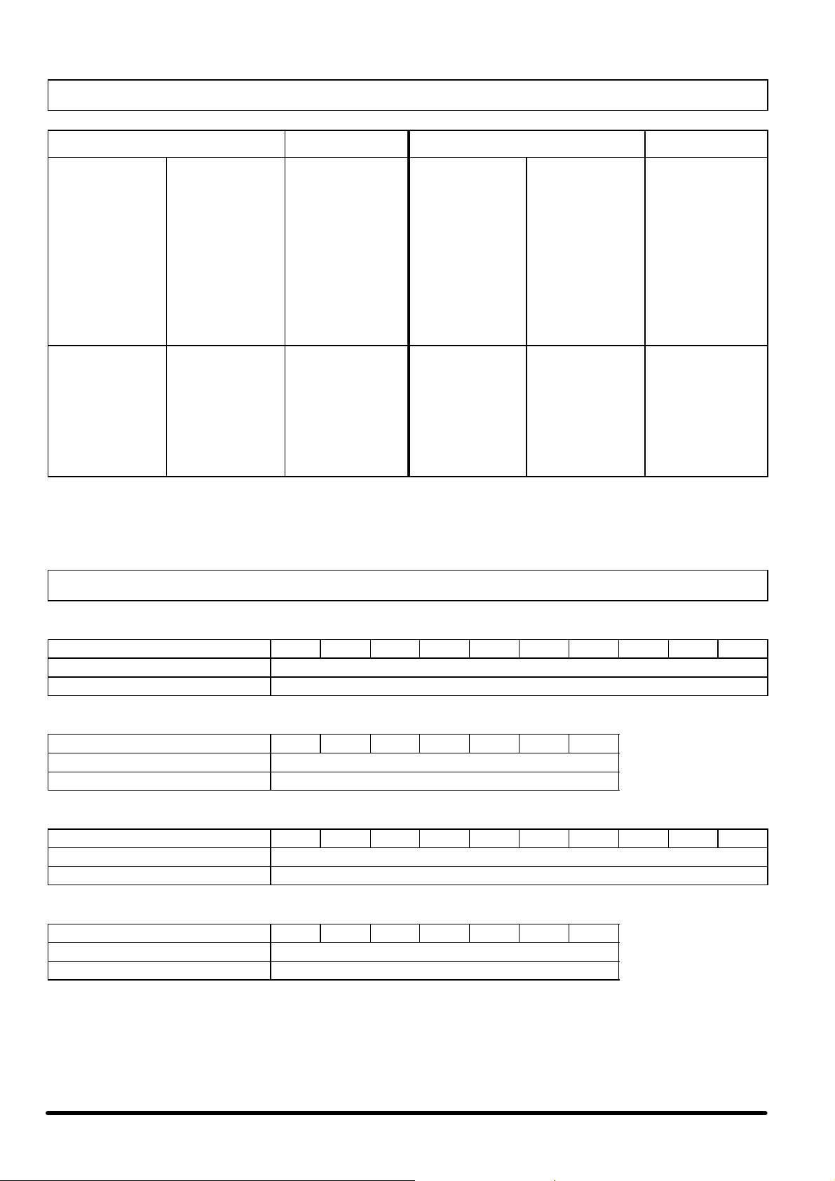
6 --- Safety Devices Settings
The water chiller has already been tested and set up by the manufacturer. The following setting values are suggested in the field.
COMPONENT SETTING NOTES
diff.set
Operation with R407C/R22
(standard factory setting):
Low pressure switch (LP)
High pressure switch (HP)
START : 3.6 bar
DIFF. : 0.8 bar
STOP : 2.8 bar
Operation with R407C/R22
(standard factory setting):
STOP : 26 bar
START : 20 bar
DIFF. : 6 bar (fixed)
The settings for the safety valves installed on the machine are indicated below:
MODELS SETTINGS SAFETY VALVE
004 ---204 --- 206 --- 207 --- 008 28 bar
006 ---007 --- 011 --- 014 --- 016
017 ---020 --- 023 --- 025 --- 028 ---030 --- 032
29 bar
reset
0.2
5
bar
HP side
1.5
0.5
bar
6

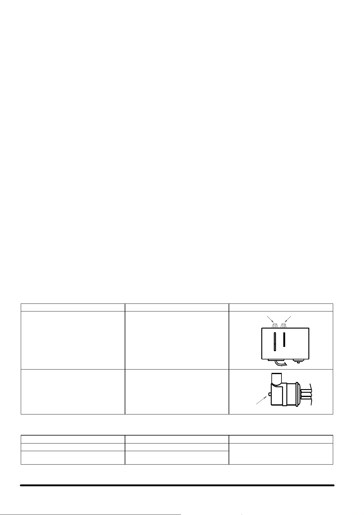
6.1 --- Setting thermostatic expansion
valve
THIS OPERATION MUST BE PERFORMED BY AN EXPERIENCED REFRIGERATION TECHNICIAN.
Before beginning this adjustment be sure that the refrigerant
charge is correct, checking the the sub --- cooling (3ûC---5ûC, as
specified in par. 5.1).
The valve has already been factory--- set and should be reset
when the superheating is not between 5ûC --- 8 ûC, as follows:
1) Important:
Ensure that the instructions in par.5.1 have been carried out.
2) Allow the compressor to operate for 15 mins.
3) Measure the superheating as follows:
a) Connect a manometer to the Schraeder connection lo-
cated on the evaporator outlet tube, and read the manometric temperature on the scale for the refrigerant used
(for the units with R407C refer to the pressure gauge
scale indicated with the initials D.P. = Dew Point).
b) Using a contact thermometer, measure the temperature
on the tube coming out of the evaporator, next to the
socket used for the manometer.
7 --- Maintenance
The Maintenance Programme below must be carried out by a
qualified technician, preferably working under a maintenance
contract.
Before any intervention on the unit or accessing the inner components (removing the outer panels), always ensure the machine is switched off. If the panels are removed (fans compartment) wait for the fan(s) to come to a complete stop before
accessing the compartment; if the front panels are removed (on
mod. 004 ---016) or the front lower panels (on mod. 017 --- 032),
pay special attention when working near the compressor upper
part and the discharge line: they are very hot; possibly wait for
them to cool. Be very careful when operating close to the finned
coils, as the fins are very sharp. Do not remove the fan protection
grille before electrically isolating the whole machine. Do not insert foreign matter through the fan protection grille. After the
maintenance interventions, always close the unit with the suitable panels, fastened by the tightening system.
c) The superheating is the difference between the two
readings (b ---a).
4) The superheating must be 5ûC---8ûC; if not, set the expan-
sion valve as follows:
a) Remove the protective cover;
b) Turn the adjustment screw to return to the optimum val-
ues, tightening it in a clockwise direction to increase the
superheating, or slackening it to reduce the superheat-
ing.
c) Wait about 10 minutes;
d) Measure the superheating and repeat the operation if
necessary.
N.B:
If the superheating is too low, there is a risk of poor lubrication
and consequent breakage of the compressor as a result of pressure shock.
If the superheating is too high the output of the system is limited
and the compressor overheats.
7.1 --- Spare parts
The use of original spare parts is recommended.
When placing an order refer to the ”Component List” enclosed
with the machine and quote the unit model no. and serial no.
7.2 --- Dismantling the unit
The machine has been designed and built to ensure continuous
operation.
The working life of some of the main components, such as the
fans and the compressors, depends on the maintenance that
they receive.
If the unit has to be dismantled, the job must be done by skilled
refrigeration technicians.
The refrigerant and the lubricating oil in the circuit must be disposedofinconformitywiththelawsinforceinyourcountry.
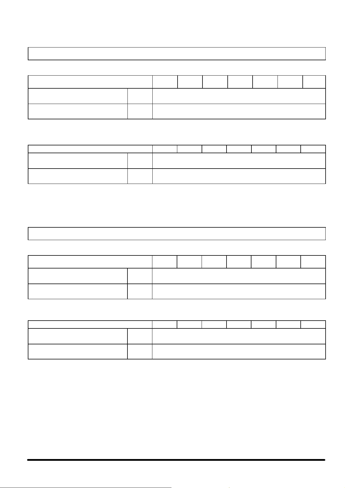
Maintenance programme -- Monthly check
S Check that the fan motor rotates freely without any abnormal noise, and ensure that the
FANS
CONDENSER AND AIR FILTER
CONTROL S Check that the control equipment, LEDs and display are operating correctly.
ELECTRICAL CIRCUIT
REFRIGERATION CIRCUIT
CHILLED WATER CIRCUIT
bearings are not running hot.
S Also check the current absorption.
S Check the conditions of the filters (if they are supplied); if necessary clean them (including
the electrical panel ventilation filter).
S Check the condenser coils and clean if necessary with compressed air or soft brushes.
S Check the electrical supply on all phases.
S Ensure that all electrical connections are tight.
S Check the condensing and the evaporating pressures (to be done by a refrigeration techni-
cian).
S Check the compressor’s current absorption, the delivery temperature and possible unusual
noises.
S Check the refrigerant charge by means of the sight glass.
S Check that the safety devices operate correctly.
S Check the correct operation of the thermostatic valve (superheating between 5ûC --- 8ûC).
S Check that the oil level indicated by the compressor sight glass is higher than the min. value.
S Ensure that there are no water leaks.
S Bleed any air out of the hydraulic circuit using the bleed valves.
S Verify that the water flow rate is correct.
S Check the inlet --- outlet liquid temperature and pressure.
S Check the correct operation of the three---way valve (Versions with free---cooling only).
S Check if the system is charged with the specified glycol percentage and that no ice has
formed in the hydraulic circuit.
S Check the evaporator cleanliness.
7

8 --- O p t i o n s a n d A c c e s s o r i e s
8 . 1 --- P u m p s e t
On mod. 004 --- 016 the centrifugal pump units are direct driven,
with close-- -coupled motors and a single shaft; the induction motor has 2 poles with IP 54 protection and class F insulation.
The materials used for the pump main components are:
S Pump body in plastic material PA 6.6 (cast iron in all high
pressure freecooling versions and on model 016 in the Chiller high head pressure version and Superchiller standard
head pressure version);
S Impeller in in plastic material PPO (stainless steel in all high
pressure freecooling versions and on model 016 in the Chiller high head pressure version and Superchiller standard
head pressure version);
S Stainless steel shaft;
S Graphite impregnated ceramic mechanical seal (EPDM in
all high pressure freecooling versions and on model 016 in
the Chiller high head pressure version and Superchiller
standard head pressure version), suitable for the use of mixtures containing ethylene glycol.
The pump units have been chosen and sized to operate within
specific limits, namely:
S Water / ethylene glycol mixtures up to 65% / 35% by weight;
S Temperatures of the standard pumped fluid not lower than
4°C.
The hydraulic circuitincludes,for each pump, a suctionshut---off
valve and a delivery check valve if two pumps are installed, or
suction and delivery shut---off valves if a single pump is installed.
On mod. 017 --- 032 the centrifugal pump units are direct driven,
with close-- -coupled motors and a single shaft; the induction motor has 2 poles with IP 55 protection and class F insulation.
Pump casings and impellers are in cast iron EN -- -GJL 200, shafts
are in stainless steel, the shaft seal is a unbalanced, mechanical
shaft seal with dimensions according to DIN 24 960 and assembly length according to EN 12 756, brass neck ring permits ideal
conditions for the use of water mixtures containing ethylene glycol. The pump housing, the motor stool and the motor stator
housing are electrocoated.
The pump units have been chosen and sized to operate within
specific limits, namely:
S Water / ethylene glycol mixtures up to 65% / 35% by weight;
S Temperatures of the standard pumped fluid not lower than
4°C.
The motor stool forms connection between the pump housing
and the motor, and is equipped with a manual air vent screw for
venting of the pump housing and the shaft seal chamber. It is
very important to carry out this operation as the circulation of liquid through the duct of the air vent screw ensures lubrication and
cooling of the shaft seal.
Between the outlets of the two chambers and the discharge
flange, twin --- head pumps have a non --- return flap valve in
EPDM rubber. The flap is opened by the flow of the pumped liquid and cuts off the port of the idle pump chamber.
In the electrical panel there are, for all the models of pumps, automatic circuit breakers for each pump; the microprocessor control manages the operating rotation between the two pumps and
start---up of the stand ---by pump if the primary pump fails.
For the technical features of the pumps and the hydraulic schematic see Tab. 8, Fig. 18, Fig. 19, Fig. 20, Fig. 21, Fig. 21 and
Fig. 22.
8.2 --- Water chiller with partial heat
recovery (20%)
This option enables the recovery of up to 20% of the heat normally rejected by the condensers. The system does not require any
adjustment and is made up of plate heat exchangers installed
on each circuit before the condenser. The exchangers are pro-
tected by a suitable anti --- frost heater that operates when the system is stopped. It is recommended that a safety valve be
installedin the hydraulic circuit to avoid hazards due to overpressures, if there is no water flow through the recuperator.
The water temperature at the recuperator inlet (in stable operating conditions) must be in the range of 25ûC --- 45 ûC, with an outlet differential of between 3.5ûC --- 8 ûC.
8.3 --- Water chiller with total heat recovery
(100%)
All heat discharged by the unit to the condenser is recovered.
The system includes an additional refrigerating circuit made up
of a three --- way solenoid valve, supplying --- in case of hot water
demand --- a plate exchanger, usually by --- passed and sized so
as to discharge all condensing heat (also installed before the
finned air condenser in series with it); a check valve, a liquid receiver at the exit of the finned air condenser working as storage
for the needed additional refrigerant charge (see refrigerating
scheme). The recuperator is insulated with closed cell polyurethane and is equipped with heaters activated when the recuperator is deactivated to prevent frost in winter with the system
stopped or not perfectly drained.
The operation in total recovery mode is enabled by an external
contact. The Microface control will simultaneously suit the fan
speed changing the fan speed setpoint differently from the standard operation without recovery (practically slowing the fans
down till they switch off); anyway , the operation in recovery
mode is enabled also without load at the users. Indeed, if the users do not demand heat, the water flowing to the condenser
reaches a temperature that does not enable the total condensation of the compressed gas, and the remaining portion of the
phase change can thus take place in finned coil without interrupting the recovery process through the intervention of the machine safety devices.
If the plate exchanger is supplied with too cold water, or if the system is not preset by the installation technician with a three or
two---way proportional adjustment valve for the exchanger bypass (indispensable for cold starts, see following “Recommended hydraulic circuit” ), the condensing pressure tends to
decrease too much; a prolonged condition of low condensing
temperature below the safety threshold leads the Microface microprocessor control to disable the heat recovery, protecting the
system from any possible malfunctioning.
Fig. e -- Recommended hydraulic circuit
Heat recovery
users
Heat recovery
exchanger
8.4 --- Hydraulic circuit accessories
Made up of an expansion vessel (pre --- charged at 1.5 bar, max.
operating pressure 10 bar) and a safety valve, set at 5 bar. Their
position in the hydraulic circuit is illustrated in Fig. 18, Fig. 19,
Fig. 20, Fig. 21, Fig. 21 and Fig. 22.
S Expansion vessel volume:
-- - 8 litres for all 004 ---016 units,
-- - 12 litres for all 017 ---032 units.
It is recommended that the total required expansion vessel capacity is always checked, depending on the unit’s internal hydraulicvolume(withthevolumeofthebuffertank,ifinstalled),
the user circuit volume, the glycol percentage in the mixture, and
the expected maximum temperature variation of the mixture.
The water flow switch is a compulsory device protecting the unit.
It is installed, as standard, on units with the optional on --- board
pump set, and is available as a option for units without pumps
8

on board: in the latter case the flow switch, if not installed on the
machine, must be installed on the hydraulic circuit by the installer and wired to the electric panel terminal board, as indicated on
the wiring diagram.
8.5--- Waterchillerwithinertiatank
The machine can be supplied complete with a buffer tank; it performs the inertial stabilizer function, for better compressor operation, summed up in the following two points:
S it reduces the frequency of the compressor peaks, which is
higher the lower the system thermal inertia, improving their
performance;
S it naturally eliminates the operational problems caused by
sudden load variations (shown by variations of the chilled
water temperature).
The buffer tank is supplied insulated, with a drain valve, vent
valve and connection for immersion electric heaters; maximum
operating pressure 6 bar.
Builtincarbonsteelandcoatedwithanti---condensationinsulation. It can be installed in all MATRIX R 004 --- 016 versions inside
the coil compartment, while on mod. 017 - --032 it is installed inside a cabinet which can be supplied either already connected
to the unit (mechanically and hydraulically jointed to it) or loose
(completely separate from the unit).
Mod. 004 ---006 --- 007 technical data
S Internal volume: 200 litres
S Net weight: 110 kg
S Working weight: 310 kg
Mod. 008 ---011 --- 014 ---016 technical data
S Internal volume: 400 litres
S Net weight: 140 kg
S Working weight: 540 kg
Mod. 204 ---206 --- 207 technical data
S Internal volume: 160 litres
S Net weight: 100 kg
S Working weight: 260 kg
Mod. 017 ---032 technical data
S Internal volume: 1000 litres
S Net weight: 400 kg
S Working weight: 1400 kg
9
Tab. 1 --- Internal hydraulic volume
Model Unit volume
004 8 004 37
006 9 006 38
007 14 007 75
204 10 204 39
CRH
CRH 025 45 SRH 025 158
(*) Add the tank’s volume for the units with optional buffer tank
206 10
207 18
008 24 008 97
011 27 011 101
014 38 014 146
016 46 016 156
017 37 017 129
020 37 020 129
023 45 023 158
028 51 028 186
030 60 030 195
032 60 032 195
(*)
[l] Model Unit volume
SRH
206 40
207 79
(*)
[l]
Tab. 2 --- R 407C refrigerant and oil charge
CRH 004--016
Models 004 006 007 204 206 207 008 011 014 016
Refrigerant charge (each circuit) [kg] 12.6 7.5 13.9 7.7 23.7 12.9 12.9 14.5 19.9 20.8
Oil charge (each circuit) [lt] 6.2 8.0 8.0 3.25 3.25 3.3 6.2 8.0 8.0 8.0
CRH 017--032
Models 017 020 023 025 028 030 032
Refrigerant charge (each circuit) [kg] 21.0 21.6 30.7 30.8 36.8 39.4 39.5
Oil charge (each circuit) [lt] 12.4 14.2 16.0 16.0 16.0 16.0 16.0
SRH 004--016
Models 004 006 007 204 206 207 008 011 014 016
Refrigerant charge (each circuit) [kg] 12.6 7.5 13.9 7.7 23.7 12.9 12.9 14.5 19.9 20.8
Oil charge (each circuit) [lt] 6.2 8.0 8.0 3.25 3.25 3.3 6.2 8.0 8.0 8.0
SRH 017--032
Models: 017 020 023 025 028 030 032
Refrigerant charge (each circuit) [kg] 21.0 21.6 30.7 30.8 36.8 39.4 39.5
Oil charge (each circuit) [lt] 12.4 14.2 16.0 16.0 16.0 16.0 16.0
10
Ta b . 3 --- CR H / S R H 0 0 4 --- 0 3 2 --- P a r t i a l h e a t r e c o v e r y ( 2 0 % )
CRH/SRH 004--016
Model
Heating capacity
Water flow
Water pressure drop
Water connections
Working conditions: outdoor temperature 35ûC, water inlet/outlet 12/7ûC (Chiller versions), glycol mixture 30% inlet/outlet 15/10ûC (SuperChiller versions).
Heat recovery conditions: water inlet/outlet 40/45ûC.
kW
l/s
kPa
B S P --- T
004
204
10,8 14,8 18,2 21,6 29,6 36,4 44,3
0,516 0,707 0,870 1,032 1,414 1,739 2,117
8 11 14 8 11 14 21
1” 1” 1” 11/4” 11/4” 11/4” 11/4”
CRH/SRH 017--032
Model 017 020 023 025 028 030 032
Heating capacity
Water flow
Water pressure drop
Water connections
Working conditions: outdoor temperature 35ûC, water inlet/outlet 12/7ûC (Chiller versions), glycol mixture 30% inlet/outlet 15/10ûC (SuperChiller versions).
Heat recovery conditions: water inlet/outlet 40/45ûC.
kW
l/s
kPa
B S P --- T
40 48 56 62 68 79 86
1.91 2.29 2.68 2.96 3.25 3.77 4.11
15 20 16 19 16 17 20
006
206
007
207
008 011 014 016
2”
Tab. 4 --- CRH/SRH 004 ---032 --- Total heat recovery (100%)
CRH/SRH 004--016
Model
Heating capacity
Water flow
Water pressure drop
Water connections
Working conditions: water inlet/outlet 12/7ûC (Chiller versions). Heat recovery conditions: water inlet/outlet 40/45ûC.
kW
l/s
kPa
B S P --- T
004
204
53 74 91 105 144 177 223
2,53 3,54 4,35 5,02 6,88 8,46 10,65
60 70 80 60 70 80 90
2” 2” 2” 21/2” 21/2” 21/2” 21/2”
CRH/SRH 017--032
Model 017 020 023 025 028 030 032
Heating capacity
Water flow
Water pressure drop
Water connections
Working conditions: water inlet/outlet 12/7ûC (Chiller versions). Heat recovery conditions: water inlet/outlet 40/45ûC.
kW
l/s
kPa
B S P --- T
212 238 290 320 357 412 453
10.13 11.37 13.86 15.29 17.06 19.68 21.64
52 65 71 82 83 85 99
006
206
007
207
DN 80 --- 3”
008 011 014 016
11
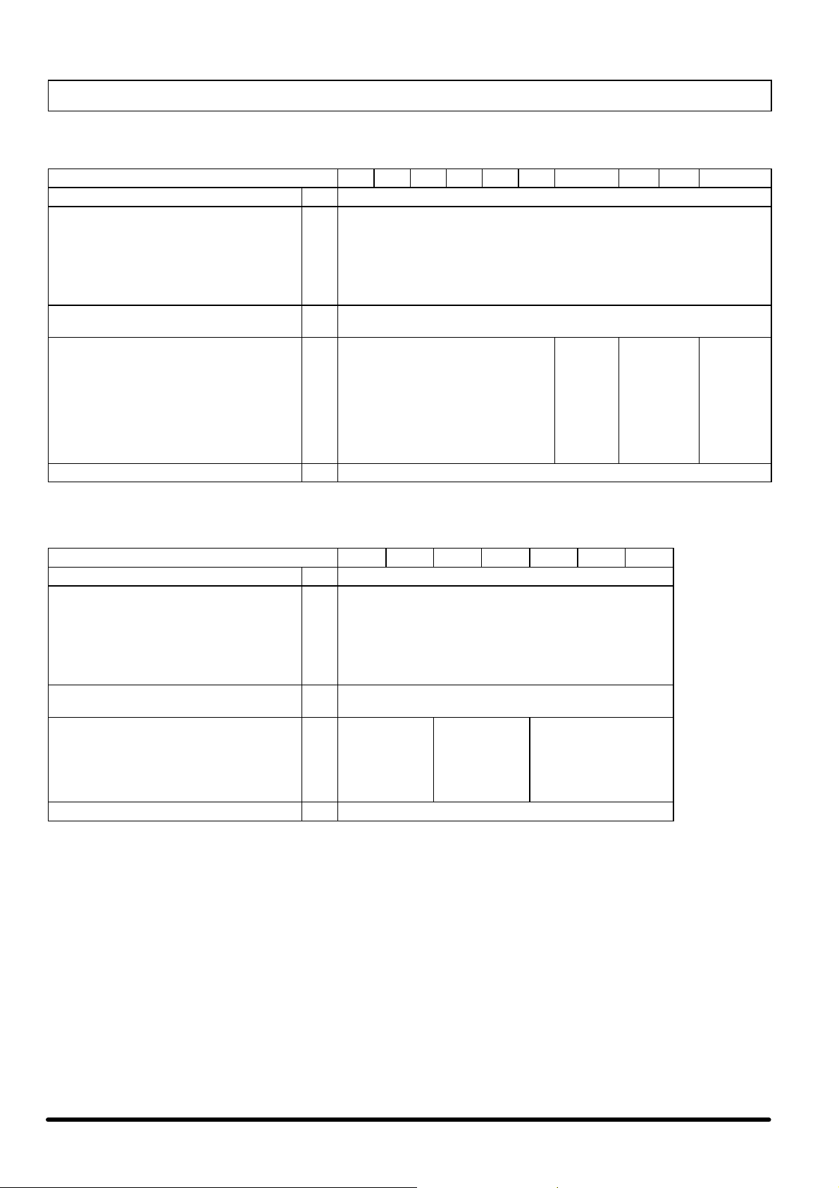
Tab. 5 --- Electrical characteristics
CRH 004--016 -- R 407C
Size 004 204 006 206 007 207 008 011 014 016
Power supply --- 400 V / 3 Ph / 50 Hz
(1)
OA
FLA
LRA
Compressors power input
Compressors nominal current
(1)
(1)
Compressor max. current
Fans power input
Fans max. power input
Fans max. current
SHC std. head pressure pump model (Opt.)
Std. head pressure pump motor nom. power
Std. head pressure pump motor max. power
Std. head pressure pump max. current
SHC high head pressure pump model (Opt.)
FHE high head pressure pump model (Opt.)
High head pressure pump motor nom. power
High head pressure pump motor max. power
High h ead pressure pump max. current
Electrical cable section (min.) mm216 16 25 25 35 35 35 50 70 95
(1) Outdoor air temperature 35ûC ; water inlet/outlet temperature 12/7ûC.
Nominal air flow and 50 Pa available air static pressure.
A
A
A
kW
A
A
kW
kW
A
--kW
kW
A
---
--kW
kW
A
31
43
183
13.2
23
35
2.9
32
46
125
13.2
24
19
2.9
40
58
223
19.3
32
50
3.3
12 --- 129
0.75
1.08
1.85
12 --- 136
---
1.1
1.44
2.67
42
66
167
19.0
34
29
3.3
48
77
278
24.1
40
69
3.1
50
72
185
24.6
42
32
3.1
4.9
8.2
12 --- 136
62
86
226
26.3
46
35
5.8
1.1
1.44
2.67
20---128
---
1.5
1.92
3.90
80
116
281
38.6
64
50
6.8
20 --- 128
1.5
1.92
3.90
20 --- 134
1.85
2.45
4.61
99
163
364
43.6
74
69
10.1
20---134
---
40---160/40
123
169
417
59.4
98
72
10.2
1.85
2.45
4.61
---
4.0
4.0
8.50
CRH 017--032 -- R 407C
Size 017 020 023 025 028 030 032
Power supply --- 400 V / 3 Ph / 50 Hz
(1)
OA
FLA
LRA
Compressors power input
Compressors nominal current
(1)
(1)
Compressor max. current
Fans power input
Fans max. power input
Fans max. current
SHC std. head pressure pump model (Opt.)
Std. head pressure pump motor power
Std. head pressure pump max. current
High head pressure pump model (Opt.)
High head pressure pump motor power
High h ead pressure pump max. current
Electrical cable section (min.) mm
(1) Outdoor air temperature 35ûC ; water inlet/outlet temperature 12/7ûC.
Nominal air flow and 50 Pa available air static pressure.
A
A
A
kW
A
A
kW
kW
A
---
kW
A
---
kW
A
125
165
305
57.3
100
35
9.7
135
195
360
64.9
110
50
9.7
163
233
398
77.7
130
50
13.1
183
271
472
90.1
150
69
13.1
4.9
8.2
65 --- 190/2
2.2
4.45
65 --- 260/2
4.0
8.00
2
70 95 120 150 185 185 185
65 --- 230/2
3.0
5.95
65 --- 260/2
4.0
8.00
199
317
518
94.5
158
69
16.5
225
323
571
111.7
184
72
16.5
65 --- 260/2
4.0
8.00
65 --- 340/2
5.5
11.20
245
329
577
124.8
204
72
18.1
12
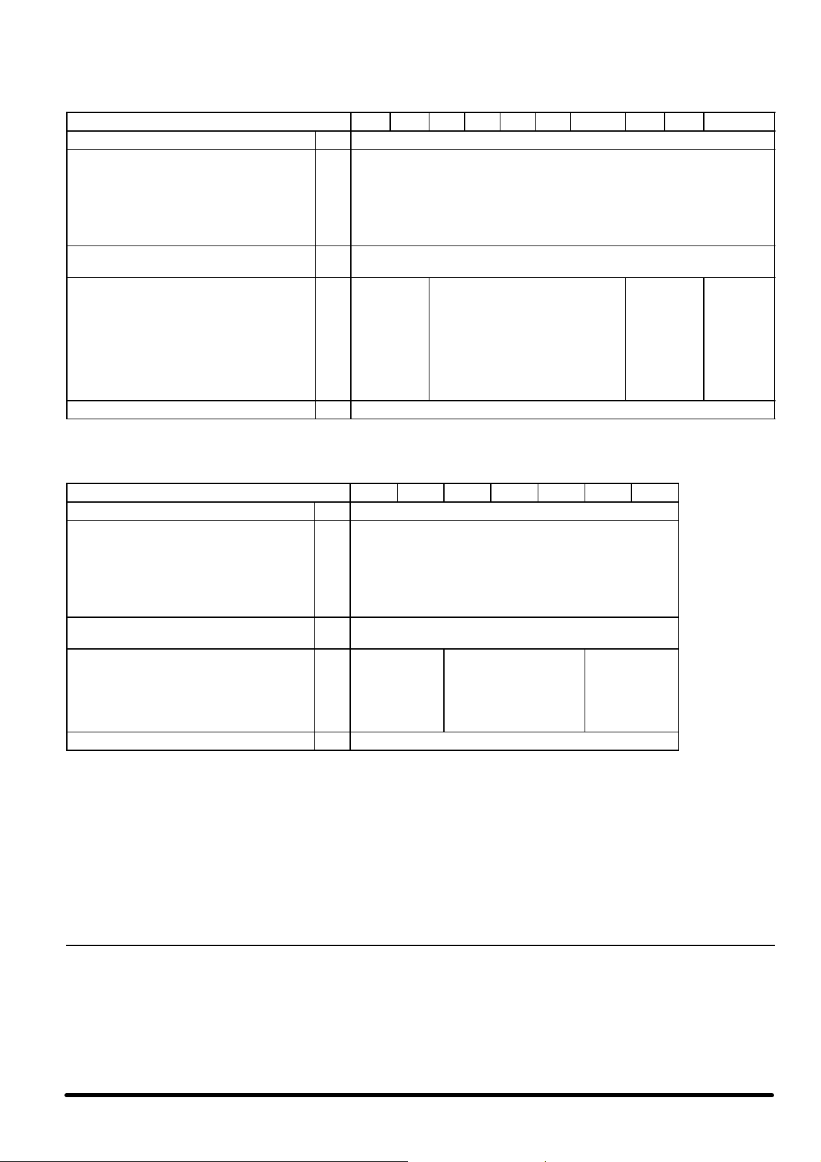
SRH 004--016 -- R 407C
Size 004 204 006 206 007 207 008 011 014 016
Power supply --- 400 V / 3 Ph / 50 Hz
(1)
OA
FLA
LRA
Compressors power input
Compressors nominal current
(1)
(1)
Compressor max. current
Fans power input
Fans max. power input
Fans max. current
SHC std. head pressure pump model (Opt.)
FHE std. head pressure pump model (Opt.)
Std. head pressure pump motor nom. power
Std. head pressure pump motor max. power
Std. head pressure pump max. current
SHC high head pressure pump model (Opt.)
High head pressure pump motor nom. power
High head pressure pump motor max. power
High h ead pressure pump max. current
kW
kW
kW
kW
kW
kW
A
A
A
A
A
A
---
---
A
---
A
32
43
183
13.4
24
35
3.2
12 --- 136
---
1.1
1.44
2.67
32---160/30
3.0
6.50
32
46
125
13.4
24
19
3.2
41
58
223
19.8
33
50
3.8
42
66
167
19.4
34
29
3.8
49
50
77
72
278
185
24.8
25.0
41
42
69
32
3.3
3.3
20 --- 128
---
1.5
1.92
3.90
32 --- 160/30
3.0
6.50
4.9
8.2
64
86
226
26.7
48
35
6.5
82
116
281
39.6
66
50
7.6
20 --- 134
---
1.85
2.45
4.61
40---160/40
4.0
8.50
101
163
364
44.5
76
69
11.4
40---160/40
40---200/75
Electrical cable section (min.) mm216 16 25 25 35 35 35 50 70 95
(1) Outdoor air temperature 35ûC; 30% glycol water mixture; water inlet/outlet temperature 15/10ûC.
Nominal air flow and 50 Pa available air static pressure.
SRH 017--032 -- R 407C
Size 017 020 023 025 028 030 032
Power supply --- 400 V / 3 Ph / 50 Hz
(1)
OA
FLA
LRA
Compressors power input
Compressors nominal current
(1)
(1)
Compressor max. current
Fans power input
Fans max. power input
Fans max. current
Std. head pressure pump model (Opt.)
Std. head pressure pump motor power
Std. head pressure pump max. current
High head pressure pump model (Opt.)
High head pressure pump motor power
High h ead pressure pump max. current
Electrical cable section (min.) mm
(1) Outdoor air temperature 35ûC; 30% glycol water mixture; water inlet/outlet temperature 15/10ûC.
Nominal air flow and 50 Pa available air static pressure.
kW
kW
kW
kW
kW
A
127
A
165
A
305
58.5
A
102
A
35
10.8
137
195
360
66.5
112
50
10.8
165
233
398
79.7
132
50
14.6
185
271
472
92.5
152
69
14.6
203
317
518
96.9
162
69
18.3
4.9
A
---
65 --- 260/2
4.0
A
---
8.00
65 --- 340/2
5.5
A
2
11.20
70 95 120 150 185 185 185
8.2
65 --- 340/2
5.5
11.20
65 --- 410/2
7.5
15.20
229
323
571
114.8
188
72
18.3
65 --- 410/2
7.5
15.20
65 --- 460/2
11.0
21.40
249
329
577
128.1
208
72
20.3
125
169
417
60.8
100
72
11.4
---
4.0
4.0
8.50
7.5
15.50
•
Nominal power supply = 400 V; 3 Ph; 50 Hz
•
Nominal power supply tolerance = 400 V ±10 %
•
Max. voltage unbalance = 3 %
•
The cables have to be sized in compliance with local standards and according to the type and characteristics of installation. Suggested cables sectionare
referred to PVC insulation with a max. working temperature of 70 ûC and an ambient temperature of 30 ûC.
13
 Loading...