

Page 1

SGH Steam
Generating Humidifier
Installation and
Operation Guide
IMPORTANT: Read and save this guide for future
reference. This guide to be left with equipment owner.
SL-14050 Form # 99-428 Rev. 1 / 150-1633 Rev. A
Page 2

Table Of Contents
INSTALLATION 1
RECEIVING & UNPACKING EQUIPMENT ................................1
PRE-INSTALLATION CHECKPOINT ...................................1
BASIC HUMIDIFIER CONFIGURATION..................................1
LOCATION & MOUNTING .........................................1
HUMIDIFIERS .............................................1
BLOWER PACKS............................................2
STEAM DISTRIBUTORS ........................................3
PLUMBING.................................................5
WATER SUPPLY LINE .........................................5
DRAIN LINE...............................................6
STEAM LINE ..............................................6
ACCESSORIES - FILL CUP EXTENSION KIT(S) ...........................8
CONDENSATE RETURN LINE.....................................8
ELECTRICAL................................................9
PRIMARY VOLTAGE SUPPLY WIRING TO HUMIDIFIER.......................9
PRIMARY VOLTAGE SUPPLY WIRING FROM HUMIDIFIER(S) TO BLOWER PACKS .......9
LOW VOLTAGE CONTROL WIRING..................................9
On-OffControls ...........................................9
CONTROL INSTALLATION ......................................10
OPTIONAL MODULATION (CONTINUOUS CONTROLS) ......................10
OPTIONAL MODULATION (CONTINUOUS CONTROL) PACKAGES BY LIEBERT.........11
OPERATION 11
INTRODUCTION .............................................11
SGH OPERATION ............................................11
END OF CYLINDER LIFE .......................................11
MANUAL CAPACITY ADJUSTMENT .................................11
On/Off Controls...........................................11
Modulation Control .........................................12
OTHER POTENTIOMETERS .....................................12
DETECTING WATER SUPPLY DEFICIENCY ............................12
REMOTE INDICATION ........................................12
DOUBLE UNIT OPERATION .....................................12
BLOWER PACK OPERATION ....................................12
Page 3
INSTALLATION
pply
3. Report any discrepancy immediately.
RECEIVING & UNPACKING EQUIPMENT
1. Check packing slip to ensure ALL material has
been delivered.
2. All material shortages are to be reported to
Liebert within 48 hours from receipt of goods.
Liebert assumes no responsibility for any
material shortages beyond this period.
3. Inspect shipping boxes for damage and note
on shipping waybill accordingly.
4. After unpacking, inspect equipment for
damage and if damage is found, notify the
shipper promptly.
5. All Liebert products are shipped on an F.O.B.
factory basis. Any and all damage, breakage
or loss claims are to be made directly to the
shipping company.
PRE-INSTALLATION CHECKPOINT
1. Ensure that available voltage and phase
corresponds with humidifier voltage and phase
as indicated on humidifier’s nameplate label
(see Figure #1).
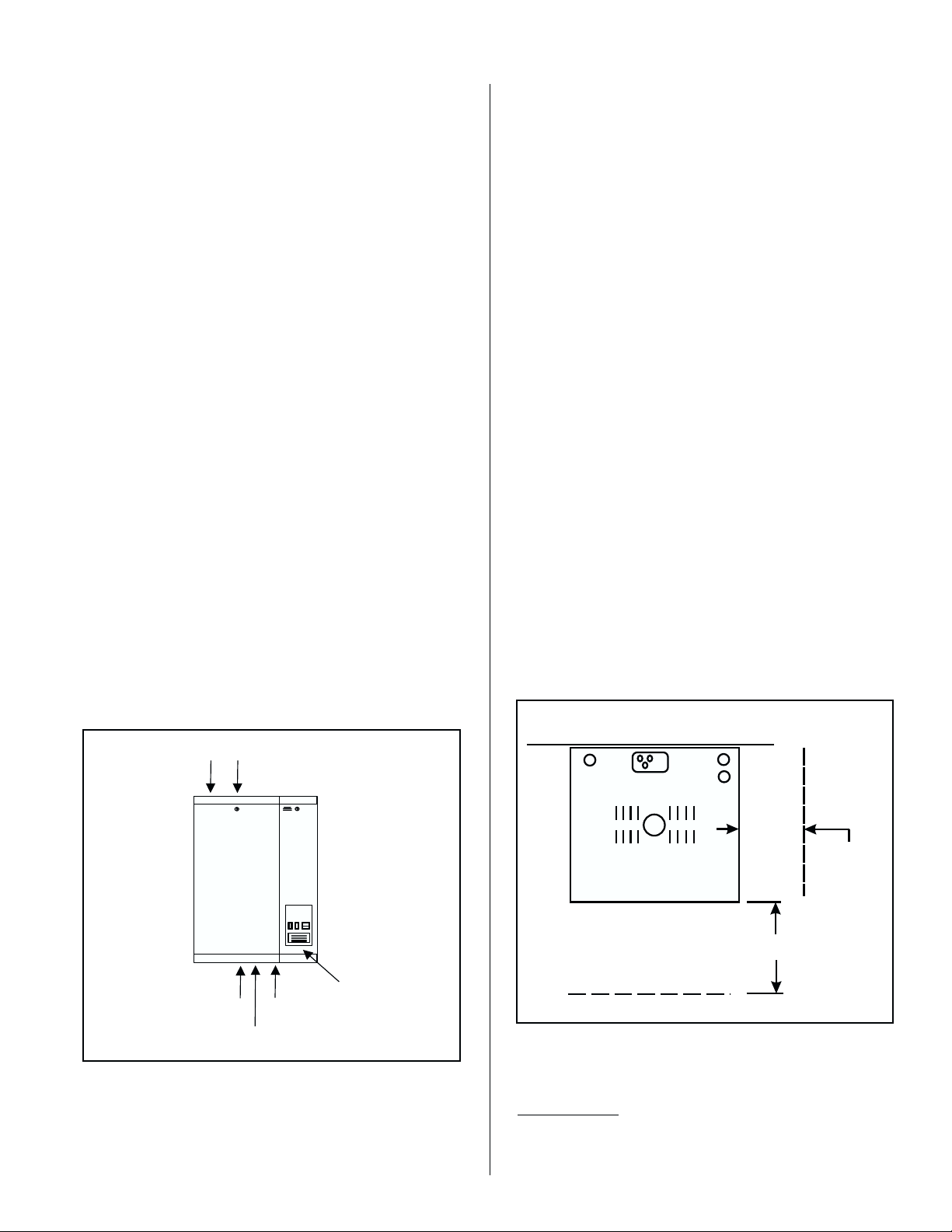
Figure #1
SGH Series Humidifier
Condensate
Return
Steam
Outlet
BASIC HUMIDIFIER CONFIGURATION
Liebert humidifier model SGH has a right side
electrical compartment. Each electrical compartment
has a hinge-down front door which is removable from
any partially or fully opened position. Each electrical
compartment has a screw-mounted right side cover
which can also be removed for ease of electrical
connection. For safety, the door when closed keeps
the side cover from being removed.
Single units have a plumbing compartment
attached to the left side of the electrical. Double units
have a second plumbing compartment. Each
plumbing compartment has a hinge-down front door
which is not intended to be removed. For safety, the
door must be closed in order to engage the lock. To
avoid any danger, never operate the humidifier with a
door off. For safety, each door when closed engages
its own safety interlock switch. All switches must be
engaged before the unit will operate.
To open the doors, unlock key, lift door up slightly
and pull top of door forward. Door will hinge 180
degrees and hang straight down. To remove door,
swing door parallel to floor. Then lift up slightly and
out. To reinstall door, hold parallel to floor and insert
hinge pins at bottom. The door can then be closed.
Figure #2
Clearance Requirements
WALL
WITHOUT BLOWER PACK
TOP VIEW
Power And
Control
Drain
Water
Su
Nameplate
Label
Wiring
2. Ensure that the dedicated external disconnect
is of sufficient size to handle the rated amps
as indicated on the nameplate label. Refer to
local codes.
NOTE: LOCAL AND NATIONAL
CODES MAY DEVIATE. PLEASE
CONSULT APPLICABLE CODES
FOR CLEARANCE REQUIREMENTS
IN ALL CASES.
MIN. 36"
FRONTAL
CLEARANCE.
LOCATION & MOUNTING
HUMIDIFIERS
SGH humidifiers are designed to mount on a
suitable wall or vertical surface. Do not sit on floor due
-1-
MIN. 36"SIDE
CLEARANCE
RECOMMENDED.
SEE NOTE.
Page 4
to clearances required for plumbing, electrical, and
control entrances. The clearance dimensions shown
in this manual are for reference only and are the
minimum required for maintenance of the humidifier.
Local and National Codes should be consulted prior to
final location and installation of the humidifier. Liebert
can not accept responsibility for installation code
violations.
In addition, install a minimum of 2 field
supplied fasteners in the holes provided in the
back of the unit to prevent the unit from being
bumped off the wall bracket.
6. Make sure humidifier is level.
7. DO NOT mount humidifier on hot surfaces.
1. Location of the humidifier should be below and
as close as possible to the steam distributor
location as possible.
2. For front and side clearance requirements (for
access during installation, maintenance and
troubleshooting), see Figure #2.
3. If possible, DO NOT locate humidifier any
further than absolutely necessary from steam
distributor location, as net output will be
reduced as a result of heat loss through steam
hose. Also, increased static pressure may
cause operational problems and necessitate
use of the fill cup extension kit and other
components.
4. Where possible, mount humidifier at a height
convenient for servicing.
5. Wall mounting bracket provided should be
securely attached horizontally and open edge
upwards, using field-supplied fasteners. Use
a minimum of 3 - #12 x 3" long wood screws,
or better, into a vertical structural surface. If
any spacer material is used between the
bracket and the structural material such as
drywall, increase fastener length accordingly.
8. If humidifiers are mounted on roof, a
thermostatically ventilated weatherproof
cabinet by others should be used. Consult
factory.
9. DO NOT mount humidifiers in an area where
freezing may occur.
10. DO NOT mount humidifiers on vibrating
surface.
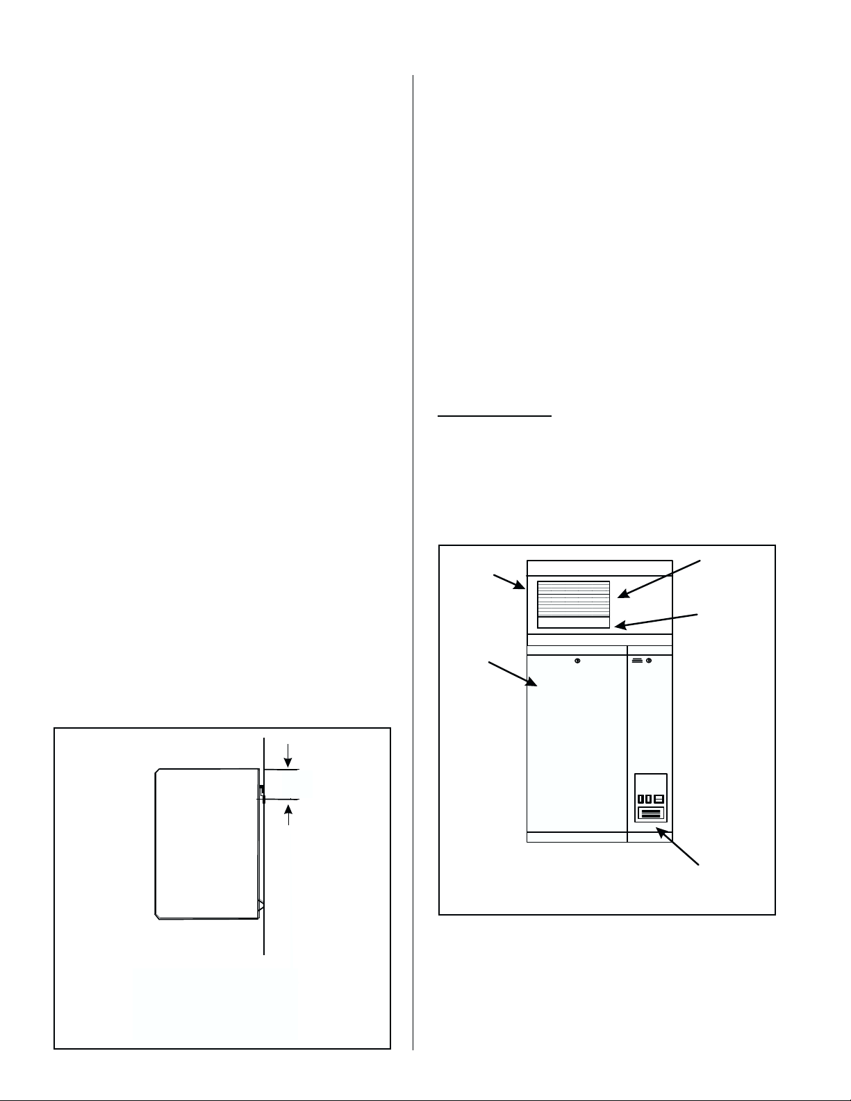
BLOWER PACKS
1. Blower packs are an optional accessory used
to directly distribute steam to localized areas
(such as computer rooms) or in structures that
do not have a built-in air distribution system.
Figure #4
Built On Blower Pack
Optional
Built-On
Blower Pack
Single
Circuit
Humidifier
Built-In
Supply Air
Grille
Built-In Steam
Distributor
Figure #3
Wall Bracket Mounting Detail
WALL
7.7”
FASTENWALL BRACKET
(FACTORYSUPPLIED)TO
WALLUSING ANCHOR BOLTS
(3) SUPPLIEDBY OTHERS
005-030
7.7"(19.6cm)
7.7"(19.6cm)A
050-200
A
(19.6 cm)
Power And
Control
Wiring
See Figure #6 for mounting clearances.
2. Blower packs are available integrally-mounted
on humidifier (built-on blower pack, BOBP,
see Figure #4) or detached and field-piped
and wired to humidifier (remote mounted
blower pack RMBP, see Figure #5).
-2-
Page 5
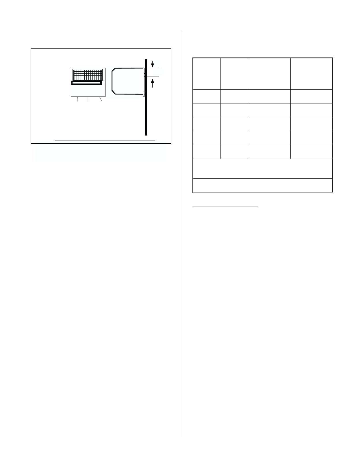
Figure #5
Remote Mounted Blower Packs (SGBP)
WALL
FRONT
CONDENSATE
See Figure #6 for mounting clearances.
STEAM
005-030
10-20
3.2" (8.0cm)
3. All SGH blower packs consist of a steel
cabinet containing: blower/motor powered by
voltage directly from the humidifier, fuse, relay,
speed select switch, stainless steel steam
distributor, supply air grille with adjustable
louvers, and built-in manual reset safety
thermostat to turn off the humidifier if the
blower pack gets overheated. Control
thermostat, mounted on the steam distributor,
starts the fan when steam is generated. When
supply voltage differs from voltage required to
run blower motor, blower pack will contain a
proper transformer. All blower packs provide
intake air filters.
4. Refer to Figure #6 for overhead and frontal
clearances required for blower packs.
Minimum clearance for the sides of the
Blower Pack unit is 12 inches. Dimensions
apply to both built-on and remote-mounted
versions of blower packs.
5. Mount remote blower pack(s) using factory
supplied wall mounting bracket, see Figure #5,
with clearance as recommended in Figure #6.
6. Steam distributor on the built-on and remote
blower packs have a hot surface that could
result in burns if touched. If space allows, we
recommend mounting at least 8 feet above the
floor.
7. Do not use blower packs as ducted blowers.
The air volume from a blower pack is not
sufficient to absorb the steam generated.
8.8. Pipe the steam line as stated in the STEAM
LINE section on page 6.
POWER AND
CONTROL
WIRING FROM
HUMIDIFIER
SIDE
050-100
050-100
3.2" (8.0cm)A
3.2”
(8 cm)
A
Figure #6
Overhead and Frontal Clearances for Blower
Packs
SGH
Model
Min.
Number
of Blower
Min. Overhead
Clearance
inches (cm)
Min. Front
Clearance
inches (cm)
Packs
010 1 18 (45) 30 (76)
020 1 18 (45) 36 (91)
050 1 36 (91) 84 (213)
100 1 48 (122) 156 (396)
200 2 42 (122) 156 (396)
*Remote mounted only. Four remote mounted blower
packs are recommended on the 200 model.
Nominal conditions 72ºF, 35% RH.
STEAM DISTRIBUTORS
1. Each cylinder requires its own steam line
and at least one distributor (do not join two
or more cylinders to one larger steam line).
Any cylinder’s steam line may be divided into
multiple branches to feed more than one
distributor. Steam supply line “tees” are
common copper fittings that are available for
this purpose.
2. Steam distributor locations are typically as
follows: supply air duct, return air duct, air
handling unit. Proper location should
consider: air temperature, relative humidity
before the distributor, air velocity, dimensions
of the location, amount of steam being
introduced into the duct, downstream
obstructions, and surfaces vulnerable to
wetting.
3. When steam distributors are located in a duct,
they should be in a straight section of duct at
least 6 feet (2 meters) from any elbow or
obstruction. If the duct or plenum conditions
result in poor absorption distance
characteristics, please consult your local
representative or the factory. See Figure #7.
4. Steam distributors should always span the
width of the air stream. Multiple steam
distributors, arranged in a bank, can
minimize absorption distance.
-3-
Page 6

d
6
Figure #7
Steam Distributor Location
'
Min.
6'
Mount Steam Distributor
At Least 6' (2 M) From Elbow
Multiple Steam Distributors
Can Reduce This Distance
Min.
5. Exercise extreme caution when installing in
fiber glass or internally lined ducts.
6. High positive or negative static pressure ducts
or plenums have special requirements. High
positive static pressure ducts may require the
unit to be fitted with a fill cup extension kit.
High negative static pressure ducts will likely
require the drain rate of the humidifier to be
increased to compensate for the reduced
drainage caused by the suction.
7. Vertical downflow ducts may induce an
artificial static pressure necessitating a fill cup
extension kit.
downward slope to the distributor will result in
poor condensate drainage and “spitting” of
condensate in duct. See Figure #9.
Figure #9
Leveling Distributor
Wrong
Support
(If Needed)
Correct
Always
Mount
Level
Wrong
Figure #10
Distributor Support
3/8" Threaded Rod
(Field Supplied)
8.
Low temperature ducts below 60 F (15 C),
shallow ducts, or branch ducts might require
the use of a field supplied condensate drain
pan below the steam distributor. See Figure
#8.
Figure #8
Condensate Drain Pan
SHALLOW DUCT
DRAIN PAN
T-BAR CEILING
TO DRAIN
BRANCH DUCT
DRAIN PAN
9. The steam distributor mounting plate is
perpendicular to the steam distributor. When
the mounting plate is attached to the side of
the duct, the distributor is level. An upward or
Duct
Steam Distributor
Figure #11
Cutting Duct for Mounting
1.
1. Steam Distributor Mounting Plate
2. Cut Hole In Duct For Insertion Using Template
3. Mount With Four Sheet Metal Screws
2. 3.
Hex Nut
Factory Attache
-4-
Page 7

10. Any distributor longer than 3 feet (1 meter)
should be supported at its end with a threaded
rod through top or bottom of duct. See Figure
#10.
below is proportioned accordingly. See Figure
#14. For short steam absorption systems see
Figure #13.
11. It is recommended that single distributors are
mounted near the bottom of the duct to ensure
the steam is dispersed into the majority of the
air flow. See Figure #12.
Figure #12
Single Steam Distributor Installation
Figure #14
Multiple Steam Distributors for Better Mixing
MIN. H = 16"
8"
4"
4"
2/5
H
2/5
1/5
1/3 1/31/3
H 20"
W 17"
4" 4"4"
Min. W = 12"
12. Using duct mounting template provided, cut a
hole in side of duct just large enough to admit
steam manifold and condensate drain pipe
assembly. Use four sheet metal screws to
attach mounting plate to side of duct. See
Figure #11 and #12.
13. With multiple steam distributors, the top steam
distributor should be at least 8" below top of
duct to avoid possible condensation on
surface of duct. The remainder of space
Figure #13
Multiple Steam Distributors
8"
Steam Header
PLUMBING
All water supply and drain line connections
should be installed in accordance with local
plumbing codes.
WATER SUPPLY LINE
1. Humidifier is intended to operate on potable
(cold) tap water.
2. If the raw water is very hard, Liebert can
provide longer cylinder life on softened water.
However, softened water is more conductive
and more corrosive. Some hardware and/or
software changes may be required, at time of
order or in the field. Consult local
representative.
3. DO NOT use a hot water supply to humidifier.
Minerals will adhere more easily to surfaces
and the fill valve’s small flow regulating orifice
could become plugged.
4. Standard fill valves are sized for water
pressure ranging from 30 to 150 psig. For
other pressures, consult local representative.
This pressure should be measured at the
humidifier if the water pressure is suspect.
-5-
Page 8

5. ALWAYS supply and install a shut off valve in
p
(55)
)
the water supply line dedicated to the
humidifier to facilitate servicing. Use ½"OD
copper to within 4 feet of the humidifier.
Reduce copper to 3/8" OD and connect to the
factory-supplied 3/8" olive compression fitting
under the humidifier.
DRAIN LINE
1. Humidifier is equipped with a 7/8" O.D.
unthreaded drain outlet on underside of drain
canal on bottom of the humidifier (see Figure
#15). A supplied reducer (see Figure #16)or
equivalent shall be installed on the drain line.
It will prevent backup in the drain pan and in
the cylinder due to partially blocked or badly
installed drain lines. This prevents rusting of
the drain pan and arcing due to
over-concentration. The drain canal has been
improved to prevent backup despite long or
gently sloped drain lines but it can not
compensate for flat or uphill runs.
Figure #15
Drain Line Connection
B
Bottom View
codes prohibit it. Route to a floor drain or
equivalent for safety reasons, since drain
water from humidifier can be very hot.
3. Keep drain lines as short as possible. Keep
drain lines sloped down, not level and not
up since low spots in drain lines will
accumulate sediment and cause backup.
The drain line should be 1" O.D. copper pipe
or larger. Do not use plastic pipe for drain
lines.
STEAM LINE
1.1. Steam lines for SGH models 010 through 020
require a minimum 7/8" O.D. (nominal 3/4")
copper pipe. For steam runs longer than 20 ft
use insulated nominal 1" copper to ensure the
draining of condensate.
2. Field-supplied hard copper with ½" thick
snap-on insulation is recommended for
steam supply, with Liebert supplied steam
hose coupling used to make connection to
cylinder. See Figure #17.
Figure #17
Steam Line Connection
Clamp To Steam Distributor
Or Remote Blower Pack
A
MODEL A in. (mm) B in. (Mm)
010-020 1.0 (25) 5.0 (127)
050-100 2.2 (55) 6.2 (158)
200 LEFT 2.2 (55) 6.2 (158)
200 RIGHT 2.2
Figure #16
FactorySupplied
Taperedcut is
recommended
Air Gap
NOTE: Steam hose should not reach bottom of the funnel.
In the event the building drain is plugged this becomes an
oint.
overflow
Wall
19.6(498
ClampAnd
7/8"I.D. Hose
Copper Reducer
(11/4” -3/4”) To
Serve As Funnel
Drain.Factory
supplied.
3/4”Copper Pipe
(NotSupplied)
See Section On
Condensate
Return Line
Trap
Figure #18
Sloping the Steam Line
Trap
* See Section On
Condensate
Return Line
Field Supplied
Insulated Hard
Copper Pipe
Or Flexible
Steam Hose
Available
From Factory
Min. 10 Degree Slope
Min. 12"
2.
The drain line should not end in a sink used
frequently by personnel, or where plumbing
NOTE: Trap must be 3' minimum down from steam distributor.
If not, condensate must be routed to drain.
-6-
Page 9

3. Liebert steam supply hose or field-supplied
piping should be sloped downwards from the
steam distributors to the humidifier. Slope
should be at least 2" in 12" to promote
condensate runback. See Figure #18. If this
slope is not possible, condensate must be
removed before the distributor. See Figure
#19.
Figure #19
Long Steam Lines
6. To ensure odor-free steam, always use Liebert
steam hose. Check steam hose and hose
couplings periodically for cracks, breaks,
kinks. Replace as required. DO NOT
substitute hose. Liebert is not responsible for
health effects or damage from substitute hose.
7. Steam lines for SGH 050 through 200 require
1-5/8" O.D. (nominal 1-1/2") copper pipe. For
steam runs longer than 40 ft use insulated
nominal 2" copper to ensure the draining of
condensate.
8. Do not use steel or plastic pipe for steam
distribution, or hose other than Liebert
supplied. Substitution will void warranty.
Condensate To Drain
4. Minimize the length of steam line and keep it
as straight as possible, minimizing bends.
Also, avoid using 90 elbows. Wherever
possible, use long radius turns (using tube
bender on oversized copper or pairs of 45
elbows). This will reduce the condensate
generated by heat loss. This will also reduce
the back pressure and avoid the need to
buy/install an accessory Fill Cup Extension Kit.
See Figure #22.
5. Ensure that the steam hose does not kink or
sag. The steam hose becomes more flexible
when hot. The hose should be supported to
prevent water traps. Only use steam hose for
connections or steam lined runs of 5 feet or
less. See Figure #20.
Figure #20
Steam Hose Routing
AVOID KINKS
AVOID WATER TRAPS
9. If steam line is routed below steam distributor
or if the steam distributor is lower than the
humidifier, a condensate trap ‘tee’ will be
required to remove water at this low point.
Run condensate from trap to nearest drain
lower than the distributor. See Figure #21.
Figure #21
Condensate Tee at any Low Point in Steam Line
NOT ACCEPTABLE
WITHOUT TRAP "TEE"
OBSTRUCTION
HUMIDIFIER
CONDENSATE "TEE"
AT LOW POINT IN
STEAM HOSE
CONSULT FACTORY
CREATE A FALSE LOW POINT TO REMOVE
CONDENSATE WHENEVER THE
STEAM LINE MUST APPROACH THE
DISTRIBUTOR FROM ABOVE.
DUCT
TO FLOOR
DRAIN
10. All built-on blower packs are factory-fitted with
all steam hose connections. No further work
is required.
GENTLE
SWEEPING
TURNS
PROPER
SLOPE
11. Do not run steam line more than 1 foot per
lb/hr output. Example, 10 lbs/hr should not
have a steam run longer than 10 feet. If long
runs are unavoidable, the humidifier should be
sized larger to compensate for condensate
losses and insulated copper should definitely
be used.
-7-
Page 10

ACCESSORIES - FILL CUP EXTENSION KIT(S)
1. The SGH humidifier is an electrode humidifier.
It produces steam at atmospheric pressure.
Pressure head must develop to push steam
through supply line and into air duct.
2. Combined resistance of duct positive static
pressure and steam line resistance creates a
small pressure head in steam cylinder. Total
amount of positive static pressure head is
reflected directly by water column differential
that develops between water in the fill cup
hose feeding cylinder and water level in
cylinder.
3. Standard dimensions of humidifier limit static
that can be tolerated before water will be
pushed high enough to spill over into overflow
tube in fill cup assembly.
condensate hose with clamps is supplied with
Liebert’s steam distributors to serve as a
flexible coupling. DO NOT direct solder field
copper condensate line to steam distributors.
2. Always incorporate a trap in routing of
condensate return line. Condensate that
accumulates in trap will prevent possibility of
steam escaping. Depth of trap must exceed
duct static pressure by 2 inches of water
column. See Figure #23.
Figure #23
Trap to Prevent Steam in Condensate Line
4. To increase allowable water column (allowable
positive static pressure) an accessory Fill Cup
Extension Kit is available from Liebert. See
Figure #22.
Figure #22
Fill Cup Extension Kit to Overcome Static Pressure
FILLCUP BRACKET
FILLCUP
OVERFLOWHOSE
FILLHOSE TO
CYLINDER
HOSEFROMFILLVALVE
3 FEET MINIMUM
TRAP
CONDENSATE TRAP
DEPTH OF TRAP
MUST BE 2" MORE THAN
DUCT STATIC PRESSURE
OF WATER COLUMN
3. Condensate return line can not be run back to
fill cup if humidifier is within 36" of being level
with steam distributor. See Figure #18.
4. If steam distributor is mounted level with or
below humidifier, condensate line must be
routed to nearest floor drain or to a
condensate pump (available from Liebert).
See Figure #24.
Figure #24
Drain Pump (if necessary)
CONDENSATE RETURN LINE
1. Each steam distributor has a built-in
condensate return (3/8" O.D. copper tubing).
Flexible condensate return hose (3/8" I.D.)
available from Liebert, is recommended for
routing condensate back into humidifier’s fill
cup. Note: A short length of 3/8" O.D. copper
tubing is supplied by Liebert for use when
routing condensate hose back to humidifier’s
fill cup. Similarly, a short length of 3/8" I.D.
-8-
Humidifier
Drain Line
Line
Floor
Surface
Drain
Pump
5. Provide a “U” trap in condensate line even
when distributor is located in return air
plenum. It stops a suction action from
Page 11

impeding condensate flow when duct
pressures are below atmosphere.
on the steam distributor, starts the fan when
steam is generated.
6. The condensate line can go to either of two
large holes in the fill cup cover on top of
humidifier.
7. It is not necessary to return the condensate to
the humidifier.
8. Long condensate runs (more than twenty feet)
should be sloped well and be constructed out
of ½" nominal copper pipe to ensure flow.
ELECTRICAL
PRIMARY VOLTAGE SUPPLY WIRING TO
HUMIDIFIER
1. Check and ensure that available voltage and
phase corresponds with operating voltage and
phase of humidifier as indicated on the
humidifier nameplate label (see Figure #1).
2. Ensure that an adequate power supply is
available to carry full humidifier amperage
drawn as specified by rated amps on the
humidifier nameplate label refer to local codes.
3. A dedicated external disconnect must be
installed. Do not exceed the maximum circuit
protection amps as indicated on the
nameplate label.
4. Connect ground wire to cabinet ground clamp.
Do not use neutral wire of four wire supply as
ground.
5. Single phase humidifiers may be run on three
phase power, but load may unbalance power
grid.
6. External wiring sizes must be in accordance
with NEC and/or CEC and existing local
electrical codes and by-laws.
PRIMARY VOLTAGE SUPPLY WIRING FROM
HUMIDIFIER(S) TO BLOWER PACKS
1. All blower packs are wired (by factory if
built-on, by others if remote mounted) to be
powered from the humidifier.
2. As a safety feature, blower packs come
equipped with a manual reset safety
thermostat and relay built into the blower pack
cabinet. The manual reset thermostat turns
off the humidifier if the blower pack gets
overheated. The control thermostat, mounted
3. All blower packs have high efficiency blowers
to minimize the frontal and overhead
clearance required to absorb the steam.
4. All built-on blower packs are factory wired to
humidifier. Primary voltage wiring to
humidifier, as described in electrical primary
voltage supply wiring, is all that is required to
power humidifier and blower packs.
5. Remote mounted blower packs require field
wiring between two primary voltage terminal
blocks and two low voltage control (class 1
circuit wiring required) terminal strips; one of
each located in humidifier and remote blower
pack cabinet. To properly access the primary
block on the humidifier, it may be necessary to
remove the side. To connect the primary and
control (class 1 circuit wiring required) wiring,
the wiring is fed through the knockouts
provided in the bottom of the blower pack.
The terminal block and strip are accessed by
removing the blower pack cover.
6. Field wiring of remote blower packs must
conform to national and local electrical codes.
Refer to wiring diagram supplied inside the
humidifier.
7. Use approved wire for power connection from
two pole terminal block of remote blower pack
to additional two pole terminal block inside
electrical section of humidifier.
8. Use approved wire to connect from ground
clamp of remote mounted blower pack to
ground clamp provided in the electrical section
of humidifier.
LOW VOLTAGE CONTROL WIRING
On-Off Controls
Figure #25
External Wiring of On/Off Controls
A
B
C
EXTERNAL
INTERNAL
810
Controls are available from Liebert as accessories.
If controls were not ordered with humidifier, they must
be purchased supplied by others. The following
-9-
Page 12

information is relevant to all controls, factory supplied
VariesWithEach
or otherwise.
A, B and C (described below) are to be wired in
series (only one path for current) across terminals 8
and 10 on the low voltage control terminal strip, or
replaced with a jumper wire for constant operation
(see Figure #27). Caution: If any control field wiring
touches ground metal unit, safeties will be bypassed.
A - Wall or Duct Mounted Control On/Off
Humidistat: Wired to make on drop in humidity, break
on rise to setpoint. Set to desired % RH. Can be a
make/break set of contacts from a Building Automation
System.
B - Duct Mounted Safety High Limit On/Off
Humidistat (if used): Wired to make on drop in
humidity, break on rise to safety setpoint. Set to
approximately 85% RH as a safety to help prevent
saturation and wetting in the duct.
or down stream from distributor. Mount it
where air’s humidity and temperature are
uniform and representative of spaces being
humidified.
3. Mount duct high limit humidistat
downstream of steam distributors far enough
that, under normal humidity and air flow
conditions, steam will have been fully
absorbed (typically at least 10 feet). It must
be located to sense high humidity only when
uniform and representative air is
over-humidified or approaching saturation.
4. Mount duct air-proving switch so that it is
able to sense air flow or lack of it. Wire it to
make when air flow is sensed and break when
air flow fails. Mount prior to distributor.
5. Check operation of all on/off controls before
starting humidifier.
C - Duct Mounted Safety Air-Proving On/Off
Switch (if used): Wired to make when sensing air
flow, break when no air flow. Used as a safety to
prevent saturation when no air flow.
1. Liebert offers various versions of A, B and C to
suit each application. In general, A is
essential, whereas B and C are highly
recommended in ducted applications.
2. Field wiring from humidistat to humidifier and
between devices should be 18 AWG or
heavier and kept as short as possible.
3. Low voltage control terminal strips are
provided in the electrical compartment.
Internal sides are factory wired. External
sides are to be field wired.
4. Each humidifier is supplied with a wiring
diagram inside.
CONTROL INSTALLATION
1. Mount any wall humidistat (control or high
limit) over standard electrical box at height
similar to typical thermostat. Any wall
humidistat should be in location
representative of overall space being
humidified and not in path of blower pack or
air supply grille. Do not mount on a outside
wall where temperature fluctuation can affect
control response.
2. Mount duct humidistat in location
representative of overall air humidity, usually
return duct. Do not mount it directly in front of
steam distributor or in turbulent or mixing zone
6. Calibration of controls (on/off or modulation) in
the field may be necessary due to shipping
and handling. Verify humidistat accuracy
before commissioning system.
OPTIONAL MODULATION (CONTINUOUS
CONTROLS) (see Figure #28)
1. Read on/off controls section first since it is
necessary to all control systems.
2. Virtually any modulation (continuous control)
external hardware by others (as long as it has
%RH setpoint circuitry) may be interfaced with
pre-specified factory-configured SGH pc
board via the control terminal strip.
3. Modulation (continuous control) by others for
use with SGH humidifiers involves one of
several control wiring diagrams. In all cases,
modulating signal interfaces through control
terminal strip to main pc board inside
humidifier.
Figure #26
Typical Modulation Wiring
Modulation Option
See Liebert Supplied
External Wiring Diagram
A
B
C
External
Internal
810 32 30
_
y
-10-
Page 13

4. The modulation signal must increase from
minimum toward maximum as sensed RH
(actual RH) drops below desired RH (%RH
setpoint). In response, humidifier’s steam
output will increase from minimum toward
maximum. When humidifier’s steam output
(lbs/hr) matches humidification load (lbs/hr),
modulation signal will stabilize.
and the humidifier starts its operation. The controller
waits 10 seconds before energizing the on-board
relays. When the relays energize, heating voltage is
delivered to the cylinder. After a 30 second delay, the
fill valve is activated (if the output from the cylinder is
below 100 %). If controller detects increase of
amperage above allowed range, the unit will activate
drain valve for 2 seconds.
5. Field-wiring connections for modulation control
are to be made to external side of terminals 30
and 32 on humidifier’s control terminal strip.
Always refer to the external control’s wiring
diagram factory supplied with each Liebert
modulation control option.
6. Varying dc Voltage Modulation Signal
Powered by Others: SGH humidifier can be
factory configured to accept the following vdc
signals: 0-10 vdc, or 2-10 vdc. Wire
according to Liebert supplied external wiring
diagram that comes with each modulation
option. To share the signal with more than
one humidifier, wire in parallel to each
humidifier. If a different signal is desired
consult factory.
7. Varying dc milliAmp (mA) Modulation
Signal Powered by Others: SGH humidifier
can be factory-configured to accept a standard
dc mA signal, if pre-specified. Wire according
to Liebert supplied external wiring diagram
that comes with each modulation option.
Choose from 0-20 dc mA or 4-20 dc mA. To
share the signal with more than one humidifier
consult factory.
OPTIONAL MODULATION (CONTINUOUS
CONTROL) PACKAGES BY LIEBERT
Modulation (continuous control) “packages” are
offered as accessories by Liebert.
OPERATION
During operation, the controller measures the rate
at which water is converted to steam and thus the
mineral content of water inside the cylinder. When this
rate exceeds the design optimum, a drain of the
cylinder takes place. The amount of water drained is
just enough to keep the contained water at design
levels.
During start up, when mineral content in the water
is low, water will reach the top of the cylinder at which
point the yellow indicator light will come on. This is
normal operation with a fresh cylinder. After a period of
time the water level will drop and the yellow light will
turn off.
High water level in the cylinder also indicates that
the cylinder is near the end of its service life as
electrodes become coated with minerals. The yellow
light coming on more often would be the first indication
of approaching the end of the cylinder life.
SGH OPERATION
END OF CYLINDER LIFE
When the cylinder is used up and water level can
no longer stabilize below full cylinder (due to fully
coated electrodes), the yellow light will flash in 4 pulse
cycles. At this time the control board interrupts steam
production and switches the green indicator lamp off.
The disposable cylinder must be replaced.
It is wise to keep a new replacement cylinder on
hand to avoid downtime when it becomes time to
change the disposable cylinder.
INTRODUCTION
When the humidifier is first turned on, the
controller starts with a self test procedure, which takes
about 10 seconds. The test consists of activating for a
short time the drain valve, fill valve, and power relays.
The sound of the working solenoids is an indication of
valves operation. Green and yellow lights flash during
this time.
If there is no call for humidity, the humidifier is
standing by and green light flashes. When control loop
is closed ( Figure #13), the green light is steady on
MANUAL CAPACITY ADJUSTMENT
On/Off Controls
The SGH humidifier is rated in lbs/hr of steam
output capacity. Set to 100%, it will operate at full
output until the humidistat has sensed that the
humidity has reached setpoint. Then it will stop the
humidifier by breaking control circuit 8-10.
If the humidifier is oversized, the humidistat will be
quickly satisfied and stop the humidifier. As humidity
level drops the humidistat calls again. It is quickly
-11-
Page 14

satisfied and stops again. The resultant short-cycling
is easily overcome.
using a screwdriver, press the reset button (marked
with a red dot) inside the blower packs.
A manual capacity adjustment potentiometer
(“pot”) is provided on the SGH main pc board for that
purpose. It is marked “CAPACITY ADJUST” and is
adjustable from 25 to 100% of rating.
Modulation Control
The SGH humidifier, utilizing modulation control,
does not have the same problems of over sizing. It
reacts to the modulation signal and varies its capacity
automatically. However, if you wish to turn down the
capacity, use the manual capacity adjustment
potentiometer (“pot”).
OTHER POTENTIOMETERS
Do not adjust any other potentiometers (“pots”)on
the pc board(s). They are factory-set and not meant to
be user-set.
DETECTING WATER SUPPLY DEFICIENCY
Knowing how long it normally takes to fill each size
steam cylinder, each humidifier’s pc board is factory
configured to an acceptable maximum filling time. If it
is filling too slowly, when the time expires the
electronics stops the humidifier. To indicate this, the
green light goes out and the yellow light goes on.
Units are also equipped with speed select switch.
The switch is located on the right-hand side of the
blower, inside the blower pack. To access the switch,
remove right-hand side intake air filter.
To avoid condensation on the cabinet parts, run
blower pack on high speed when humidifier delivers
more than 50 lbs/hr of steam.
REMOTE INDICATION
Every SGH comes factory wired as a set of dry
contacts at 61-20 on the control terminal strip. The
user can connect an indicator externally to 61-20. It
will automatically be activated any time a fault is
detected.
DOUBLE UNIT OPERATION
Turn both switches on. If there is a demand for
humidity, the green status lamp will indicate that the
circuit is operating.
BLOWER PACK OPERATION
Blower packs are equipped with a control
thermostat mounted on the steam distributor. As soon
as humidifier generates steam, the contact is closed
and the fan is started. When steam is no longer being
generated, the fan cuts out with a delay.
If blower packs get overheated (malfunction of the
air circulation), the manual reset safety thermostat
interrupts the steam generation. To reset, switch off
the humidifier and wait until the steam distributor cools
down. Then remove left-hand side intake air filter and,
-12-
Page 15

LIMITED WARRANTY
Liebert Corporation (hereinafter collectively referred to as THE COMPANY),
warrant for a period of two years from date of shipment, that THE COMPANY’s
manufactured and assembled products, not otherwise expressly warranted (with the
exception of the cylinder) are free from defects in material and workmanship. No
warranty is made against corrosion, deterioration, or suitability of substituted materials
used as a result of compliance with government regulations.
THE COMPANY’s obligations and liabilities under this warranty are limited to
furnishing replacement parts to the customer, F.O.B. THE COMPANY’s factory,
providing the defective part(s) is returned freight prepaid by the customer. Parts used
for repairs are warranted for the balance of the term of the warranty on the original
humidifier or 90 days, whichever is longer.
The warranties set forth herein are in lieu of all other warranties expressed or
implied by law. No liability whatsoever shall be attached to THE COMPANY until said
products have been paid for in full and then said liability shall be limited to the original
purchase price for the product. Any further warranty must be in writing, signed by an
officer of THE COMPANY.
THE COMPANY’s limited warranty on accessories, not of Liebert’s manufacture,
such as controls, humidistats, pumps, etc. is limited to the warranty of the original
equipment manufacturer from date of original shipment of humidifier.
THE COMPANY makes no warranty and assumes no liability unless the
equipment is installed in strict accordance with a copy of the catalog and installation
manual in effect at the date of purchase and by a contractor approved by THE
COMPANY to install such equipment.
THE COMPANY makes no warranty and assumes no liability whatsoever for
consequential damage or damage resulting directly from misapplication, incorrect sizing
or lack of proper maintenance of the equipment.
THE COMPANY retains the right to change the design, specification and
performance criteria of its products without notice or obligation.
Page 16

Model # :_________________________
Serial # :__________________________
Cylinder # :_________________________
Cylinder Last Replaced:
_________________________
MTH/DAY/YR
_________________________
MTH/DAY/YR
_________________________
MTH/DAY/YR
Listed
Humidifier
E65185
LIEBERT CORPORATION
1050 Dearborn Drive, P.O. Box 29186
Columbus, Ohio 43229
Tel: (614) 888-0246 • Fax: (614) 841-6882
LR-35859
PRINTED IN CANADA
 Loading...