

Liebert Series 610 User Manual

POWER AVAILABILITY
CONTINUOUS POWER-TIE CONFIGURATION
USER MANUAL
Series 610
Multi-Module UPS


i
TABLE OF CONTENTS
1.0 SYSTEM DESCRIPTION . . . . . . . . . . . . . . . . . . . . . . . . . . . . . . . . . . . . . . . . . . . . . . . . . . . . 1
1.1 Function . . . . . . . . . . . . . . . . . . . . . . . . . . . . . . . . . . . . . . . . . . . . . . . . . . . . . . . . . . . . . . . . . . . 1
1.2 System Flexibility. . . . . . . . . . . . . . . . . . . . . . . . . . . . . . . . . . . . . . . . . . . . . . . . . . . . . . . . . . . . 1
1.3 Inter-System Isolation and Reliability . . . . . . . . . . . . . . . . . . . . . . . . . . . . . . . . . . . . . . . . . . . 1
1.4 Control System Features . . . . . . . . . . . . . . . . . . . . . . . . . . . . . . . . . . . . . . . . . . . . . . . . . . . . . . 5
1.5 Operational Description. . . . . . . . . . . . . . . . . . . . . . . . . . . . . . . . . . . . . . . . . . . . . . . . . . . . . . . 5
1.5.1 Operational Choices . . . . . . . . . . . . . . . . . . . . . . . . . . . . . . . . . . . . . . . . . . . . . . . . . . . . . . . . . . . 5
1.5.2 Momentary Tie Operation . . . . . . . . . . . . . . . . . . . . . . . . . . . . . . . . . . . . . . . . . . . . . . . . . . . . . . 6
1.5.3 Continuous Tie . . . . . . . . . . . . . . . . . . . . . . . . . . . . . . . . . . . . . . . . . . . . . . . . . . . . . . . . . . . . . . . 7
1.5.4 Tie System Components . . . . . . . . . . . . . . . . . . . . . . . . . . . . . . . . . . . . . . . . . . . . . . . . . . . . . . . . 8
1.5.5 Modes of Operation. . . . . . . . . . . . . . . . . . . . . . . . . . . . . . . . . . . . . . . . . . . . . . . . . . . . . . . . . . . . 9
2.0 OPERATION DESCRIPTION. . . . . . . . . . . . . . . . . . . . . . . . . . . . . . . . . . . . . . . . . . . . . . . . . 11
2.1 Continuous Power-Tie . . . . . . . . . . . . . . . . . . . . . . . . . . . . . . . . . . . . . . . . . . . . . . . . . . . . . . . 11
2.2 Separating Tied Systems . . . . . . . . . . . . . . . . . . . . . . . . . . . . . . . . . . . . . . . . . . . . . . . . . . . . . 13
2.3 Load Transfers Between UPS Systems. . . . . . . . . . . . . . . . . . . . . . . . . . . . . . . . . . . . . . . . . . 13
2.4 Combined Loads on One System from Continuous Tie Operation . . . . . . . . . . . . . . . . . . . . 14
2.5 Combined Loads on One System to Continuous Tie Operation. . . . . . . . . . . . . . . . . . . . . . . 14
2.6 Design Criteria . . . . . . . . . . . . . . . . . . . . . . . . . . . . . . . . . . . . . . . . . . . . . . . . . . . . . . . . . . . . . 14
2.7 Improper User Operation. . . . . . . . . . . . . . . . . . . . . . . . . . . . . . . . . . . . . . . . . . . . . . . . . . . . . 18
2.8 Tie Circuit Breaker or Logic Faults . . . . . . . . . . . . . . . . . . . . . . . . . . . . . . . . . . . . . . . . . . . . 19
2.8.1 What Happens If a Failure Occurs During a Power Transfer . . . . . . . . . . . . . . . . . . . . . . . . . 19
2.8.2 What Happens If a Logic Failure Occurs During Power Transfer . . . . . . . . . . . . . . . . . . . . . 19
2.8.3 Hardware Failures . . . . . . . . . . . . . . . . . . . . . . . . . . . . . . . . . . . . . . . . . . . . . . . . . . . . . . . . . . . 19
2.9 Recommendations - Tie Circuit Breaker Selection. . . . . . . . . . . . . . . . . . . . . . . . . . . . . . . . . 19
3.0 CONTROL PANEL DESCRIPTION . . . . . . . . . . . . . . . . . . . . . . . . . . . . . . . . . . . . . . . . . . . .20
3.1 Mimic Panel . . . . . . . . . . . . . . . . . . . . . . . . . . . . . . . . . . . . . . . . . . . . . . . . . . . . . . . . . . . . . . . 20
3.2 Load Transfer Controls . . . . . . . . . . . . . . . . . . . . . . . . . . . . . . . . . . . . . . . . . . . . . . . . . . . . . . 21
3.3 Continuous Tie Control . . . . . . . . . . . . . . . . . . . . . . . . . . . . . . . . . . . . . . . . . . . . . . . . . . . . . . 23
3.4 Control Inhibits . . . . . . . . . . . . . . . . . . . . . . . . . . . . . . . . . . . . . . . . . . . . . . . . . . . . . . . . . . . . 23
3.5 Manual Controls. . . . . . . . . . . . . . . . . . . . . . . . . . . . . . . . . . . . . . . . . . . . . . . . . . . . . . . . . . . . 24

ii
4.0 OPERATING INSTRUCTIONS . . . . . . . . . . . . . . . . . . . . . . . . . . . . . . . . . . . . . . . . . . . . . . . .25
4.1 Initial System Start-Up . . . . . . . . . . . . . . . . . . . . . . . . . . . . . . . . . . . . . . . . . . . . . . . . . . . . . . 25
4.2 Basic Operation . . . . . . . . . . . . . . . . . . . . . . . . . . . . . . . . . . . . . . . . . . . . . . . . . . . . . . . . . . . . 25
4.2.1 Momentary Tie - Load Transfers . . . . . . . . . . . . . . . . . . . . . . . . . . . . . . . . . . . . . . . . . . . . . . . . 25
4.2.2 Normal Transfer Operation Configurations . . . . . . . . . . . . . . . . . . . . . . . . . . . . . . . . . . . . . . . 25
4.2.3 Maintenance Procedures - Isolating Each UPS System. . . . . . . . . . . . . . . . . . . . . . . . . . . . . . 25
4.2.4 Isolating a UPS System for Maintenance - Combined Loads Operation. . . . . . . . . . . . . . . . . 26
4.2.5 Transfer of Load Between Two Systems . . . . . . . . . . . . . . . . . . . . . . . . . . . . . . . . . . . . . . . . . . 26
4.2.6 Returning an Isolated System to Normal Operation - End Combined Loads Operation. . . . 27
4.2.7 Maintenance Procedures - Maintaining Power-Tie Components . . . . . . . . . . . . . . . . . . . . . . 27
4.2.8 Maintenance Procedures - Tie Control Logic Components . . . . . . . . . . . . . . . . . . . . . . . . . . . 27
4.2.9 Abnormal Operations . . . . . . . . . . . . . . . . . . . . . . . . . . . . . . . . . . . . . . . . . . . . . . . . . . . . . . . . . 28
4.2.10 Trouble Recovery . . . . . . . . . . . . . . . . . . . . . . . . . . . . . . . . . . . . . . . . . . . . . . . . . . . . . . . . . . . . 28
4.2.11 Continuous Tie-Systems. . . . . . . . . . . . . . . . . . . . . . . . . . . . . . . . . . . . . . . . . . . . . . . . . . . . . . . 29
4.2.12 Isolation for Maintenance . . . . . . . . . . . . . . . . . . . . . . . . . . . . . . . . . . . . . . . . . . . . . . . . . . . . . 31
4.2.13 Operation Scenarios/Transfer Procedures . . . . . . . . . . . . . . . . . . . . . . . . . . . . . . . . . . . . . . . . 33
FIGURES
Figure 1 Basic Dual-Bus Power-Tie one-line diagram. . . . . . . . . . . . . . . . . . . . . . . . . . . . . . . . . . . . . . . . . . . 2
Figure 2 Power-Tie systems - fault isolation issues . . . . . . . . . . . . . . . . . . . . . . . . . . . . . . . . . . . . . . . . . . . . . 3
Figure 3 Power-Tie systems - control interface diagram . . . . . . . . . . . . . . . . . . . . . . . . . . . . . . . . . . . . . . . . . 4
Figure 4 Power-Tie system one-line diagram . . . . . . . . . . . . . . . . . . . . . . . . . . . . . . . . . . . . . . . . . . . . . . . . . 10
Figure 5 Control panel layout . . . . . . . . . . . . . . . . . . . . . . . . . . . . . . . . . . . . . . . . . . . . . . . . . . . . . . . . . . . . 12
Figure 6 Power-Tie system - fault isolation issues. . . . . . . . . . . . . . . . . . . . . . . . . . . . . . . . . . . . . . . . . . . . . 16
Figure 7 Power-Tie systems - fault tolerance . . . . . . . . . . . . . . . . . . . . . . . . . . . . . . . . . . . . . . . . . . . . . . . . . 17
Figure 8 Power-Tie system one-line diagram . . . . . . . . . . . . . . . . . . . . . . . . . . . . . . . . . . . . . . . . . . . . . . . . 32
Figure 9 From start-up to normal operation, loads to be split between two distribution feeders . . . . . . . 33
Figure 10 From combined loads operation to loads split between two feeders . . . . . . . . . . . . . . . . . . . . . . . 33
Figure 11 From continuous tied systems to loads split between two systems . . . . . . . . . . . . . . . . . . . . . . . 33
Figure 12 Transfer both load feeders to one UPS . . . . . . . . . . . . . . . . . . . . . . . . . . . . . . . . . . . . . . . . . . . . . . 34
Figure 13 Both feeders on one system to normal operation . . . . . . . . . . . . . . . . . . . . . . . . . . . . . . . . . . . . . . 34
Figure 14 Transfer 100% load on one system to 100% load on a second system (a two-step operation) . . . 34
Figure 15 Normal split load operations to Continuous Tie . . . . . . . . . . . . . . . . . . . . . . . . . . . . . . . . . . . . . . 35
Figure 16 Continuous Tie to normal split load operation . . . . . . . . . . . . . . . . . . . . . . . . . . . . . . . . . . . . . . . . 35
Figure 17 Continuous Tie to load on one system . . . . . . . . . . . . . . . . . . . . . . . . . . . . . . . . . . . . . . . . . . . . . . 35
Figure 18 Load on one system to Continuous Tie . . . . . . . . . . . . . . . . . . . . . . . . . . . . . . . . . . . . . . . . . . . . . . 36
Figure 19 One system in bypass to both feeders combined on remaining operational system . . . . . . . . . . 36
Figure 20 One system in bypass to Continuous Tie operation (Option 1) . . . . . . . . . . . . . . . . . . . . . . . . . . . 37
Figure 21 One system in bypass to Continuous Tie operation (Option 2) . . . . . . . . . . . . . . . . . . . . . . . . . . . 37

System Description
1
1.0 SYSTEM DESCRIPTION
1.1 Function
The Liebert Continuous Power-Tie™ system provides the capability to momentarily or continuously
parallel the output buses of two otherwise independent UPS Systems (See Figure 1). It also provides
manually initiated, uninterrupted transfers of a critical load bus between the two UPS Systems.
This topology permits one UPS and its associated distribution system to be shut down for maintenance while the load continues to be supplied by another UPS, without the necessity of transferring
the load to bypass during shutdown or restart of the UPS being maintained.
1.2 System Flexibility
In the unlikely event that one or both UPS systems have only partial available capacity (e.g., loss of
one or more modules in an otherwise functional system), this partial capacity system can be continuously tied to a second full (or partial) capacity system, powering simultaneously the now-tied two critical buses.
This results in a single, fully redundant UPS system powering two different distribution strings
through a single UPS critical bus.
When the off-line (whether for maintenance or repair) modules are brought on-line again, the two
UPS critical buses are again separated without the need to transfer to the bypass source. For continuous-tied systems, module kVA and kW ratings must be identical.
1.3 Inter-System Isolation and Reliability
For multiple UPS installations at a single site, best total system reliability is achieved when systemto-system independence is maximized. However, to transfer loads or parallel critical buses between
multiple UPS systems, a certain amount of cross-connected system-to-system power and signal conductors are required. See Figure 2.
Proper implementation of power conductor runs and circuit breaker placement will minimize the risk
that a catastrophic critical bus fault (e.g., a dropped wrench) on one system will cause a failure in a
second system.
Liebert has minimized the risk of system-to-system electrical noise susceptibility and faults in system-to-system copper wire control circuitry through the use of fiber-optic technology as well as transformer and impedance isolation techniques in critical control circuits.
The possibility of signal and ground loops through control interconnections has been eliminated by
isolating all control signals between each UPS system and the Tie Controls (See Figure 3). For example, a water leak over one UPS could effectively short all the control conductors together, causing a
catastrophic fault in one system. Through the noted isolation techniques, this fault will not be propagated through intersystem (e.g., load sharing control conductors) control wiring to the second system.

System Description
2
Figure 1 Basic Dual-Bus Power-Tie one-line diagram

System Description
3
Figure 2 Power-Tie systems - fault isolation issues

System Description
4
Figure 3 Power-Tie systems - control interface diagram

System Description
5
1.4 Control System Features
A key control feature necessary for successful momentary or continuous tie operation of two UPSs is
the dynamic load current sharing function.
A key design requirement for maximizing multiple system reliability and inverter availability in tied
configurations is assuring maximum system independence under the normal, separated operating
conditions.
Liebert has incorporated a number of unique solutions in your Power-Tie System to accomplish these
high availability/high reliability performance goals:
Digital Controls
Digital Controls provide more precise control than analog techniques. They permit the direct use of
fiber-optics for the most critical inter-system control functions without the need for the additional
complexity of A/D and D/A converters. Digital Controls are very reliable—implemented using internally redundant ASICs (application specific integrated circuits) with millions of field-proven troublefree operating hours—and provide rock-solid UPS load sharing and synchronization control under
dynamic load conditions.
Digital Phase Lock of Uninterruptible Power Module (UPM) Inverters
Parallel module inverters are all tightly phase-locked together by redundant digital oscillators. No
master oscillator is required. This feature, coupled with closely matched module output impedances,
provides the primary module-to-module load sharing function to approximately ±10%. This degree of
load sharing is good enough, under emergency conditions, to provide acceptable operation for system
load sharing and transfer operations.
System Output Voltage Control
A separate, independent and isolated system control function for output voltage which also makes a
secondary contribution to the load share function of an additional ±3%.
Module Load Sharing
An additional, separate, independent secondary control function contributes another ±3% of intermodule load sharing.
These three independent control functions are additive in contribution to the module load share
function, and provide an additional level of redundancy to this function without simply duplicating a
circuit.
In combination, these three control functions provide module load sharing to better than ±5%. The
system will continue to operate acceptably well with the loss of one or more of these control functions.
The loss of which will be annunciated through the diagnostic system.
In a tied system configuration these critical functions, coupled with the Tie Control Unit, provide the
degree of load share control required, while maintaining system-to-system independence and
isolation.
1.5 Operational Description
1.5.1 Operational Choices
See Figure 3.
Momentary Tie provides intersystem transfer capability without bypass required, permitting on-line
maintenance of the unloaded UPS and distribution system.
Continuous Tie permits tying the available modules in both systems together to act as a single multimodule system, in the unlikely event that multiple module failures have reduced the capacity of the
UPS system(s).

System Description
6
1.5.2 Momentary Tie Operation
See Figure 3.
Momentary Tie operation provides manually initiated, uninterrupted transfers of a critical load bus
between two otherwise independent multi-module UPS systems. This topology permits individual
UPS shutdown for maintenance while its load continues to be supplied by another UPS without the
necessity of transferring the load to bypass during shutdown or restart of the UPS being maintained.
A major goal in the design of Momentary Tie Operation was to provide the same high reliability associated with a standard parallel redundant system while providing more system flexibility for maintenance purposes.
The key to maximizing reliability of this configuration is to maintain as much independence as possible between systems, and retain the same basic concepts in transfer philosophy that have served so
well in current standard Series 610 UPS systems (as well as previous Series 500 designs).
The only time intersystem controls are active is during the actual operation of transferring loads back
and forth between the UPS systems, a period of a few cycles. At all other times, the UPS systems are
operating independently.
Following are two main functions associated with the Momentary Tie:
• Intersystem synchronizing
• Intersystem transfer control and switchgear
Intersystem Synchronizing
Synchronization between UPS systems is accomplished by momentarily synchronizing one UPS output (the system accepting the load) to the same sync source the other system is using. The internal
clock frequency reference will be used if the Bypass Source is not available as a frequency reference.
When sync signal coincidence is achieved the module sync buses will be tied to lock the modules of
both systems in tight synchronization. The associated Tie Control Unit does not perform the sync
function, but instead simply supplies each UPS with a sync reference signal, depending on which
direction the transfer is going to go. Synchronization of each UPS will automatically revert to its
internal bypass sync at the conclusion of the transfer sequence.
Momentary Tie Transfer Controls
The transfer control operates the Tie Breaker and System Isolation Breakers in a sequential makebefore-break manner to permit the uninterrupted transfer of a critical load between two UPS systems.
The breakers are operated such that there is an approximate 5 cycle overlap time when the two UPS
systems are paralleled prior to one or the other UPS being isolated by its associated Isolation
Breaker. Or, the systems are separated via the Tie Breaker opening when returning a load to its normal position).
Should one system transfer to bypass due to overloads or faults, this function can be used to transfer
the critical load bus to the second on-line system. The second system is able to pick up the load from
the first system’s bypass without having to bypass the second system.
This transfer operation is identical to the normal internal transfer from UPS to bypass and return, an
operational sequence that is a reliability cornerstone of the Liebert UPS. The difference in this tie
function is that the Isolation and Tie breakers replace the functions otherwise performed by the System Bypass Breaker (SBB) and UPS Output Breaker (UOB) devices.

System Description
7
The Tie Control Unit also contains interlock and monitoring circuitry necessary to assure successful
transfers of load between UPS systems. These consist of the following:
1. Sync Verification circuitry, similar to the circuitry employed in each UPS, provides the sync check
function in two independent modes:
a. Phase Difference detection for ±3 degrees.
Phase Difference inhibits a transfer if limits are exceeded.
b. Voltage Difference detection for ±3%.
Voltage Differential inhibits transfers if limits are exceeded (if phase error is greater than ±3
degrees, the Voltage Difference will also exceed ±5%), making the differential voltage detection a redundant phase detector.
2. Load Verification circuitry prohibits transfer if the resulting total system load will exceed the
capacity of one UPS System (the system which will assume all the critical load once the transfer is
complete).
1.5.3 Continuous Tie
See Figure 3.
The Liebert Continuous Tie system is a topology that extends the concept of a manually initiated
momentary tie of UPS critical load buses by providing the capability to continuously parallel the output buses of two otherwise independent UPS Systems.
All the performance features of a momentary tie system are available in the continuous tie system. In
the unlikely event that one UPS system or both UPS systems have only partial available capacity
(e.g., loss of one or more modules in an otherwise functional system), this partial capacity system can
be continuously tied to a second full (or partial) capacity system, powering simultaneously the nowtied two critical buses.
This results in a single, fully redundant UPS system powering two different distribution strings
through a single UPS critical output bus. When the off-line (whether for maintenance or repair) modules are brought on-line again, the two UPS critical buses are again separated, all in a make-beforebreak manner, and without the need to transfer to bypass sources. For continuous-tied systems, module kVA/kW ratings must be identical.
There are two main control functions associated with the Continuous Tie:
• Intersystem synchronizing and load sharing;
• Intersystem transfer/parallel control and switch gear.
Intersystem Sync and Power Sharing
Synchronization between the UPS systems is accomplished in a two step process:
First, a line sync source is chosen. This will be the bypass power source of the UPS system that is the
manually selected preferred bypass source. Generally, if one system is to be shut down for maintenance after the two systems and loads are paralleled, the preferred bypass source is the system
remaining on line during the maintenance activities. Both systems are synchronized to the preferred
bypass.
Second, once both UPSs are in sync with one bypass, inter-module sync is enabled. This is a digital
sync bus that holds all modules of both systems in phase-lock operation, with or without a bypass reference. This ensures that the individual modules of both systems are tightly controlled to enable paralleling.
Load sharing between UPS systems is accomplished by interconnecting the load sharing circuitry—
the combination of the System Output Voltage Adjustment Control plus the Module Load Sharing
Control—of the two systems when the tie breaker between the systems is closed. This operation is
analogous to bringing a module on-line in a multi-module system
The voltage synchronizing and load sharing loops also back up each other. Together, they hold module
load sharing to within ±5% of load current. Should one or the other loop be inoperative, load sharing
can still be maintained within acceptable limits.

System Description
8
Synchronizing activity takes place automatically once the preferred source is chosen and a manually
initiated “SYNCHRONIZE SYSTEMS” signal is given. Visual indicators show that the systems are
synchronizing and when the systems are ready for the manually initiated, automatically controlled
paralleling sequence.
Continuous Tie/Transfer/Parallel Control
The transfer load and tie controls operate the tie breakers between systems in a sequential manner to
allow paralleling and make-before-break transfer of loads. Once the synchronizing sequence is complete, visual indicators show parallel operation is permitted. The operator initiates the closing of the
tie breaker. Once initiated, the tie command is executed when conditions of sync and voltage matching are verified prior to tie execution. In essence, the tie breaker closes and two UPS systems are paralleled.
With the two systems operating in parallel, only one bypass circuit is active. Should something occur
that requires the UPS to automatically transfer to bypass, then all the load will be supplied through
the static switch and bypass circuit breaker of the system that was selected as the preferred source.
When the two systems are paralleled, it is possible to isolate and then shut down one system entirely
for maintenance. The system to be shut down must be the one that is not the designated preferred
source. Shutdown is accomplished by first opening the System Isolation Breaker of the selected system. Once this action is taken, all the load remains on the preferred system.
The three load sharing control circuits between systems are disconnected with the opening of the System Isolation Breaker. At this time, sync control of the off-line system will be returned to its own local
bypass source, and the system can be operated in its normal manner for testing and maintenance.
Restart of the systems under maintenance is accomplished in the normal manner. Once the system
has been brought on-line, the resync to the on-line system can be initiated. The sequence from this
point is similar to the sequence that paralleled the two systems initially. As soon as the OK TO TIE
SYSTEMS indication is given the System Isolation Breaker can be closed, once again paralleling the
two systems and enabling the load-sharing loops between the two.
Taking the systems out of parallel operation is manually initiated. The tie breaker automatically
opens separating the loads onto their respective UPS systems. The intersystem power sharing is disabled and the sync circuits revert to independent operation.
1.5.4 Tie System Components
See Figure 4.
A Liebert Power-Tie Uninterruptible Power System consists of the following basic components:
1. Two complete, independent UPSs with individual load buses, each with the capability to source
the combined critical load of the two load buses. Each of the two UPSs may be a single-module
system (SMS) or a multi-module system (MMS).
2. Two discrete system input sources, each with the capacity to source the combined critical load.
The two input sources need only be acceptable with regard to frequency and voltage. The two
sources do not require an in-phase relationship, although under this circumstance, a “V Lockout”
alarm will be indicated until the “Sync Systems” button is pushed. Then the “V Lockout” should
clear.
3. Two discrete bypass sources, each with the capacity to source the combined critical load. The two
bypass sources need only be acceptable with regard to voltage and frequency, such as the utility or
an emergency generator, and are not required to be in-phase. However, if make-before-break
downstream load switching equipment, such as automatic transfer switches, static transfer
switches (STS) or dual input power distribution units, is intended to be used, having the two
bypass sources in sync is preferable.
4. One system isolation and tie switchboard containing system isolation breakers and tie breaker(s).
5. Tie Control Unit, wall or floor mounted or installed in the tie switchboard.
6. Optional maintenance bypass breakers and test load distribution.

System Description
9
1.5.5 Modes of Operation
See Figure 4.
The Power-Tie Uninterruptible Power System is designed to operate in the following modes:
1. Normal - Each load bus is fed from its respective UPS and the tie breaker is open. Each inverter
is synchronized to its respective bypass source. Each load is supplied by its inverter(s), with its
bypass available as an alternate source.
2. Momentary Tie - The load bus and the two UPSs are momentarily paralleled through the tie
breaker. Both UPSs are on-line, and the bypass source of one UPS will be selected as the primary
sync source. When one UPS drops off-line, then operation reverts to the Combined Loads Mode
below.
3. Combined Loads - Both loads are running on one UPS through the tie breaker. The combined
loads are supplied by the selected UPS’s inverter(s), with that UPS’s bypass available as the
alternate and sync source. This mode is typically used for servicing a UPS system, including its
bypass and bypass transfer controls, without placing that UPS’s load on bypass.
4. Continuous Tie - The load bus and the available modules from the two UPS are continuously
paralleled through the tie breaker. Both UPSs are on-line, and one UPS’s bypass source will be
selected as the alternate bypass and sync source. Although not normally done from this
operational mode, one of the two UPSs could be shut down and isolated at this point as well.
5. System Isolation - A selected load bus which has had all load removed (via shutdown, external
maintenance bypass or downstream critical load switchover devices—dual input PDU, STS or
ATS) may be isolated from one or both UPSs for maintenance.
System Description
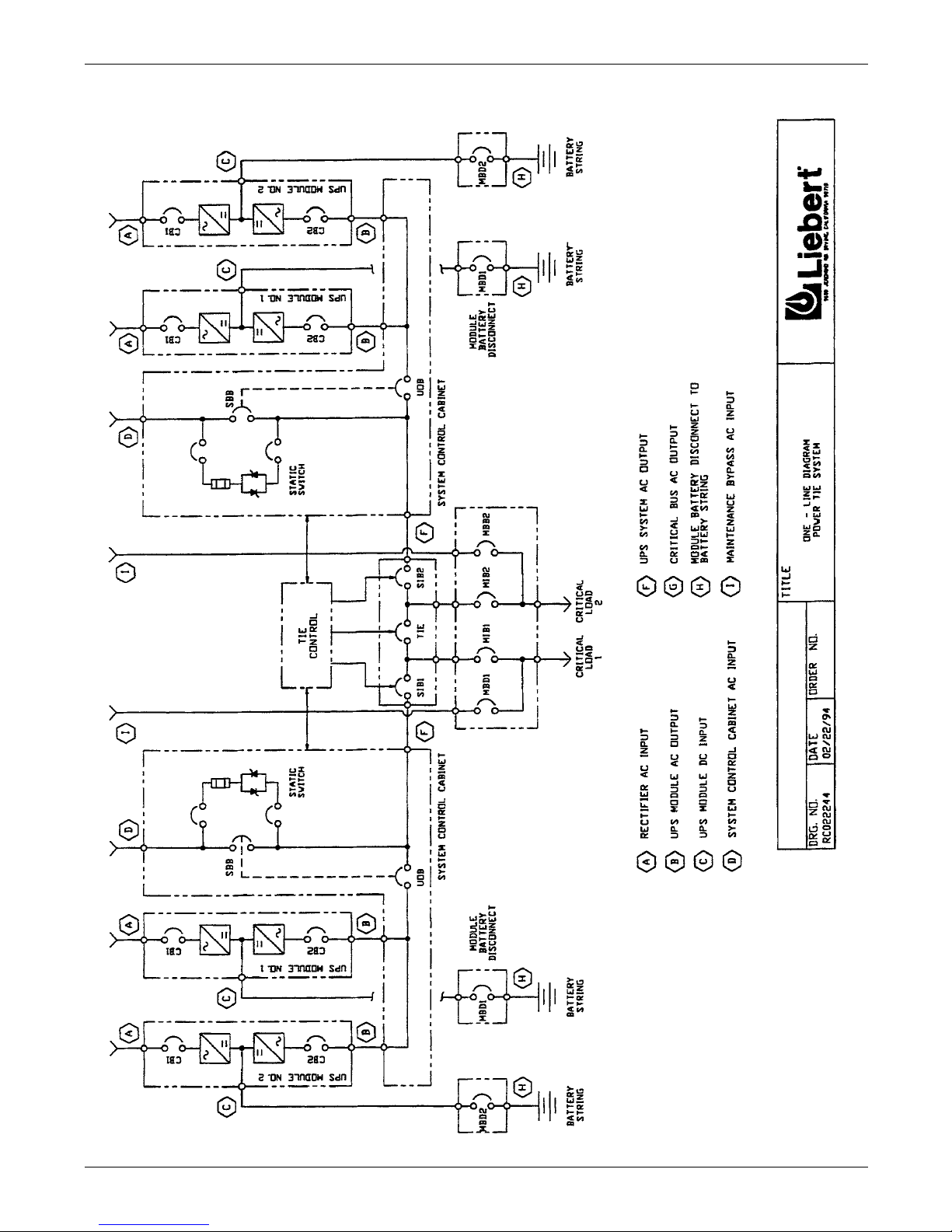
10
Figure 4 Power-Tie system one-line diagram
 Loading...