

Liebert Series 600T Installation Manual

POWER AVAILABILITY
Series 600T™ UPS
INSTALLATION MANUAL
Single Module
Three-Phase
65-225 kVA
60 Hz

The following WARNING applies to all battery cabinets supplied
with UPS systems:
INTERNAL BATTERY STRAPPING MUST BE VERIFIED BY MANUFACTURER PRIOR TO MOVING A BATTER Y CABINET.
Battery cabinets contain non-spillable batteries.
Keep units upright.
Do not stack.
Do not tilt.
Failure to heed this warning could result in smoke, fire or electric
hazard. Call 1-800-LIEBERT prior to moving battery cabinets.

INSTALLATION MANUAL
TABLE OF CONTENTS
1. SAFETY PRECAUTIONS . . . . . . . . . . . . . . . . . . . . . . . . . . . . . . . . . . . . . . . . . . . . . . . . . . . . . . . . . 1
2. INSTALLATION CONSIDERATIONS . . . . . . . . . . . . . . . . . . . . . . . . . . . . . . . . . . . . . . . . . . . . . . . 2
3. UNLOADING AND HANDLING. . . . . . . . . . . . . . . . . . . . . . . . . . . . . . . . . . . . . . . . . . . . . . . . . . . . 3
4. INSPECTIONS . . . . . . . . . . . . . . . . . . . . . . . . . . . . . . . . . . . . . . . . . . . . . . . . . . . . . . . . . . . . . . . . . . 3
4.1. External Inspections. . . . . . . . . . . . . . . . . . . . . . . . . . . . . . . . . . . . . . . . . . . . . . . . . . . . . . . 3
4.2. Internal Inspections . . . . . . . . . . . . . . . . . . . . . . . . . . . . . . . . . . . . . . . . . . . . . . . . . . . . . . . 3
5. EQUIPMENT LOCATION . . . . . . . . . . . . . . . . . . . . . . . . . . . . . . . . . . . . . . . . . . . . . . . . . . . . . . . . . 4
6. BATTERY INSTALLATION. . . . . . . . . . . . . . . . . . . . . . . . . . . . . . . . . . . . . . . . . . . . . . . . . . . . . . . . 4
6.1. Battery Safety Precautions . . . . . . . . . . . . . . . . . . . . . . . . . . . . . . . . . . . . . . . . . . . . . . . . . . 4
6.2 Battery Cabinets . . . . . . . . . . . . . . . . . . . . . . . . . . . . . . . . . . . . . . . . . . . . . . . . . . . . . . . . . . 6
6.3 Open-Rack Batteries . . . . . . . . . . . . . . . . . . . . . . . . . . . . . . . . . . . . . . . . . . . . . . . . . . . . . . . 7
7. CONFIGURING YOUR NEUTRAL AND GROUND CONNECTIONS . . . . . . . . . . . . . . . . . . . . . 7
7.1. Preferred Grounding Configuration, Isolated Power Distribution Units. . . . . . . . . . . . . . 8
7.2. Alternative Grounding Configuration, Isolated Power Distribution Units, . . . . . . . . . . . 9
7.3. Preferred Grounding Configuration, 480 or 600 VAC Input, 208VAC Output . . . . . . . . . 10
7.4. Preferred Grounding Configuration, 208 VAC Input and Output, Non-Isolated Load . . .11
7.5. Grounding Configuration, Delta Source or Impedance-Grounded Wye . . . . . . . . . . . . . . 12
7.6. Preferred Grounding Configuration with Power-Tie™ Switchgear . . . . . . . . . . . . . . . . . 13
7.7. Preferred Grounding Configuration, Battery Systems . . . . . . . . . . . . . . . . . . . . . . . . . . . 14
8. WIRING CONSIDERATIONS . . . . . . . . . . . . . . . . . . . . . . . . . . . . . . . . . . . . . . . . . . . . . . . . . . . . . 15
8.1. Power Wiring . . . . . . . . . . . . . . . . . . . . . . . . . . . . . . . . . . . . . . . . . . . . . . . . . . . . . . . . . . . . 15
8.2. Control Wiring . . . . . . . . . . . . . . . . . . . . . . . . . . . . . . . . . . . . . . . . . . . . . . . . . . . . . . . . . . . 19
8.3. Battery Wiring . . . . . . . . . . . . . . . . . . . . . . . . . . . . . . . . . . . . . . . . . . . . . . . . . . . . . . . . . . . 19
9. WIRING CONNECTIONS . . . . . . . . . . . . . . . . . . . . . . . . . . . . . . . . . . . . . . . . . . . . . . . . . . . . . . . . 20
9.1 Warnings. . . . . . . . . . . . . . . . . . . . . . . . . . . . . . . . . . . . . . . . . . . . . . . . . . . . . . . . . . . . . . . . 20
9.2 Specific Connections. . . . . . . . . . . . . . . . . . . . . . . . . . . . . . . . . . . . . . . . . . . . . . . . . . . . . . . 20
10. WIRING INSPECTION . . . . . . . . . . . . . . . . . . . . . . . . . . . . . . . . . . . . . . . . . . . . . . . . . . . . . . . . . . 21
!
WARNING
LOCATE CENTER OF GRAVITY SYMBOLS
AND DETERMINE UNIT WEIGHT BEFOR E HANDLING CABINET
If you require assistance for any reason, call the toll-free Liebert Global Services number,
1-800-543-2378. Please have the following information available:
Part Number: ________________________________________________________
Serial Number: ________________________________________________________
kVA Rating ________________________________________________________
kW Rating ________________________________________________________
Date Purchased ________________________________________________________
Date Installed ________________________________________________________
Location: ________________________________________________________
Input Voltage ________________________________________________________
Output Voltage ________________________________________________________
Battery Reserve Time: __________________________________________________
i

TABLES
Table 1. Power Wiring Terminals - Factory Supplied ..............................................................................22
Table 2. Torque Specifications...................................................................................................................22
Table 3. Field-Supplied Lugs.....................................................................................................................23
Table 310-16, NEC Allowable Ampacities of Insulated Conductors............................................................24
FIGURES
Figure 1. Preferred Grounding Configuration, 480 or 600 VAC input and output . . . . . . . . . . . . . . . . . . . 8
Figure 2. Alternative Grounding Configuration, 480 or 600 VAC input and output . . . . . . . . . . . . . . . . . 9
Figure 3. Preferred Grounding Configuration, 480 or 600 VAC input and 208 VAC output . . . . . . . . . . 10
Figure 4. Preferred Grounding Configuration, 208 VAC input and output . . . . . . . . . . . . . . . . . . . . . . . . 11
Figure 5. Preferred Grounding Configuration with Delta Source Input . . . . . . . . . . . . . . . . . . . . . . . . . . 12
Figure 6. Preferred Grounding Configuration, Power-Tie™ Systems . . . . . . . . . . . . . . . . . . . . . . . . . . . . 13
Figure 7. Preferred Battery Cabinet Grounding Configuration . . . . . . . . . . . . . . . . . . . . . . . . . . . . . . . . . 14
Figure 8. Typical One-Line Diagrams for SMS with Standard Dual Input . . . . . . . . . . . . . . . . . . . . . . . . 16
Figure 9. Typical One-Line Diagrams of SMS with optional single input. . . . . . . . . . . . . . . . . . . . . . . . . 17
Figure 10. Typical One-Line Diagrams of SMS with optional Maintenance Bypass Cabinets . . . . . . . . 18
Figure 11. Outline Drawing Single and Multi Module 65 & 80 kVA . . . . . . . . . . . . . . . . . . . . . . . . . . . . . 25
Figure 12. Outline Drawing, 100 through 225 kVA Module with SpaceSaver Top-Entry Configuration 26
Figure 13. Outline Drawing, 100 through 225 kVA Module with Standard Top & Bottom Entry . . . . . . 27
Figure 14. Bypass Transformer Cabinet, 65 & 80 kVA . . . . . . . . . . . . . . . . . . . . . . . . . . . . . . . . . . . . . . . . 28
Figure 15. Bypass Transformer Cabinet, 100-225 kVA . . . . . . . . . . . . . . . . . . . . . . . . . . . . . . . . . . . . . . . 29
Figure 16. Battery Power Pack, 65 & 80 kVA . . . . . . . . . . . . . . . . . . . . . . . . . . . . . . . . . . . . . . . . . . . . . . . 30
Figure 17. Battery Power Pack, Size A, 100-225 kVA . . . . . . . . . . . . . . . . . . . . . . . . . . . . . . . . . . . . . . . . . 31
Figure 18. Outline Drawing, 3-Breaker MBC, 65 & 80 kVA . . . . . . . . . . . . . . . . . . . . . . . . . . . . . . . . . . . 32
Figure 19. Outline Drawing, 3-Breaker MBC with Bypass Transformer, 65 & 80 kVA . . . . . . . . . . . . . . 33
Figure 20. Outline Drawing, 3-Breaker MBC, 125-350 Amps . . . . . . . . . . . . . . . . . . . . . . . . . . . . . . . . . . 34
Figure 21. Outline Drawing, 3-Breaker MBC, 450 to 800 Amps . . . . . . . . . . . . . . . . . . . . . . . . . . . . . . . . 35
Figure 22. Outline Drawing, 3-Breaker MBC, 600-800 Amps . . . . . . . . . . . . . . . . . . . . . . . . . . . . . . . . . . 36
Figure 23. Line-up Detail, 65 & 80 kVA SMS with Bypass Transformer Cabinet . . . . . . . . . . . . . . . . . . 37
Figure 24. Line-up Detail, 100-225 kVA Space Saver with Bypass Transformer Cabinet . . . . . . . . . . . . 38
Figure 25. Line-up Detail, 100-225 kVA Standard SMS with Bypass Transformer Cabinet . . . . . . . . . . 39
Figure 26. Line-up Detail, 65 & 80 kVA SMS with Battery Cabinets . . . . . . . . . . . . . . . . . . . . . . . . . . . . 40
Figure 27. Line-up Detail, 100-225 kVA Space Saver with Battery Cabinets . . . . . . . . . . . . . . . . . . . . . . 41
Figure 28. Line-up Detail, 100-225 kVA Standard SMS with Battery Cabinets . . . . . . . . . . . . . . . . . . . . 42
Figure 29. Line-up Detail, 65 & 80 kVA with 3-Breaker MBC . . . . . . . . . . . . . . . . . . . . . . . . . . . . . . . . . . 43
Figure 30. Line-up Detail, 65 & 80 kVA with Bypass Transformer and 3-Breaker MBC . . . . . . . . . . . . 44
Figure 31. Line-up Detail, 100-225 kVA Space Saver with 3-Breaker MBC . . . . . . . . . . . . . . . . . . . . . . . 45
Figure 32. Line-up Detail, 100-225 kVA Space Saver with Bypass Cabinet and 3-Breaker MBC . . . . . . 46
Figure 33. Line-up Detail, 100-225 kVA with 3-Breaker MBC . . . . . . . . . . . . . . . . . . . . . . . . . . . . . . . . . 47
Figure 34. Line-up Detail, 100-225 kVA with Bypass Transformer Cabinet and 3-Breaker MBC . . . . . 48
Figure 35. Terminal Details, 65 & 80 kVA Single Module Systems . . . . . . . . . . . . . . . . . . . . . . . . . . . . . . 49
Figure 36. Terminal Details, 100 & 125 kVA Space Saver . . . . . . . . . . . . . . . . . . . . . . . . . . . . . . . . . . . . . 50
Figure 37. Terminal Details, 150 & 225 kVA Standard SMS . . . . . . . . . . . . . . . . . . . . . . . . . . . . . . . . . . . 51
Figure 38. Terminal Details, 100 & 125 kVA Standard SMS . . . . . . . . . . . . . . . . . . . . . . . . . . . . . . . . . . . 52
Figure 39. Terminal Details, 150 & 225 kVA Standard SMS . . . . . . . . . . . . . . . . . . . . . . . . . . . . . . . . . . . 53
Figure 40. Control Connection Locations, 65 & 80 kVA . . . . . . . . . . . . . . . . . . . . . . . . . . . . . . . . . . . . . . . 5 4
Figure 41. Control Connection Locations, 100 through 225 kVA . . . . . . . . . . . . . . . . . . . . . . . . . . . . . . . . 55
Figure 42. Standard Control Wiring, Single Module System . . . . . . . . . . . . . . . . . . . . . . . . . . . . . . . . . . . 56
Figure 43. Option Wiring, Alarm Status Contacts . . . . . . . . . . . . . . . . . . . . . . . . . . . . . . . . . . . . . . . . . . . 57
Figure 44. Option Wiring, Maintenance Bypass Interlock . . . . . . . . . . . . . . . . . . . . . . . . . . . . . . . . . . . . . 58
Figure 45. Option Wiring, Remote Status Panel Interface . . . . . . . . . . . . . . . . . . . . . . . . . . . . . . . . . . . . . 59
Figure 46. Option Wiring, Remote Terminal IFM (RS-232 Communications) . . . . . . . . . . . . . . . . . . . . . 60
Figure 47. Option Wiring, SiteScan Interface . . . . . . . . . . . . . . . . . . . . . . . . . . . . . . . . . . . . . . . . . . . . . . . 61

Figure 48. Option Wiring, Customer Alarm Interface . . . . . . . . . . . . . . . . . . . . . . . . . . . . . . . . . . . . . . . . 62
Figure 49. Option Wiring, Battery Temperature Sensor . . . . . . . . . . . . . . . . . . . . . . . . . . . . . . . . . . . . . . 63
Figure 50. Option Wiring, SNMP Interface . . . . . . . . . . . . . . . . . . . . . . . . . . . . . . . . . . . . . . . . . . . . . . . . . 64
Figure 51. Option Wiring, Internal Modem . . . . . . . . . . . . . . . . . . . . . . . . . . . . . . . . . . . . . . . . . . . . . . . . . 65
Figure 52. Option Wiring, Maintenance Bypass Cabinet . . . . . . . . . . . . . . . . . . . . . . . . . . . . . . . . . . . . . . 66
Figure 53. Module Battery Disconnect, 65 through 125 kVA . . . . . . . . . . . . . . . . . . . . . . . . . . . . . . . . . . . 67
Figure 54. Module Battery Disconnect, 150 & 225 kVA . . . . . . . . . . . . . . . . . . . . . . . . . . . . . . . . . . . . . . . 68
Figure 55. Remote Status Panel, Surface Mount . . . . . . . . . . . . . . . . . . . . . . . . . . . . . . . . . . . . . . . . . . . . 69
Figure 56. Circuit Breaker Schedule, 65 through 225 kVA . . . . . . . . . . . . . . . . . . . . . . . . . . . . . . . . . . . . 70
Figure 57. Circuit Breaker Schedule, Battery Cabinets, 65 to 500 kVA . . . . . . . . . . . . . . . . . . . . . . . . . . 71
Figure 58. Circuit Breaker Schedule, Maintenance Bypass Cabinet, 65 through 225 kVA . . . . . . . . . . . 72
iii


INSTALLATION
1. SAFETY PRECAUTIONS
Read this manual thoroughly, paying special
attention to the sections that apply to you, before
working with the UPS. Retain this manual for
use by installing personnel.
Under typical operation and with all UPS doors
closed, only normal safety precautions are
necessary. The area around the UPS system should
be kept free from puddles of water, excess
moisture, or debris.
Special safety precautions are required for
procedures involving handling, installation, and
maintenance of the UPS system or the battery.
Observe all safety precautio n s in this manual
before handling or installing the UPS system.
Observe all precau t ion s in the Operation and
Maintenance Manual, before and during
performance of all maintenance proced ures.
Observe all battery safe ty precautions before
working on or near the battery.
This equipment contains several circuits that
are energized with high voltage. Only test
equipment designated for troubleshooting should
be used. This is particularly true for oscilloscopes.
Always check with an AC and DC voltmeter to
ensure safety before making contact or using tools.
Even when the power is turned Off, dangerously
high potentials may exist at the capacitor banks
and at the batteries.
when performing the actions described by that
text.
A Danger signals immediate hazards resulting in
severe personal injury or death. For example:
DANGER
A DANGER SIGNALS IMMEDIATE
HAZARDS WHICH WILL RESULT IN
SEVERE PERSONAL INJURY OR DEATH.
A Warning signals the presence of a possible
serious, life-threatening condition. For example:
WARNING
LETHAL VOLTAGES MAY BE PRESENT
WITHIN THIS UNIT EVEN WHEN IT IS
APPARENTLY NOT OPERATING.
OBSERVE ALL CAUTIONS AND
WARNINGS IN THIS MANUAL. FAILURE
TO DO SO COULD RESULT I N SERIOUS
INJURY OR DEATH. D O NOT WO RK ON O R
OPERATE THIS EQUIPMENT UNLESS
YOU ARE FULLY QUALIFIED TO DO SO!!
NEVER WORK ALONE.
A Caution indicates a condition that could
seriously damage equipment and possibly injure
personnel. For example:
ONLY qualified service personnel should
perform maintenance on the UPS system.
When performing maintenance with any part of
the equipment under power, service personnel and
test equipment should be standing on rubber mats.
The service personnel should wear insulat ing
shoes for isolation from direct contact with the
floor (earth ground).
Unless all power is removed from the equipment,
one person should never work alone. A second
person should be standing by to assist and
summon help in case an accident should occur.
Four types of messages are used throughout the
manual to stress important text. Carefully read the
text below each Danger, Warning, Caution, and
Note and use professional sk ills and prudent care
Liebert Series 600T UPS, 65-225 kVA, Single Module 1
CAUTION
Extreme care is necessary when removing
shoring braces. Do not strike the cabinet
with hammers or other tools.
A Note emphasizes important text. If the note is
not followed, equipment could be damaged or may
not operate properly. For example:
NOTE
If the UPS system has a blown fuse, the
cause should be determined before you
replace the fuse. Contact Liebert Global
Services.

2. INSTALLATION CONSIDERATIONS
Install your Series 600T UPS in accordance
with the submittal drawing package and the
following procedures.
A Liebert authorized representative must
perform the initial system check-out and startup to ensure prop er sy st e m ope rat ion .
Equipment warranties will be voided unless
system start-up is performed by a Liebert
authorized representative. Contact your local
Liebert sales representative or Liebert Global
Services at 1-800-543-2378 to arrange for
system start-up.
CAUTION
Read this manual thoroughly before
attempting to wire or operate the unit.
Improper installation is the most
significant cause of UPS start-up
problems.
Do not install this equipment near gas
or electric heaters. It is preferable to
install the UPS in a restricted location
to prevent access by unauthorized
personnel.
1. Proper planning will speed unloading,
location, and connection of the UPS. Refer
to Figures 11 through 58 and the Site
Planning Data (Appendix A).
2. Be certain that the floor at the final
equipment location and along the route
(inside the facility) to the installation site
can support the cabinet weight an d the
weight of any material handling
equipment. The UPS modules can weigh
up to two tons. The battery cabinets weigh
between 2300 and 5000 pounds each.
4. Refer to information later in this manual
regarding the optional Battery Cabinet(s),
Maintenance Bypass Cabinets,
Panelboards and Switchboa rds. Observe
all battery safety precautions when
working on or near the battery.
5. Use the shortest output distribution cable
runs possible, consistent with logical
equipment arrangements and with
allowances for future additions if planned.
6. Recommended ambient operating
temperature is 25C (77F). Relative
humidity must be less than 95%, noncondensing. Note that room ventilation is
necessary, but air conditioning may not be
required. Maximum ambient operating
temperature for the UPS and switchgea r is
40C (104F) without derating. The
batteries should not exceed 25 C (77F). At
elevations above 4,000 feet (1219 meters)
temperature derating may be required for
full power output (consult your Liebert
sales representative).
7. Even though your Li ebert UPS unit is 92.5
to 94% efficient, the heat output is
substantial. For more specific information,
see the Site Planning Data (Appendix A).
Be sure environmental conditioning
systems can accommodate this BTU load,
even during utility outages.
8. The installer should attempt to balance the
load between the three out put phases . The
UPS will operate safely with an unbalanced load, but will give optimum performance if the three output phases are
loaded within 20 percent of each other.
3. Plan the routing to ensure that the unit
can move through all aisle ways, doorways,
and around corners without risking
damage. If the modules and batteries must
be moved by elevator, check the size of the
door openings and the weight-carrying
capacity of the elevator.
2 Installation Manual

3. UNLOADING AND HANDLING
4. INSPECTIONS
Because the weight distribution in each UPS and
ancillary cabinet is uneven, use extreme care
during handling and transport. Your installation
may also include Battery Cabinets, a Bypass
Transformer Cabinet and a Maintenance Bypass
Cabinet, Panelboard or Switchboard.
WARNING
EXERCISE EXTREME CARE WHEN
HANDLING UPS CABINETS TO AVOID
EQUIPMENT DAMAGE OR INJURY TO
PERSONNEL. THE UPS MODU LE CAN
WEIGH UP TO TWO TONS. THE BATTERY
CABINETS WEIGH UP TO 5100 POUNDS.
THE UPS MODULES ARE HEAVIER IN
THE BACK THAN THE FRONT BECAUSE
OF THE WEIGHT OF THE MAGNETICS.
LOCATE CENTER OF GRAVITY SYMBOLS
BEFORE HANDLING CABINET. TEST LIFT
AND BALANCE THE CABINET BEFORE
TRANSPORTING. MAINTAIN MINIMUM
TILT FROM VERTICAL AT ALL TIMES.
4.1. External Inspections
1. While the UPS system is still o n the truck,
inspect the equi p men t and shi ppin g
container(s) for any signs of damage or
mishandling. Do not attempt to install the
system if damage is apparent. If any damage is
noted, file a damage claim with the shipping
agency within 24 hours and contact Liebert
Global Services at 1-800-543-2378 to inform
them of the damage claim an d the cond it ion of
the equipment.
2. Locate the bag co ntaining the keys fo r the front
access door. The bag is attached to the cabinet.
3. Compare the contents of the shipment with the
bill of lading. Report any missing items to the
carrier and to Liebert Global Services
immediately.
4. Check the nameplate on the cabinet to verify
that the model number corresponds with the
one specified. Record the model number and
serial number in the front of this installation
manual. A record of this information is
necessary should servicing become required.
WARNING
INTERNAL BATTERY CABINET
STRAPPING MUST BE VERIFIED BY
MANUFACTURER PRIOR TO MOVING
THIS UNIT.
THIS UNIT CONTAINS NON-SPILLABLE
BATTERIES. KEEP UNIT UPRIGHT. DO
NOT STACK. DO NOT TIP.
FAILURE TO HEED THIS WARNING
COULD RESULT IN SMOKE, FIRE OR
ELECTRICAL HAZARD. CALL 1-800LIEBERT PRIOR TO RELOCATING
BATTERY CABINET (AFTER INITIAL
INSTALLATION).
4.2. Internal Inspections
1. Verify that all items have been received.
2. If spare parts were ordered, verify arrival.
3. Open doors and remove cabi net panels to check
for shipping damage to internal components.
4. Check for loose connections or unsecured
components in the cabinet(s).
5. Check for installation of circuit breaker line
safety shields. There should be no exposed
circuit breaker terminals when the cabinet
doors are opened.
6. Remove any orange shipping braces or
brackets fr om the transformers.
7. Check for any unsafe condition that may be a
potential safety hazard.
Liebert Series 600T UPS, 65-225 kVA, Single Module 3

5. EQUIPMENT LOCAT ION
1. Handle cabinet(s) in accordance with WARNINGS in Section 3. Use a suitable material
handling device to move each cabinet to its
final location. Exercise extreme care
because of the uneven weight distribution. Carefully lower the cabinets to the floor
and position them for reconnection, if applicable.
2. Verify that the UPS system is installed in a
clean, cool and dry location. Observe the
location of overhead water lines for fire
sprinkler systems. Avoid placing the UPS and
related equipment directly under water lines
or within range of a sprinkler head.
3. Installation and serviceability will be easier if
adequate access is provided on all sides of the
equipment, but only front access is required.
a. Verify that there is adequate clearance to
open cabinet doors (4 feet is recommended ).
See drawings and local codes.
b. V erify that there is adequate area in fron t of
circuit breakers to perform maintenance.
Check installation drawings for location of
breakers. Check with local codes.
c. Verify that there is adequate clearance
above all cabinets to allow exhaust air to
flow without restriction (2 feet minimum,
unobstructed).
4. Connec t the cabinets, internal cables and bus
bars, if applicable.
6. BATTERY INSTALLATION
6.1. Battery Safety Precautions
Battery installation and servicing should be
performed or supervised by personne l
knowledgeable of batteries and the required
precautions. Keep unauthorized personnel away
from batteries.
Be sure to observe the grounding recommendations
in Section 7 when installing batteries. When
replacing batteries, use the same number and type
of batteries.
CAUTION
Lead-acid batteries contain hazardous
materials. Batteries must be ha ndled,
transported, and recycled or discarded in
accordance with federal, state, and local
regulations. Because lead is a toxic
substance, lead-acid batteries should be
recycled rather than discarded.
Do not open or mutilate the battery or
batteries. Released electrolyte is harmful
to the skin and eyes. It may be toxic. Do
not dispose of battery or batteries in a fire.
The battery may explode.
A battery can present a risk of electrical
shock and high short-circuit current. The
following precautions should be observed
when working on batteries:
1. Remove watches, rings, or other metal
objects.
2. Use tools with insulated handles.
3. Wear rubber gloves and boots.
4. Do not lay tools or metal parts on top of
batteries.
5. Disconnect charging source prior to
connecting or disconnecting battery
terminals.
6. Determine if the battery is inadvertently grounded. If it is inadvertently
grounded, remove source of ground.
Contact with any part of a grounded
battery can result in electrical shock.
The likelihood of such shock will be
reduced if such grounds are removed
during installation and maintenance.
Lead-acid batteries can present a risk of
fire because they generate hydrogen gas.
The following procedures should be
followed:
1. DO NOT SMOKE when near batterie s.
2. DO NOT cause flame or spark in
battery area.
3. Discharge static electricity from body
before touching batteries by first
touching a grounded metal surface.
4 Installation Manual

BATTERY SAFETY PRECAUTIONS IN
FRENCH PER CSA REQUIREMENTS
INSTRUCTIONS IMPORTANES
CONCERNANT LA SÉCURITÉ
CONSERVER CES INSTRUCTIONS
AVERTISSEMENT
DES PIECES SOUS ALIMENTATION SERONT
LAISSEES SANS PROTECTION DURANT CES
PROCEDURES D'ENTRETIEN. UN
PERSONNEL QUALIFIE EST REQUIS POUR
EFFECTUER CES TRAVAUX.
LES FUSIBLES A C.C. DE LA BATTERIE
D'ACCUMULATEURS OPERENT EN TOUT
TEMPS A LA TENSION NOMINALE. LA
PRESENCE D'UN FUSIBLE A C.C. BRULE
INDIQUE UN PROBLEME SERIEUX. LE
REMPLACEMENT DE CE FUSIBLE, SANS
AVOIR DETERMINE LES RAISONS DE LA
DEFECTUOSITE, PEUT ENTRAINER DES
BLESSURES OU DES DOMMAGES SERIEUX A
L'EQUIPEMENT. POUR ASSISTANCE,
APPELER LE DEPARTEMENT DE SERVICE A
LA CLIENTELE DE LIEBERT.
DANGER
Les accumulateurs plomb-acide contiennent de la
matière comportant un certain risque. Les
accumulateurs doivent être manipulés, transportés
et recyclés ou éliminés en accord avec les lois
fédérales, provinciales et locales. Parce que le
plomb est une substance toxique, les
accumulateurs plomb-acide devraient être recyclés
plutôt qu'éliminés.
Il ne faut pas brûlé le ou les accumulateurs.
L'accumulateur pourrait alors explosé.
Il ne faut pas ouvrir ou endommager le ou les
accumulateurs. L'électrolyte q u i pourrait s'en
échapper est dommageable pour la peau et les
yeux.
Un accumulateur représente un risque de choc
électrique et de haut courant de court-circuit.
Lorsque des accumulateurs sont manipulés, les
mesures préventives suivantes devraient être
observées:
1. Retirer toutes montre, bagues ou autres objets
métalliques.
2. Utiliser des outils avec manchon isolé.
3. Porter des gants set de s bo tte s deca utchouc.
4. Ne pas déposer les outils ou les pièces
métalliques sur le dessus des accumulateurs.
5. Interrompre la source de charge avant de
raccorder ou de débrancher les bornes de la
batterie d'accumulateurs.
6. Déterminer si l'accumulateur est mis à la terre
par erreur. Si oui, défaire cette mise à la terre.
Tout contact avec un accumulateur mis à la
terre peut se traduire en un ch oc élec trique. La
possibilitié de tels chocs sera réduite si de
telles mises à la terre sont débranchées pour la
durée de l'installation ou de l'entretien.
Les accumulateurs plomb-acide présentent un
risque d'incendie parce qu'ils génèrent des gaz à
l'hydrogène. Les procédures suivantes devront être
respectées.
1. NE PAS FUMER lorsque près des
accumulateurs.
2. NE PAS produire de flammes ou d'étincelles
près des accumulateurs.
3. Décharger toute électricité statique présente
sur votre corps avant de toucher un
accumulateur en touchant d'abord une surface
métallique mise à la terre.
DANGER
L'électrolyte est un acide sulfurique dilué qui est
dangereux au contact de la peau et des yeux. Ce
produit est corrosif et aussi conducteur electrique.
Les procédures suivantes devront être observées:
1. Porter toujours des vêtements protecteurs
ainsi que des lunettes de protection pour les
yeux.
2. Si l'électrolyte entre en contact avec l a peau,
nettoyer immédiatement en rinçant avec de
l'eau.
3. Si l'électrolyte entre en contact avec les yeux,
arroser immédiatement et généreusement avec
de l'eau. Demander pour de l'aide médicale.
4. Lorsque l'électrolyte est renversée, la surface
affectée devrait être nettoyée en utilisant un
agent neutralisant adéquat. Une prati que courante est d'utiliser un mélange d'appro ximativement une livre (500 grammes) de
bicarbonate de soude dans approximativement
un gallon (4 litres) d'eau. Le mélange de bicarbonate de soude devra être ajouté jusqu'à ce
qu'il n'y ait plus apparence de réaction
(mousse). Le liquide résiduel devra être nettoyé à l'eau et la surface concernée devra être
asséchée.
Liebert Series 600T UPS, 65-225 kVA, Single Module 5

6.2 Battery Cabinets
Optional battery cabinets are available from
Liebert and other qualified vendors. Consult your
submittal package for details.
The same model battery cabinet may be paralleled
in multiple cabinet strings for additional capacity.
Battery capacity (in minutes) a t your installation
will depend on cabinet model, number of cabinets,
and amount of critical load on the UPS.
1. Handling. The Battery Cabinet weighs up to
5100 pounds. Fork lift slots are provided in the
base of 100-225 kVA cabinets for easy
handling. Fork lift forks or a pallet jack can be
used between the casters of the 65 and 80 kVA
battery cabinets.
2. Cabinet Inspection. Remove all panels and
visually inspect the batteries, bus connections,
and cabinet for any damage. If any foam blocks
were placed between shelves to restrain
movement during shipment, remove them now.
Exercise caution; voltage is present
within the Battery Cabinet even before
installation. If there are signs of damage, do
not proceed. Call Liebert Global Services at 1800-542-2378.
3. Battery Storage. The batteries used in the
Battery Cabinet retain their charge well. The
batteries can be stored for up to six months
without any appreciable deterioration. Selfdischarge rate of the ba tteries is app roximately
3% per month when the batteries are stored in
temperatures of 15°C to 25°C (59°F to 77°F). If
the Battery Cabinet must be stored for longer
than six months, contact Liebert Global
Services.
4. Installation. The Battery Cabinet(s) can be
located conveniently to the left side of the 65225 kVA UPS module. The front-access-onlydesign eliminates side and rear service
clearance requirements.
7. Service Clearance. Allow fron t acc es s to the
Battery Cabinet at all times for maintenance
and servicing. Electrical codes require that the
Battery Cabinet be installed with no less than
3 feet (1 meter) of clearance at the front of the
cabinet when operating. Side and rear pan els
do not require service clearance.
8. Side Panels. Remove protective side panels to
connect battery cabinets together. Do not
remove the shield plate, explained below.
9. Shield Plate. The shield plate in 125 kVA
Battery Cabinets should be on the side toward
the UPS system. Mov e the shie ld if req uir ed by
your Battery Cabinet location.
10. Cables. Cables may be run between battery
cabinets through cutouts in the top of the
cabinets, eliminating the need for external
conduit runs. Route cables before moving
cabinets into fi nal position for bolting
together. Remove top panels for access. Refer
to Figures 16 and 17 or your submittal
drawings for instructions on wiring cabinets in
parallel.
11. Grounding. The battery cabinets have ground
studs near the bus bar connections. Use an
equipment grounding conductor to connect the
lugs of the cabinets to gether and to connect the
cabinets to the ground bus bar in the UPS
module.
CAUTION
Cables between batteries and modules
should be run in matched pairs, positivewith-negative. Grouping like-polarity
cables together (i.e. positive-with-positive
and negative-with-negative) can cause
stress or damage to the cables, conduit or
buswork.
5. Re-Installation. If it later becomes necessary
to move the Battery Cabinet to another
location, contact Lieb ert Global Services to
inspect the internal battery hold-down straps.
6. Environment. Locate the Battery Cabinet in
a clean, dry environment. Recommended
temperature range for optimum performance
and lifetime is 20-25°C (68-77°F).
6 Installation Manual

6.3 Open-Rack Batteries
When batteries other than Liebert Battery
Cabinets are used, a remote battery disconnect
switch with overcurrent protection is required per
the National Electrical Code. Refer to Figures 53
and 54. Contact your Liebert sales representative.
1. Install battery racks/cabinets and batteries per
manufacturer's installation and maintenance
instructions.
2. Verify battery area has adequate ventilation
and battery operating temperature complies
with manufacturer's specification.
3. Ensure that battery racks are properly
grounded according to code requirements in
your area.
If you have any questions concer ning batteries,
battery racks, or accessories, contact Liebert
Global Services at 1-800-543-2378.
CAUTION
Cables between batteries and modules
should be ru n in matche d pairs, positivewith-negative. Grouping like-polarity
cables together (i.e. positive-with-positive
and negative-with-negative) can cause
stress or damage to the cables, conduit or
buswork.
7. CONFIGURING YOUR NEUTRAL AND
GROUND CONNECTIONS
Improper grounding is the largest single cause of
UPS installation and start-up problems. This is not
an easy subject, since grounding techniques vary
significantly from site to site, depending on several
factors. The questions you should ask are:
• What is the configuration of the input power
source? Most of the recommended schemes f or
UPS grounding require grounded-wye service. The UPS system requires a bypass neutral for sensing and monitoring the quality of
the bypass input. If the building service is
ungrounded delta or corner-grounded delta,
contact your Liebe rt re pres ent ati ve to ens ure
your system includes the Artificial Neutral or
Isolated Neutral kit.
• Does the system have a bypass isolation
transformer? Systems with 480 VAC (or 600
VAC) input and 208 VAC output require a
bypass isolation transformer. In some cases,
it may be necessary to treat that transformer
as a “separat ely derived source” with its own
grounding electrode. See page 10 for details.
• What are the UPS input and output voltages?
Systems with 480 VAC input and output have
significantly different needs than systems
with 480/208 VAC or 208/208 VAC.
• What is the connected load? Does the critical
load consist of one or more Power Distribution Units (PDUs)? Do the PDUs have isolation transformers?
The following sections discuss recommended
grounding procedures for various system
configurations.
Liebert Series 600T UPS, 65-225 kVA, Single Module 7
NOTE
Some UPS modules are equipped with
input isolation transformers. However,
these transformers have no effect upon any
system grounding considerations. These
modules will be grounded exactly as shown
in the following examples.

GROUNDING
ELECTRODE
PER NEC 250-24
Figure 1. Preferred Grounding Configuration, 480 or 600 VAC input and output
7.1. Preferred Grounding Configuration,
480 or 600 VAC Input and Output,
Isolated Power Distribution Units,
Wye-Connected Service
One of the most-common configurations of the
Series 600T UPS is the Single Module System with
480 VAC input, 480 VAC output, and a connected
load consisting of multiple Power Distribution
Units (PDUs) with isolation transformers in the
PDUs to produce 208 VAC. For Canadian
customers, the UPS modules usually have 600 V AC
input and output. The same principles apply if the
connected load is an isolation transformer feeding
various loads. Figure 1 above shows a typical
installation.
Notice that the UPS module main input and
bypass input are connected to a grounded-wye
service. In this configuration, the UPS module is
not considered a separately derived source. The
UPS module output neutral is solidly connected to
the building service neutral, which is bonde d to the
grounding conductor at the service entrance
equipment
The isolation transformers in the PDUs are
considered a separately derived source. Therefore
the PDU neutral should be bonded to the PDU
grounding conductor and connected to a local
grounding electrode in compliance with NEC 250-
26.
Advantages of this configuration include:
• A measure of common-mode noise attenuation, since the isolation (common-mode rejection) occurs as close to the load as practical
(i.e. at the PDU).
• The UPS module can be located remotely
from the PDU without compromising common-mode noise performance.
• By using UPS modules with 480 VAC input
and output and creating 208 V AC at the PDU,
smaller and less costly power feeders can be
used and less voltage drop (as a percent of
nominal) occurs.
NOTE
Impedance-grounded wye sources must be
grounded in accordance with Section 7.5.
8 Installation Manual

Figure 2. Alternative Grounding Configuration, 480 or 600 VAC input and output
7.2 Alternative Grounding
Configuration, 480 or 600 VAC Input
and Output, Isolated Power
Distribution Units, Wye-Connected
Service
This configuration is similar to that shown in
Section 7.1, except that the service entrance
neutral is not brought into the UPS module. In this
configuration, the UPS output transformer is
considered a separately derived source. The UPS
module neutral is bonded to the UPS ground,
which is connected to a local groundi ng electrode in
accordance with NEC 250-26.
Please note that this configuration represents a
price/performance trade-off. Whenever the UPS
module transfers to or from bypass, two AC sources
(input and bypass) are briefly connected together
and circulating current must flow. In the previous
configuration, the current flows through the
neutral conductor. In this configuration, the
current flows through the ground path, possibly
tripping ground fault interruptors (GFIs) and
distorting the bypass waveform reference. Proper
adjustment of ground fault interrupters is
necessary to avoid unwanted tripping.
This configuration is reserved for those
applications which meet all the following criteria:
• The facility has Wye-connected service
• The module rectifier input and bypass input
are fed from the same source
• The connected load is strictly 3-wire (such as
one or more PDUs ) an d doe s no t require a
neutral from the UPS
• Special precautions are taken to prevent tripping the ground fault interruptors. The time
delay should be set to at least 30 cycles to prevent tripping when the UPS performs a
transfer or retransfer operation.
CAUTION
Failure to properly set the ground fault
interruptors could cause loss of power to
the critical load.
Liebert Series 600T UPS, 65-225 kVA, Single Module 9

C 250
LOCAL GROUNDING
ELECTRODE
PER NEC 250-30
GROUNDING
ELECTRODE
PER NE
-24
Figure 3. Preferred Grounding Configuration, 480 or 600 VAC input and 208 VAC output
7.3. Preferred Grounding Configuration,
480 or 600 VAC Input, 208VAC
Output, and Isolated Bypass
Another configuration in this power range is the
Single Module System with 480 or 600 VAC input,
208 VAC output, a Bypass Isolation Transformer
and a connected load consisting of multiple
distribution panelboards or switchboards. Figure 3
above shows a typical installatio n.
The Bypass Transformer provides isolation and
steps down the voltage to the bypass inputs. The
Bypass T ra ns former and t he UPS modul e toget her
constitute a separately derived system, since there
is no direct electrical connection bet ween the input
(service entrance) circuit conductors and the
output circuit conductors.
NOTE
The illustration above shows a wyeconnected source, but the same grounding
scheme would apply for a delta source at
the service entrance.
The bonding of the neutral to the grounding
conductor can theoretically be done at either the
UPS module or the Bypass Transformer. However,
we recommend bonding at the Bypass Transformer
because the UPS module will sometimes be
powered down for maintenance and its output
transformer will be out of the circuit. The neutral
should be bonded to ground and a local grounding
electrode should be installed at the Bypass
Transformer, per NEC 250-30.
Features of this configuration include:
• The UPS receives its bypas s neutral from the
Bypass Transformer
• The output is isolated from the input circuit
conductors, and
• Some amount of common-mode noise attenuation can be obtained for sensitive loads if the
UPS module and Bypass Transformer are
located close to sensitive loads.
10 Installation Manual

GROUNDING
ELECTRODE
PER NEC 250-24
Figure 4. Preferred Grounding Configuration, 208 VAC input and output
7.4. Preferred Grounding Configuration,
208 VAC Input and Output, NonIsolated Load, Wye-Connected
Service
A few applications in this power range have 208
VAC input and output, and a connected load
consisting of multiple Power Distribution Units
(PDUs), panelboards, switchboards or other items
of load equipment which do not have isolation
transformers.
Notice in Figure 4 above that the UPS module
main input and bypass input are connected to a
grounded-wye service. In this configura tion, the
UPS module is not considered a separately d erived
source.
The UPS module output neutra l and the load
neutral are solidly connected to the building
service neutral, which is bonded to th e grounding
conductor at the service entrance equipment.
This arrangement is typical for systems with 208
VAC input and output. However, it does not
provide any isolation or common-mode noise
attenuation for sensitiv e loa d s.
Liebert Series 600T UPS, 65-225 kVA, Single Module 11

GROUNDING
0
ELECTRODE
PER NEC 250-24
LOCAL
GROUNDING
ELECTRODE
PER NEC 250-30
LOCAL
GROUNDING
ELECTRODE
PER NEC 250-30
GROUNDING
ELECTRODE
PER NEC 250-24
Figure 5. Preferred Grounding Configuration with Ungrounded Delta Source Input (top) and
Corner-Grounded Delta (bottom)
7.5. Grounding Configuration, 480 or 600
VAC Input and Output, Delta Source
or Impedance-Grounded Wye
As previously mentioned, Series 600T UPS
modules require a bypass input neutral for sensing
and monitoring. With a wye-connected input
source, the installer should always connect the
building service neutral to the module output
neutral to achieve this. When the building service
is delta-connected, however, the installer must
take special steps to ensure reliable UPS
functioning.
If building service is ungrounded delta (and there
is no intent to operate with one corner of the delta
grounded, either on purpose or accidentally), the
UPS requires the Series 600T Artificial Neutral
Kit for proper operation. This kit uses a resistor
network to create a reference point for the bypass
input. In this case, the UPS output neutral must be
bonded to the UPS ground. See Figure 5 above.
If the building service is corner-grounded delta or
an impedance-grounded wye, the UPS requires the
Series 600T Isolated Neutral Kit. This kit uses
control isolation transformers to create a reference
point. For this application, the UPS output neutral
must not be bonded to the UPS ground.
LOCAL
GROUNDING
ELECTRODE
PER NEC 250-3
12 Installation Manual

GROUNDING
ELECTRODE
PER NEC 250-24
GROUNDING
ELECTRODE
PER NEC 250-24
Figure 6. Preferred Grounding Configuration, Power-Tie™ Systems
7.6. Preferred Grounding Configuration,
480 or 600 VAC Input and Output,
with Power-Tie™ Switchgear
Single Module Systems c an be used wit h Power-T ie
switchgear to provide dual critical load busses. The
Power-Tie switchgear permits transferring critical
loads from one critical bus to the other so that one
UPS module and associated breakers can be deenergized for maintenance. Certain configurations
of Power-T ie equipment also permit th e operator to
continuously parallel the output of the UPS
modules.
In tied systems, each UPS module must have its
neutral solidly connected to its own building
service neutral and to the Power-Tie switchgear
neutral. See Figure 6 above.
NOTE
It is essential to run a neutral connection
between the tie switchgear and both UPS
modules as shown in the illustration above.
Liebert Series 600T UPS, 65-225 kVA, Single Module 13

GROUNDING
ELECTRODE
PER NEC 250-24
Figure 7. Preferred Battery Cabinet Grounding Configuration
TO OUTPUT
DISTRIBUTION
7.7. Preferred Grounding Configuration,
Battery Systems
Large, open-rack battery systems are normally
either locally grounded or left ungrounded,
depending on local code requirements.
Battery cabinet systems, on the other hand, should
be grounded to the UPS ground bus bar. Figure 7
above illustrates how a simple one-cabinet system
would be grounded. For systems with multiple
cabinets, the same configuration would apply.
However , for simplicity the installer can connect all
the battery cabinet grounds together and run a
single ground conductor (in the same conduit as
the phase conductors) to the UPS ground.
14 Installation Manual

8. WIRING CONSIDERATIONS
8.1. Power Wiring
Refer to Site Planning Data (Appendix A) and the
installation drawings. Determine AC currents for
your system based on kVA, kW, voltage, and
options. Also refer to equipment nameplate for the
model number, rating, and voltage. For wire
termination data, refer to Tables 1-3.
1. Power wiring -- rectifier input, bypass input,
UPS output, and battery cables -- must be run
in individual, separate conduit or cable tray.
Refer to the Outline and Terminal Details
drawings (Figures 11-13 and 35-39) for location
of the various power connections within the
UPS.
CAUTION
Power and control wiring must be
separated!
2. Observe local, state and national electrical
codes. Verify utility power and its overcurrent
protection rating will accommodate the UPS
input rating, including battery recharging.
3. A safety ground wire must be run from
building ground to ground point in the UPS
Module Cabinet, the Battery Cabinet and the
Power-Tie™ switchgear cabinet. See Sections
7.1 through 7.7. The g rounding conducto r shall
comply with the following conditions of
installation:
a. The insulated grounding conducto r must be
sized in accordance with the NEC and local
codes. It must be green (with or without
yellow stripes) and be installed as part of
the branch circuit that supplies the unit or
system.
connected to earth ground at the service
equipment.
4. Observe clockwise phase rotation of all power
wiring. Phase A leads Phase B leads Phase C.
A qualified electrician should check the phase
rotation.
5. Power cables must be rated for less than 2 volts
line drop at maximum rated system current.
6. Use 75°C copper wire. Select wire size based on
the ampacities in Table 310-16 and associated
notes of the National Electrical Code (NFPA
70) reprinted on page 24 of this manual.
CAUTION
The weight of power cables must be
adequately supported to avoid stress on
bus bars and lugs. The following
restraining method is recommended to
both to support cable weight and control
cable movement during external fault
conditions: Wrap line cables together at 6
inches and 12 inches from the terminals
with 5 wraps of 3/8 inch nylon rope or
equivalent (tensile strength of 2000
pounds). Support remainder of cable w ith
5 wraps every 6 inches or 1 wrap every 1
inch.
7. If site equipment includes a backup generator
and automatic transfer switch(es), consult the
manufacturers of those devices for information
on sizing and interfacing to the UPS system.
8. The installing contractor can remove the access
plates from the top left or top right sides of the
UPS in order to cut entry hole s for conduit . For
units with bottom-entry cable access, there is a
separate (third) access plate in the base of the
unit, under the cable access wireway.
b. The grounding conductor described abo ve is
to be grounded to earth at th e se rvic e equi pment or, if supplied by a separately derived
system, at the supply transformer or motorgenerator set in accordance with the
instructions in Section 7 of this Manual.
c. The attachment-plug receptacles in the
vicinity of the unit or system are al l to be of
a grounding type, and the grounding conductors serving these receptacles are to be
Liebert Series 600T UPS, 65-225 kVA, Single Module 15
CAUTION
After cutting holes in the access plates, be
certain that no foreign matter (metal
shavings, sawdust, insulation or wire
fragments, etc.) remains inside the UPS.
Likewise be certain to block any “extra”
holes in the plates through which foreign
matter could later enter the UPS.
CB3
CB3
CB1
CB1
Standard SMS, with 208/208, 480/480 or 600/600
Standard SMS, with 208/208, 480/480 or 600/600
VAC input/output.
VAC input/output.
CB2
CB2
Bypass
Isolation
Xfmr
CB3
CB3
Input Iso
Input Iso
Transformer
Transformer
CB1
CB1
SMS with input isolation transformer and 208/208,
SMS with input isolation transformer and 208/208,
480/480 or 600/600 VAC input/output.
480/480 or 600/600 VAC input/output.
CB3
CB2
CB2
CB1
CB2
600/208 VAC module with external bypass
isolation transformer.
Bypass
Isolation
Xfmr
CB3
Input Isolation
Transformer
CB1
CB2
480/208 or 600/208 VAC module with both
internal input isolation transformer and external
bypass isolation transformer.
Figure 8. Typical One-Line Diagrams for SMS with Standard Dual Input
16 Installation Manual

CB3
Input Isolation
Transformer
CB3
CB1
CB2
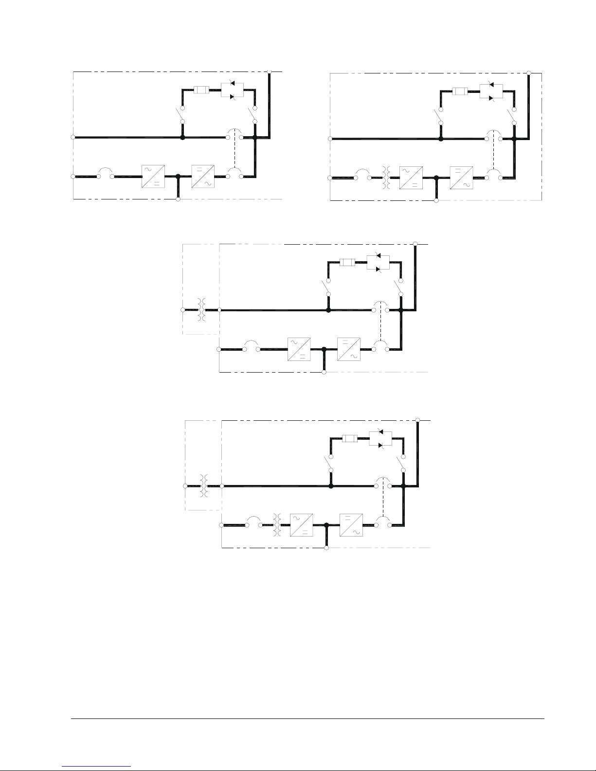
Standard single-input SMS with 208/208, 480/480
or 600/600 VAC input/output.
Internal
Bypass
Isolation
Xfmr
CB3
CB1
CB2
480/208 VAC single-input SMS with bypass
isolation transformer. Single-input modules are
not available with both byp ass and in put isolation
transformers.
CB1
CB2
Single-input SMS with input isolation tra nsformer
and 208/208, 480/480 or 6 00/ 600 VAC input/output.
External
Bypass
Isolation
Transformer
CB3
CB1
CB2
600/208 VAC single-input SMS with bypass
isolation transformer. Single-input modules are
not available with both byp ass and in put isolation
transformers.
Figure 9. Typical One-Line Diagrams of SMS with optional single input.
Liebert Series 600T UPS, 65-225 kVA, Single Module 17

MBB
MBB
MIB
CB3
CB1
CB2
CB1
2-breaker Maintenance Bypass Cabinets for standard (left) and single-input (right) modules.
MBB
BIB
CB1
MIB
CB3
CB2
RIB
CB1
3-breaker Maintenance Bypass Cabinets for standard (left) and single-input (right) modules.
MIB
CB3
CB2
MBB
MIB
CB3
CB2
MBB
MIB
CB3
CB2
BYPASS
ISO XFMR
(OPT.)
CB1
BIB
MBB
CB3
CB2
MIB
RIB
CB1
BYPASS
ISO XFMR
(OPT.)
BIB
3-breaker and 4-breaker Maintenance Bypass Cabinets for stepdown-voltage applications.
Figure 10. Typical One-Line Diagrams of SMS with optional Maintenance Bypass Cabinets
Abbreviations for Circuit Breakers
BIB
MBB
MIB
RIB
Bypass Isolation Breaker
Maintenance Bypass Breaker
Maintenance Isolation Breaker
Rectifier Input Breaker
18 Installation Manual

8.2. Control Wiring
8.3. Battery Wiring
Control wiring must be stranded and tinned and
run in individual separate steel conduit. Control
wiring must be separated from power wiring. In
addition, each control wiring cable group should be
run in a separate conduit to minimize control
signal interference.
If your system has any in stalled options, special
wire lists will be included in your Submittal
Drawing Package. Contact your Liebert Sales
Representative for assistance if the Submittal
drawings have been lost or misplaced.
All control cable groups are connected to different
Interface Modules (IFMs) inside the UPS. Figure
29 shows the typical location of each IFM inside
the UPS. The position of a particular IFM may be
different for your UPS, depending upon the model
and the installed options.
NOTE
The UPS control and communication
wiring are considered Class 2 circuits by
NEC standards. However, NEC Class 1
wiring methods are required for these
circuits to ensure proper operation of the
UPS.
Power wiring to the Battery Cabinet connects
positive, negative, and ground power cables from
the Battery Cabinet to the associated UP S.
Connection of the UPS to the Battery Cabinet
serves to both charge and discharge the batteries
(when needed). The battery disconnect (circuit
breaker) requires a control cable. Liebert Battery
Cabinets include power and control cables to join
multiple cabinets together into a system.
Additional (field-supplied) power or control wiring
might be necessary to connect the battery cabinet
system to the UPS. Refer to Figures 16-17.
DANGER
A BATTERY INTERCELL CONNECTION
ON EACH TIER IS DISCONNECTED FOR
SAFETY DURING SHIPMENT. DO NOT
COMPLETE THESE CONNECTIONS. THE
LIEBERT GLOBAL SERVICES REPRESENTATIVE WILL COMPLETE THESE CONNECTIONS AS PART OF START-UP. A N IMPROPERLY INSTALLED UNIT CAN
RESULT IN INJURY TO PERSONNEL OR
DAMAGE TO EQUIPMENT.
CAUTION
Be sure polarity is correct when wiring
the Battery Ca binet to the connected
equipment (positive to positive; negative
to negative). If polarity is not correct, fuse
failures or equipment damage can result.
CAUTION
DC power cables should be installed in
conduit with conductors in matched pairs
(positive and negative).
NOTE
Inspection of the battery installation is a
service that can be provided by Liebert. A
Battery Specialist can perform a detailed
inspection of the entire battery system to
ensure it meets current IEEE standards.
This inspection service is recommended
because batteries are a critical part of the
UPS system.
Liebert Series 600T UPS, 65-225 kVA, Single Module 19

9. WIRING CONNECTIONS
9.2 Specific Connections
9.1 Warnings
DANGER
VERIFY THAT ALL INCOMING HIGH AND
LOW VOLTAGE POWER CIRCUITS ARE
DE-ENERGIZED AND LOCKED OUT
BEFORE INSTALLING CABLES OR
MAKING ELECTRICAL CONNECTIONS.
ALL POWER CONNECTIONS MUST BE
COMPLETED BY A LICENSED
ELECTRICIAN EXPERIENCED IN WIRING
UPS EQUIPMENT, AND IN ACCORDANCE
WITH ALL APPLICABLE NATIONAL AND
LOCAL ELECTRICAL CODES.
IMPROPER WIRING MAY CA USE DA MAGE
TO THE UPS OR INJURY TO PERSONNEL.
CAUTION
All shielded cables, non-shielded cables,
non-shielded control wires, non-shielded
battery breaker control wires, and nonshielded remote control wires must be
housed in individual, separate, steel
conduits. Placing multiple cables in the
same conduit with other control or power
wiring may cause system failure.
Refer to the drawings in this manual and any other
drawings provided by Liebert for this installation.
Make all of the following connections:
a. AC power cables from input power source
circuit breaker to UPS Module Input. Observe
phase rotation.
CAUTION
See Section 7 of this Manual for an
explanation of proper grounding
techniques.
b. AC power cables from bypass power source cir-
cuit breaker to UPS Module Bypass input.
Observe phase rotation.
c. AC power cables from UPS Module Output to
critical load. Observe phase rotation.
NOTE
If your installation includes a
Maintenance Bypass Cabinet, Switchboard
or Panelboard, some (or all) power cables
will be terminated in these cabinet(s).
Make sure all required wiri ng betw een
UPS module and the optional cabinet(s) is
completed. Observe phase rotation.
d. The UPS Module Output Neutral must be con-
nected to one common point and solidly
grounded per requirements of the National
Electrical Code. See Section 7.
20 Installation Manual
CAUTION
UPS bypass and output neutral must be
connected to only one common point in
the UPS. This neutral line must be
grounded at the source.
e. For Battery Cabinets:
DC power cables and ground from Battery Cabinet to UPS Module, and between Battery Cabinets. Observe polarity. DC power cables
should be installed in matched pairs (positive
and negative).
 Loading...