

Page 1

Liebert® PDX™ and PCW™
ThermalManagementSystems
3 to 8 Ton (11 to 29 kW) Capacity,
UpflowandDownflow,60Hz
Installer/User Guide
Page 2

Technical Support Site
If you encounter any installation or operational issues with your product, check the pertinent section of
this manual to see if the issue can be resolved by following outlined procedures. For additional assistance,
visit https://www.VertivCo.com/en-us/support/.
Page 3

TABLE OF CONTENTS
1 Important Safety Instructions 7
2 Nomenclature and Components 13
2.1 Liebert PDX Model-number Nomenclature 14
2.2 Liebert PCW Model-number Nomenclature 15
2.3 Component Location 15
3 Pre-installation PreparationandGuidelines 17
3.1 Planning Dimensions 18
3.2 Considerations for Air Distribution 18
3.3 Connections and System Setup 19
3.4 Operating Conditions 19
3.4.1 Cooling, Humidification and Dehumidification 19
3.4.2 Heating 19
3.5 Shipping Dimensions andUnitWeights 20
4 Equipment Inspection and Handling 21
4.1 Packaging Material 21
4.2 Handling the Unit while Packaged 22
4.3 Unpacking the Unit 22
4.3.1 Removing the Unit from the Skid with a Forklift 23
4.3.2 Removing the Unit from the Skid Using Rigging 25
4.3.3 Moving the Unit with Piano Jacks 27
4.4 Placing the Unit on a Floor Stand 28
5 Piping and Refrigerant Requirements 29
5.1 Fluid Piping forAir-cooled, Water/Glycol-cooledandChilled-waterPipingApplications 30
5.1.1 Field-installed, Gravity-fed Drain Line Requirements 30
5.1.2 Water Supply-line Requirements for the Optional Humidifier 33
5.2 Refrigerant Piping and Charging 34
5.2.1 Refrigerant Piping Guidelines forAir-cooledSystems 35
5.2.2 Refrigerant Line Sizes and Equivalent Lengths 36
5.2.3 Refrigerant Charge Requirements for Air-cooled Systems 36
5.2.4 Evacuation, Leak-testing, and Charging Air-cooledSystems withTXV
andwithoutReceivers 39
5.2.5 Evacuation, Leak-testing, and Charging Air-cooled Systems withLiebertLee-Temp™
“Flooded-condenser” Head-pressureControlSystem 43
5.2.6 Evacuation, Leak-testing andChargingAir-cooled Systems
withEEVandUnheatedReceivers 45
5.2.7 Superheat and Refrigerant Charge Optimization 47
5.3 Water/Glycol and Chilled-water Loop Piping Guidelines 49
5.3.1 Leak Checking for Unit and Field-installed Piping 50
6 Electrical Connections 51
6.1 Wye- and Delta-connected Power Supply for PDX and PCW 52
6.2 Supply Temperature Sensor 54
Vertiv | Liebert® PDX™ and PCW™Installer/User Guide | 3
Page 4

6.3 Return Air Sensor 54
6.3.1 Internal Temperature/Humidity Sensor 54
6.3.2 Remote Temperature/Humidity Sensor 54
6.4 2T Wired Remote Sensors 54
7 Checklist for Completed Installation 57
7.1 Moving and Placing Equipment 57
7.2 Electrical Installation Checks 57
7.3 Piping Installation Checks 57
7.4 Other Installation Checks 58
8 Initial Start-up Checks andCommissioning ProcedureforWarrantyInspection 59
9 Maintenance 61
9.1 Filters 62
9.1.1 Filter-replacement for Downflow Units 62
9.1.2 Filter-replacement for Upflow Units 62
9.1.3 Filter-replacement for Upflow Units with Rear Return 63
9.2 Blower Drive System—EC Fans 63
9.2.1 Fan Impellers and Bearings 63
9.2.2 Protective Features 64
9.2.3 Fan Assembly Troubleshooting 64
9.2.4 Replacing EC Fans in Downflow Models 67
9.2.5 Replacing EC Fans in Upflow Models 71
9.3 Infrared Humidifier Maintenance 73
9.3.1 Cleaning Humidifier Pan and Float Switch 73
9.3.2 Changing Humidifier Lamps 74
9.4 Steam-generating Humidifier Maintenance 75
9.4.1 Removing the Old Canister 77
9.4.2 Mandatory Cleaning of the Drain Valve 77
9.4.3 Installing the New Canister 78
9.4.4 Humidifier Troubleshooting 79
9.5 Condensate-drain and Condensate-pump System Maintenance 83
9.5.1 Condensate Drain 83
9.5.2 Condensate Pump 83
9.6 Air-Cooled Condenser and Drycooler Maintenance 83
9.7 Electric Reheat Maintenance 83
9.8 Thermostatic Expansion Valve (TXV) Maintenance 83
9.8.1 Determining Suction Superheat 84
9.8.2 Adjusting Superheat Setting with the TXV 84
9.9 Electronic Expansion Valve (EEV) Maintenance 84
9.10 Compressor Maintenance 85
9.10.1 Compressor Oil 85
9.10.2 Scroll and Digital-scroll Compressor Maintenance 85
9.10.3 Replacement Compressors 85
Vertiv | Liebert® PDX™ and PCW™Installer/User Guide | 4
Page 5

9.10.4 Compressor Motor Burnout 85
9.10.5 Unloading Solenoid(s) on a Digital-scroll Compressor 86
9.10.6 Replacing the Compressor 86
9.11 Facility Fluid and Piping Maintenance forWaterandGlycolSystems 87
9.12 Glycol Solution Maintenance 87
9.13 Motorized Ball Valve (MBV) Maintenance (Digital-scroll Compressors) 87
9.13.1 MBV Control 88
9.13.2 MBV Control Method 88
9.13.3 MBV Adjustment 88
9.13.4 MBV Start-up 88
9.13.5 MBV Location 88
9.13.6 MBV Manual Control 88
9.14 Drycooler Aquastat Settings 89
10 Preventive Maintenance Checklist 91
Appendices 97
Appendix A: Technical Support and Contacts 97
Appendix B: Liebert PDX Model-number Detail 99
Appendix C: Liebert PCW Model-number Detail 103
Appendix D: Submittal Drawings 106
Vertiv | Liebert® PDX™ and PCW™Installer/User Guide | 5
Page 6

Vertiv | Liebert® PDX™ and PCW™Installer/User Guide | 6
Page 7
1 IMPORTANT SAFETY INSTRUCTIONS
SAVE THESE INSTRUCTIONS
This manual contains important safety instructions that should be followed during the installation and
maintenance of the LiebertPDX/PCW. Read this manual thoroughly before attempting to install or
operate this unit.
Only qualified personnel should move, install or service this equipment.
Adhere to all warnings, cautions, notices and installation, operating and safety instructions on the unit
and in this manual. Follow all installation, operation and maintenance instructions and all applicable
national and local building, electrical and plumbing codes.
WARNING! Arc flash and electric shock hazard. Open all local and remote electric power-supply
disconnect switches, verify with a voltmeter that power is Off and wear appropriate,
OSHA-approved personal protective equipment (PPE) per NFPA 70E before working within the
electric control enclosure. Failure to comply can cause serious injury or death. Customer must
provide earth ground to unit, per NEC, CEC and local codes, as applicable. Before proceeding
with installation, read all instructions, verify that all the parts are included and check the
nameplate to be sure the voltage matches available utility power. The Liebert controller does
not isolate power from the unit, even in the “Unit Off” mode. Some internal components require
and receive power even during the “Unit Off” mode of the controller. The factory-supplied
disconnect switch is inside the unit. The line side of this switch contains live high-voltage. The
only way to ensure that there is NO voltage inside the unit is to install and open a remote
disconnect switch. Refer to unit electricalschematic. Follow all local codes.
WARNING! Risk of over-pressurization of the refrigeration system. Can cause explosive
discharge of high-pressure refrigerant, loss of refrigerant, environmental pollution, equipment
damage, injury, or death. This unit contains fluids and gases under high pressure. Use extreme
caution when charging the refrigerant system. Do not pressurize the system higher than the
design pressure marked on the unit's nameplate. Local building or plumbing codes may require
installing a fusible plug or other type of pressure-relief device in the system.
WARNING! Risk of contact with high-speed, rotating fan impeller blades. Can cause injury or
death. Open all local and remote electric power-supply disconnect switches, verify with a
voltmeter that power is off, and verify that all fan impellers have stopped rotating before
working in the unit cabinet. Do not operate unit with any or all cabinet panels removed. Do not
operate upflow units without installing a plenum, ductwork or guard over the blower opening
(s) on the top surface of the unit cabinet.
Ductwork must be connected to the blower(s), or a plenum must be installed on the blower
deck for protection from rotating blower wheel(s) on upflow units.
Vertiv | Liebert® PDX™ and PCW™Installer/User Guide | 7
Page 8
WARNING! Risk of top-heavy unit falling over. Improper handling can cause equipment
damage, injury or death. Read all of the following instructions and verify that all lifting and
moving equipment is rated for the weight of the unit before attempting to move, lift, remove
packaging from or prepare the unit for installation. Unit weights are specified in Table 3.3 on
page20.
WARNING! Risk of improper wiring, piping, moving, lifting and handling. Can cause equipment
damage, serious injury or death. Installation and service of this equipment should be done only
by qualified personnel, wearing appropriate, OSHA-approved PPE, who have been speciallytrained in the installation of air-conditioning equipment.
WARNING! Risk of improper wire and loose electrical connections. Can cause overheated wire
and electrical connection terminals resulting in smoke, fire, equipment and building damage,
injury or death. Use correctly sized copper wire only and verify that all electrical connections are
tight before turning power On. Check all electrical connections periodically and tighten as
necessary.
WARNING! Risk of smoke and fire. Can cause activation of fire suppression systems, building
evacuation, dispatching of fire/rescue equipment and personnel and catastrophic canister
failure resulting in water leaks, equipment damage, injury or death. Using a humidifier canister
that has reached the end of it’s service life can be extremely hazardous. If the canister cannot
be replaced immediately at the end of life condition, turn Off the power and water supply to the
humidifier and remove the canister until a replacement canister can be installed. Do not ignore
humidifier problem alarms. Resetting humidifier without addressing cause may result in fire or
damage due to leaking water. See Table 9.4 on page80, for alarm corrective actions.
WARNING! Risk of humidifier canister meltdown, smoke and fire. Can cause fire suppression
system activation, fire and smoke alarm activation, building evacuation, dispatching of fire and
rescue equipment and personnel and water leaks resulting in expensive equipment or building
damage, injury or death. Check steam generating humidifier electrode plugs to ensure that they
are pressed firmly onto pins. Loose connections will cause overheating of cylinder and plugs.
CAUTION: Risk of excessive refrigerant line pressure. Can cause tubing and component
rupture resulting in equipment damage and personal injury. Do not close off the refrigerant-line
isolation valve for repairs unless a pressure-relief valve is field- installed in the line between the
isolation valve and the check valve. The pressure-relief valve must be rated 5% to 10% higher
than the system-design pressure. An increase in ambient temperature can cause the pressure
of the isolated refrigerant to rise and exceed the system-design pressure rating (marked on the
unit nameplate).
Vertiv | Liebert® PDX™ and PCW™Installer/User Guide | 8
Page 9

CAUTION: Risk of contact with sharp edges, splinters, and exposed fasteners. Can cause
injury. Only properly trained and qualified personnel wearing appropriate, OSHA-approved PPE
should attempt to move, lift, remove packaging from or prepare the unit for installation.
CAUTION: Risk of contact with hot surfaces. Can cause injury. The compressor, refrigerant
discharge lines, fan motor, and some electrical components are extremely hot during unit
operation. Allow sufficient time for them to cool to a touch-safe temperature before working
within the unit cabinet. Use extreme caution and wear appropriate, OSHA-approved PPE when
working on or near hot components.
CAUTION: Risk of handling heavy and lengthy parts. Can cause personal injury and equipment
damage. Cabinet panels can exceed 5 ft. (1.5 m) in length and weigh more than 35 lb. (15.9 kg).
Follow relevant OSHA lifting recommendations and consider using a two-person lift for safe
and comfortable removal and installation of cabinet panels. Only properly trained and qualified
personnel wearing appropriate, OSHA-approved PPE should attempt to remove or install
cabinet panels.
CAUTION: Risk of smoke generation. Can cause fire suppression and alarm system activation,
resulting in injury during building evacuation and mobilization of emergency fire and rescue
services. Start-up operation of optional electric reheat elements can create smoke or fumes
that can activate the facility alarm and fire suppression system. Prepare and take appropriate
steps to manage this possibility. Activating reheat during initial start-up may burn off
particulates from electric reheat elements. Check the steam generating humidifier electrode
plugs to ensure that they are pressed firmly onto the pins. Loose connections will cause the
cylinder and plugs to overheat. Before beginning initial start-up checks, make certain that unit
was installed according to the instructions in this manual. All exterior panels must be in place.
CAUTION: Risk of improper moving, lifting and handling. Can cause equipment damage or
injury. Only properly trained and qualified personnel should work on this equipment. Fan
modules weigh in excess of 125-lb (56.7-kg). Use proper lifting techniques and wear
appropriate, OSHA-approved PPE to avoid injury and dropping the fan module during removal.
Equipment used in handling/lifting, and/or installing the fan assembly must meet OSHA
requirements. Use handling/lifting equipment rated for the weight of the fan assembly. Use
ladders rated for the weight of the fan assembly and technicians if used during installation.
Refer to handling/lifting, and/or installation equipment operating manual for manufacturer's
safety requirements and operating procedures.
CAUTION: Risk of exposure to harmful noise levels. Can cause hearing injury or loss.
Depending on the installation and operating conditions, a sound pressure level greater than
70dB(A) may arise. Take appropriate technical safety measures. Operating personnel must
wear appropriate, OSHA-approved PPE and observe all appropriate hearing-protection safety
requirements.
Vertiv | Liebert® PDX™ and PCW™Installer/User Guide | 9
Page 10

NOTICE
NOTICE
CAUTION: Risk of contact with extremely hot water and part surfaces. Can cause burn injury.
The infrared humidifier bulbs, metal enclosure, humidifier water, water reservoir pan and drain
tubing are very hot during and shortly after operation. Allow sufficient time for these parts to
cool to a touch-safe temperature before handling. Use extreme caution, and wear appropriate,
OSHA-approved PPE when performing maintenance on the infrared humidifier.
Risk of oil contamination with water. Can cause equipment damage.
LiebertPDX systems require the use of POE (polyolester) oil. POE oil absorbs water at a much
faster rate when exposed to air than previously used oils. Because water is the enemy of a
reliable refrigeration system, extreme care must be used when opening systems during
installation or service. If water is absorbed into the POE oil, it will not be easily removed and will
not be removed through the normal evacuation process. If the oil is too wet, it may require an oil
change. POE oils also have a property that makes them act as a solvent in a refrigeration
system. Maintaining system cleanliness is extremely important because the oil will tend to
bring any foreign matter back to the compressor.
Risk of improper refrigerant charging. Can cause equipment damage.
Refrigerant charge must be weighed into air-cooled compressorized systems before they are
started. Starting scroll and digital scroll compressors without proper refrigerant charging can
cause the compressors to operate at less than 5°F (–15°C) evaporator temperature and at less
than 20psig (138kPa). Operation for extended periods at less than 20psig (138kPa) can
cause premature compressor failure.
NOTICE
Risk of clogged or leaking drain lines and leaking water-supply lines. Can cause equipment and
building damage.
This unit requires a water drain connection. Drain lines must be inspected at start-up and
periodically, and maintenance must be performed to ensure that drain water runs freely
through the drain system and that lines are clear and free of obstructions and in good
condition with no visible sign of damage or leaks. This unit may also require an external water
supply to operate.
Improper installation, application and service practices can result in water leakage from the
unit. Water leakage can result in catastrophic and expensive building and equipment damage
and loss of critical data center equipment.
Do not locate unit directly above any equipment that could sustain water damage.
We recommend installing a monitored fluid-detection system to immediately discover and
report coolant-fluid system and condensate drain-line leaks.
Vertiv | Liebert® PDX™ and PCW™Installer/User Guide | 10
Page 11

NOTICE
Risk of piping-system corrosion and freezing fluids. Can cause leaks resulting in equipment
and very expensive building damage. Cooling coils, heat exchangers and piping systems are at
high risk of freezing and premature corrosion. Fluids in these systems must contain the proper
antifreeze and inhibitors to prevent freezing and premature coil, heat exchanger and piping
corrosion. The water or water/glycol solution must be analyzed by a competent local water
treatment specialist before start up to establish the inhibitor and antifreeze solution
requirement and at regularly scheduled intervals throughout the life of the system to
determine the pattern of inhibitor depletion.
The complexity of water/glycol solution condition problems and the variations of required
treatment programs make it extremely important to obtain the advice of a competent and
experienced water treatment specialist and follow a regularly scheduled coolant fluid system
maintenance program.
Water chemistry varies greatly by location, as do the required additives, called inhibitors, that
reduce the corrosive effect of the fluids on the piping systems and components. The chemistry
of the water used must be considered, because water from some sources may contain corrosive
elements that reduce the effectiveness of the inhibited formulation. Sediment deposits prevent
the formation of a protective oxide layer on the inside of the coolant system components and
piping. The water/coolant fluid must be treated and circulating through the system
continuously to prevent the buildup of sediment deposits and or growth of sulfate reducing
bacteria.
NOTICE
NOTICE
Proper inhibitor maintenance must be performed in order to prevent corrosion of the system.
Consult glycol manufacturer for testing and maintenance of inhibitors.
Commercial ethylene glycol, when pure, is generally less corrosive to the common metals of
construction than water itself. It will, however, assume the corrosivity of the water from which it
is prepared and may become increasingly corrosive with use if not properly inhibited.
We recommend installing a monitored fluid-detection system that is wired to activate the
automatic-closure of field-installed coolant-fluid supply and return shut-off valves to reduce
the amount of coolant-fluid leakage and consequential equipment and building damage. The
shut-off valves must be sized to close-off against the maximum coolant-fluid system pressure
in case of a catastrophic fluid leak.
Risk of frozen pipes and corrosion from improper coolant mixture. Can cause water leaks
resulting in equipment and building damage.
When the cooling unit or piping may be exposed to freezing temperatures, charge the system
with the proper percentage of glycol and water for the coldest design ambient temperature.
Automotive antifreeze is unacceptable and must NOT be used in any glycol fluid system. Use
only HVAC glycol solution that meets the requirements of recommended industry practices.
Risk of no-flow condition. Can cause equipment damage. Do not leave the water/coolant fluidsupply circuit in a no-flow condition. Idle fluid allows the collection of sediment that prevents
the formation of a protective oxide layer on the inside of tubes. Keep unit switched On and
water/coolant fluid-supply circuit system operating continuously.
Vertiv | Liebert® PDX™ and PCW™Installer/User Guide | 11
Page 12

NOTICE
NOTICE
NOTICE
Risk of improper water supply. Can reduce humidifier efficiency or obstruct humidifier
plumbing.
Do not use completely demineralized water with this unit. The water must contain minerals for
the electrode principle to work.
Do not use a hot water source. It will cause deposits that will eventually block the fill-valve
opening.
Risk of water backing up in the drain line. Leaking and overflowing water can cause equipment
and building damage.
Do not install an external trap in the drain line. This line already has a factory-installed trap
inside the cabinet. Installation of a second trap will prevent drain-water flow and will cause the
water to overflow the drain pan.
This line may contain boiling water. Use copper or other material that is rated for handling
boiling water for the drain line. Sagging condensate drain lines may inadvertently create an
external trap.
Risk of doorway/hallway interference. Can cause unit and/or structure damage. The unit may
be too large to fit through a doorway or hallway while on the skid. Measure the unit and
passageway dimensions, and refer to the installation plans prior to moving the unit to verify
clearances.
NOTICE
Risk of damage from forklift. Can cause unit damage. Keep tines of the forklift level and at a
height suitable to fit below the skid and/or unit to prevent exterior and/or underside damage.
NOTICE
Risk of improper storage. Can cause unit damage.
Keep the unit upright, indoors and protected from dampness, freezing temperatures and
contact damage.
NOTE: The Liebert indoor cooling unit has a factory-installed high-pressure safety switch in the highside refrigerant circuit. Consult local building codes to determine whether the Liebert MC Condensers
without receivers will require field-provided pressure-relief devices such as a fusible plug. A pressurerelief valve is provided with Liebert Lee-Temp™ receivers and an integral, fusible plug is provided on
PDX-EEV unheated receivers.
Agency Listed
Standard 60-Hz units are CSA certified to the harmonized U.S. and Canadian product safety standard
CSA C22.2 No 236/UL 1995 for Heating and Cooling Equipment and are marked with the CSA c-us logo.
Vertiv | Liebert® PDX™ and PCW™Installer/User Guide | 12
Page 13
2 NOMENCLATURE AND COMPONENTS
This section describes the model-number configuration for Liebert PDX/PCW units and components.
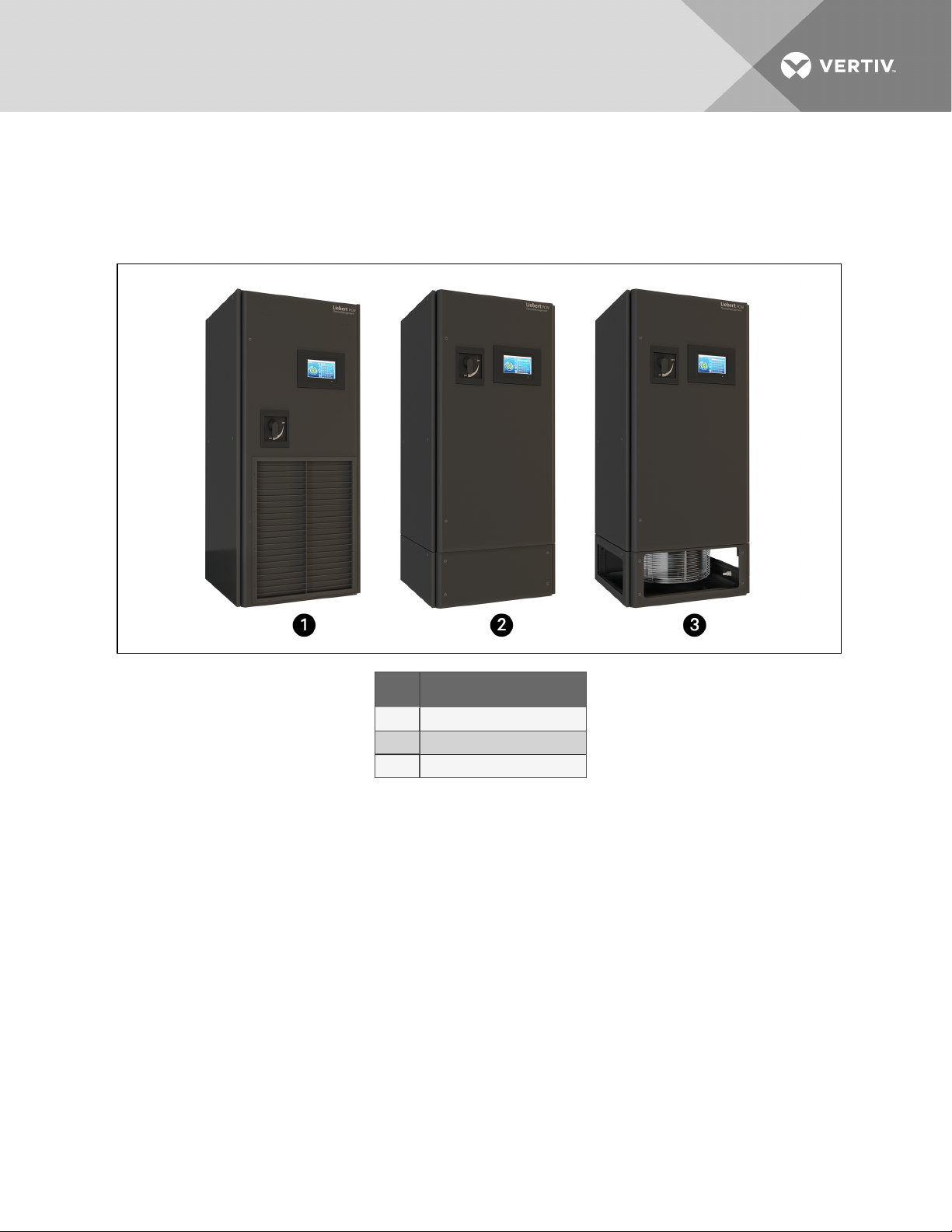
Figure 2.1 Liebert PDX/PCW Views
Item Description
1 Top-discharge, front-return unit
2 Raised-floor discharge unit
3 3-way floor-level discharge unit
Vertiv | Liebert® PDX™ and PCW™Installer/User Guide | 13
Page 14
2.1 Liebert PDX Model-number Nomenclature
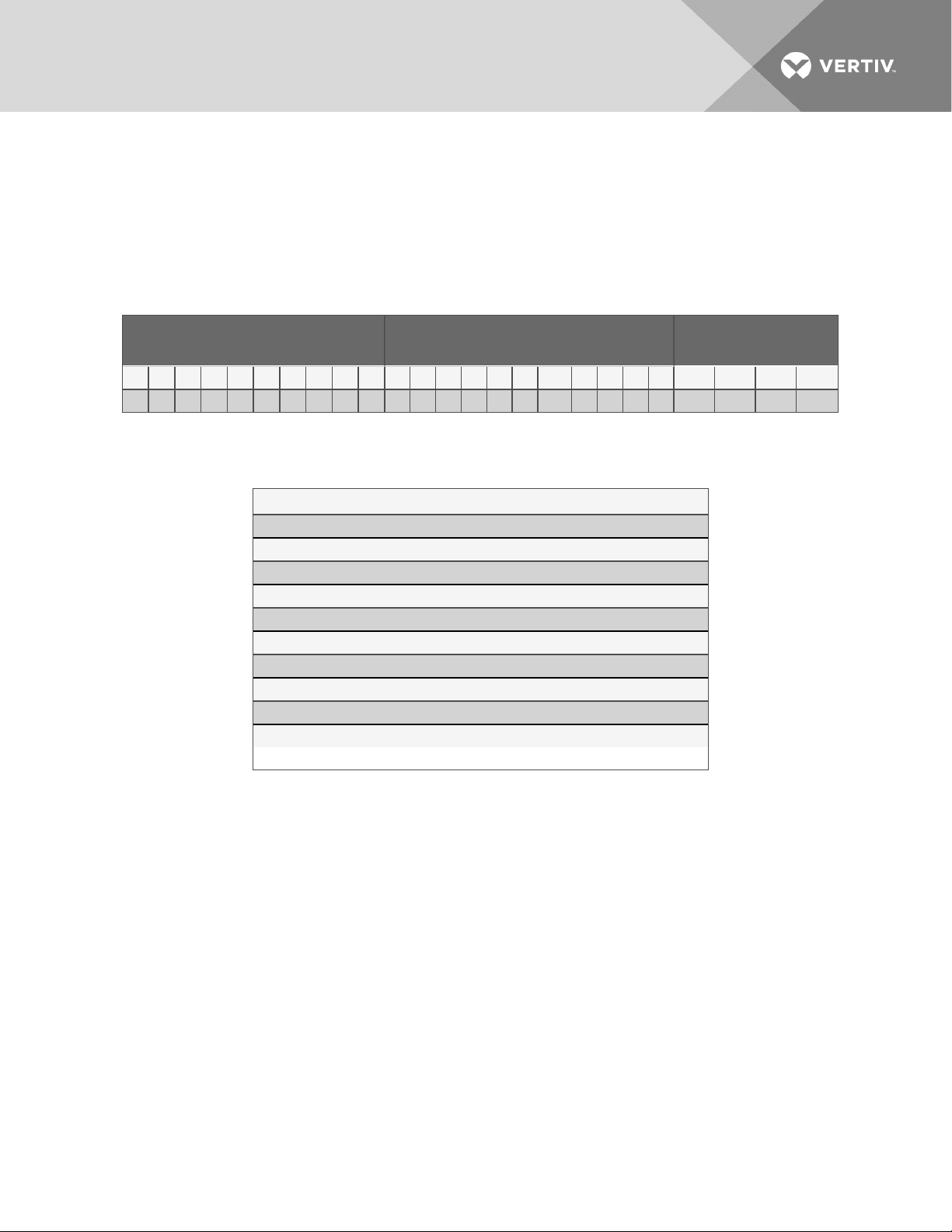
The tables below describe each digit of the 25-digitconfigurationnumber. The 14-digit model number
consists of the first 10 digits and last 4 digits of the configuration number.
For the full description of configuration and model number refer to Liebert PDX Model-number Detail on
page99.
Table 2.1 PDX 25-digit Configuration Number
Model Number Digi ts 1 to 10 Model Details
1 2 3 4 5 6 7 8 9 10 11 12 13 14 15 16 17 18 19 20 21 22 23 24 25
P X 0 2 9 D A 1 A D H H 2 8 0 1 P L U F P A # # #
ModelNumber Dig its
11 to14
Table 2.2 PDX Model-number Digit Summary
Digits 1 and2 = Unit Family
Digit3, 4, 5= Nominal Cooling Capacity, kW Digit16 = Enclosure Options
Digit6 = Air Direction and Discharge Digit17 = High-voltage Options
Digit7 = System Type Digit18 = Low- voltage Option Packages
Digit8 = Fan Type Digit19 = MonitoringCards
Digit9 = Power Supply Digit20 = Sensors
Digit10 = Compress or & Valve (R-410A) Digit21 = Packaging
Digit11 = Humidifier Digit22 = Factory Configuration code
Digit12 = Display Digit23-25 = Factory ConfigurationNumber
Digit13 = Reheat N/A
Digit14 = Air filter N/A
1. High-press ure MBV also results in high-pressure Econ-O-Coilvalve.
Digit15 Coil, Valve Type & Press ure Rating
1
Vertiv | Liebert® PDX™ and PCW™Installer/User Guide | 14
Page 15
2.2 Liebert PCW Model-number Nomenclature
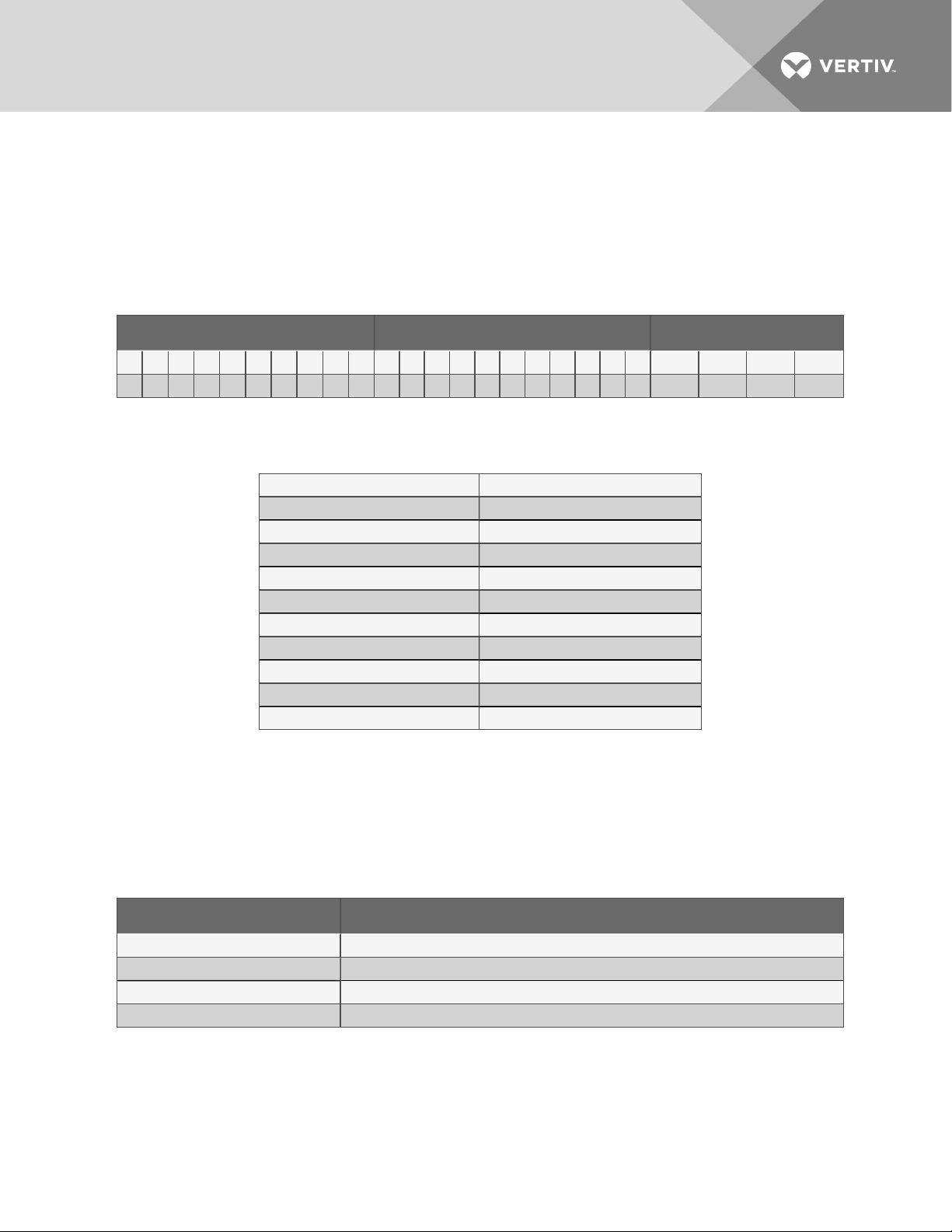
The tables below describe each digit of the 25-digitconfigurationnumber. The 14-digit model number
consists of the first 10 digits and last 4 digits of the configuration number.
For the full description of configuration and model number refer to Liebert PCW Model-number Detail on
page103.
Table 2.3 PCW 25-digit Configuration Number
Model Number Digi ts 1 to 10 Model Details ModelNumber Digits 11 to 14
1 2 3 4 5 6 7 8 9 10 11 12 13 14 1 5 16 17 1 8 19 20 21 22 23 24 25
P W 0 2 9 D C 1 A D H H 2 8 H 1 P L U F P A # # #
Table 2.4 PCW Model-number Digit Summary
Digits 1 and2 = Unit Family Digit15 = Coil
Digit3, 4, 5= Nominal Cooling Capacity, kW Digit 16 = Enclosure Options
Digit6 = Air Discharge Digit17 = High-voltage Options
Digit7 = System Type Digit18 = Low- voltage Option Packages
Digit8 = Fan Type Digit19 = MonitoringCards
Digit9 = Power Supply Digit 20 = S ensors
Digit10 = ChilledWater Valve andPressure Digit21 = Packaging
Digit11 = Humidifier Digit 22 = Factory Configuration code
Digit12 = Display Digit 23-25 = Factory Configuration Number
Digit13 = Reheat N/A
Digit14 = Air filter N/A
2.3 Component Location
The unit component locations are described in the submittal documents included in the Submittal
Drawings on page106.
The following table lists the relevant documents by number and title.
Table 2.5 Component-location Drawings
Document Number Titl e
DPN003004 PDX Component LocationD iagram, Downflow Models
DPN003005 PDX ComponentLocation Diagram, Upflow Models
DPN003020 PCW ComponentLocation Diagram, Downflow Models
DPN003021 PCW Component Location Diagram, Upflow Models
Vertiv | Liebert® PDX™ and PCW™Installer/User Guide | 15
Page 16

This page intentionally left blank.
Vertiv | Liebert® PDX™ and PCW™Installer/User Guide | 16
Page 17

3 PRE-INSTALLATION PREPARATIONANDGUIDELINES
NOTE: Before installing unit, determine whether any building alterations are required to run piping,
wiring and ductwork. Follow all unit dimensional drawings and refer to the submittal engineering
dimensional drawings of individual units for proper clearances.
Refer to Table B.2 on page100, or Table B.4 on page104, and submittal drawings to determine the type
of system being installed and anticipate building alterations, piping and ductwork needed.
The unit dimensions, pipe-connection locations, and piping schematics are described in the submittal
documents included in the Submittal Drawings on page106.
• Verify that the floor is level, solid and sufficient to support the unit. See Table 3.3 on page20
for unit weights.
• Confirm that the room is properly insulated and has a sealed vapor barrier.
• For proper humidity control, keep outside or fresh air to an absolute minimum (less than 5% of
total air circulated in the room).
• Do not install a Liebert PDX/PCW in an alcove or at the end of a long, narrow room.
• Install the units as close as possible to the largest heat load.
• Allow at least the minimum recommended clearances for maintenance and service. See the
appropriate submittal drawings for dimensions.
• We recommend installing an under-floor water detection system. Contact your Vertiv™
representative for information.
Vertiv | Liebert® PDX™ and PCW™Installer/User Guide | 17
Page 18
3.1 Planning Dimensions
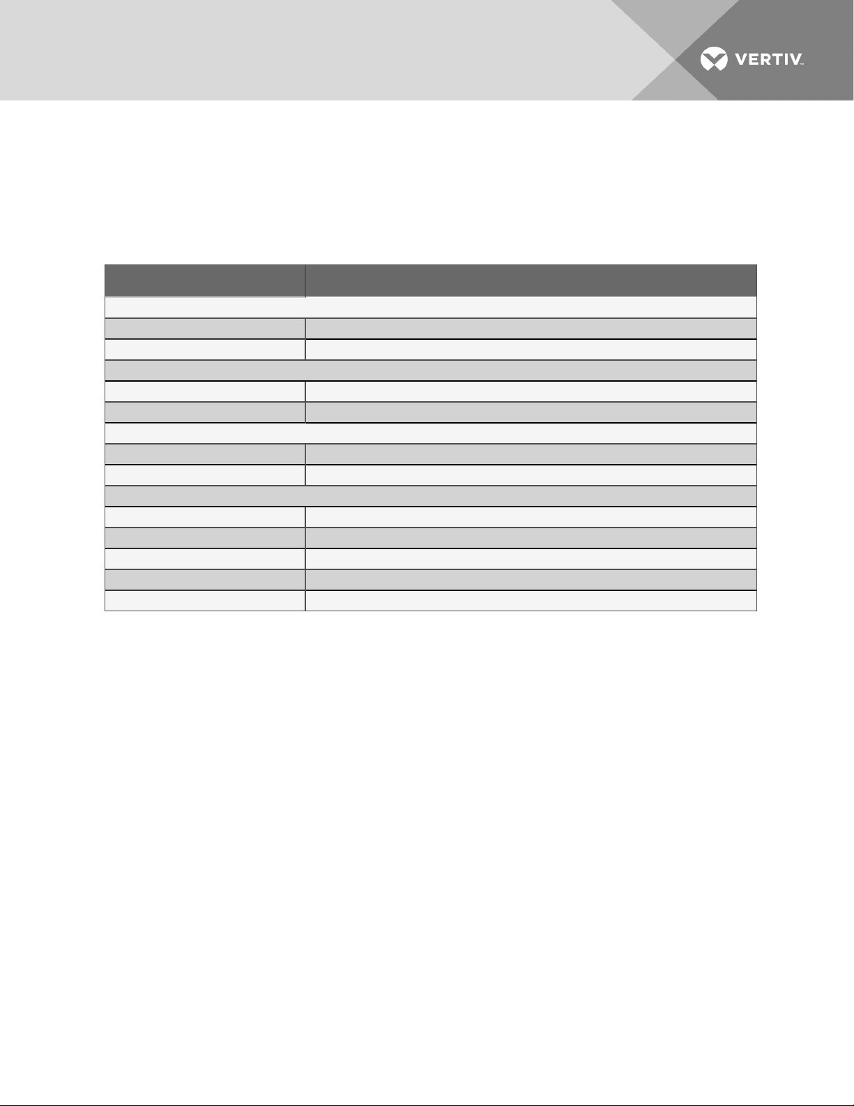
The unit, floor stand, and plenum dimensions are described in the submittal documents included in the
Submittal Drawings on page106.
The following table lists the relevant documents by number and title.
Table 3.1 Dimension Planning Drawings
Document Number Titl e
Downflow Units
DPN002936 Cabinet Dimensional Data, Downflow Models
DPN002944 CabinetDimensional Data, Downflow Floor L evel Discharge Models
Upflow Units
DPN002937 CabinetD imensional Data, Upflow Models
DPN002971 CabinetD imensional Data, Upflow Rear Return Models
Floor Stands
DPN002970 Floorstand & Floor PlanningDimensionalData, Downflow Models
DPN002971 Floorstand Dimensional D ata, Upflow Rear Return Models
Plenums
DPN002981 Plenum Dimensional Data, Upflow Discharge G rille
DPN003697 Plenum DimensionalData, Upflow Discharge w/ Duct Collar
DPN003447 Plenum Dimensional D ata, Top Discharge Upflow U nits
DPN003610 Downflow Plenum D imensional Data
DPN002936 Duct-flange Dimensions, Downflow models, Field-suppliedductwork
3.2 Considerations for Air Distribution
Depending on the intake/discharge configuration of the unit, consider the following when preparing for
installation:
When installing a downflow unit with raised-floor discharge:
• Verify that the raised floor is properly sized for the unit’s airflow and the room is free of airflow
restrictions.
• Perforated floor tiles in the raised floor should ensure minimal pressure loss.
• The raised floor must provide a minimum of 7-1/2in. (191mm) of clearance.
• Ensure that there is adequate clearance above the unit for return air. See DPN002936 in the
Submittal Drawings on page106.
When installing a downflow units with floor-level discharge:
• Provide several feet of clearance for air discharge of the unit.
• Ensure that there is adequate clearance above the unit for return air. See DPN002944 in the
Submittal Drawings on page106.
When installing upflow units
• Provide several feet of clearance for intake and discharge of the unit or for supply and return
ducting.
• Provide clearance for service access. See DPN002937 in the Submittal Drawings on page106.
Vertiv | Liebert® PDX™ and PCW™Installer/User Guide | 18
Page 19

3.3 Connections and System Setup
• The unit requires a drain, which must comply with all applicable codes. This drain line may
contain boiling water. See Field-installed, Gravity-fed Drain Line Requirements on page30, for
details.
• Three-phase electrical service is required for all models. Electrical service must conform to
national and local electrical codes. See equipment nameplate for details.
• Plan the routing of wiring, piping and ductwork to the unit. Refer to the appropriate piping
connection location drawings, piping schematics, and electrical-connection drawings for your
system in Submittal Drawings on page106.
• Water/glycol and GLYCOOL units utilizing a drycooler may require an optional aquastat
setting. See Table 9.7 on page89 and Table 9.8 on page89 for drycooler aquastat setting
guidelines. Applications with the optional stat setting require field piping to be insulated to
prevent condensation.
NOTE: Seal openings around piping and electrical connection to prevent air leakage. Failure to do so
could reduce the unit’s cooling performance.
3.4 Operating Conditions
The Liebert PDX/PCW must be operated in a conditioned space within the operating envelope that
ASHRAE recommends for data centers. Operating the PDX/PCW outside of this envelope can decrease
equipment reliability. Refer to ASHRAE’s publication, “Thermal Guidelines for Data Processing
Environments.”
3.4.1 Cooling, Humidification and Dehumidification
For operation in the Cooling, Humidification or Dehumidification modes, the Liebert PDX/PCW unit’s
return-air requirements for proper unit operation are:
• Maximum dew point of 59°F (15°C).
• Minimum 68°F (20°C)DB.
• Maximum 85° (29.4°C) DB for humidification mode and maximum 100˚F (37.7°C) DB for cooling
and dehumidification modes.
NOTE: Operating some PDX units equipped with ThermalExpansion Valves (TXVs) above80to85°F
(27to29.4°C) return air can cause the TXV to run out of stroke andresultin an increase in superheat
(above 20˚F) thuslimiting theunit’s capacity.
3.4.2 Heating
For operation in the Heating mode, the Liebert PDX/PCW unit’s return-air requirements for proper unit
operation are:
• Maximum dew point of 59°F (15°C).
• Maximum dry bulb of 80°F (27°C).
NOTE: Heating operation is not available when unit iCOM is set for Supply Air Control.
Vertiv | Liebert® PDX™ and PCW™Installer/User Guide | 19
Page 20
3.5 Shipping Dimensions andUnitWeights
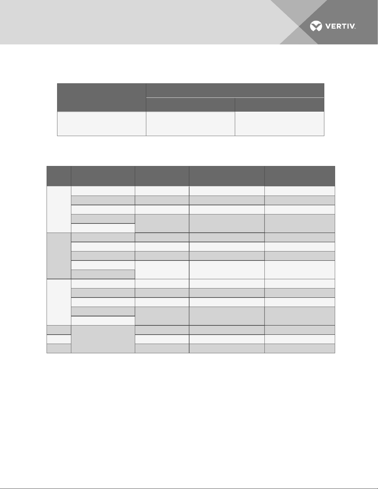
Table 3.2 Shipping dimensions for Liebert PDX/PCW
L x W x H, in. (mm)
Model Number
Domestic Export
PX011,PX018
PX023, PX029
PW011, PW017, PW029
45 x 4 5 x 85
(1143 x1143 x 21 59)
45 x 4 5 x 86
(1143 x1143 x 21 84)
Table 3.3 Unit Weights—approximate
Model
#
PX011
PX018
PX023
PX029
PW011
PW017 600 ( 272) 710 (322) 814 (369)
PW029 650 (294) 760 (345) 864 ( 392)
Cooling Type
Air 600 ( 272) 710 (322) 814 (369)
Air withEcon-O-Coil 700 (318) 810 (367) 914 (415)
Water/Glycol 620 ( 281) 730 (331) 831 (377)
Water/Glycol withEcon-O-Coil
GLYCOOL™
Air 670 (304) 780 (354) 884 (401)
Air withEcon-O-Coil 750 (340) 860 (390) 964 (437)
Water/Glycol 690 (313) 800 ( 363) 904 (410)
Water/Glycol withEcon-O-Coil
GLYCOOL
Air 700 (317) 810 (367) 914 (415)
Air withEcon-O-Coil 790 ( 358) 900 ( 408) 1004 (4 55)
Water/Glycol 720 (327) 830 (377) 934 (424)
Water/Glycol withEcon-O-Coil
GLYCOOL
ChilledWater
Dry Unit Weight lb.
(kg)
720 (327) 830 (376) 934 (424)
770 (349) 880 (399) 984 ( 446)
810 (367) 920 (4 17) 1024 (465)
575 (261) 685(311) 789(358)
Shipping Weight Domestic, lb.
(kg)
Shipping Weight Export, lb.
(kg)
NOTE: See capacity tables for unit liquid volume. Consult your factory sales rep for additional
component weight information.
Vertiv | Liebert® PDX™ and PCW™Installer/User Guide | 20
Page 21

4 EQUIPMENT INSPECTION AND HANDLING
SAFETY INFORMATION
WARNING! Risk of top-heavy unit falling over. Improper handling can cause equipment
damage, injury or death. Read all of the following instructions and verify that all lifting and
moving equipment is rated for the weight of the unit before attempting to move, lift, remove
packaging from or prepare the unit for installation. Unit weights are specified in Table 3.3 on
page20.
CAUTION: Risk of contact with sharp edges, splinters, and exposed fasteners. Can cause
injury. Only properly trained and qualified personnel wearing appropriate, OSHA-approved PPE
should attempt to move, lift, remove packaging from or prepare the unit for installation.
NOTICE
Risk of passageway interference. Can cause unit and/or structure damage. The unit may be
too large to fit through a passageway while on the skid. Measure the unit and passageway
dimensions, and refer to the installation plans prior to moving the unit to verify clearances.
NOTICE
Risk of damage from forklift. Can cause unit damage. Keep tines of the forklift level and at a
height suitable to fit below the skid and/or unit to prevent exterior and/or underside damage.
NOTICE
Risk of improper storage. Keep the unit upright, indoors and protected from dampness,
freezing temperatures and contact damage.
Upon arrival of the unit and before unpacking:
• Verify that the labeled equipment matches the bill of lading.
• Carefully inspect all items for visible or concealed damage.
• Report damage immediately to the carrier and file a damage claim with a copy sent to Vertiv™
or to your sales representative.
Equipment Recommended for Handling the Unit:
• Forklift
• Pallet jack
• Piano jacks
• Slings
• Spreader bars
4.1 Packaging Material
All material used to package this unit is recyclable. Please save for future use or dispose of the
material appropriately.
Vertiv | Liebert® PDX™ and PCW™Installer/User Guide | 21
Page 22
4.2 Handling the Unit while Packaged
If possible, ttransport the unit with a forklift or pallet jack. If that is not possible, use a crane with slings and
spreader bars that are rated for the weight of the unit..
When using a forklift or pallet jack:
• Ensure that the fork length is suitable for the unit length and, if adjustable, spread to the
widest allowable distance that will fit under the skid.
• When moving the packaged unit, and do not lift the unit any higher than 3in. (76 mm). All
personnel except those moving the unit must be kept 20ft(5m) or more from the unit while it
is being moved.
• If the unit must be lifted higher than 3in. (76 mm), all personnel not directly involved in moving
the unit must be 20ft (5m) or farther from the unit.
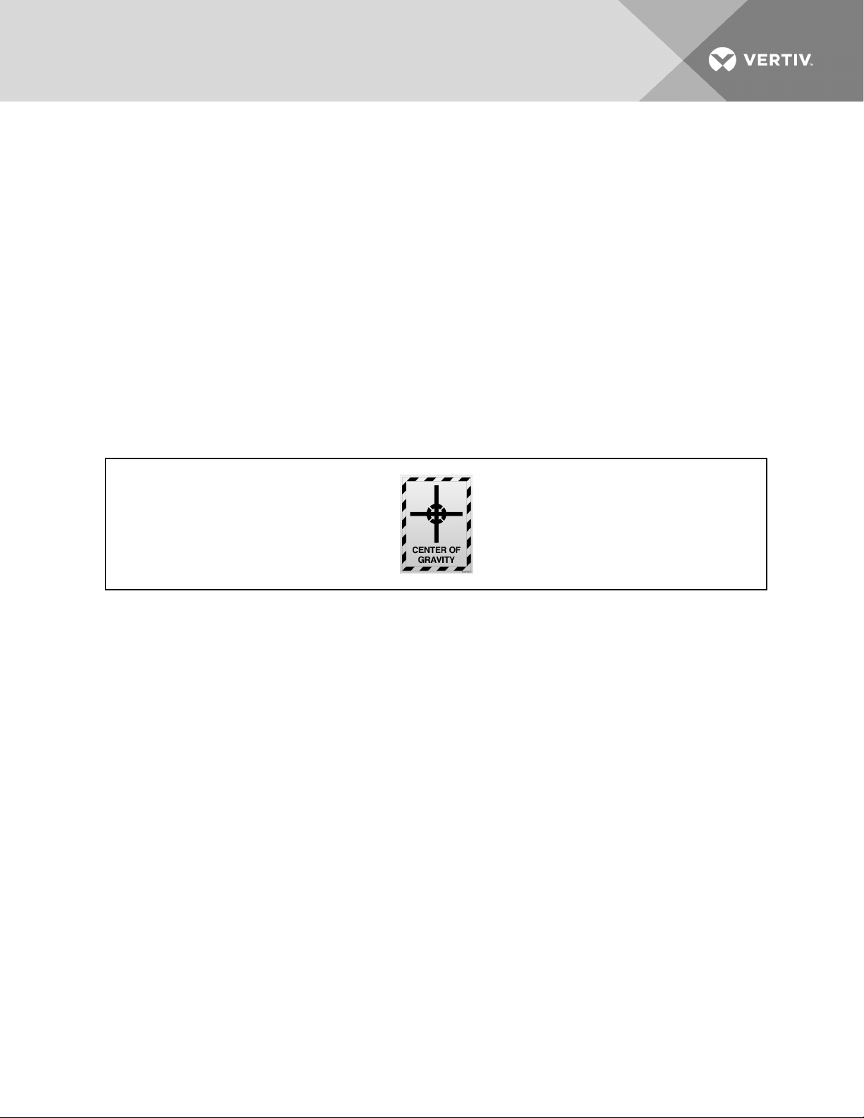
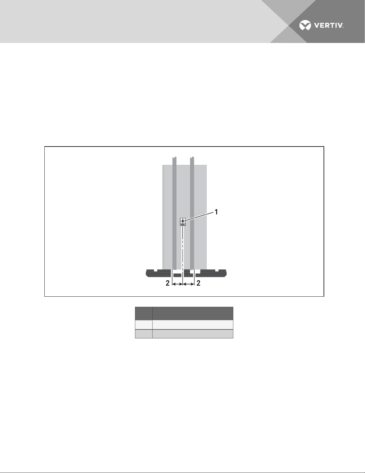
• Always refer to the location of the center-of-gravity indicators when lifting the unit from any
other side, see Figure 4.1 below.
Figure 4.1 Center-of-gravity indicator
4.3 Unpacking the Unit
1. Ship-loose items, if ordered, are secured to the unit package with stretch wrap. Remove the
stretch wrap and place the ship-loose box(es) to the side.
2. Remove the exterior stretch wrap packaging from around the unit and protective corner and
side packaging, as shown in Figure 4.2 on the facing page.
3. Remove the protective top and side package pads from the unit, exposing the bag over the
unit, see Figure 4.2 on the facing page.
NOTE: The bag may remain in place to protect from dust and to protect the unit panels, or it may be
removed for immediate installation.
Vertiv | Liebert® PDX™ and PCW™Installer/User Guide | 22
Page 23
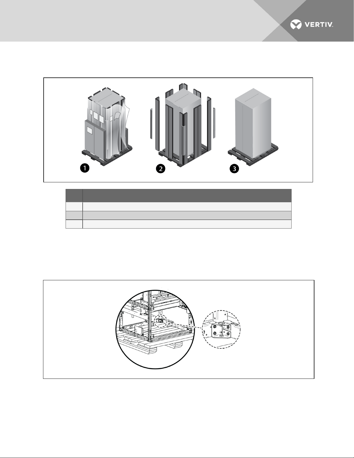
4. Remove the bag from the unit when ready to remove the skid and install the unit.
Figure 4.2 Unpacking the Unit
Item Description
1 Ship-loose items location, and r emoving exterior wrap fr om unit
2 Remove corner andside packagingplanks
3 Leave the bag on the unit until r eady to install.
4.3.1 Removing the Unit from the Skid with a Forklift
1. Remove the panels from the unit, and remove the 4 bolts attaching the unit to the skid. They
are inside unit base as shown in Figure 4.3 below.
Figure 4.3 Remove unit panels and bolts to skid
2. Align a forklift so the tines can be inserted under the unit.
3. Referring to Figure 4.4 on the next page:
• Insert the tines of the forklift completely under the base and beyond the opposite side of
the unit making sure they are level, not angled upward.
Vertiv | Liebert® PDX™ and PCW™Installer/User Guide | 23
Page 24
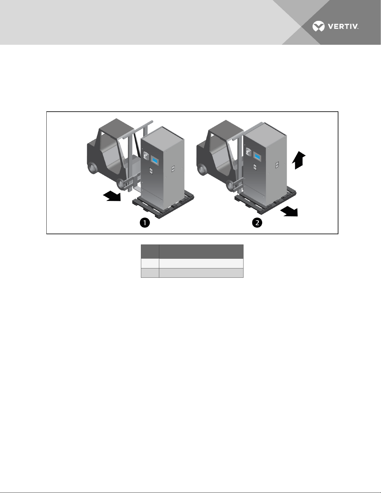
• Lift the unit off the skid to where the skid is not supporting the weight of the unit, and
remove the skid.
4. To move the unit with piano jacks, keep the unit elevated, and refer to Moving the Unit with
Piano Jacks on page27.
Figure 4.4 Remove the unit from the skid with a forklift
Item Description
1 Insert tines completely under base of unit.
2 Lift unit and remove skid.
Vertiv | Liebert® PDX™ and PCW™Installer/User Guide | 24
Page 25
4.3.2 Removing the Unit from the Skid Using Rigging
1. Remove the panels from the unit, and remove the 4 bolts attaching the unit to the skid. They
are inside unit base as shown in Figure 4.3 on page23.
2. Place slings under the unit using the spaces provided between the skid deck boards. Use the
center of gravity indicators on the unit to determine the position of the slings as shown in
Figure 4.5 below.
NOTE: The unit is shown without packaging. You may refer to these steps to move the unit with
rigging while the outer packaging is in place.
Figure 4.5 Center-of-gravity indicator and example sling placement
Item Description
1 Center-of-gravity mar ker
2 Equal distance between sling and marker.
Vertiv | Liebert® PDX™ and PCW™Installer/User Guide | 25
Page 26
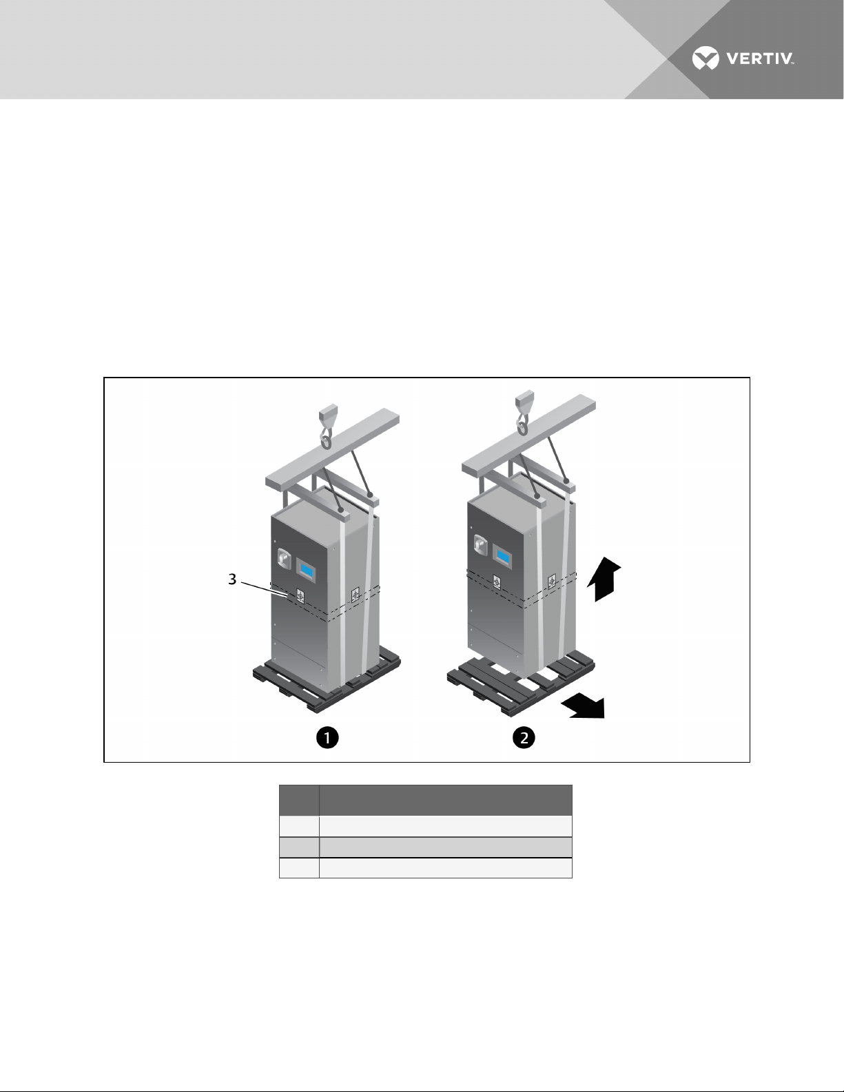
3. Referring to Figure 4.6 below:
• Use spreader bars or an equivalent device to protect the unit from crushing when it is
lifted with the slings. Ensure that the unit’s panels, if the bag is removed, are protected
from the slings.
NOTE: If rigging will be used to move the unit closer to the site for installation, place one or two
horizontal straps around the unit at mid-height.
• Lift the unit off the skid to a point where the weight of the unit is not resting on the skid,
and remove the skid from under the unit.
4. To move the unit with piano jacks, keep the unit elevated, and refer to Moving the Unit with
Piano Jacks on the facing page.
Figure 4.6 Remove the unit from the skid with rigging
Item Description
1 Use spreader bars and protect unitfrom slings.
2 Lift unit so that weight is noton skid, and remove the s kid.
3 Horizontal strap location, atmid-heightof unit.
Vertiv | Liebert® PDX™ and PCW™Installer/User Guide | 26
Page 27
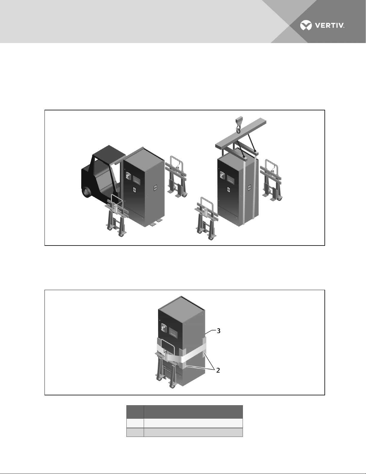
4.3.3 Moving the Unit with Piano Jacks
1. With the unit raised by a forklift, pallet jack or rigging according to the previous instructions,
position a piano jack on either side of the elevated unit, see Figure 4.7 below, then lower the
unit to a height suitable for the piano jacks.
Figure 4.7 Lower unit to piano jacks
2. Place protective padding between the unit and the piano jacks and straps, then secure the
unit to the piano jacks with the straps as shown in Figure 4.8 below.
Figure 4.8 Unit strapped to piano jacks
Item Description
2 Protective paddingbetween piano jacks andstraps.
3 Second piano jack onopposite side.
Vertiv | Liebert® PDX™ and PCW™Installer/User Guide | 27
Page 28

3. Depending on the method used, lower the forklift tines and move the forklift away or remove
the straps and move the rigging away.
4. Use the piano jacks to move the unit to the installation site.
• At least 2 properly-trained and qualified personnel are required to move the unit with
piano jacks.
5. Once the unit is in the installation location, remove the unit from the piano jacks:
• Lower the unit as far as the piano jacks will allow.
• Undo all straps holding the unit to the piano jacks.
• Use a pry bar or similar device to lift one end of the unit enough to remove one piano jack.
• Repeat the previous step to remove the piano jack on the opposite end.
• Remove the padding used to protect the unit from the piano jacks and strapping.
4.4 Placing the Unit on a Floor Stand
Liebert Floor Stand—Refer to the floor stand installation sheet shipped inside the floor stand package.
Lower the unit onto the floor stand.
NOTE: The floor stand for a Liebert PDX/PCW is not symmetrical. Its orientation to the unit is critical
for installation of the unit.
Vertiv | Liebert® PDX™ and PCW™Installer/User Guide | 28
Page 29
5 PIPING AND REFRIGERANT REQUIREMENTS
All fluid and refrigeration connections to the unit, with the exception of the condensate drain, are sweat
copper. Factory-installed piping brackets must not be removed. Field-installed piping must be installed in
accordance with local codes and must be properly assembled, supported, isolated and insulated. Avoid
piping runs through noise-sensitive areas, such as office walls and conference rooms.
Refer to specific text and detailed diagrams in this manual for other unit-specific piping requirements.
All piping below the elevated floor must be located so that it offers the least resistance to air flow. Careful
planning of the piping layout under the raised floor is required to prevent the air flow from being blocked.
When installing piping on the subfloor, we recommend that the pipes be mounted in a horizontal plane
rather than stacked one above the other. Whenever possible, the pipes should be run parallel to the air
flow.
The pipe connection locations, piping general arrangement and schematics are described in the
submittal documents included in the Submittal Drawings on page106.
The following tables list the relevant documents by number and title.
Table 5.1 Piping General-arrangment Drawings
Document Number Titl e
LiebertPDX PipingSchematics
DPN002929 Air Cooled Models with TXV
DPN003843 Air Cooled Models with EE V
DPN002931 Water/Glycol Models
DPN002932 GL YCOOL™ Models
DPN002972 Econ-O-Coil Models
LiebertPCWPipingSchematics
DPN002930 Chilled Water Models
DPN003737 HotWater Reheat
Table 5.2 Piping Connection Drawings
Document Number Titl e
Downflow Model Primary ConnectionLocations
DPN002938 Air Cooled, Raised Floor Models
DPN002945 Air Cooled, Front Discharge Models
DPN002942 Water/Glycol, Raised Floor Models
DPN002947 Water/Glycol, Front Discharge Models
DPN003520 GLYCOOL™ Raised Floor Models
DPN003522 G LYCOOL™ Front D ischarge Models
DPN002940 Chilled Water, Raised Floor Models
DPN002946 ChilledWater, Front Discharge Models
Upflow Model Primary Connection Locations
Vertiv | Liebert® PDX™ and PCW™Installer/User Guide | 29
Page 30

Table 5.2 Piping Connection Drawings (continued)
Document Number Titl e
DPN002939 Air Cooled Models
DPN002943 Water/Glycol Models
DPN003521 GLYCOOL™ Models
DPN002941 ChilledWater Models
5.1 Fluid Piping forAir-cooled,
Water/Glycol-cooledandChilled-waterPipingApplications
The following pipe connections are required:
• A drain line from the evaporator coil drain pan.
• A drain line from the secondary drain pan (if applicable).
• A water-supply line to the optional humidifier (if applicable).
• On air-cooled systems: refrigerant piping connections between the Liebert PDX and the
condenser. See Refrigerant Piping and Charging on page34.
• On chilled-water systems: connections to the building chilled-water source.
• On water-glycol systems: connections to a water or glycol loop.
5.1.1 Field-installed, Gravity-fed Drain Line Requirements
NOTICE
Risk of water backing up in the drain line. Leaking and overflowing water can cause equipment
and building damage.
Do not install an external trap in the drain line. This line already has a factory-installed trap
inside the cabinet. Installation of a second trap will prevent drain-water flow and will cause the
water to overflow the drain pan.
This line may contain boiling water. Use copper or other material that is rated for handling
boiling water for the drain line. Sagging condensate drain lines may inadvertently create an
external trap.
Vertiv | Liebert® PDX™ and PCW™Installer/User Guide | 30
Page 31

Observe the following requirements and refer to Figure 5.1 on the next page, when installing and routing
the drain line:
• The drain line must be sized for 2 gpm (7.6 l/m) flow.
• The drain line must be located so it will not be exposed to freezing temperatures.
• The drain should be the full size of the drain connection.
• The drain line must slope continuously away from the unit. Pitch drain line toward drain a
minimum of 1/8in. (3mm) per 1ft (305mm) of length.
• Drain is trapped internally. Do not externally-trap the drain line.
• The drain line must be rigid enough that it does not sag between supports, which
unintentionally creates traps.
• Use copper or other material suitable for draining water that can reach temperatures up to
212°F (100°C).
• The drain line must comply with all applicable codes.
• When the evaporator is installed below the level of the gravity-fed drain line, the optional
condensate pump kit is required. See the appropriate section, depending on the configuration
of your unit:
• Factory-installed CondensatePump in UpflowUnits on page33
• Field-installed Condensate Pump for Downflow Units on page33
Vertiv | Liebert® PDX™ and PCW™Installer/User Guide | 31
Page 32
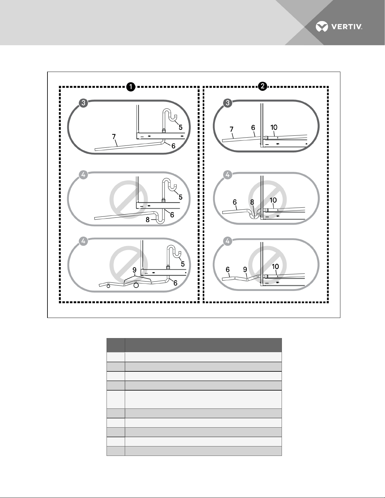
Figure 5.1 Correct and Incorrect gravity drains for downflow and upflow units
Table 5.3 Gravity-fed Drain Line Figure Descriptions
Item Description
1 For downflow units withdischarge into a raised floor
2 For upflow andfor downflow units withdischarge to the front or side
3 Correct drain installation
4 Incorrect drain installation
Internal drain and trap
5
NOTE: Units equipped with a condensate pump do not have an internal trap.
6 External drain
7 Continuous downward slope
8 External trap. Do not trap externally.
9 External traps, althoughunintentional. Lines must be rigid enoughnot to bow.
10 Internal drain and trap location. Drain and trap not shown in this view.
Vertiv | Liebert® PDX™ and PCW™Installer/User Guide | 32
Page 33

Factory-installed CondensatePump in UpflowUnits
NOTE: Condensate pumps are factory-installed on upflow units. They are shipped separately to be
field-installed on downflow units.
If your upflow unit requires a condensate pump, the pump is factory-installed inside the unit and a 1/2-in.
copper condensate-discharge connection is provided on the unit.
• 208-V condensate pump rated for 5 GPM at 45 ft (18.9l/m at 13.7m) of total head pressure.
• 230-V condensate pump rated for 5 GPM at 48 ft (18.9l/m at 14.6 m) of total head pressure.
• 460-V condensate pump rated for 5 GPM at 40 ft (18.9l/m at 12.2m) of total head pressure.
460-Vcondensate pump is also used on 380-V and 575-V units.
• Size discharge piping based on available condensate head.
Field-installed Condensate Pump for Downflow Units
NOTE: Condensate pumps are factory-installed on upflow units. They are shipped separately to be
field-installed on downflow units.
If your downflow unit requires a condensate pump, the pump is shipped separately to be field-installed
alongside the unit or beneath the raised floor. If installing beneath a raised floor, a minimum 11in (280mm)
floor height is required.
A 3/4-in. NPT-Female drain connection is provided on the unit.
• Drain is trapped internally. Do not trap external to unit.
• 208-V condensate pump rated for 5 GPM at 45 ft (18.9l/m at 13.7m) of total head pressure.
• 230-V condensate pump rated for 5 GPM at 48 ft (18.9l/m at 14.6 m) of total head pressure.
• 460-V condensate pump rated for 5 GPM at 40 ft (18.9l/m at 12.2m) of total head pressure.
460-Vcondensate pump is also used on 380-V and 575-V units.
• Size the discharge piping based on available condensate head.
5.1.2 Water Supply-line Requirements for the Optional Humidifier
The unit may have one of the following optional humidifiers. Refer to the appropriate supply-line piping
requirements if a humidifier is included on your unit:
Infrared Humidifier:
• 1/4-in. supply line, maximum water pressure is 150 psi (1034kPa).
• Size supply line for 1 gpm (3.8 l/m), with a minimum water pressure of 20psi(138kPa).
• Do not supply de-ionized water to the humidifier.
Vertiv | Liebert® PDX™ and PCW™Installer/User Guide | 33
Page 34

5.2 Refrigerant Piping and Charging
WARNING! Risk of over-pressurization of the refrigeration system. Can cause explosive
discharge of high-pressure refrigerant, loss of refrigerant, environmental pollution, equipment
damage, injury, or death. This unit contains fluids and gases under high pressure. Use extreme
caution when charging the refrigerant system. Do not pressurize the system higher than the
design pressure marked on the unit's nameplate. Local building or plumbing codes may require
installing a fusible plug or other type of pressure-relief device in the system.
CAUTION: Risk of excessive refrigerant line pressure. Can cause tubing and component
rupture resulting in equipment damage and personal injury. Do not close off the refrigerant-line
isolation valve for repairs unless a pressure-relief valve is field- installed in the line between the
isolation valve and the check valve. The pressure-relief valve must be rated 5% to 10% higher
than the system-design pressure. An increase in ambient temperature can cause the pressure
of the isolated refrigerant to rise and exceed the system-design pressure rating (marked on the
unit nameplate).
When field-installed isolation valves are used, consult DPN002929 and DPN003843, included in
Submittal Drawings on page106. Do not isolate any circuits from over-pressurization
protection.
Consult local building and plumbing codes for installation requirements of additional pressure-relief
devices when isolation valves are field installed. Do not isolate any refrigerant circuits from overpressurization protection.
NOTE: The Liebert indoor cooling unit has a factory-installed high-pressure safety switch in the highside refrigerant circuit. Consult local building codes to determine whether the Liebert MC Condensers
without receivers will require field-provided pressure-relief devices such as a fusible plug. A pressurerelief valve is provided with Liebert Lee-Temp™ receivers and an integral, fusible plug is provided on
PDX-EEV unheated receivers.
NOTICE
Risk of oil contamination with water. Can cause equipment damage.
LiebertPDX systems require the use of POE (polyolester) oil. POE oil absorbs water at a much
faster rate when exposed to air than previously used oils. Because water is the enemy of a
reliable refrigeration system, extreme care must be used when opening systems during
installation or service. If water is absorbed into the POE oil, it will not be easily removed and will
not be removed through the normal evacuation process. If the oil is too wet, it may require an oil
change. POE oils also have a property that makes them act as a solvent in a refrigeration
system. Maintaining system cleanliness is extremely important because the oil will tend to
bring any foreign matter back to the compressor.
Vertiv | Liebert® PDX™ and PCW™Installer/User Guide | 34
Page 35

NOTICE
Risk of improper refrigerant charging. Can cause equipment damage.
Refrigerant charge must be weighed into air-cooled compressorized systems before they are
started. Starting scroll and digital scroll compressors without proper refrigerant charging can
cause the compressors to operate at less than 5°F (–15°C) evaporator temperature and at less
than 20psig (138kPa). Operation for extended periods at less than 20psig (138kPa) can
cause premature compressor failure.
5.2.1 Refrigerant Piping Guidelines forAir-cooledSystems
• Air-cooled units ship with a nitrogen holding charge. Do not vent the evaporator until all
refrigerant piping is in place, ready for connection to the unit and condenser
• Use copper piping with a brazing alloy with a minimum temperature of 1350°F (732°C), such as
Sil-Fos. Avoid soft solders, such as 50/50 or 95/5.
• Use a flow of dry nitrogen through the piping during brazing to prevent formation of copper
oxide scale inside the piping. When copper is heated in the presence of air, copper oxide forms.
POE oils will dissolve these oxides from inside the copper pipes and deposit them throughout
the system, clogging filter driers and affecting other system components.
• A pure dry nitrogen flow of 1-3 ft3/min (0.5-1.5 l/s) inside the pipe during brazing is sufficient to
displace the air. Control the flow using a suitable measuring device.
• Ensure that the tubing surfaces to be brazed are clean and that all burrs have been removed
from the ends of the tubes.
• Ensure that all loose material has been cleaned from inside the tubing before brazing.
• Protect all refrigerant line components within 18in. (460mm) of the brazing site by wrapping
them with a wet cloth or with a suitable heat-sink compound.
• Isolate piping from building using vibration-isolating supports.
• Refer to Refrigerant Line Sizes and Equivalent Lengths on the next page for recommended
refrigerant piping sizes based on equivalent pipe lengths.
• Refer to Refrigerant Charge Requirements for Air-cooled Systems on the next page, for
refrigerant-charge amounts.
• Refer to condenser user manual for charging information.
• Condensers with receivers cannot be installed below the evaporator. The maximum height of
the condenser above the evaporator is 60ft (18.3m).
Consult the factory before installing units, condensers, and receivers outside these parameters.
• Install traps on hot-gas (discharge) lines at the base of vertical risers over 5ft(1.5m) and every
20ft(6m) for vertical rises over 25 ft (7.6m), then install a trap in 20-ft (6-m) increments or
evenly-divided over the vertical rise.
• Pitch horizontal hot-gas piping down at a minimum rate of 1/2in.per 10ft (42mm per 10m) so
that gravity will aid in moving oil in the direction of refrigerant/oil flow.
• Units with an Electronic Expansion Valve (EEV) must have EEV mounted below the receiver
liquid outlet.
• Consult factory if piping run exceeds 300ft (91m) equivalent length.
• Keep piping clean and dry, especially on units with R-410A refrigerant.
• Avoid piping runs through noise-sensitive areas.
Vertiv | Liebert® PDX™ and PCW™Installer/User Guide | 35
Page 36
• Do not run piping directly in front of discharge air stream.
• Refrigerant oil – do not mix oil types (see Compressor Oil on page85).
Refer to ASHRAE Refrigeration Handbook for general, good-practice refrigeration piping. The indoor
cooling unit has a factory-installed high-pressure safety switch in the high side refrigerant circuit. Consult
building codes to determine whether condensers without receivers require field-provided pressure relief
devices. A fusible plug kit is available for field installation on condensers without receivers.
NOTE: All indoor and outdoor field refrigerant piping must have at least 1/2 in. of insulation. All outdoor
insulation must be UV and ozone resistant.
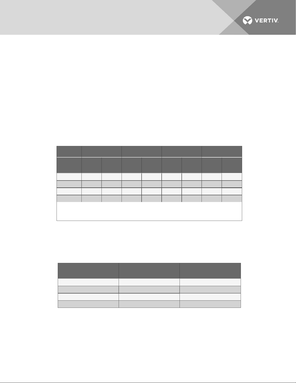
5.2.2 Refrigerant Line Sizes and Equivalent Lengths
Table 5.4 below lists requirements for field-installed refrigerant piping for the system.
Table 5.4 Recommended refrigerant line sizes for standard- and digital-scroll
models, OD Copper (inches)
Model PX011 PX018 PX023 PX029
Equivalent
Length
50 ft. (15 m) 1/2 3/8 5/8 1/2 3/4 5/8 7/8 5/8
100 ft. (30 m) 5/82 1/2 5/8 1 /2 3/4 5/8 7/8 5/8
150 ft. (45 m) 5/8
300 ft. (91 m) 5/8
1. Contact your Vertiv™ representative for line s izing for runs longer thanmaximum equivalent length shown in the table.
2. Must down-size vertical riser one trade size (1-1/8” to 7/8”, 7/8” to 3/4”, 3/4” to 5/8”, or 5/8” to 1/2”).
Source: DPN000788, Rev. 5
Hot Gas
Line
2
2
Liquid
Line
1/2 5/8 1/2 3/4 5/8 7/8 5/8
1/2 3/4
Hot Gas
Line
2
Liquid
Line
5/8 7/8
Hot Gas
Line
2
Liquid
Line
5/8 1- 1/8
Hot Gas
Line
2
Liquid
Line
3/4
5.2.3 Refrigerant Charge Requirements for Air-cooled Systems
The following tables provide the refrigerant charge requirements for the Liebert PDX, connected piping,
and condenser options.
Table 5.5 Approximate R-410A refrigerant charge forair-cooled Liebert PDX
Model
PX011 4.6 (2.1) 5.1 (2.3)
PX018 5.0 ( 2.3) 7.1 (3.2)
PX023 5.0 (2.3) 7.1 (3.2)
PX029 6.6 (3.0) 7.4 (3.4)
Downflow,
lb (kg)
Upflow,
lb (kg)
Vertiv | Liebert® PDX™ and PCW™Installer/User Guide | 36
Page 37
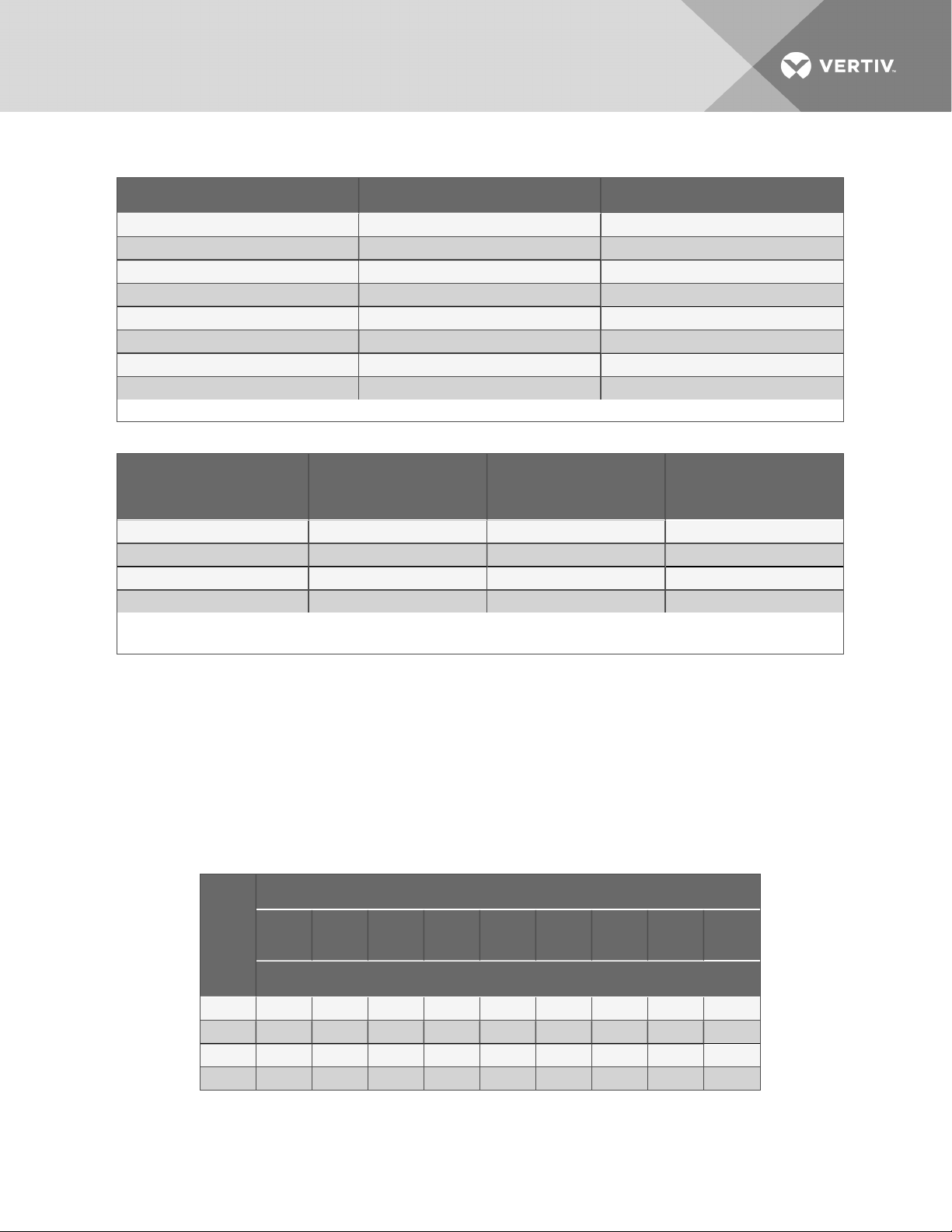
Table 5.6 Interconnecting piping refrigerant charge for R-410A, lbper 100ft(kgper30m)
Line Size, O.D., in. Liquid Line Hot Gas Line
3/8 3.2 (1.4) —
1/2 5.9 (2.7) 0.7 (0.3)
5/8 9.6 ( 4.3) 1.1 (0.5)
3/4 14.3 (6.4) 1.6 (0.7)
7/8 19.8 ( 8.8) 2.3 (1.0)
1-1/8 33.8 (15.1) 3.9 (1 .7)
1-3/8 51.5 ( 23.0) 5.9 (2.6)
1-5/8 — 8.4 (3.7)
Source: DPN003099, Rev. 0
Table 5.7 Condenser refrigerant charge approximateR-410A per circuit including receiver
CondenserModel
MCS028 2.5 (1.2) 21.7 (9.8) 11 .0 (5.0)
MCM040 3.5 (1.6) 22.7 (10.3) 1 2.0 (5.4)
MCL055 5.0 (2.3) 24.2 (11.0) 13.5 (6.1)
MCM080 8.5 (3.8) 39.8 (18.1) 17.0 (7.7)
1. Condenser charge includes receiver.
Source: DPN002411 Rev. 8
Condensers without
receivers, lb (kG)
Condensers
withLiebert Lee-Temp
receiver, lb (kG)
1
Condensers without Li ebert
Lee-Temp1receiver, lb (kG)
Additional Oil Requirements forScrollandDigital-scrollCompressors
See Table 5.8 below, for the amount required for various system charge levels.
After the system has been fully charged with refrigerant, use a hand pump to add the additional oil at the
suction side of the system while the system is running.
The amount of oil added by field service must be recorded on the tag marked “Oil Added Field Service
Record,” attached to each compressor. The date of oil addition must be included as well.
Table 5.8 Additional oil required per refrigerant charge
Refri gerant System Charge Per Circuit, lb (kg) *
Model
PX011 0 4 (120) 6 ( 180) 8 (240) 10 (300) 12 (360) 14 (410) 16 (480) 18 (530)
PX018 0 6 (180) 9 (270) 12 (360) 15 (440) 18 (530) 21 (620) 24 (720) 27 (800)
PX023 0 6 ( 180) 9 ( 270) 12 (360) 15 (440) 18 ( 530) 21 (620) 24 (720) 27 (800)
PX029 0 6 (180) 9 (270) 12 (360) 15 (440) 18 (530) 21 (620) 24 (720) 27 (800)
<40
(18.1)
40
(18.1)50(22.7)60(27.2)
Additional Oil Required Per Circuit, oz (ml)
70
(31.8)80(36.3)90(40.8)
100
(45.4)
110
(49 .9)
Vertiv | Liebert® PDX™ and PCW™Installer/User Guide | 37
Page 38
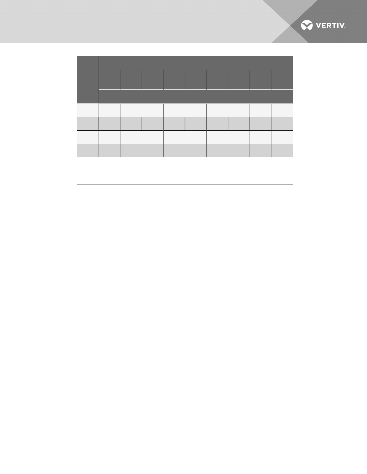
Refri gerant System Charge Per Circuit, lb (kg) *
NOTICE
Model
PX011
PX018 30 (890) 33 ( 980)
PX023 30 (890) 33 (980)
PX029 30 (890) 33 (980)
*Sys tem Charge = indoor unit + condenser + r efrigerant r eceiver + refrigerant lines.
For system charges over 200 lb. (90.7kg), consult your Vertiv™ r epresentative.
See Table 9.6 on page85for the r ecommended oil for the system.
Source:DPN003950 Rev. 1
120
(54.4)
20
(600)
130
(59.0)
22 (650) 24 (720) 26 (770) 28 ( 840) 30 (890) 32 (960)
140
(63.5)
Additional Oil Required Per Circuit, oz (ml)
36
(1080)39(1150)42(1260)45(1330)48(1440)51(1510)54(1620)
36
(1080)39(1150)42(1260)45(1330)48(1440)51(1510)54(1620)
36
(1080)39(1150)42(1260)45(1330)48(1440)51(1510)54(1620)
150
(68.0)
160
(72.6)
170
(77.1)
180
(81.6)
190
(86.3)
34
(1010)36(1080)
200
(90.7)
Risk of improper compressor lubrication. Can cause compressor and refrigerant system
damage.
Failure to use oil types, viscosities and quantities recommended by the compressor
manufacturer may reduce compressor life and void the compressor warranty.
• Do not mix polyolester (POE) and mineral-based oils.
• Do not mix oils of different viscosities.
• Consult your local sales representative, Vertiv™ product support at 1-800-543-2778, or
the compressor manufacturer if questions arise.
Vertiv | Liebert® PDX™ and PCW™Installer/User Guide | 38
Page 39

5.2.4 Evacuation, Leak-testing, and Charging Air-cooledSystems withTXV
andwithoutReceivers
A discharge line and liquid line must be field-installed between the indoor unit and the outdoor
condenser. See the appropriate piping schematic, listed in Table 5.1 on page29.
Evacuation and Leak-testing Air-cooled SystemswithoutReceivers
For proper leak-check and evacuation, you must open all system valves and account for all check valves.
NOTE: The system includes a factory-installed check valve and an additional downstream Schrader
valve with core in the compressor discharge line. Proper evacuation of the condenser side of the
compressor can be accomplished only using the downstream Schrader valve. See the appropriate
piping schematic for your system in the submittal-drawings appendix.
1. If unit power is available, open the unit liquid-line solenoid valves using the evacuation function
for System #1 in the diagnostic section of the Liebert iCOM™ controller.
– or –
If unit power is not available, connect a field-supplied 24-VAC/75-VA power source directly to
the unit solenoid valve.
2. Connect refrigerant gauges to the suction rotalock valves and discharge-line Schrader valves.
3. Open the service valves and place a 150 PSIG (1034kPa) of dry nitrogen with a tracer of
refrigerant. Check system for leaks with a suitable leak detector.
4. After completion of leak testing, release the test pressure, (observe local code) and pull an
initial deep vacuum of 500 microns on the system with a suitable pump.
5. After 4hours, check the pressure readings and, if they have not changed, break vacuum with
dry nitrogen. Pull a second and third vacuum to 500 microns or less. Re-check the pressure
after 2hours.
When the 3 checks are complete, proceed to ChargingAir-cooled Systems without Receivers
below.
ChargingAir-cooled Systems without Receivers
NOTICE
Risk of improper refrigerant charging. Can cause equipment damage.
R-410A is a blended refrigerant and must be introduced and charged from the cylinder only as
a liquid.
When adding liquid refrigerant to an operating system, it may be necessary to add the
refrigerant through the compressor suction service valve.service . Care must be exercised to
avoid damage to the compressor. We recommend connecting a sight glass between the
charging hose and the compressor suction service valve. This will permit adjustment of the
cylinder hand valve so that liquid can leave the cylinder while allowing vapor to enter the
compressor.
Vertiv | Liebert® PDX™ and PCW™Installer/User Guide | 39
Page 40

NOTICE
Risk of refrigerant overcharge. Can cause equipment damage.
Do not use the sight glass as an indicator when charging Liebert MC condenser systems.
The system must be fully piped and evacuated before it can be charged. See Evacuation and Leak-
testing Air-cooled SystemswithoutReceivers on the previous page.
Liebert MC condensers are charge-sensitive and require accurate calculation of the system charge to
avoid overcharging. To avoid overcharge, the following additional guidelines are recommended to ensure
trouble-free operation.
• When charging system in an outdoor ambient below 50°F (10°C), recheck the subcooling
against Table 5.9 on the facing page when the ambient is above 60°F (15.6°C)
• The indoor space should be maintained at 70 to 80°F (21 to 26.7°C) return air before final
charge adjustments are made.
• Charging unit at greater than 80°F (26.7°C) return air and low outdoor ambient temperature
may result in the unit being overcharged.
• Charge by subcooling measurement at the indoor unit. See Table 5.9 on the facing page for
target subcooling temperatures.
• Pressure and temperature measuring instruments should be capable of measuring to ±10psig
(68.9kPa) and ± 2°F (1.1°C) for best subcooling measurement.
To calculate the charge for the system:
1. Check the nameplate on the indoor unit for refrigerant type to be used. Unit control
configurations differ depending on refrigerant type.
2. The unit must be operating. Refer to the following if necessary:
• Checklist for Completed Installation on page57 to operate the system.
• The operating manual for the Liebert MC Condenser.
Manuals are available at https://www.vertivco.com/en-us/support/.
3. Calculate the amount of charge for the system. See Refrigerant Charge Requirements for
Air-cooled Systems on page36.
4. Accurately weigh in as much of the system charge as possible before starting the unit. Do not
exceed the calculated charge by more than 0.5 lb (.23kg).
5. Turn on the Liebert MC disconnect switch.
Vertiv | Liebert® PDX™ and PCW™Installer/User Guide | 40
Page 41
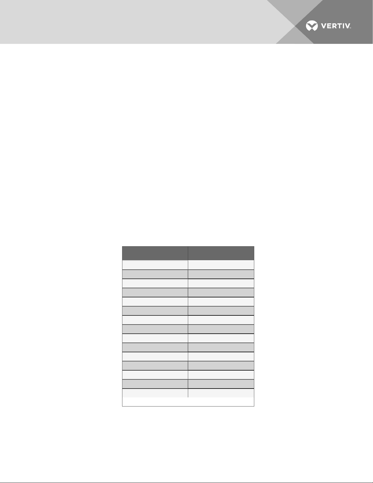
6. Turn on the Liebert PDX/PCW disconnect switch, and operate the unit for 30minutes using
the charging function for each circuit of the system.
• You must operate the indoor fan using the "Diagnostic" menu of the Liebert iCOM control.
• A minimum 20psig (138kPa) must be established and maintained for the compressor to
operate.
• The charging function operates the compressor at full capacity and energizes the liquidline solenoid valve. The reheat and humidifier are disabled.
• The charging function can be reset as many times as required to complete unit charging.
7. Attach pressure and temperature instruments to the liquid-line of the indoor unit, measure the
initial subcooling, and continue to add charge until the recommended subcooling for the
current outdoor ambient temperature is reached. See Table 5.9 below. Read the outdoor
ambient temperature from the Liebert MC condenser control menu ID F02.
NOTE: To determine subcooling measurement, you must measure the liquid-line pressure reading (at
the factory-installed Schrader tap) and obtain a temperature reading on the liquid line. Convert the
liquid-line pressure reading into a liquid temperature using a Pressure-Temperature Guide or Table 5.10
on the next page. Subtract the measured temperature from the saturated-liquid temperature. The
difference is subcooling. Make sure to use the saturated liquid temperature to calculate subcooling.
8. As head pressure builds, the variable-fan-speed controlled condenser fan begins rotating. The
fan will run at full speed when sufficient head pressure is developed.
Table 5.9 Target subcooling
forambientoutdoor temperature
Ambient Temp, °F(°C) Subcooling, °F(°C)
0 (-17.8) 22 (12.0)
10 (-1 2.2) 22 (12.0)
20 (-6.7) 22 (12.0)
30 (-1.1) 22 (12.0)
40 (4.4) 22 (12.0)
50 (10.0) 21 (11 .7)
60 ( 15.6) 19 ( 10.8)
70 (21.1) 17 (9.3)
80 ( 26.7) 13 (7.2)
90 ( 32.2) 9 (5.0)
95 (35.0) 7 (3.9)
100 (37.8) 5 ( 2.9)
105 (40.6) 3 ( 1.8)
110 (4 3.3) 1 (0.7)
125 (51.7) 0
DPN002411 , Rev. 8
Vertiv | Liebert® PDX™ and PCW™Installer/User Guide | 41
Page 42
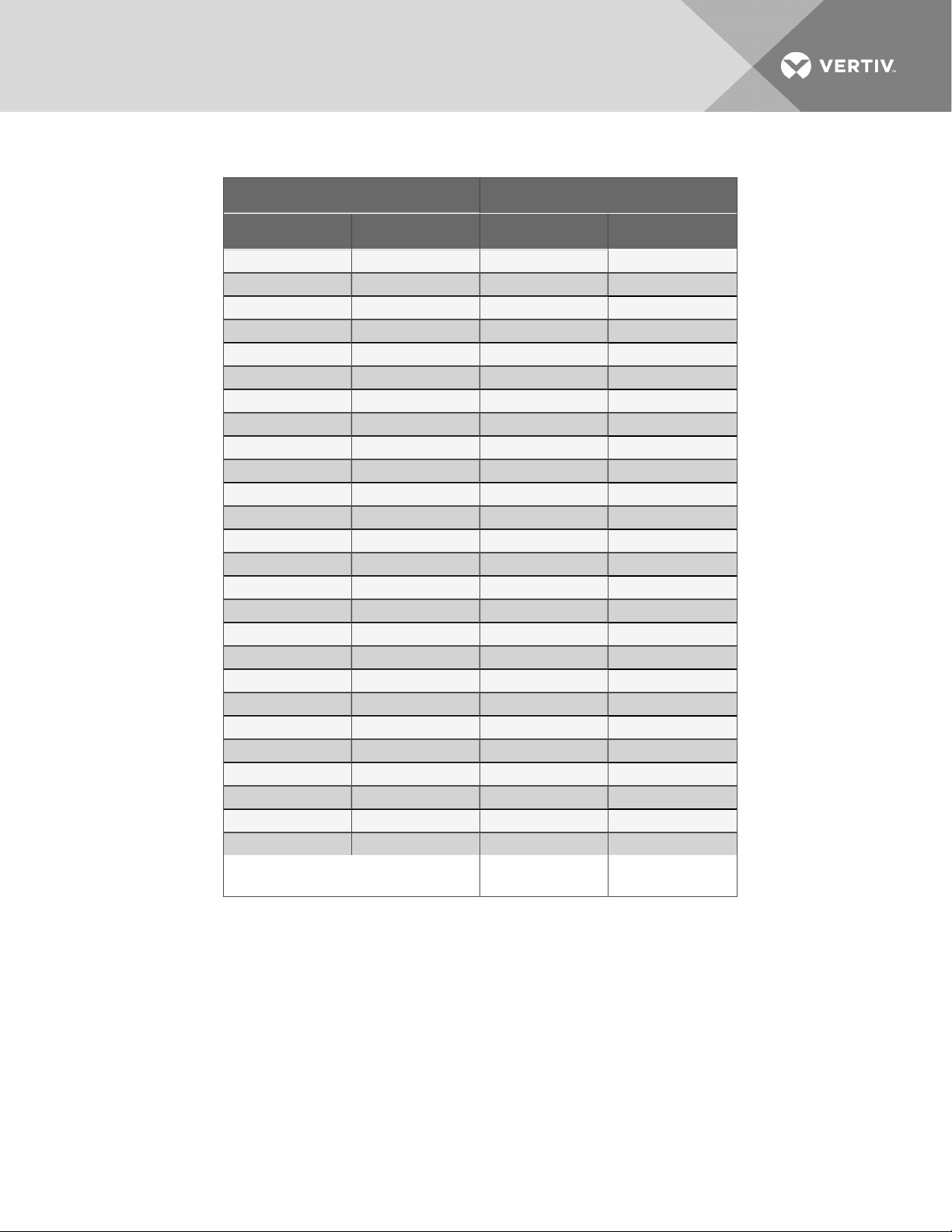
Table 5.10 Liquid pressure andtemperature chart—R-410A
Pressure Temperature*
PSIG BarG °F °C
170 11 .7 59.8 15.4
180 12.4 63.1 17.3
190 13.1 66.3 19.1
200 13.8 69.5 20.8
210 1 4.5 72.5 22.5
220 15.2 75.4 24.1
230 15.9 78.2 25.7
240 16.6 80.9 27.2
250 17.2 83.6 28.7
260 17.9 86.2 30.1
270 18.6 88.7 31.5
280 19.3 91.1 32.8
290 20.0 93.5 34 .2
300 20.7 95.8 35.5
310 21 .4 98.1 36.7
320 22.1 100.3 38.0
330 22.8 102.5 39.2
340 23.4 104.6 40.3
350 24 .1 1 06.7 4 1.5
360 24 .8 108.7 42.6
370 25.5 110.7 43.7
380 26.2 112.7 44 .8
390 26.9 114.5 45.9
400 27.6 116.4 46.9
500 34 .5 133.5 56.4
600 41.4 148.1 64.5
* Values are for saturated liquid
Source: DPN002411 , Rev. 8
Vertiv | Liebert® PDX™ and PCW™Installer/User Guide | 42
Page 43

5.2.5 Evacuation, Leak-testing, and Charging Air-cooled Systems withLiebertLeeTemp™ “Flooded-condenser” Head-pressureControlSystem
The Liebert Lee-Temp system consists of a modulating-type head-pressure control valve and insulated
receiver with heater pad to ensure operation at ambient temperatures as low as -30°F (-34.4°C). The
Liebert Lee-Temp system can be used with any PDX compressor or expansion-valve choice.
A discharge line and liquid line must be field-installed between the indoor unit and the outdoor
condenser. See the appropriate piping schematic, listed in Table 5.1 on page29.
Liebert Lee-Temp-controlled Materials Supplied
• Built-in, pre-wired condenser control box
• Air-cooled condenser
• Piping access cover
• Bolts—4per leg (3/8in. x 5/8in.)
• Terminal block for 2-wire, 24-V interlock connection between unit and condenser
• Terminal blocks for shielded, CANbus-cable connection between unit and condenser
• Condenser legs—4with 1-fan units and 5with 2-fan units
• Bolts—6per receiver (3/8in. x 1in.)
• Liebert Lee-Temp system:
• Insulated storage receiver with (2) liquid-level sight glasses—1
• Head-pressure control-valve piping assembly with (2) integral check valves—1
• Service valve—1
• Pressure-relief valve—1Pressure-relief valve—1
NOTE: The Lee-Temp heater pad requires a separate, continuous electrical source. See nameplate on
unit for proper voltage.
Evacuation and Leak-testing Air-cooled Systems withLiebertLee-Temp Receiver
For proper leak-check and evacuation, you must open all system valves and account for all check valves.
NOTE: The system includes a factory-installed check valve and an additional downstream Schrader
valve with core in the compressor discharge line. Proper evacuation of the condenser side of the
compressor can be accomplished only using the downstream Schrader valve. See the appropriate
piping schematic for your system in Submittal Drawings on page106.
1. If unit power is available, open the unit liquid-line solenoid valve or electronic-expansion valve
(EEV) using the evacuation function in the diagnostic section of the Liebert iCOM® control.
– or –
If unit power is not available, connect a field-supplied 24-VAC/75-VA power source directly to
the unit solenoid valve.
NOTE: Unit power is required for PDX with EEV.
2. Connect a jumper hose from the service-valve fitting on the outlet of the receiver and the
Schrader fitting on the discharge header of the condenser. Seat the service valve
approximately two(2) turns from the fully back-seated position.
Vertiv | Liebert® PDX™ and PCW™Installer/User Guide | 43
Page 44

3. At the compressor, connect refrigerant gauges to the suction rotalock valves and dischargeline Schrader valves.
4. Open the service valves and place a 150 PSIG (1034kPa) charge of dry nitrogen with a tracer of
refrigerant. Check system for leaks with a suitable leak detector.
5. After completion of leak testing, release the test pressure, (observe local code) and pull an
initial deep vacuum of 500microns on the system with a suitable pump.
6. After 4hours, check the pressure readings and, if they have not changed, break vacuum with
dry nitrogen. Pull a second and third vacuum to 500 microns or less. Re-check the pressure
after 2hours.
When the 3 checks are complete, remove the jumper hose from the service-valve fitting and
the condenser, and proceed to Charging Air-cooled Systems withLiebertLee-Temp Receiver
below.
Charging Air-cooled Systems withLiebertLee-Temp Receiver
NOTICE
Risk of improper refrigerant charging. Can cause equipment damage.
R-410A is a blended refrigerant and must be introduced and charged from the cylinder only as
a liquid.
When adding liquid refrigerant to an operating system, it may be necessary to add the
refrigerant through the compressor suction service valve.service . Care must be exercised to
avoid damage to the compressor. We recommend connecting a sight glass between the
charging hose and the compressor suction service valve. This will permit adjustment of the
cylinder hand valve so that liquid can leave the cylinder while allowing vapor to enter the
compressor.
NOTICE
Risk of improper operation. Can cause compressor failure.
Operating the unit with the EEV closed can cause compressor failure. The reheat and
humidifier are disabled. A minimum of 20 psig (138 kPa) must be established and maintained
for the compressor to operate. The charging function can be reset as many times as required
to complete
To calculate the charge for the system:
1. Check the nameplate on the indoor unit for refrigerant type to be used. Unit control
configurations differ depending on refrigerant type.
2. The unit must be operating, refer to .
3. Calculate the amount of charge for the system. See Refrigerant Charge Requirements for
Air-cooled Systems on page36.
4. Accurately weigh in as much of the system charge as possible before starting the unit.
Vertiv | Liebert® PDX™ and PCW™Installer/User Guide | 44
Page 45

5. Turn on unit disconnect switch, and operate the unit for 30 minutes using the charging
function in the "Diagnostic" menu of the Liebert iCOM controller.
• A minimum 20psig (138kPa) must be established and maintained for the compressor to
operate.
• The charging function operates the compressor at full capacity and energizes the liquidline solenoid valve. The reheat and humidifier are disabled.
• The charging function can be reset as many times as required to complete unit charging.
6. Charge the unit until the liquid-line sight glass becomes clear. Then add an additional 1lb
(0.45kg) of refrigerant.
NOTE: A digital scroll compressor will have a clear sight glass only when operating at 100% capacity.
When operating below 100%, the sight glass may show bubbles with each 15-second unloading cycle.
Refrigerant-level Sight Glasses ontheLiebertLee-Temp Receiver
On the receiver(s) at the condenser are 2refrigerant-level sight glasses. Refrigerant level will vary with
outside temperature. Check refrigerant level after the unit has been on for at least 15 minutes.
Sight Glass Levels at Outdoor Temperatures
• 40°F (4.5°C) and lower—bottom sight glass is 3/4 full
• 40 to 60°F (4.5 to 15.5°C)—bottom sight glass is full
• 60°F (15.5°C) and higher—top sight glass is 3/4 full
5.2.6 Evacuation, Leak-testing andChargingAir-cooled Systems
withEEVandUnheatedReceivers
The PDX with EEV uses an unheated receiver to balance refrigerant requirements of the evaporator coil
and MCcondenser coil(s). See DPN00293
A discharge line and liquid line must be field-installed between the indoor unit and the outdoor
condenser. See the appropriate piping schematic, listed in Table 5.1 on page29.
Evacuation and Leak-testing Air-cooled Systems withUnheated Receivers
For proper leak-check and evacuation, you must open all system valves and account for all check valves.
NOTE: The system includes a factory-installed check valve and an additional downstream Schrader
valve with core in the compressor discharge line. Proper evacuation of the condenser side of the
compressor can be accomplished only using the downstream Schrader valve. See the appropriate
piping schematic for your system in the submittal-drawings appendix.
1. Open the electronic-expansion valves for evacuation.
2. Connect refrigerant gauges to the suction rotalock valve and discharge line Schrader valve.
3. Open the service valves and place a 150 PSIG (1034 kPa) of dry nitrogen with a tracer of
refrigerant. Check system for leaks with a suitable leak detector.
Vertiv | Liebert® PDX™ and PCW™Installer/User Guide | 45
Page 46

4. After completion of leak testing, release the test pressure, (observe local code) and pull an
initial deep vacuum of 500 microns on the system with a suitable pump.
5. After 4hours, check the pressure readings and, if they have not changed, break vacuum with
dry nitrogen. Pull a second and third vacuum to 500 microns or less. Re-check the pressure
after 2hours.
When the 3 checks are complete, proceed to Charging Air-cooled Systems with
UnheatedReceivers below.
Charging Air-cooled Systems with UnheatedReceivers
NOTICE
Risk of improper refrigerant charging. Can cause equipment damage.
R-410A is a blended refrigerant and must be introduced and charged from the cylinder only as
a liquid.
When adding liquid refrigerant to an operating system, it may be necessary to add the
refrigerant through the compressor suction service valve.service . Care must be exercised to
avoid damage to the compressor. We recommend connecting a sight glass between the
charging hose and the compressor suction service valve. This will permit adjustment of the
cylinder hand valve so that liquid can leave the cylinder while allowing vapor to enter the
compressor.
NOTICE
Risk of refrigerant overcharge. Can cause equipment damage.
Do not use the sight glass as an indicator when charging Liebert MC condenser systems.
To calculate the charge for the system:
1. Check the unit's nameplate for refrigerant type to be used. Unit control configurations differ
depending on refrigerant type.
2. The unit must be operating, refer to Checklist for Completed Installation on page57.
3. Calculate the amount of charge for the system. See Refrigerant Charge Requirements for
Air-cooled Systems on page36.
4. Accurately weigh in as much of the system charge as possible before starting the unit. Do not
exceed the calculated charge by more than 0.5 lb (.23kg).
5. Turn on the Liebert MC Condenser disconnect switch.
NOTE: We recommend charging the unit with the return-air setpoint between 75°F to 85°F (24 to
29°C). The return-air temperature to the charged unit must be stable and must be maintained greater
than 65°F (18°C). If this is not possible from lack of heat load, then use load banks to offset the cooling
load during start up. See Refrigerant-level Sight Glasses ontheUnheated Receiver on the facing page
for the proper charge level in the receiver based on return-air temperature and outdoor temperature at
time of charging.
6. Turn on the indoor-unit disconnect switch.
Vertiv | Liebert® PDX™ and PCW™Installer/User Guide | 46
Page 47

7. Turn on the Liebert PDX/PCW disconnect switch, and operate the unit for 30minutes using
the charging function for each circuit of the system.
• You must operate the indoor fan using the "Diagnostic" menu of the LiebertiCOM control.
• A minimum 20psig (138kPa) must be established and maintained for the compressor to
operate.
• The charging function operates the compressor at full capacity and closes the EEV. The
reheat and humidifier are disabled.
• The charging function can be reset as many times as required to complete unit charging.
NOTICE
Risk of improper operation. Can cause compressor failure. Operating the unit with the EEV
closed can cause compressor failure.
NOTE: A digital-scroll compressor can have a clear sight glass only when operating at 100% capacity.
When operating with a receiver, the sight glass might not become clear even when operating at 100%
capacity. When operating below 100%, the sight glass may show bubbles with each 15-second
unloading cycle.
Refrigerant-level Sight Glasses ontheUnheated Receiver
There are 2 refrigerant-level sight glasses on each receiver at the condenser. Refrigerant level will vary
with outside temperature and return-air temperature at the indoor unit. Check the refrigerant level after
the unit has been on for at least 15 minutes and the return-air temperature is stable and between 75°F to
85°F (24 to 29°C).
Sight Glass Levels
• 40°F (4.5°C) and lower-bottom sight glass is 3/4 full.
• 40°F (4.5°C) and higher-bottom sight glass is full.
If the return air temperature cannot be maintained between 75°F to 85°F (24 to 29°C) (due to lack of
load), then the liquid level in the receiver must be adjusted to the following if return air is between 65°F to
75°F (18 to 29°C):
• 40°F (4.5°C) and lower-Charge to the bottom of the top sight glass.
• 40°F (4.5°C) and higher-top sight glass is 1/4 full.
5.2.7 Superheat and Refrigerant Charge Optimization
Superheat on All Liebert PDX Units
Compressor suction superheat for all unit types should be in range of 8 to 15°F (4.4 to 8.3°C). See
Determining Suction Superheat on page84 and Adjusting Superheat Setting with the TXV on page84
for superheat measurement and adjustment methods.
Vertiv | Liebert® PDX™ and PCW™Installer/User Guide | 47
Page 48
Optimizing Refrigerant Charge on Water/Glycol Units
Liebert PDX/PCW water/glycol systems are factory-charged with R-410A refrigerant and will operate
without refrigerant-charge adjustment at a wide range of return-air temperatures and water/glycol
entering temperatures. Adjusting the factory refrigerant charge while operating the unit at full-load room
conditions and at typical water/glycol temperatures can maximize the cooling capacity and unit
efficiency.
Table 5.11 below, describes the factory charge for the unit.
Table 5.11 Approximate R-410A refrigerant factory charge
forwater/glycol-cooledLiebert PDX
Model
PX011 5.7 (2.6) 6.3 (2.9)
PX018 6.2 ( 2.8) 9.0 ( 4.1 )
PX023 6.2 (2.8) 9.0 (4.1)
PX029 8.5 ( 3.9) 9.5 (4.3)
Downflow,
lb (kg)
Upf low,
lb (kg)
To optimize the refrigerant charge:
1. Operate the unit at full heat load, normal room conditions and normal water/glycol fluid
temperatures for a minimum of 30 minutes before measuring stable unit superheat and
subcooling temperatures and adjusting charge levels.
• Condensing temperatures should be in range of 100 to 130°F (38 to 54°C) depending on
fluid type and fluid temperature.
• Full heat load is required to stabilize the system and prevent digital scroll-compressors
from modulating.
2. Attach pressure and temperature instruments to the liquid line of the indoor unit. Use the
factory-installed Schrader valve located in the liquid line downstream of the condenser.
Measure the initial subcooling.
NOTE: To determine subcooling measurement, a liquid-line pressure reading (at the factory-installed
Schrader tap) must be measured along with the temperature reading on the liquid line. Convert the
liquid-line pressure reading into a liquid temperature by utilizing a Pressure-temperature Guide or
Liquid pressure andtemperature chart—R-410A on page42. Subtract the measured temperature from
the liquid-saturation temperature. The difference is subcooling.
3. Adjust refrigerant charge levels as needed to achieve subcooling range of 12 to 14°F
(6.7to7.8°C) while maintaining full load conditions.
Vertiv | Liebert® PDX™ and PCW™Installer/User Guide | 48
Page 49

5.3 Water/Glycol and Chilled-water Loop Piping Guidelines
NOTICE
Risk of frozen pipes and corrosion from improper coolant mixture. Can cause water leaks
resulting in equipment and building damage.
When the cooling unit or piping may be exposed to freezing temperatures, charge the system
with the proper percentage of glycol and water for the coldest design ambient temperature.
Automotive antifreeze is unacceptable and must NOT be used in any glycol fluid system. Use
only HVAC glycol solution that meets the requirements of recommended industry practices.
NOTICE
Risk of piping-system corrosion and freezing fluids. Can cause leaks resulting in equipment
and very expensive building damage. Cooling coils, heat exchangers and piping systems are at
high risk of freezing and premature corrosion. Fluids in these systems must contain the proper
antifreeze and inhibitors to prevent freezing and premature coil, heat exchanger and piping
corrosion. The water or water/glycol solution must be analyzed by a competent local water
treatment specialist before start up to establish the inhibitor and antifreeze solution
requirement and at regularly scheduled intervals throughout the life of the system to
determine the pattern of inhibitor depletion.
The complexity of water/glycol solution condition problems and the variations of required
treatment programs make it extremely important to obtain the advice of a competent and
experienced water treatment specialist and follow a regularly scheduled coolant fluid system
maintenance program.
Water chemistry varies greatly by location, as do the required additives, called inhibitors, that
reduce the corrosive effect of the fluids on the piping systems and components. The chemistry
of the water used must be considered, because water from some sources may contain corrosive
elements that reduce the effectiveness of the inhibited formulation. Sediment deposits prevent
the formation of a protective oxide layer on the inside of the coolant system components and
piping. The water/coolant fluid must be treated and circulating through the system
continuously to prevent the buildup of sediment deposits and or growth of sulfate reducing
bacteria.
Proper inhibitor maintenance must be performed in order to prevent corrosion of the system.
Consult glycol manufacturer for testing and maintenance of inhibitors.
Commercial ethylene glycol, when pure, is generally less corrosive to the common metals of
construction than water itself. It will, however, assume the corrosivity of the water from which it
is prepared and may become increasingly corrosive with use if not properly inhibited.
We recommend installing a monitored fluid-detection system that is wired to activate the
automatic-closure of field-installed coolant-fluid supply and return shut-off valves to reduce
the amount of coolant-fluid leakage and consequential equipment and building damage. The
shut-off valves must be sized to close-off against the maximum coolant-fluid system pressure
in case of a catastrophic fluid leak.
Vertiv | Liebert® PDX™ and PCW™Installer/User Guide | 49
Page 50

NOTICE
Risk of no-flow condition. Can cause equipment damage.
Do not leave the water/coolant fluid-supply circuit in a no-flow condition. Idle fluid allows the
collection of sediment that prevents the formation of a protective oxide layer on the inside of
tubes. Keep unit switched On and water/coolant fluid-supply circuit system operating
continuously.
These guidelines apply to field leak checking and fluid requirements for field piping systems, including
Liebert chilled water, hot water, condenser (water or glycol), GLYCOOL™ and drycooler circuits.
Refer to the appropriate piping general-arrangement schematics for your system for the recommended,
field-installed hardware such as shut-off valves. See 5 on page29.
• Equipment damage and personal injury can result from improper piping installation, leak
checking, fluid chemistry and fluid maintenance.
• Follow local piping codes, safety codes.
• Qualified personnel must install and inspect system piping.
• Contact a local water consultant regarding water quality, corrosion protection and freeze
protection requirements.
• Install manual shut-off valves at the supply and return line to each indoor unit and drycooler to
permit routine service and emergency isolation of the unit.
• Install a monitored, fluid-detection system that is wired to activate the automatic closure of
field-installed coolant-fluid supply and return shut-off valves to reduce the amount of coolant
fluid leakage and consequential equipment and building damage. The shut-off valves must be
sized to close-off against the maximum coolant-fluid system pressure in case of a catastrophic
fluid leak.
• Install the factory-provided Y-strainer on the water/glycol supply to water/glycol or GLYCOOL
units. The strainer is needed to prevent particles in the water from entering the unit’s heat
exchanger.
5.3.1 Leak Checking for Unit and Field-installed Piping
The fluid systems in the Liebert PDX/PCW are factory-checked for leaks and may be shipped with a
nitrogen holding charge. At installation, check all fluid circuits for leaks.
NOTE: We recommend isolating the unit with field-installed shutoff valves during leak checking of
field-installed piping. When the units are included in a leak test, use of fluid for pressure testing is
recommended. When pressurized gas is used for leak testing the unit, the maximum recommended
pressure is 30 psig (207kPa) and tightness of the unit should be verified by pressure decay over time,
(<2 psig/hour [13.8kPa/hour]) or sensing a tracer gas with suitable instrumentation. Dry seals in fluid
valves and pumps may not hold a high gas pressure.
Vertiv | Liebert® PDX™ and PCW™Installer/User Guide | 50
Page 51

6 ELECTRICAL CONNECTIONS
Three-phase electrical service is required for all models. Electrical service must conform to national and
local electrical codes. Refer to equipment nameplate regarding wire size and circuit protection
requirements. Refer to electrical schematic when making connections. Refer the appropriate submittal
drawing, listed in Table 6.1 on the next page, for electrical service entrances into unit.
A manual electrical disconnect switch should be installed in accordance with local codes and distribution
system. Consult local codes for external disconnect requirements.
WARNING! Arc flash and electric shock hazard. Open all local and remote electric power-supply
disconnect switches, verify with a voltmeter that power is Off and wear appropriate,
OHSA-approved personal protective equipment (PPE) per NFPA 70E before working within the
electric control enclosure. Failure to comply can cause serious injury or death. Customer must
provide earth ground to unit, per NEC, CEC and local codes, as applicable. Before proceeding
with installation, read all instructions, verify that all the parts are included and check the
nameplate to be sure the voltage matches available utility power. The Liebert controller does
not isolate power from the unit, even in the “Unit Off” mode. Some internal components require
and receive power even during the “Unit Off” mode of the controller. The factory-supplied
disconnect switch is inside the unit. The line side of this switch contains live high-voltage. The
only way to ensure that there is NO voltage inside the unit is to install and open a remote
disconnect switch. Refer to unit electricalschematic. Follow all local codes.
WARNING! Risk of improper wiring, piping, moving, lifting and handling. Can cause equipment
damage, serious injury or death. Installation and service of this equipment should be done only
by qualified personnel, wearing appropriate, OSHA-approved PPE, who have been speciallytrained in the installation of air-conditioning equipment.
NOTE: Seal openings around piping and electrical connection to prevent air leakage. Failure to do so
could reduce the unit’s cooling performance.
WARNING! Risk of improper wire and loose electrical connections. Can cause overheated wire
and electrical connection terminals resulting in smoke, fire, equipment and building damage,
injury or death. Use correctly sized copper wire only and verify that all electrical connections are
tight before turning power On. Check all electrical connections periodically and tighten as
necessary.
Vertiv | Liebert® PDX™ and PCW™Installer/User Guide | 51
Page 52
NOTICE
Risk of improper electrical connection of three-phase input power. Can cause backward
compressor rotation and unit damage. Service technicians should use a gauge set on the
system during the initial start up to verify that the three-phase power is connected properly.
The EC fans are not a reliable indicator of proper connection. The blowers will rotate the same
direction, regardless of the three-phase power input. Three-phase power must be connected
to the unit line voltage terminals in the proper sequence so that the compressors rotate in the
proper direction. Incoming power must be properly phased to prevent compressors from
running backward. We recommend checking the unit’s phasing with proper instrumentation to
ensure that power connections were made correctly. We also recommend verifying discharge
and suction pressures during start up to ensure that the compressors are running in the
correct direction.
NOTICE
Risk of improper electrical supply connection. Can cause equipment damage.
See transformer label for primary tap connections. Installer will need to change transformer
primary taps if applied unit voltage is other than pre-wired tap voltage.
NOTE: Unit Input Power Requirements: For three-phase units, only three power wires and an earth
ground are required. A neutral is not required at the unit input connections. See Wye- and Delta-
connected Power Supply for PDX and PCW below for detailed information.
The electrical connections are described in the submittal documents included in the Submittal Drawings
on page106.
The following table lists the relevant documents by number and title.
Table 6.1 Electrical Field-connection Drawings
Document Number Titl e
DPN002933 Electrical Field Connections, Upflow & Downflow Models
DPN002934 Electrical Field Connections, D ownflow Models
DPN002935 Electrical Field Connections, Upflow Models
DPN003266 PDX CANbus & Interlock Connections between PDX Unit & Liebert MC Condenser
DPN002169 Liebert MCCondenser Electrical Field Connections Premium Efficiency Control
6.1 Wye- and Delta-connected Power Supply for PDX and PCW
Table 6.2 on the facing page shows the acceptable and un-acceptable power supplies by model number
for 208-V to 575-V nominal units. See Electrical Field Connections, for the electrical-connection locations
on the units.
Vertiv | Liebert® PDX™ and PCW™Installer/User Guide | 52
Page 53
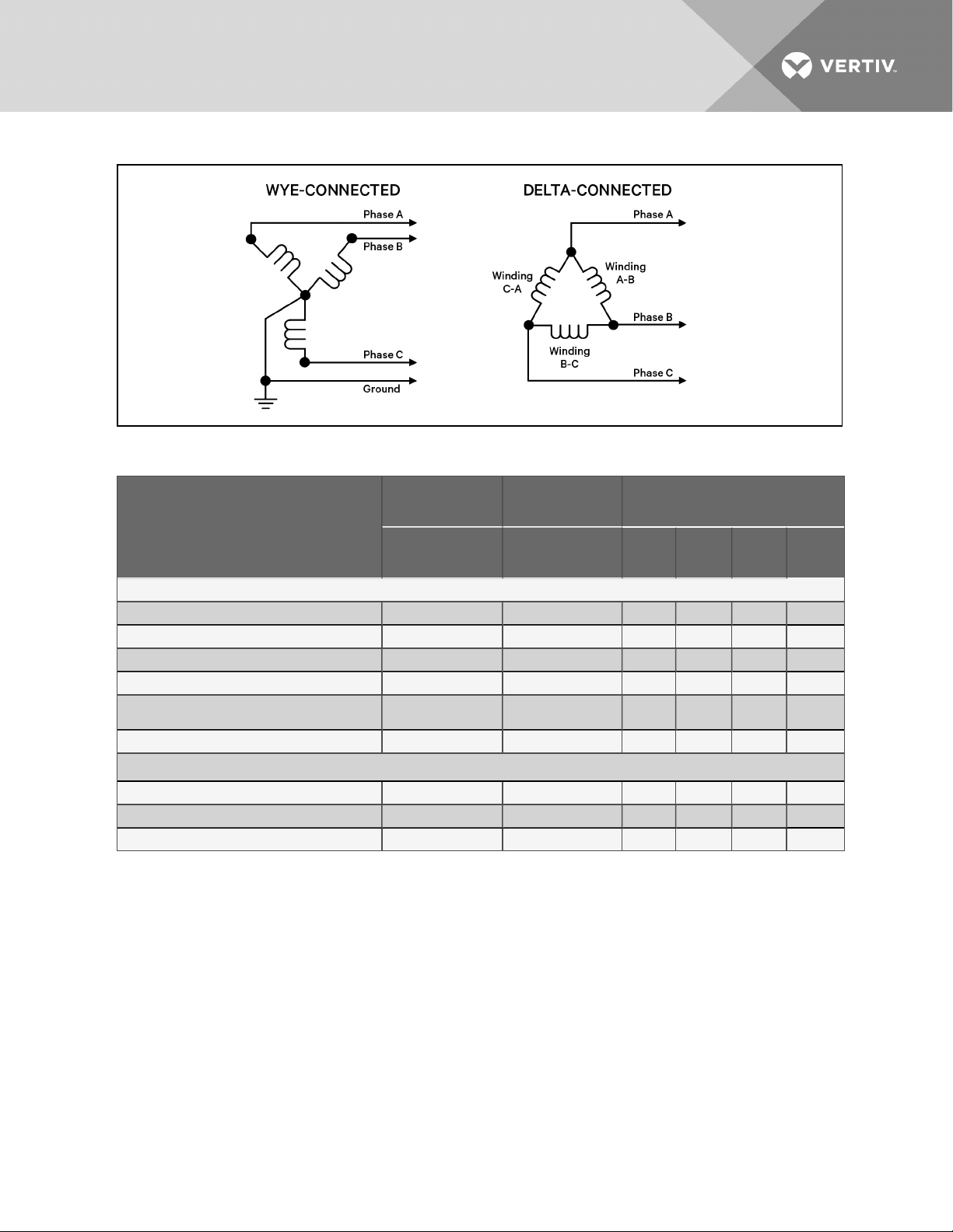
Figure 6.1 Wye- and Delta-connected power-suppy connection diagram
Table 6.2 Acceptable power supplies by nominal voltage and model
208V to 230V
nominal
PX011
PW011
Wye with solidly-groundedneutral:
208V Wye, 120V line-to-ground Yes Yes Yes Yes Yes Yes
230V Wye, 133V line-to-ground Yes Yes Yes Yes Yes Yes
380V Wye, 220Vline-to-ground Yes Yes Yes Yes Yes Yes
480 VWye, 277Vline-to-ground Yes Yes Yes Yes Yes Yes
575V Wye, 332Vline-to-ground
(usessteptransformers)
Wye with high-resistance (impedance) ground No No No No No No
Yes Yes Yes Yes Yes Yes
380V to 575V
nominal
PX011
PW011
208V to 575V nominal
PX018 PW017 PX023
PX029
PW029
Delta:
without groundor floating ground Yes No Yes Yes Yes Yes
withcorner ground Yes No Yes Yes Yes Yes
withgrounded center tap Yes No Yes Yes Yes Yes
NOTE: A 3-Phase, Wye-connected system consists of 3 hot lines or phases (commonly referred to as
X, Y, Z,) and a ground wire, for a total of 4 wires in a power-distribution cable. The lower voltage in each
case is the country’s standard utilization voltage and is measured Line-to-Neutral, while the higher
voltage is measured Line-to-Line. The Line-to-Line voltage is always 1.732 times higher than the Lineto-Neutral voltage in a Wye-configured 3-Phase system.
A 3-Phase, Delta-connected system consists of 3 hot lines (commonly referred to as phase A, phase B,
phase C,) and a ground wire for a total of 4wires in a power-distribution cable. These phase voltages
are measured Line-to-Line and are typically the country’s standard utilization voltage. Because there is
no neutral line in a Delta-connected system, there is no Line-to-Neutral voltage! However, the line
current in a Delta-connected system is 1.732 times the phase current supplied to the load(s).
Vertiv | Liebert® PDX™ and PCW™Installer/User Guide | 53
Page 54

6.2 Supply Temperature Sensor
The Liebert iCOM™ is equipped with a supply (discharge) air temperature sensor. The sensor can be used
to provide a consistent supply-air temperature by adjusting the compressor capacity or chilled-water
valve position, or it can be for monitoring purposes only.
The supply sensor must be installed 5 to15 ft (1.5to4.5m) from the unit, in the discharge air, to provide an
accurate reading when iCOM is set-up for supply-air temperature monitoring, supply control, or supply
limit.
A 50ft (15m) extension cable is available if the sensor must be farther than 15ft (4.5m) from the Liebert
iCOM controller.
See the Liebert iCOM user manuals, SL-18841 and SL-18835, for more information on supply-airtemperature monitoring, control, or limit setup. The manuals are available at https://www.vertivco.com/enus/support/.
6.3 Return Air Sensor
6.3.1 Internal Temperature/Humidity Sensor
The unit is supplied with a return-air sensor to measure return-air temperature and humidity conditions.
Liebert iCOM uses this information for many critical unit-control and system-monitoring functions. The
sensor is factory-installed internal to the unit in the return air stream.
6.3.2 Remote Temperature/Humidity Sensor
The unit can be configured for a remote temperature/humidity sensor, which is shipped loose for field
mounting. Sensor wire must be plugged into P66 on the iCOM control board, which is mounted inside the
unit control-and-monitoring section. Wire-length options are 30ft (9m), 60ft (18m), 90ft (27m), 120ft
(36m), or 150ft (45m). The internal return-air temperature/humidity sensor is omitted from the unit.
6.4 2T Wired Remote Sensors
Up to 10 remote-sensor modules, installed in the monitored racks and connected to the cooling unit,
provide control and reference input to iCOM and building-management systems. Using remote, rack
sensors combats cooling problems related to recirculation air, uneven rack loading, and air distribution.
The sensor array consists of 2T sensors that each have two temperature probes on a 6-ft (1.8-m) probeconnection cable.
Refer to the installation instructions included with the sensors or the hardware-installation section of the
Liebert iCOM user's manual, SL-18835, included with the system, for detailed installation and operating
configuration of the 2Track temperature sensors.
Figure 6.2 on the facing page shows the a typical sensor installation on racks that share a common cold
aisle and a single CRAC unit.
Vertiv | Liebert® PDX™ and PCW™Installer/User Guide | 54
Page 55
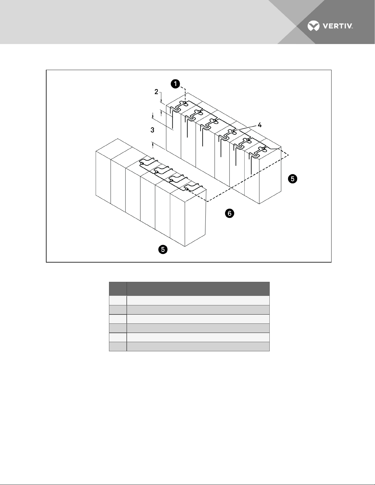
Figure 6.2 Rack sensor placement
Table 6.3 Sensor descriptions
Item Description
1 To cable entry incooling unit
2 First probe, 1 2in. ( 305mm) from top
3 S econd probe, in approximate center of rack andin front of the equipment
4 2T sensor with label visible
5 Hot aisle
6 Coldaisle
Vertiv | Liebert® PDX™ and PCW™Installer/User Guide | 55
Page 56

This page intentionally left blank.
Vertiv | Liebert® PDX™ and PCW™Installer/User Guide | 56
Page 57

7 CHECKLIST FOR COMPLETED INSTALLATION
7.1 Moving and Placing Equipment
1. Unpack and check received material.
2. Proper clearance for service access has been maintained around the equipment.
3. Equipment is level and mounting fasteners are tight.
7.2 Electrical Installation Checks
1. Supply voltage and phase matches equipment nameplate.
2. Power wiring connections completed to the disconnect switch, evaporator unit and heat
rejection equipment.
3. Power line circuit breakers or fuses have proper ratings for equipment installed.
4. Control wiring connections completed between indoor evaporator and heat-rejection
equipment.
5. All internal and external high- and low-voltage wiring connections are tight.
6. Confirm that unit is properly grounded to an earth ground.
7. Control transformer setting matches incoming power.
8. Electrical service conforms to national and local codes.
9. Check blowers and compressors for proper rotation.
10. Check for loose electrical connections on steam generating humidifier. Confirm that electrode
plugs are pressed firmly onto the electrode pins.
7.3 Piping Installation Checks
1. Piping completed to coolant loop (if required).
2. Piping has been leak-checked, evacuated and charged (if required).
3. Additional oil has been added for system charges over 40 pounds (18.1kg) per circuit. See
Table 5.8 on page37.
4. Piping is properly sized, sloped and trapped as shown in the piping schematics.
5. Check piping inside and outside of equipment for proper support and adequate spacing to
prevent rub-through.
6. Ensure TXV equalizer lines and sensing bulb lines have sufficient clearance and do not rub
against other refrigerant lines.
7. Ensure units with EEV have a receiver installed/piped on the Liebert MC and receiver is
mounted at or above the relative height of the EEV in the PDX unit.
8. Ensure that factory clamps have been reinstalled.
9. Drain line connected, not obstructed, and pitched per local code.
10. Water supply line connected to humidifier and not leaking.
11. Water/Coolant fluid supply and condensate drain line piping has no leaks or visible damage.
Vertiv | Liebert® PDX™ and PCW™Installer/User Guide | 57
Page 58

7.4 Other Installation Checks
1. Ducting complete (if required), maintain access to filters.
2. Filters installed.
3. Check fasteners that secure compressors, reheats, humidifier and motors—some may have
become loose during shipment.
4. Verify water detection is properly installed around all units (recommended).
5. Humidifier control-panel DIP switches are set based on user requirements.
6. Blower drive system rotates freely.
7. All fans are free of debris.
8. Remove rubber band from float in optional infrared humidifier.
9. Seal openings around piping and electrical connections.
10. Installation materials and tools have been removed from equipment (literature, shipping
materials, construction materials, tools, etc.).
Vertiv | Liebert® PDX™ and PCW™Installer/User Guide | 58
Page 59

8 INITIAL START-UP CHECKS ANDCOMMISSIONING
PROCEDUREFORWARRANTYINSPECTION
WARNING! Arc flash and electric shock hazard. Open all local and remote electric power-supply
disconnect switches, verify with a voltmeter that power is Off and wear appropriate,
OHSA-approved personal protective equipment (PPE) per NFPA 70E before working within the
electric control enclosure. Failure to comply can cause serious injury or death. Customer must
provide earth ground to unit, per NEC, CEC and local codes, as applicable. Before proceeding
with installation, read all instructions, verify that all the parts are included and check the
nameplate to be sure the voltage matches available utility power. The Liebert controller does
not isolate power from the unit, even in the “Unit Off” mode. Some internal components require
and receive power even during the “Unit Off” mode of the controller. The factory-supplied
disconnect switch is inside the unit. The line side of this switch contains live high-voltage. The
only way to ensure that there is NO voltage inside the unit is to install and open a remote
disconnect switch. Refer to unit electricalschematic. Follow all local codes.
WARNING! Risk of improper wiring, piping, moving, lifting and handling. Can cause equipment
damage, serious injury or death. Installation and service of this equipment should be done only
by qualified personnel, wearing appropriate, OSHA-approved PPE, who have been speciallytrained in the installation of air-conditioning equipment.
NOTICE
CAUTION: Risk of smoke generation. Can cause fire suppression and alarm system activation,
resulting in injury during building evacuation and mobilization of emergency fire and rescue
services. Start-up operation of optional electric reheat elements can create smoke or fumes
that can activate the facility alarm and fire suppression system. Prepare and take appropriate
steps to manage this possibility. Activating reheat during initial start-up may burn off
particulates from electric reheat elements. Check the steam generating humidifier electrode
plugs to ensure that they are pressed firmly onto the pins. Loose connections will cause the
cylinder and plugs to overheat. Before beginning initial start-up checks, make certain that unit
was installed according to the instructions in this manual. All exterior panels must be in place.
Risk of improper electrical connection of three-phase input power. Can cause backward
compressor rotation and unit damage. Service technicians should use a gauge set on the
system during the initial start up to verify that the three-phase power is connected properly.
The EC fans are not a reliable indicator of proper connection. The blowers will rotate the same
direction, regardless of the three-phase power input. Three-phase power must be connected
to the unit line voltage terminals in the proper sequence so that the compressors rotate in the
proper direction. Incoming power must be properly phased to prevent compressors from
running backward. We recommend checking the unit’s phasing with proper instrumentation to
ensure that power connections were made correctly. We also recommend verifying discharge
and suction pressures during start up to ensure that the compressors are running in the
correct direction.
Vertiv | Liebert® PDX™ and PCW™Installer/User Guide | 59
Page 60

• Confirm that all items on Checklist for Completed Installation on page57 have been done.
• Locate “Liebert PDX and Liebert PCW Warranty Inspection Check Sheet” in the unit’s electric
panel. (PSWI-8542-425-CO).
• Complete “Liebert PDX and Liebert PCW Warranty Inspection Check Sheet” during start-up.
(PSWI-8542-425-CO).
• Forward the completed “Liebert PDX and Liebert PCW Warranty Inspection Check Sheet” to
your local sales office. This information must be completed and forwarded to validate warranty.
• Contact your local sales representative or technical support if you have any questions or
problems during unit start-up and commissioning. Visit https://www.vertivco.com/enus/support/ or call 1-800-543-2778 for contacts.
Local sales offices and product support contacts can be found at https://www.vertivco.com/enus/support/ or 1-800-543-2778.
Vertiv | Liebert® PDX™ and PCW™Installer/User Guide | 60
Page 61

9 MAINTENANCE
WARNING! Arc flash and electric shock hazard. Open all local and remote electric power-supply
disconnect switches, verify with a voltmeter that power is Off and wear appropriate,
OHSA-approved personal protective equipment (PPE) per NFPA 70E before working within the
electric control enclosure. Failure to comply can cause serious injury or death. Customer must
provide earth ground to unit, per NEC, CEC and local codes, as applicable. Before proceeding
with installation, read all instructions, verify that all the parts are included and check the
nameplate to be sure the voltage matches available utility power. The Liebert controller does
not isolate power from the unit, even in the “Unit Off” mode. Some internal components require
and receive power even during the “Unit Off” mode of the controller. The factory-supplied
disconnect switch is inside the unit. The line side of this switch contains live high-voltage. The
only way to ensure that there is NO voltage inside the unit is to install and open a remote
disconnect switch. Refer to unit electricalschematic. Follow all local codes.
WARNING! Risk of electric shock. Can cause equipment damage, injury or death. Open all local
and remote electric power supply disconnect switches and verify with a voltmeter that power is
off before working within any electric connection enclosures. Service and maintenance work
must be performed only by properly trained and qualified personnel and in accordance with
applicable regulations and manufacturers’ specifications. Opening or removing the covers to
any equipment may expose personnel to lethal voltages within the unit even when it is
apparently not operating and the input wiring is disconnected from the electrical source.
WARNING! Risk of improper wiring, piping, moving, lifting and handling. Can cause equipment
damage, serious injury or death. Installation and service of this equipment should be done only
by qualified personnel, wearing appropriate, OSHA-approved PPE, who have been speciallytrained in the installation of air-conditioning equipment.
The LiebertPDX/PCW are single components in the facility heat-removal system. The system includes air
distribution (raised floors, duct systems), outdoor heat rejection (condensers, pumps, drycoolers) and
indoor cooling and humidity loads (equipment load, location, outside air infiltration). Proper application
and maintenance of the entire system is critical to the life and reliability of the thermal-management
units.
• Good maintenance practices are essential to minimizing operation costs and maximizing
product life.
• Read and follow monthly and semi-annual maintenance schedules included in this manual.
These MINIMUM maintenance intervals may need to be more frequent based on site-specific
conditions.
• See the Liebert® iCOM™ user manual, SL-18841, for instructions on using the controller to
predict some service maintenance intervals.
• We recommend the use of trained and authorized service personnel, extended service
contracts and factory-specified replacement parts. Contact your Vertiv™ sales representative.
Vertiv | Liebert® PDX™ and PCW™Installer/User Guide | 61
Page 62
9.1 Filters
NOTICE
Risk of improper filter installation. Can cause filter collapse and airflow reduction.
To maximize the performance and reliability of the equipment, use only Vertiv™ filters. Contact your
Vertiv™ representative to order replacement filters.
Verify that filters are installed and positioned so the air-flow direction marked on the filter is the same
direction as unit air flow.
Table 9.1 Filters, number and size
011, 01 7, 018, 023, 029
Downflow Models
Quantity 1
Nominal Size, inches 29.5 x 28.5 x 2
Upflow Models
Quantity 1
Nominal Size, inches 34 x 28 x 2
Disposable Type - Nominal sizes and number required, Standard
MERV 8 or Optional MERV 11
9.1.1 Filter-replacement for Downflow Units
1. Disconnect power from the unit.
2. Open the front access panel, locate the filter above the electric panel, and slide the filter out
the front of the unit.
3. Replace with new filter—install the filter in the proper direction of the airflow.
4. Test the operation of the filter clog switch.
The unit panels must be in place and closed to find this point.
5. Start the blower and turn the switch counterclockwise until the alarm is energized.
6. Turn the adjusting knob one turn clockwise or to the desired filter change point.
9.1.2 Filter-replacement for Upflow Units
1. Disconnect power from the unit.
2. Open the front access panel and remove the filter.
3. Replace with new filter—install the filters in the proper direction of the airflow. The proper
direction is marked on the filter.
4. Test the operation of the filter clog switch.
The unit panels must be in place and closed to find this point.
5. Start the blower and turn the switch counterclockwise until the alarm is energized.
6. Turn the adjusting knob one turn clockwise or to the desired filter change point.
Vertiv | Liebert® PDX™ and PCW™Installer/User Guide | 62
Page 63

9.1.3 Filter-replacement for Upflow Units with Rear Return
1. Disconnect power from the unit.
2. Open the front access panel from the floor stand, locate the filter, and slide the filter out the
front of the floor stand.
3. Replace with new filter—install the filter in the proper direction of the airflow.
4. Test the operation of the filter clog switch.
The unit panels must be in place and closed to find this point.
5. Start the blower and turn the switch counterclockwise until the alarm is energized.
6. Turn the adjusting knob one turn clockwise or to the desired filter change point.
9.2 Blower Drive System—EC Fans
WARNING! Risk of electric shock. Can cause serious injury or death. Open all local and remote
electric power-supply disconnect switches and verify with a voltmeter that power is off before
opening the fan motor electric-connection enclosure. Use only fully-trained and qualified HVAC
technicians to replace or perform maintenance on the EC fans.
CAUTION: Risk of contact with hot surfaces. Can cause burn injury. The EC fans, electronics
housing, humidifier pan and water contained within are extremely hot during operation. Allow
sufficient time for them to cool to a touch-safe temperature before handling. Use extreme
caution and wear appropriate, OSHA-approved PPE when replacing or performing maintenance
on the EC fans.
CAUTION: Risk of improper moving, lifting and handling. Can cause equipment damage or
injury. Only properly trained and qualified personnel should work on this equipment. Fan
modules weigh in excess of 125-lb (56.7-kg). Use proper lifting techniques and wear
appropriate, OSHA-approved PPE to avoid injury and dropping the fan module during removal.
Equipment used in handling/lifting, and/or installing the fan assembly must meet OSHA
requirements. Use handling/lifting equipment rated for the weight of the fan assembly. Use
ladders rated for the weight of the fan assembly and technicians if used during installation.
Refer to handling/lifting, and/or installation equipment operating manual for manufacturer's
safety requirements and operating procedures.
9.2.1 Fan Impellers and Bearings
Fan impellers should be periodically inspected and any debris removed. Check to ensure that the
impellers can rotate freely and that the fan guards are still properly mounted for sufficient protection
against accidentally contacting the impeller. Bearings used on the units are maintenance-free. Consult
the factory for more information.
Vertiv | Liebert® PDX™ and PCW™Installer/User Guide | 63
Page 64
9.2.2 Protective Features
Monitoring functions protect the motor against overtemperature of electronics, overtemperature of motor
and incorrect rotor position detection. With any of these failures, an alarm will display through the Liebert
iCOM controller and the motor stops electronically. There is no automatic restart. The power must be
switched off for a minimum of 20 seconds once the motor is at a standstill.
The motor also provides locked rotor protection, undervoltage/phase failure detection and motor current
limitation. These conditions will display an alarm through the Liebert iCOM.
9.2.3 Fan Assembly Troubleshooting
Any safety hazards stemming from the device must be re-evaluated once it is installed in the end device.
Do not make any modifications, additions or conversions to the fan assembly without the approval of
Vertiv™.
WARNING! Risk of electric shock. Can cause serious injury or death. Open all local and remote
electric power-supply disconnect switches and verify with a voltmeter that power is off before
opening the fan motor electric-connection enclosure. Use only fully-trained and qualified HVAC
technicians to replace or perform maintenance on the EC fans.
WARNING! Risk of contact with high-speed rotating fan blades. Can cause serious injury or
death. If control voltage is applied, the fan motor can restart without warning after a power
failure. Open all local and remote electric power-supply disconnect switches, verify with a
voltmeter that power is off, and verify that all fan blades have stopped rotating before working
on the fan assembly. After working on the fan assembly, remove any used tools or other
objects from the unit cabinet before restoring electric power.
CAUTION: Risk of exposure to harmful noise levels. Can cause hearing injury or loss.
Depending on the installation and operating conditions, a sound pressure level greater than
70dB(A) may arise. Take appropriate technical safety measures. Operating personnel must
wear appropriate, OSHA-approved PPE and observe all appropriate hearing-protection safety
requirements.
CAUTION: Risk of contact with hot surfaces. Can cause injury. The compressor, refrigerant
discharge lines, fan motor, and some electrical components are extremely hot during unit
operation. Allow sufficient time for them to cool to a touch-safe temperature before working
within the unit cabinet. Use extreme caution and wear appropriate, OSHA-approved PPE when
working on or near hot components.
NOTE: Do not assume that the fan blades will not start to spin. If the motor is in a fault condition, it will
safely shut down. Once the fault condition is cleared, there are certain conditions in which the motor
will automatically resume operation.
NOTE: Further troubleshooting procedures relating to fan connection/operation in the thermal
management unit are included in Blower troubleshooting.
Vertiv | Liebert® PDX™ and PCW™Installer/User Guide | 64
Page 65
EC-fan Fault Conditions
Table 9.2 EC-fan Fault Conditions
Fault
Condition
Phase Failure Automatic
Locked/Blocked
Rotor
Hall Effect
Sensor Error
Motor Over
Temperature
Electronics
Over
Temperature
Line
Under-Voltage
Reset Trigger Description
One phase is missing. Inthis case the motor will come toa stopand then automatically restart whenall phases
are present.
Automatic The rotor is blocked. Once the locking mechanism has been removed, the motor will automatically r estart.
Manual
(Mains/S oftware)
Manual
(Mains/S oftware)
Manual
(Mains/S oftware)
Automatic Once the line voltage returns within permittedoperating range, the fan willautomatically res tart.
The Hall EffectSensor is used to monitor fan speed. If there is a hall sensor communicationfailure with the
electronics, the motor will s top. In this case there has to be a manual restart (either withthe mains power or
software).
The motor wills top in the event there is a motor over temperature condition. In this case there has to be a
manual restart (either with the mains power or software).
The motor wills top in the event there is an electronics over temperature condition. In this case there has to be
a manual r estart (either withthe mains power or software) .
EC-fan High-voltage Tests
1. Check Fuses. If fuses are okay, perform the following:
• Check all connections.
• Make sure connections are on the wire strand and not on the wire insulation.
• Cycle Power. Disconnect mains voltage to power down the motor and then re-apply
power.
• Check mains voltage at each phase (phase to ground) at the KL1 connector.
Confirm phase failure not present.
• Check that the voltage is within the acceptable voltage range at the KL1
connector. Confirm line under-voltage is not present.
2. Check Fuses. If fuses are blown, perform the following:
• Check resistances across the phases at the KL1 connector and note them in the
following table..
NOTE: Power wires must be removed from the motor for resistance test.
L1 - L2 Ohm
L2 - L3 Ohm
L1 - L3 Ohm
• Resistances should be similar for all 3 readings.
Vertiv | Liebert® PDX™ and PCW™Installer/User Guide | 65
Page 66
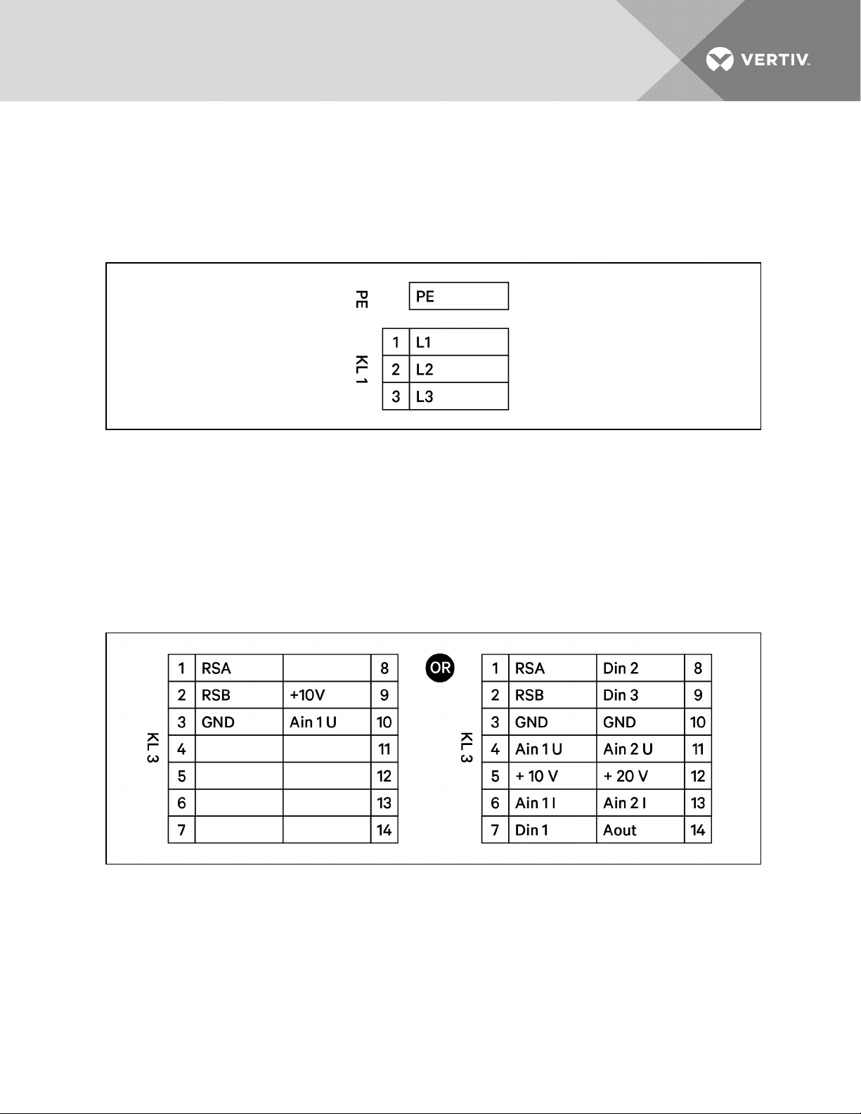
• Resistance readings should be greater than 2Ohm.
• Check all connections. Make sure connections are on the wire strand and not on
the wire insulation.
• Replace Fuses.
• Check mains voltage at each phase (phase to ground) at the KL1 connector.
Confirms phase failure not present.
• Check that the voltage is within the acceptable voltage range at the KL1
connector. Confirmsline under-voltage is not present.
EC-fan Low-voltage Tests
• Check control input at the KL3 connector (Ain1U to GND). Confirm that there is a
control voltage present at the KL3 connector.
NOTE: Use the GND in the KL3 connector. Do not connect the control ground to the PE in KL1!
• Check +10 V output on KL3 connector (between +10 V and GND).
Vertiv | Liebert® PDX™ and PCW™Installer/User Guide | 66
Page 67
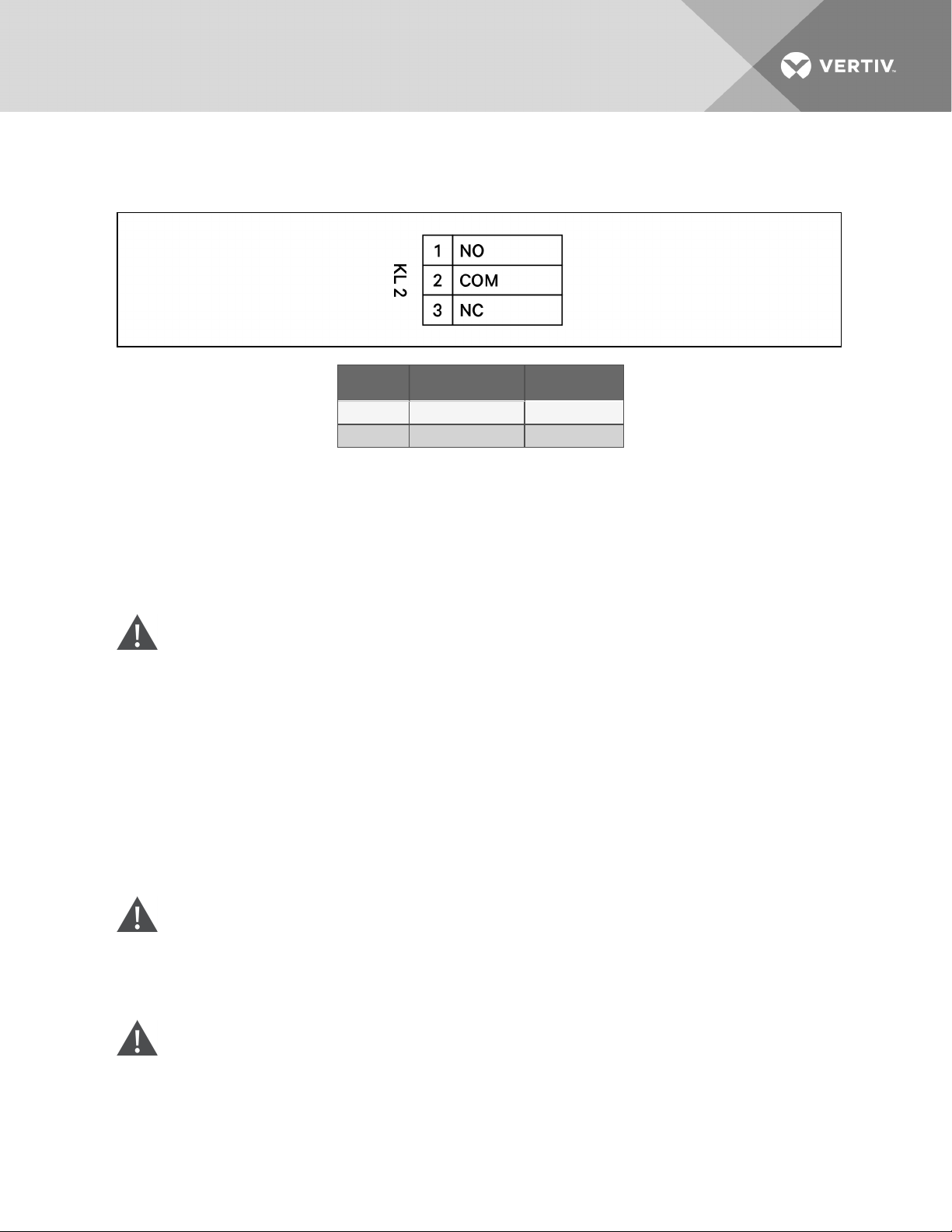
EC-fan Alarm Contact Tests
Check the alarm contact at KL2 to determine if there are any fault conditions present.
Condition No Fault C ondition Fault Condition
NO - COM Open Closed
NC - COM Closed Open
NOTE: The table refers to conditions while the motor is actively energized. When the motor is deenergized, it will be in a fault condition.
• Check EC Control to determine the fault condition.
9.2.4 Replacing EC Fans in Downflow Models
The EC-fan modules are removable for easier maintenance and replacement.
WARNING! Arc flash and electric shock hazard. Open all local and remote electric power-supply
disconnect switches, verify with a voltmeter that power is Off and wear appropriate,
OHSA-approved personal protective equipment (PPE) per NFPA 70E before working within the
electric control enclosure. Failure to comply can cause serious injury or death. Customer must
provide earth ground to unit, per NEC, CEC and local codes, as applicable. Before proceeding
with installation, read all instructions, verify that all the parts are included and check the
nameplate to be sure the voltage matches available utility power. The Liebert controller does
not isolate power from the unit, even in the “Unit Off” mode. Some internal components require
and receive power even during the “Unit Off” mode of the controller. The factory-supplied
disconnect switch is inside the unit. The line side of this switch contains live high-voltage. The
only way to ensure that there is NO voltage inside the unit is to install and open a remote
disconnect switch. Refer to unit electricalschematic. Follow all local codes.
WARNING! Risk of contact with high-speed, rotating fan impeller blades. Can cause injury or
death. Open all local and remote electric power-supply disconnect switches, verify with a
voltmeter that power is off, and verify that all fan impellers have stopped rotating before
working in the unit cabinet.
WARNING! Risk of very heavy fan module dropping downward suddenly. Can cause injury or
death. Only properly trained and qualified personnel should work on this equipment. The fan
module weighs approximately 100 lb. (45.4 kg).
Vertiv | Liebert® PDX™ and PCW™Installer/User Guide | 67
Page 68
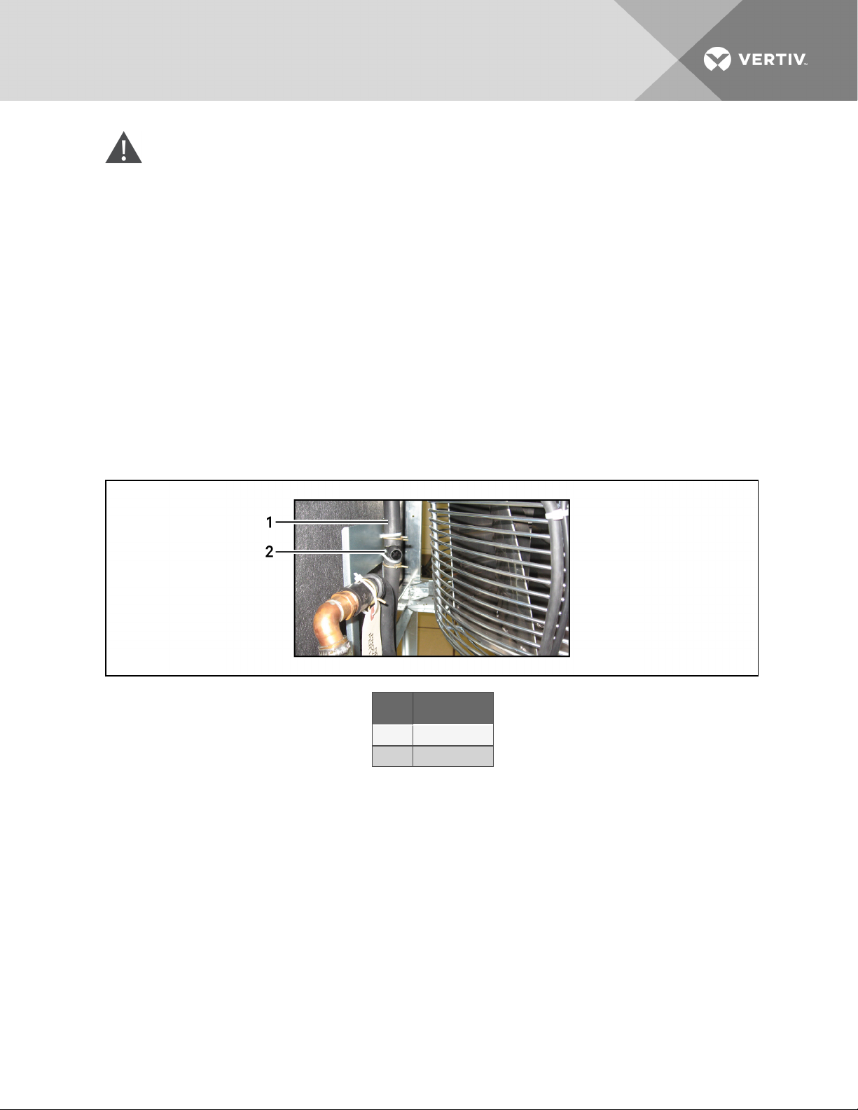
CAUTION: Risk of contact with hot surfaces. Can cause burn injury. The EC fans, electronics
housing, humidifier pan and water contained within are extremely hot during operation. Allow
sufficient time for them to cool to a touch-safe temperature before handling. Use extreme
caution and wear appropriate, OSHA-approved PPE when replacing or performing maintenance
on the EC fans.
To replace the fan(s):
1. Turn off the unit by touching “Turn Unit Off” in the iCOM menu and confirm in next screen by
touching “Turn Unit Off.”
2. Allow the unit shut down. Once shutdown is complete, turn the disconnect switch to the Off
position.
3. Open the front of the unit.
4. Remove the humidifier drain line by removing it from the T-connection on the left side of the
unit and disconnecting it from the humidifier pan. Then pull it up through the humidifier
air-blocking panel it passes through. See Figure 9.2 on the facing page.
Figure 9.1 Remove the humidifier drain line
Item Description
1 Humidifier drain
2 T-connection
Vertiv | Liebert® PDX™ and PCW™Installer/User Guide | 68
Page 69
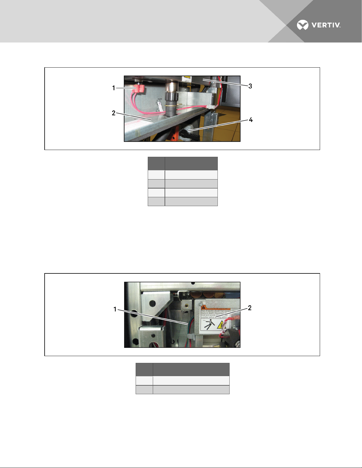
Figure 9.2 Remove humidifier high-limit wires
Item Description
1 Humidifier high-limitwires
2 Air- blocking panel
3 Humidifier pan
4 Actuator
5. Disconnect the actuator from the pipe beneath the right side of the humidifier (if present). See
Figure 9.2 above.
6. Remove the humidifier air block-off panel. See Figure 9.2 above.
7. Locate the humidifier assembly and remove the cover to the electrical compartment.
Disconnect the wires entering the humidifier electric box from the left side. See Figure 9.3
below.
Figure 9.3 Humidifier electric box location
Item Description
1 Humidifier wiring harness
2 Humidifier electric-compartment cover
Vertiv | Liebert® PDX™ and PCW™Installer/User Guide | 69
Page 70
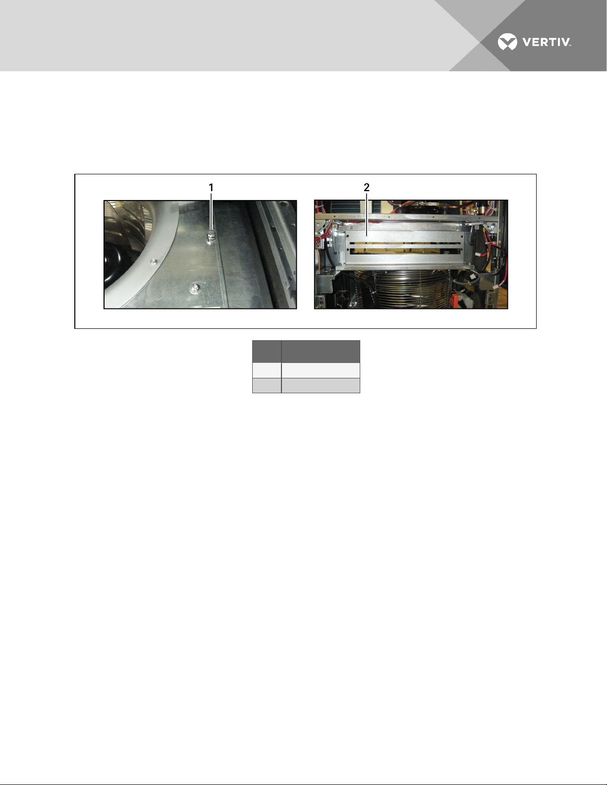
8. Remove the 4hex bolts securing the humidifier assembly to the unit, see Figure 9.4 below,
then remove the humidifier from the unit.
9. Remove the panel located behind the humidifier’s previous location. This will reveal the panel
and make it accessible. See Figure 9.4 below.
Figure 9.4 Bolt and panel removal
Item Description
1 Hex bolt(4 places)
2 Panel behindhumidifier
10. Remove the smoke detector tubing from the right side; remove the air sail tubing from the left
side.
11. Remove the high and low voltage wiring supplying the fan.
12. Remove the four hex bolts securing the mounting panel to the unit. Remove only the bolts
indicated in Figure 9.4 above.
13. Slide the EC fan assembly forward and out of the unit.
14. Place the new EC fan assembly in the unit on the mounting rails that supported the old
assembly.
15. Connect all high-voltage and low-voltage wiring.
16. Secure the new assembly using the same hardware removed in step 12.
17. Reattach smoke detector and air-sail tubing removed in step 10.
18. Reinstall the panel removed in step 9.
19. Reinstall the humidifier air-blocking panel removed in step 6.
20. Reinstall the humidifier assembly and reconnect the wire harness removed in step 8.
21. Run the drain humidifier drain that was removed in step 4 through the humidifier air-blocking
panel. Connect to the T-connection on the left side of the unit; reconnect the humidifier’s
high-limit wires to the bottom of the humidifier pan that were removed in step 5.
22. Reconnect the actuator (if present) that was removed in step 5.
23. Replace the front panel of the unit. Turn main disconnect to On. Turn unit On at display and
verify the new fan starts.
Vertiv | Liebert® PDX™ and PCW™Installer/User Guide | 70
Page 71
9.2.5 Replacing EC Fans in Upflow Models
The EC-fan modules are removable for easier maintenance and replacement.
WARNING! Arc flash and electric shock hazard. Open all local and remote electric power-supply
disconnect switches, verify with a voltmeter that power is Off and wear appropriate,
OHSA-approved personal protective equipment (PPE) per NFPA 70E before working within the
electric control enclosure. Failure to comply can cause serious injury or death. Customer must
provide earth ground to unit, per NEC, CEC and local codes, as applicable. Before proceeding
with installation, read all instructions, verify that all the parts are included and check the
nameplate to be sure the voltage matches available utility power. The Liebert controller does
not isolate power from the unit, even in the “Unit Off” mode. Some internal components require
and receive power even during the “Unit Off” mode of the controller. The factory-supplied
disconnect switch is inside the unit. The line side of this switch contains live high-voltage. The
only way to ensure that there is NO voltage inside the unit is to install and open a remote
disconnect switch. Refer to unit electricalschematic. Follow all local codes.
WARNING! Risk of contact with high-speed, rotating fan impeller blades. Can cause injury or
death. Open all local and remote electric power-supply disconnect switches, verify with a
voltmeter that power is off, and verify that all fan impellers have stopped rotating before
working in the unit cabinet.
WARNING! Risk of very heavy fan module dropping downward suddenly. Can cause injury or
death. Only properly trained and qualified personnel should work on this equipment. The fan
module weighs approximately 100 lb. (45.4 kg).
CAUTION: Risk of contact with hot surfaces. Can cause burn injury. The EC fans, electronics
housing, humidifier pan and water contained within are extremely hot during operation. Allow
sufficient time for them to cool to a touch-safe temperature before handling. Use extreme
caution and wear appropriate, OSHA-approved PPE when replacing or performing maintenance
on the EC fans.
To replace the fan(s):
1. Turn off the unit by touching “Turn Unit Off” in the iCOM menu and confirm in next screen by
touching “Turn Unit Off.”
2. Allow the unit to shut down. Once shutdown is complete, turn the main electrical disconnect
switch to the Off position.
3. Open the front of the unit.
Removing the side panels will assist in replacing the fan, but it is not necessary.
4. Remove the high- and low-voltage wiring connections to the fan.
5. Remove the 4 bolts that secure the fan assembly to the unit. These bolts are front-accessible,
with 2on the left side and 2on the right side. The bolts on one side are shown in Figure 9.5 on
the next page.
Vertiv | Liebert® PDX™ and PCW™Installer/User Guide | 71
Page 72

Figure 9.5 Mounting-plate bolt location
Item Description
1 Orifice mounting plate
6. Locate the 4 bolts on the intake-orifice mounting plate, and example is shown in Figure 9.6
below. These bolts are front-accessible with 2on the left side and 2on the right side of the
plate.
7. Loosen these 4 bolts and lower the orifice mounting plate so that it rests on the brackets, one
of the brackets is shown in Figure 9.6 below.
Figure 9.6 Bolts to loosen and Brackets on which the plate will rest
Item Description
1 Bolt on mounting plate to loosen
2 Bracket onwhich mounting plate will r est
Vertiv | Liebert® PDX™ and PCW™Installer/User Guide | 72
Page 73
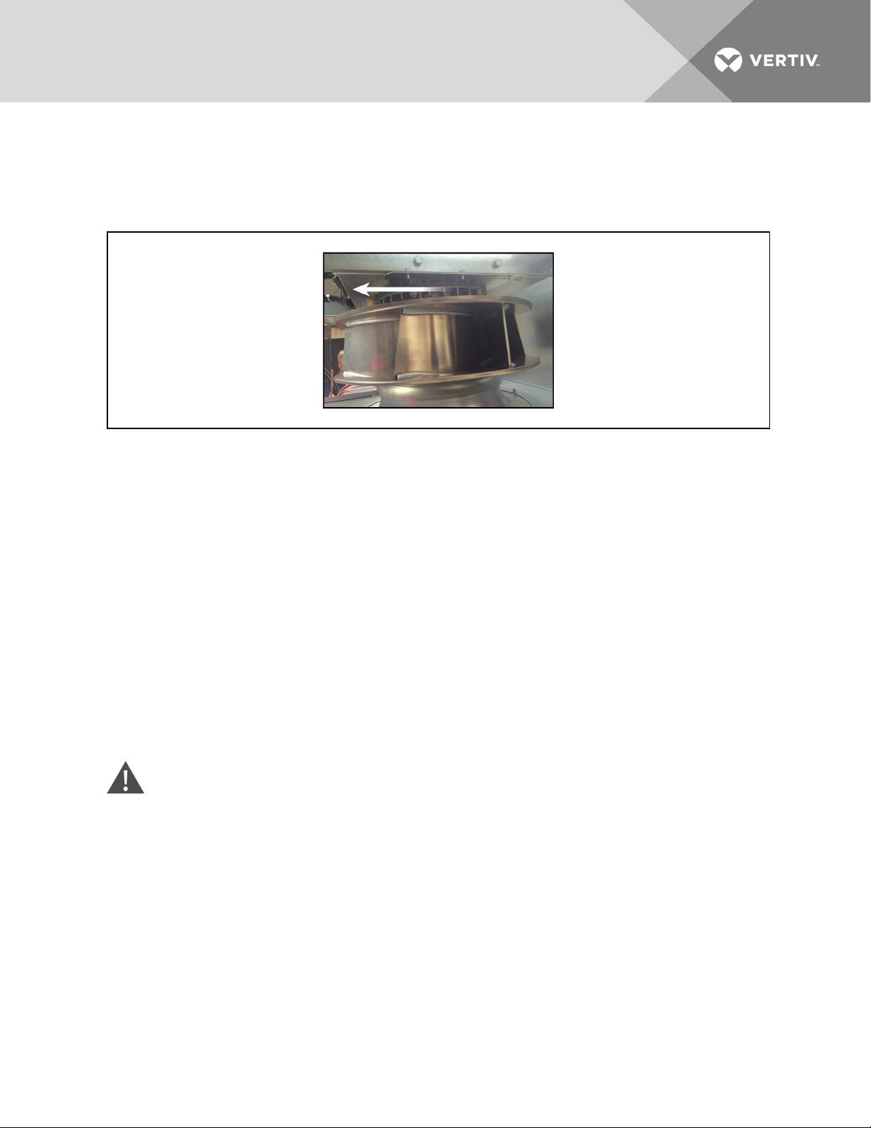
8. With the mounting plate lowered, remove the fan from the unit by sliding it forward on the rails
as shown in Figure 9.7 below. Take note of how the fan slid from the unit.
9. A service loop has been added to the wire harness, cut the wire ties to loosen.
Figure 9.7 Slide the fan assembly out the front of the unit
10. Slide the new fan assembly into place along the guide rails until it is in the correct position.
11. Re-install the bolts that were removed in step 5 to secure the fan assembly to the unit.
12. Tight the bolts that were loosened in step 7 to raise the mounting plate back into position.
13. Close the unit and re-install any panels that were removed.
14. Turn main electrical disconnect to On, turn the unit On at the iCOM display.
15. Place the unit into a call for cooling and verify that the new fan starts.
9.3 Infrared Humidifier Maintenance
During normal humidifier operation, deposits of mineral solids will collect in humidifier pan and on the float
switch. These must be cleaned periodically to ensure proper operation. Frequency of cleaning must be
locally established since it is dependent on humidifier usage and local water quality. A spare pan is
recommended to reduce maintenance time at unit. The Liebert autoflush system can greatly increase the
time between cleanings, but does not eliminate the need for periodic checks and maintenance (see
Liebert iCOM™ user manual SL-18841 for autoflush setup). To help reduce excessive scaling in locations
with difficult water quality, the use of Vapure™ is recommended (contact your local sales representative).
CAUTION: Risk of contact with extremely hot water and part surfaces. Can cause burn injury.
The infrared humidifier bulbs, metal enclosure, humidifier water, water reservoir pan and drain
tubing are very hot during and shortly after operation. Allow sufficient time for these parts to
cool to a touch-safe temperature before handling. Use extreme caution, and wear appropriate,
OSHA-approved PPE when performing maintenance on the infrared humidifier.
9.3.1 Cleaning Humidifier Pan and Float Switch
Before turning the unit Off:
1. With unit operating, remove call for humidification at the Liebert iCOM control.
2. Let the blower operate 5 minutes to allow the humidifier and water to cool.
3. If unit has a condensate pump, turn unit OFF at Liebert iCOM control.
4. Pull out the humidifier standpipe in pan.
Vertiv | Liebert® PDX™ and PCW™Installer/User Guide | 73
Page 74
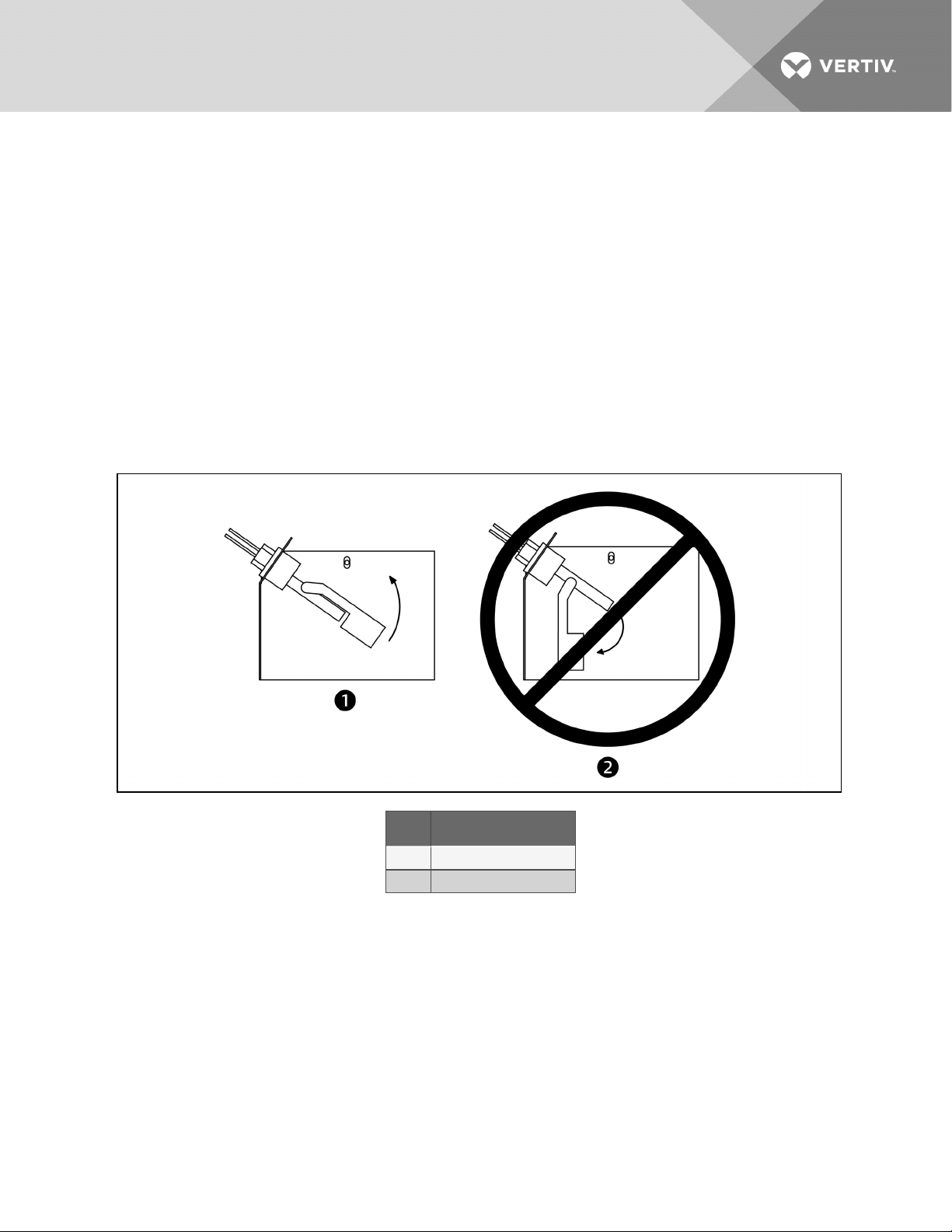
5. Inspect the O-ring (replace if necessary).
6. Let the pan drain and condensate pump operate (if applicable).
7. Disconnect power from the unit.
8. Disconnect the drain coupling from the bottom of the pan.
9. Remove the thermostat from the bottom of the pan and the retaining screws from the sides of
the pan.
10. Slide the pan out.
11. Loosen scale on side and bottom of pan with a stiff nylon brush or plastic scraper.
12. Flush with water.
13. Carefully clean scale off float switch (make sure to reinstall correctly (see Figure 9.8 below).
14. Reinstall the pan, thermostat, standpipe, drain coupling and screws into the humidifier.
15. Operate the humidifier and check for leaks.
Figure 9.8 Correct float switch orientation
Item Description
1 Correct switchorientation
2 Incorr ect s witch orientation
9.3.2 Changing Humidifier Lamps
NOTE: Touching quartz lamps with bare hands will severely shorten bulb life. Skin oils create hot spots
on lamp surface. Wear clean cotton gloves when handling lamps.
The lamps are shown in Figure 9.9 on the facing page.
1. Remove humidifier pan (see Cleaning Humidifier Pan and Float Switch on the previous page,
steps 1 through 10).
2. Disconnect power from unit.
3. At humidifier, remove screws and cover from high-voltage compartment.
4. Disconnect one end of purple jumper wires.
Vertiv | Liebert® PDX™ and PCW™Installer/User Guide | 74
Page 75
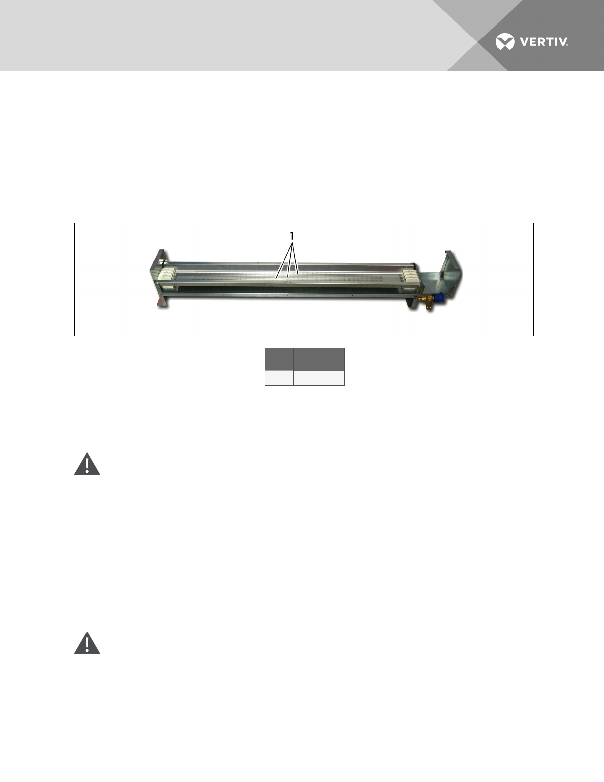
5. Using a continuity meter, locate burned out lamp.
6. Remove lamp brackets under lamps.
7. Loosen two screws securing lamp lead wires to junction block.
8. Pull bulb straight down and discard.
9. Wrap lead wires once around new lamp’s metal ends. This will support lamp and allow for
thermal expansion. Insert lead wires into junction block and torque screws to 30 in-lb.
10. Reassemble by reversing steps 1 through 9.
Figure 9.9 Infrared humidifier lamps
Item Description
1 Infrar ed bulbs
9.4 Steam-generating Humidifier Maintenance
The humidifier drains and refills to maintain a current setpoint and alert the operator when the humidifier
canister needs to be replaced.
WARNING! Arc flash and electric shock hazard. Open all local and remote electric power-supply
disconnect switches, verify with a voltmeter that power is Off and wear appropriate,
OHSA-approved personal protective equipment (PPE) per NFPA 70E before working within the
electric control enclosure. Failure to comply can cause serious injury or death. Customer must
provide earth ground to unit, per NEC, CEC and local codes, as applicable. Before proceeding
with installation, read all instructions, verify that all the parts are included and check the
nameplate to be sure the voltage matches available utility power. The Liebert controller does
not isolate power from the unit, even in the “Unit Off” mode. Some internal components require
and receive power even during the “Unit Off” mode of the controller. The factory-supplied
disconnect switch is inside the unit. The line side of this switch contains live high-voltage. The
only way to ensure that there is NO voltage inside the unit is to install and open a remote
disconnect switch. Refer to unit electricalschematic. Follow all local codes.
WARNING! Risk of improper wiring, piping, moving, lifting and handling. Can cause equipment
damage, serious injury or death. Installation and service of this equipment should be done only
by qualified personnel, wearing appropriate, OSHA-approved PPE, who have been speciallytrained in the installation of air-conditioning equipment.
Vertiv | Liebert® PDX™ and PCW™Installer/User Guide | 75
Page 76
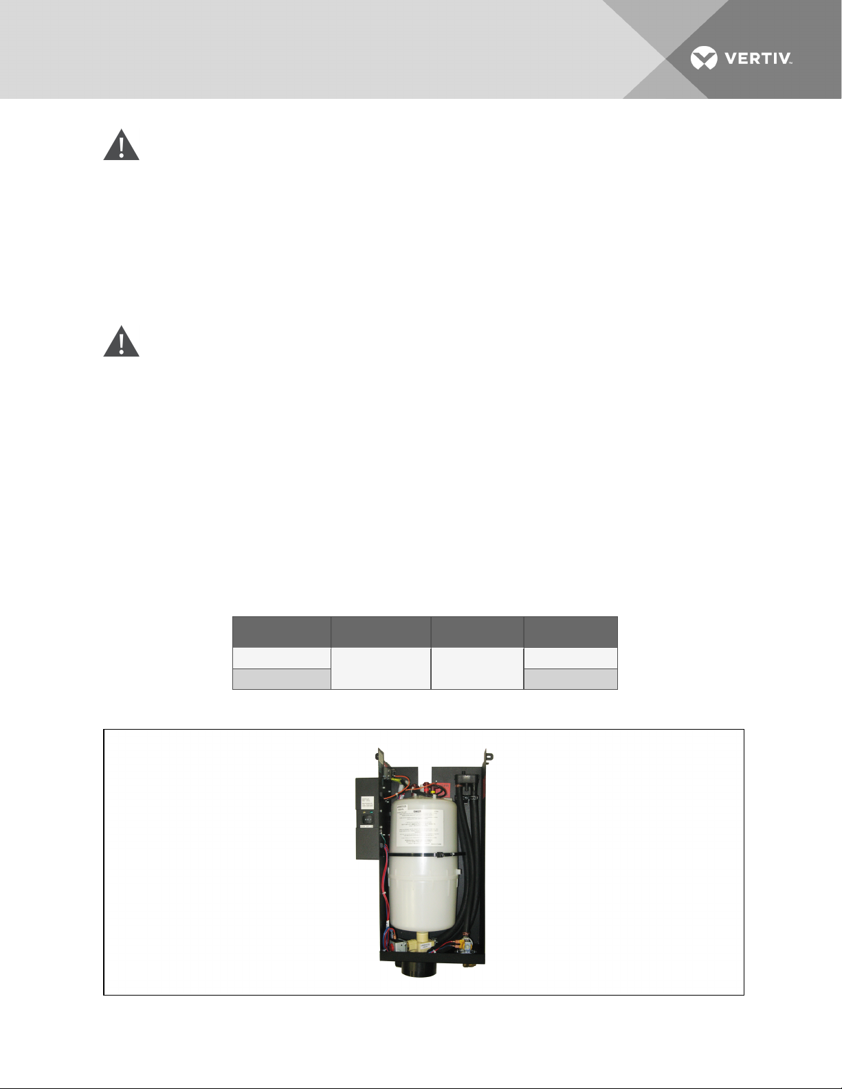
WARNING! Risk of improper humidifier-canister maintenance. Can cause smoke and fire,
activation of fire suppression systems, building evacuation, dispatching of fire/rescue
equipment and personnel, and catastrophic canister failure resulting in water leaks, equipment
damage, injury, or death. Using a humidifier canister that has reached the end of it’s service life
can be extremely hazardous. If the canister cannot be replaced immediately at the end of life
condition, turn Off the power and water supply to the humidifier and remove the canister until a
replacement canister can be installed. Do not ignore humidifier problem alarms. Resetting
humidifier without addressing cause may result in fire or damage due to leaking water. See
Table 9.4 on page80, for alarm corrective actions.
CAUTION: Risk of contact with hot surfaces. Can cause burn injury. The humidifier canister
and steam discharge lines are extremely hot during operation. Allow sufficient time for them to
cool to a touch-safe temperature before handling. Use extreme caution and wear appropriate,
OSHA-approved PPE when performing maintenance on the humidifier.
After an extended period of operation, in accordance with life-expectancy information, the cylinder is
completely used as indicated by the amber high-water sensor light illuminated on the cabinet. Then this
condition is reached, a new replacement cylinder must be installed.
NOTE: The amber high-water sensor light may come on during initial start-up, but this instance does
not indicate that the cylinder should be replaced.
The steam cylinder is disposable and must be replaced at the end of the cylinder's life. Cylinder life will
vary according to water-supply conditions and humidifier use.
Table 9.3 Humidifier canister part numbers
Unit Model 200V, 208V, 230V 380/41 5V, 460V Humidifier Model
PX011, 018, 023, 029
PW017, 029 MES 2
317911p1 317911p2
MES 2
Figure 9.10 Steam generating humidifier canister
Vertiv | Liebert® PDX™ and PCW™Installer/User Guide | 76
Page 77

9.4.1 Removing the Old Canister
To replace a used-up humidifier cylinder:
1. Turn Off the water supply to unit.
2. The old cylinder must be drained completely before removing. This is done by pushing the
auto On/Off/drain switch to the "Drain" position.
3. When completely drained, push the auto On/Off/Drain switch to the Off position.
4. Open the main electrical disconnect during the entire cylinder change operation.
5. The power wires to the cylinder are attached by cylinder plugs to the electrode pins on top of
the cylinder. Pull up to remove the plugs from the pins.
6. Use slotted screwdriver to loosen the steam hose clamp(s)
7. Disconnect the steam hose by pulling it straight up.
8. Loosen the reversible cylinder zip tie.
The cylinder is now ready to be lifted out of the unit.
9.4.2 Mandatory Cleaning of the Drain Valve
Always clean the drain valve before installing a new cylinder. Figure 9.11 on the next page shows an
exploded view of the drain valve for reference to clean it.
1. Remove old cylinder as described in Removing the Old Canister above.
2. Note that the ring terminal for the drain-valve green ground wire is sandwiched between the
drain valve and the drain pan.
3. Remove the two screws securing the drain valve body to the drain pan.
4. Remove the hose clip and hose connection from the drain-valve body.
5. The drain-valve assembly is now free for disassembly and cleaning.
6. At a sink, remove the snap-fit red cap from the coil assembly and slide the coil off the actuator.
7. Loosen actuator using a wrench and unscrew from the plastic body.
8. Clean the exposed core, spring and plastic drain-valve pot
9. Reinstall in the reverse order.
NOTE: Be cautious when putting the spring back into the plunger, the taper end of the spring must be
installed toward the solenoid.
10. Hand-tighten the actuator back into place, then secure it using a wrench to turn it a quarter of
a turn.
11. Clean out the end of the hose, then reconnect it to the drain-valve body with the clamp.
12. Fit mounting screws back through the drain-valve body, one through ring terminal on the
green wire.
Vertiv | Liebert® PDX™ and PCW™Installer/User Guide | 77
Page 78
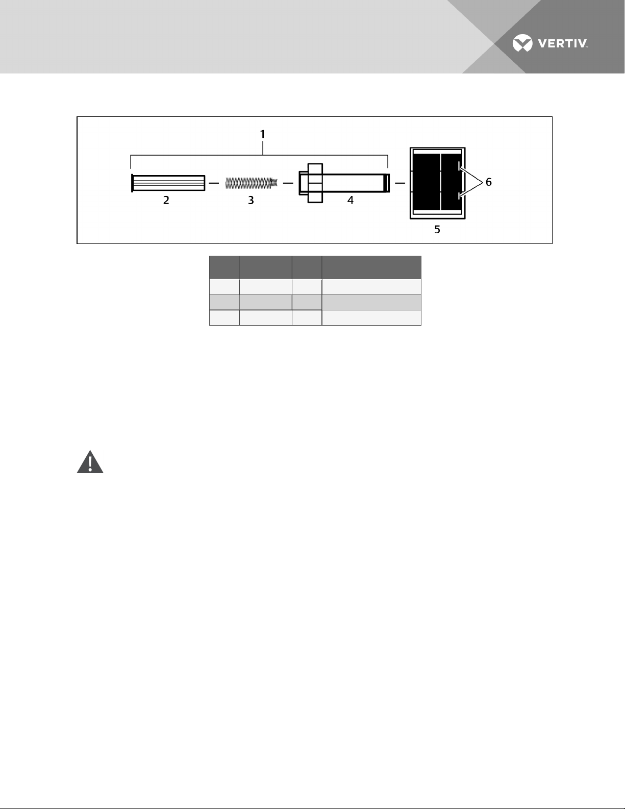
Figure 9.11 Drain valve assembly
Item Description Item Description
1 Actuator 4 Sleeve
2 Plunger 5 Holding coil
3 S pring 6 Male, slip-on connection tabs
9.4.3 Installing the New Canister
1. The reverse procedure should be followed to install a new cylinder. The main electrical
disconnect is to be left open until the cylinder is completely installed and reconnected.
2. The blue sensor plug on all units is for the high water sensor pin, which always goes on the
single pin with collar offset from the others. See Figure 9.12 on the facing page.
3. Ensure that cylinder plugs are snug on the pins. Replace any loose fitting plugs as these may
result in hazardous operation.
WARNING! Risk of humidifier canister meltdown, smoke and fire. Can cause fire suppression
system activation, fire and smoke alarm activation, building evacuation, dispatching of fire and
rescue equipment and personnel and water leaks resulting in expensive equipment or building
damage, injury or death. Check steam generating humidifier electrode plugs to ensure that they
are pressed firmly onto pins. Loose connections will cause overheating of cylinder and plugs.
Vertiv | Liebert® PDX™ and PCW™Installer/User Guide | 78
Page 79
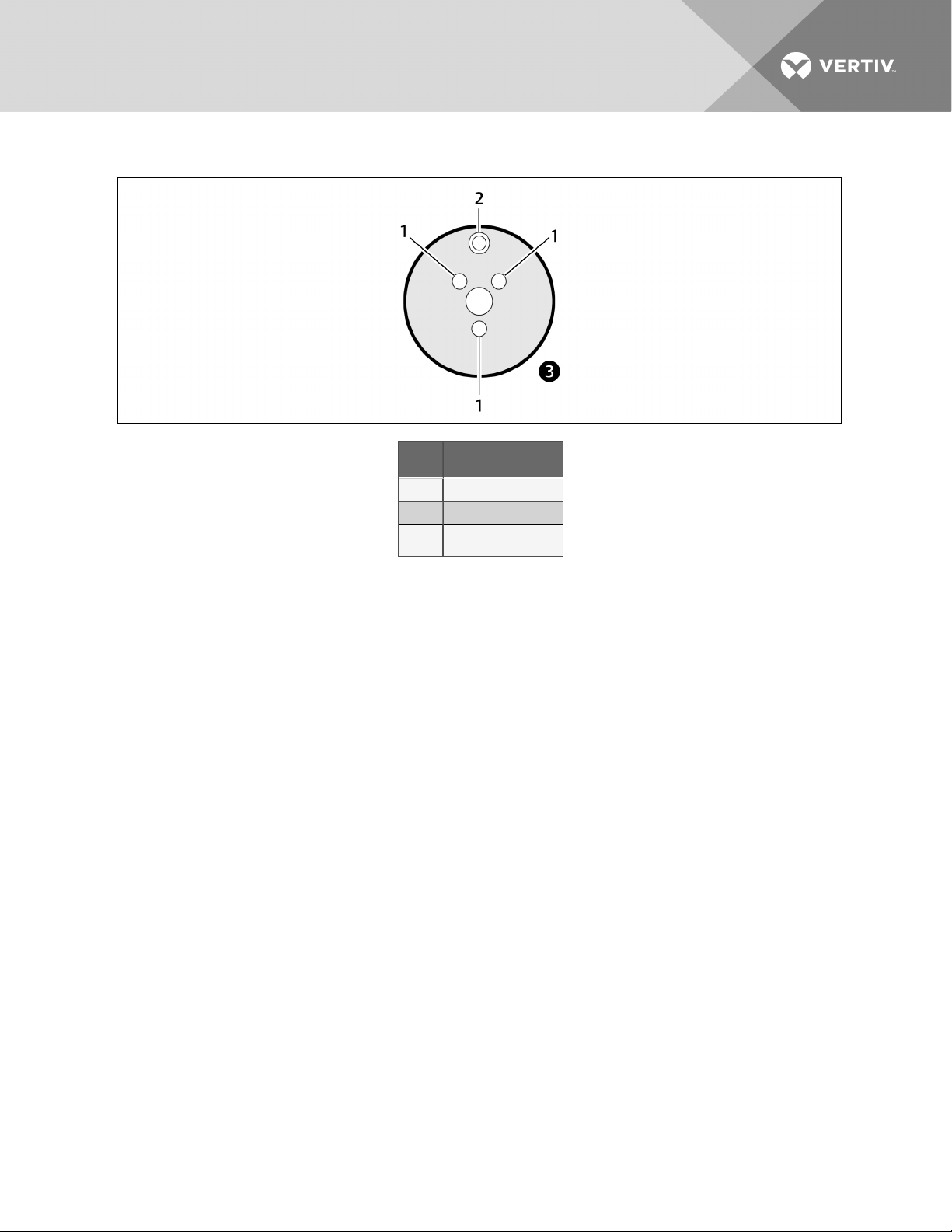
Figure 9.12 Canister plugs
9.4.4 Humidifier Troubleshooting
Item Description
1 Cylinder pin
2 High-water sensor pin
3
3 ∅
Terms Used in Humidifier Troubleshooting:
• FLA (Full Load Amps) are amps listed on the humidifier specification label.
• Short cycling occurs when the humidifier’s “On time” is less than 10 minutes upon a call for
humidity. To correct short cycling, all humidifiers have a capacity adjustment that allows the
output of the humidifier to be reduced to as low as 20% of rated output, thus extending the “on
time” required to maintain output.
• Foaming can occur when the impurities already in water reach an excess concentration as a
result of boiling away water and continued boiling agitates the contained water. The humidifier
electronics are designed to prevent foaming, although in extreme cases water will foam with
little concentration, making it necessary to increase the drain time of the water contained in
the cylinder. Foaming is normally caused by short cycling, a restricted drain or back pressure.
The foam generated in these instances is conductive and may lead to false full-cylinder
indication if the level of the foam approaches the top of the cylinder.
• Back pressure is the restriction of steam flow caused by long steam runs, improperly sloped
steam lines, elbows changing the direction of steam flow from horizontal to vertical without a
drain leg, any plumbing detail allowing the accumulation of condensate, undersized steam line,
improper steam distributor, downward air flow onto the distributor causing excess static
pressure at the steam outlets, or high static pressure ducts (not probable). To overcome
excess static pressure in the duct, use a fill cup extension kit. In downflow applications, a
downflow distributor should be used, but in some cases the fill cup extension will also be
required.
Vertiv | Liebert® PDX™ and PCW™Installer/User Guide | 79
Page 80
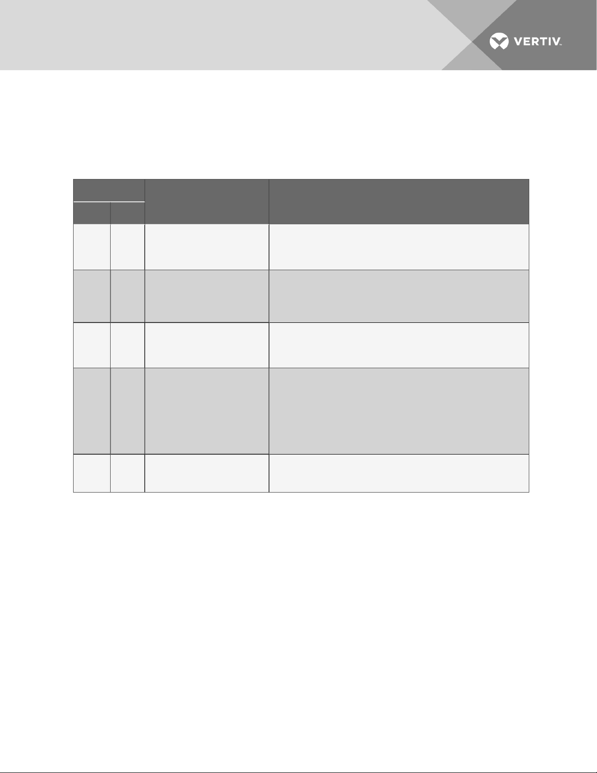
• Reset unit (humidifier): To reset the humidifier, switch the auto On/Off/Drain switch at the
front of the humidifier to the Off position for at least five seconds, then switch it back to the On
position.
• Monitored leg is the primary wire to the cylinder that loops through the current sensing device
of the main PCB. This wire ends at the red cylinder plug at the cylinder.
Table 9.4 Steam-generating Humidifier Status Lamps: Causes and Corrective Actions
Unit S tatusLamp
Symptom Corrective Actions
Yellow Green
This usually happens on initial start-up after replacing the cylinder (normal).
On On Maximum water level inside cylinder.
Off Off No power to the board.
1 flash
sequence
2 flashes
in
sequence
4 flashes
in
sequence
Off
Off
Off End of cylinder life - change cylinder.
Excess current. Operatingamperage
exceeded 130% of r ated amps. Water
is drained from the cylinder ( drain
valve on for 1 0 minutes).
No current detection for 30 minutes
withcontinuous call for humidity.
Water is concentratedwithminerals inside the cylinder.
Let unitrun; yellow lightwill disappear when the unit is at full output. This may take a
day or two.
Check for main power supply fault.
Turn power switch to "Drain" position. If drain valve is activated( sound of solenoid),
check connectionto the board or board itself.
Whenno sound is present, check fuse (replace with 3.0 A if needed), transformer
(voltage shouldbe present between fuse holder and groundscr ew).
Check drain valve operation, drain time, possible drain restrictions.
Check fill valve for leaks (not holding supply water).
Back pressure may also cause very conductive water conditions. Check for short
cycling. Water conductivity too high.
Check water level in the cylinder - should be more than 1/4 full. If not, check fill r ate,
24 VAC on fill valve terminals ( unitmust be onwithcall for humidity - green lighton
steadily). Verify fresh water s upply to the humidifier. Leaking drain valve may be at
fault( minerals blockingthe plunger).
If cylinder is more than1 /4 full, check primary power, connections to the cylinder,
continuity of wires tocylinder.
Are power wires connected to proper terminals on the cylinder? (Color coding.)
Possibly wrong cylinder type.
Low water conductivity.
Check water level in the cylinder; s houldbe about 3/4full.
Check for foaming if water level is lower or cylinder life s horter than expected.
Change cylinder, cleandrain valve.
Vertiv | Liebert® PDX™ and PCW™Installer/User Guide | 80
Page 81
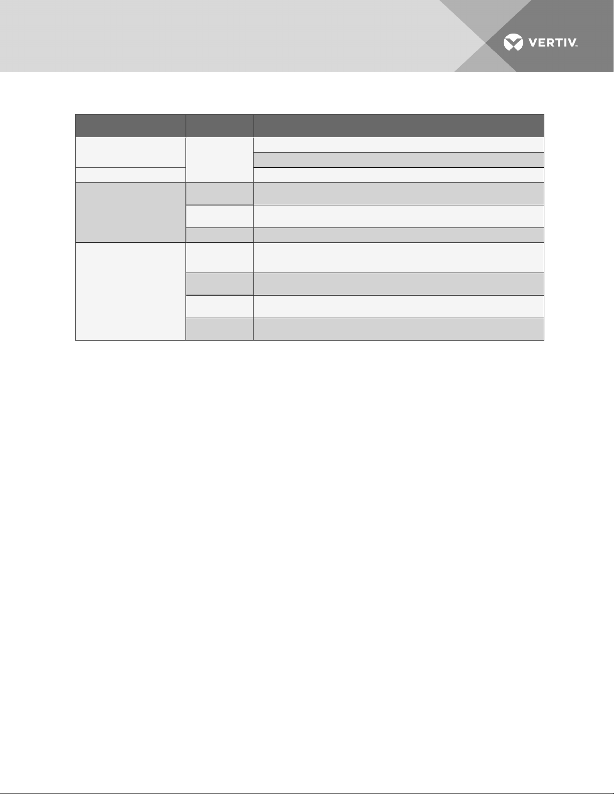
Table 9.5 Steam generating humidifier troubleshooting guide
Symptom Possible C ause Check or Remedy
Unit in call for humidification,
humidifier will not operate Humidifier not
Humidifier Contactor pulledin,
butno water enters canister
Excessive arcing in canister
receiving power
No water available
to unit
Cloggedfill line
strainer
Drain valve
clogged or
defective
Improper water
supply
Insufficientdrain
rate
Excessive mineral
content in water
Verify ON/OFF/DRAIN switch is in ON position.
Check fuses or CB's andr eplace or res et if necessar y.
Check external water shut-off valves.
Cleanor replacedfill line strainer
Verify that drain valve operates freely when activated. Clean valve and replace ifdefective.
Flush canister s everal times and replace if arcingpersists.
If water is commercially softened, r econnecthumidifier to raw water supply, drain canister
and res tart. If connected to hot water supply, reconnectto cold water.
Verify that drain valve operates freely when activated. Clean valve and replace ifdefective.
Flush canister s everal times and replace if arcingpersists.
Analyze mineral content of water. If mineral contentis excessive contact Vertiv™ Technical
Support.
Vertiv | Liebert® PDX™ and PCW™Installer/User Guide | 81
Page 82
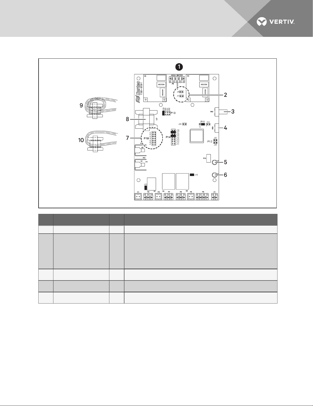
Figure 9.13 Steam-generating Humidifier Circuit board diagram
Item Description Item Description
1 PCB is configured for: MES-L 6 Yellow LED
HW Sensor Jumperss
2
Capacity adjust ( Default at
3
100%)
4 Sealed, do not adjust 9
5 Green LED 10
• J9: Low Voltage
200-24 0V
• J8: High Voltage
380-600V
Mains Voltage Select Jumpers
• J6: 200-208
7
8 Current transformer
Current Transformer for MES-L 10, loopcurrent-sensingwire twice through current s ensing
coil.
Current transformer for MES-L20, loop curr ent-sensing wire once throughcurrent-sensing
coil.
• J5: 230V
• J3: 380-415
• J2: 460V
• J1: 575V
To configure the correct PCB voltage, set the jumpers as follows:
NOTE: The asterisk (*) indicates a factory setting. Do not adjust.
• 208V: J6, J9, J15*, J17*, J19*, J10*, J23*, P11 (2-3)*
• 230V: J5, J9, J15*, J17*, J19*, J10*, J23*, P11 (2-3)*
• 380V: J3, J8, J15*, J17*, J19*, J10*, J23*, P11 (2-3)*
• 460V: J2, J8, J15*, J17*, J19*, J10*, J23*, P11 (2-3)*
• 575V: J1, J8, J15*, J17*, J19*, J10*, J23*, P11 (2-3)*
Vertiv | Liebert® PDX™ and PCW™Installer/User Guide | 82
Page 83

9.5 Condensate-drain and Condensate-pump System Maintenance
9.5.1 Condensate Drain
Check for and clear obstructions in tubing during routine maintenance.
9.5.2 Condensate Pump
WARNING! Risk of electric shock. Can cause injury or death. Open all local and remote electric
power-supply disconnect switches and verify that power is Off with a voltmeter before working
within the condensate pump electrical connection enclosure. The Liebert iCOM™ does not
isolate power from the unit, even in the “Unit Off” mode. Some internal components require and
receive power even during the “Unit Off” mode of the LiebertiCOM.
To maintain the condensate pump:
1. Disconnect power to the unit using the disconnect switch.
2. Check for and clear obstructions in gravity lines leading to the condensate pump.
3. Remove the sump, clean with a stiff nylon brush and flush with water.
4. Inspect and clear clogs in the discharge check valve and float mechanism.
5. Reassemble and check for leaks.
9.6 Air-Cooled Condenser and Drycooler Maintenance
Restricted airflow will reduce operating efficiency and could result in high compressor-head pressure and
loss of cooling.
• Clear coil surface of all debris that will inhibit airflow.
• Check for bent or damaged coil fins and correct.
• Do not permit snow to accumulate around or under outdoor unit.
• Periodically consider commercial cleaning of coil surface
• Inspect fans, motors and controls for proper operation.
• Check all piping and capillaries for proper support.
• Inspect for leaks.
• Check contactors for pitting. Replace if pitted.
9.7 Electric Reheat Maintenance
• Inspect and clean reheat elements.
• Inspect and tighten support hardware.
9.8 Thermostatic Expansion Valve (TXV) Maintenance
The TXV performs one function: It keeps the evaporator supplied with enough refrigerant to satisfy load
conditions. It does not affect compressor operation.
Proper valve operation can be determined by measuring superheat. The correct superheat setting is
between 10 and 20°F (5.5 and 11°C). If too little refrigerant is being fed to the evaporator, the superheat will
be high. If too much refrigerant is being supplied, the superheat will be low.
Vertiv | Liebert® PDX™ and PCW™Installer/User Guide | 83
Page 84

9.8.1 Determining Suction Superheat
To determine superheat:
1. Measure the temperature of the suction line at the point the TXV bulb is clamped.
2. Obtain the gauge pressure at the compressor suction valve.
3. Add the estimated pressure drop between the bulb’s location and the suction valve.
4. Convert the sum of the two pressures to the equivalent temperature.
5. Subtract this temperature from the actual suction line temperature. The difference is
superheat.
9.8.2 Adjusting Superheat Setting with the TXV
To adjust the superheat setting:
1. Remove the valve cap at the bottom of the valve.
2. Turn the adjusting stem counterclockwise to lower the superheat.
3. Turn the adjusting stem clockwise to increase the superheat.
NOTE: Make no more than one turn of the stem at a time. Allow up to 15 minutes of fully loaded
compressor operation before checking superheat or making additional stem adjustments.
9.9 Electronic Expansion Valve (EEV) Maintenance
The EEV controls superheat through the Liebert iCOM™ controls by actively measuring suction pressure
via a transducer attached to the suction-line rotalock and suction temperature via a thermister strapped
to the suction line. The EEV actively adjusts the orifice size and resulting mass flow of refrigerant to
maintain the superheat setpoint (set in Liebert iCOM). The EEV is used in place of the standard thermal
expansion valve (TXV).
WARNING! Risk of electric shock. Can cause serious injury or death. The Liebert iCOM
microprocessor does not isolate power from the unit, even in the "Unit Off" mode. Some internal
components require and receive power even during the "unit off" mode of the Liebert iCOM
control. Open all local and remote electric power disconnect switches and verify with a
voltmeter that power is Off before working on any component of the system.
NOTE: Intermittent loss of subcooling may result in EEV/superheat instability. If superheat instability is
observed, check for proper refrigerant level in receiver (see Refrigerant Piping Guidelines
forAir-cooledSystems on page35 for the proper charge level). If proper charge is observed in receiver,
and superheat remains unstable, then increase superheat setting in the Liebert iCOM to 15°F (8.49°C).
Vertiv | Liebert® PDX™ and PCW™Installer/User Guide | 84
Page 85

9.10 Compressor Maintenance
9.10.1 Compressor Oil
NOTICE
Risk of improper compressor lubrication. Can cause compressor and refrigerant system
damage.
Failure to use oil types, viscosities and quantities recommended by the compressor
manufacturer may reduce compressor life and void the compressor warranty.
See oil types specified in Table 9.6 below.
• Do not mix polyolester (POE) and mineral-based oils.
• Do not mix oils of different viscosities.
• Consult Vertiv™ technical support or the compressor manufacturer if questions arise.
Table 9.6 Compressor oil types for R-410A Refrigerant
Compressor Type Oil Type
CopelandScroll and Digital Scroll POE Oil - ISO 32 Centistoke Viscosity
1. Use CopelandPOE Oil UL TRA 32-3MAF or other Copeland-approved oils.
Source: DPN003950. Rev. 1
1
NOTE: See Additional Oil Requirements forScrollandDigital-scrollCompressors on page37 for
additional oil based on the system's refrigerant charge.
9.10.2 Scroll and Digital-scroll Compressor Maintenance
Hermetic scroll and digital scroll compressors do not have an oil sight glass.
NOTE: Refer to Additional Oil Requirements forScrollandDigital-scrollCompressors on page37 for
approved oil types and additional oil required based on the system’s refrigerant charge.
9.10.3 Replacement Compressors
Replacement compressors are available through your Vertiv™ sales office. Compressors are shipped in
reusable packaging. If unit is under warranty, complete and include Liebert Service Credit Application
(LSCA) with the compressor that is being returned. The original compressor should be returned in the
same packaging.
9.10.4 Compressor Motor Burnout
If a burnout has occurred, a full system clean-out is required. If not, compressor and system problems will
continue.
Consult the factory for compressor maintenance. Do not attempt to remove the compressor without first
contacting Vertiv™ support at 1-800-543-2778.
Vertiv | Liebert® PDX™ and PCW™Installer/User Guide | 85
Page 86

9.10.5 Unloading Solenoid(s) on a Digital-scroll Compressor
When replacing a digital-scroll compressor, the digital solenoid valve and coil must be replaced. The
compressor and valve kit are shipped separately. The valve kit must be field-brazed to the top of the
compressor in proper orientation and supported with the original factory bracket.
9.10.6 Replacing the Compressor
WARNING! Risk of electric shock. Can cause serious injury or death. The Liebert iCOM
microprocessor does not isolate power from the unit, even in the "Unit Off" mode. Some internal
components require and receive power even during the "unit off" mode of the Liebert iCOM
control. Open all local and remote electric power disconnect switches and verify with a
voltmeter that power is Off before working on any component of the system.
WARNING! Risk of over-pressurization of the refrigeration system and explosive discharge of
high-pressure refrigerant. Can cause loss of refrigerant, environmental pollution, equipment
damage, injury or death. This unit contains fluids and gases under high pressure. Use extreme
caution when charging the refrigerant system. Do not pressurize the system higher than the
design pressure marked on the unit's nameplate. Local building or plumbing codes may require
installing a fusible plug or other type of pressure-relief device in the system.
NOTE: Release of refrigerant to the atmosphere is harmful to the environment. Refrigerant must be
recycled or discarded in accordance with federal, state, and local regulations.
1. Attach suction and discharge gauges to access fittings.
2. Front-seat service valves to isolate the compressor. Recover refrigerant using an approved
recovery procedure and equipment. Use a filter drier when charging the system with recovered
refrigerant.
3. Remove marked pressure transducer and discharge pressure switch. Disconnect all electrical
connections.
4. Detach service valves from compressor.
5. Remove failed compressor.
6. If required, follow compressor manufacturer’s suggested clean-out procedures.
Vertiv | Liebert® PDX™ and PCW™Installer/User Guide | 86
Page 87

7. Install replacement compressor and make all connections. Replace gaskets or seals on service
valves. Replace unloading solenoid.
8. Evacuate, charge and operate per the appropriate procedure per local codes:
• Evacuation, Leak-testing, and Charging Air-cooledSystems withTXV
andwithoutReceivers on page39
• Evacuation, Leak-testing, and Charging Air-cooled Systems withLiebertLee-Temp™
“Flooded-condenser” Head-pressureControlSystem on page43.
• Evacuation and Leak-testing Air-cooled Systems withUnheated Receivers on page45
• Water/Glycol-cooled units should be charged with refrigerant amount as shown on the
serial tag, using standard industry charging procedures for self-contained R-410A units.
NOTICE
Risk of improper component re-installation. Can cause equipment damage.
Identify and mark location of suction pressure transducer and discharge pressure switch.
These devices look similar and they must be reinstalled in their original location.
9.11 Facility Fluid and Piping Maintenance forWaterandGlycolSystems
Maintaining facility water and glycol quality is required throughout the life of the coolant fluid piping
system. Fluid and piping system maintenance schedules must be established and performed. A coolantfluid maintenance program must be established that will evaluate fluid chemistry and apply necessary
treatment. The complexity of water/glycol solution condition problems and the variations of required
treatment programs make it extremely important to obtain the advice of a competent and experienced
water-treatment specialist and follow a regularly-scheduled coolant-fluid system-maintenance program.
Perform periodic inspections of the facility and the unit coil and/or heat exchanger and coolant-fluid
piping system for leaks and visible damage.
9.12 Glycol Solution Maintenance
It is difficult to establish a specific schedule of inhibitor maintenance because the rate of inhibitor
depletion depends upon local water conditions. Analysis of water samples at the time of installation and
through a maintenance program should help to establish a pattern of depletion. A visual inspection of the
solution and filter residue is often helpful in judging whether active corrosion is occurring.
The complexity of water/glycol solution condition problems and the variations of required treatment
programs make it extremely important to obtain the advice of a competent and experienced watertreatment specialist and follow a regularly-scheduled coolant-fluid system-maintenance program. It is
important to note that improper use of water treatment chemicals can cause problems more serious than
using none. Proper inhibitor maintenance must be performed in order to prevent corrosion of the glycol
system. Consult the glycol manufacturer for testing and maintenance of inhibitors. Do not mix products
from different manufacturers.
9.13 Motorized Ball Valve (MBV) Maintenance (Digital-scroll Compressors)
Discharge pressure is controlled by a motorized ball valve. During unloaded operation, the pressure
changes during each digital cycle could result in excessive repositions with a pressure operated water
regulating valve. The control algorithm for the motorized ball valve uses an intelligent sampling rate and
adjustable pressure thresholds to reduce valve repositions. The valve assembly consists of the brass
valve, linkage and actuator.
Vertiv | Liebert® PDX™ and PCW™Installer/User Guide | 87
Page 88

9.13.1 MBV Control
The valve actuator operates on 24 VAC power and is controlled by a 2 to 10 VDC proportional control
signal. The valve full-open to full-close time is 60 seconds. At 2 VDC the valve is closed; at 10 VDC the
valve is fully open. There is a 20-second delay to position the motorized ball valve before starting the
compressor.
9.13.2 MBV Control Method
The control utilizes an upper and lower pressure threshold with a 35 psi (241 kPa) deadband to reduce
valve movement. If the liquid pressure is between the upper and lower threshold the valve remains at the
current position. If the liquid pressure exceeds the upper threshold the valve opens, and if the pressure
falls below the lower threshold the valve closes. There are multiple adjustment bands to ease discharge
pressure back into control range.
9.13.3 MBV Adjustment
Both pressure thresholds can be shifted simultaneously over a 50 psi (35 kPa) range (the 35 psi [241 kPa]
differential remains constant). The ball valve setpoint offset parameter in the Service menu can be
adjusted from 0 to 50 psi (345 kPa) to raise or lower the control band similar to the pressure adjustment
on a water regulating valve. Changing the setpoint offset will adjust the pressure thresholds for both
circuits. Units are factory set at a 30 psi (207 kPa) setpoint offset (30 psi [207 kPa] above minimum). This
results in a 220psiA (1517 kPa) lower threshold and a 255 psiA (1758 kPa) upper threshold pressure.
9.13.4 MBV Start-up
The setpoint offset is adjusted to the minimum value during start up, then transitions to the set value
once the compressor reaches normal operating pressures. Due to the control dead band it is possible for
each circuit to stabilize at different pressures within the dead band. Additionally changes in fluid
temperature could cause pressure changes that do not result in valve movement within the dead band.
Fan cycling stats should be set to prevent continuous fluid temperature swings greater than 10oF (5.6oC)
(see Drycooler Aquastat Settings on the facing page).
9.13.5 MBV Location
The motorized ball valves are located in the condenser fluid return line. Three-way valves are piped in a
mixing arrangement with the common port at the valve outlet.
9.13.6 MBV Manual Control
The valve can be manually set by disconnecting AC power, depressing the manual override button on the
valve actuator, and adjusting the valve position with the handle. Motorized ball valves may be controlled
through the Service menu using manual mode to override the normal control.
Vertiv | Liebert® PDX™ and PCW™Installer/User Guide | 88
Page 89
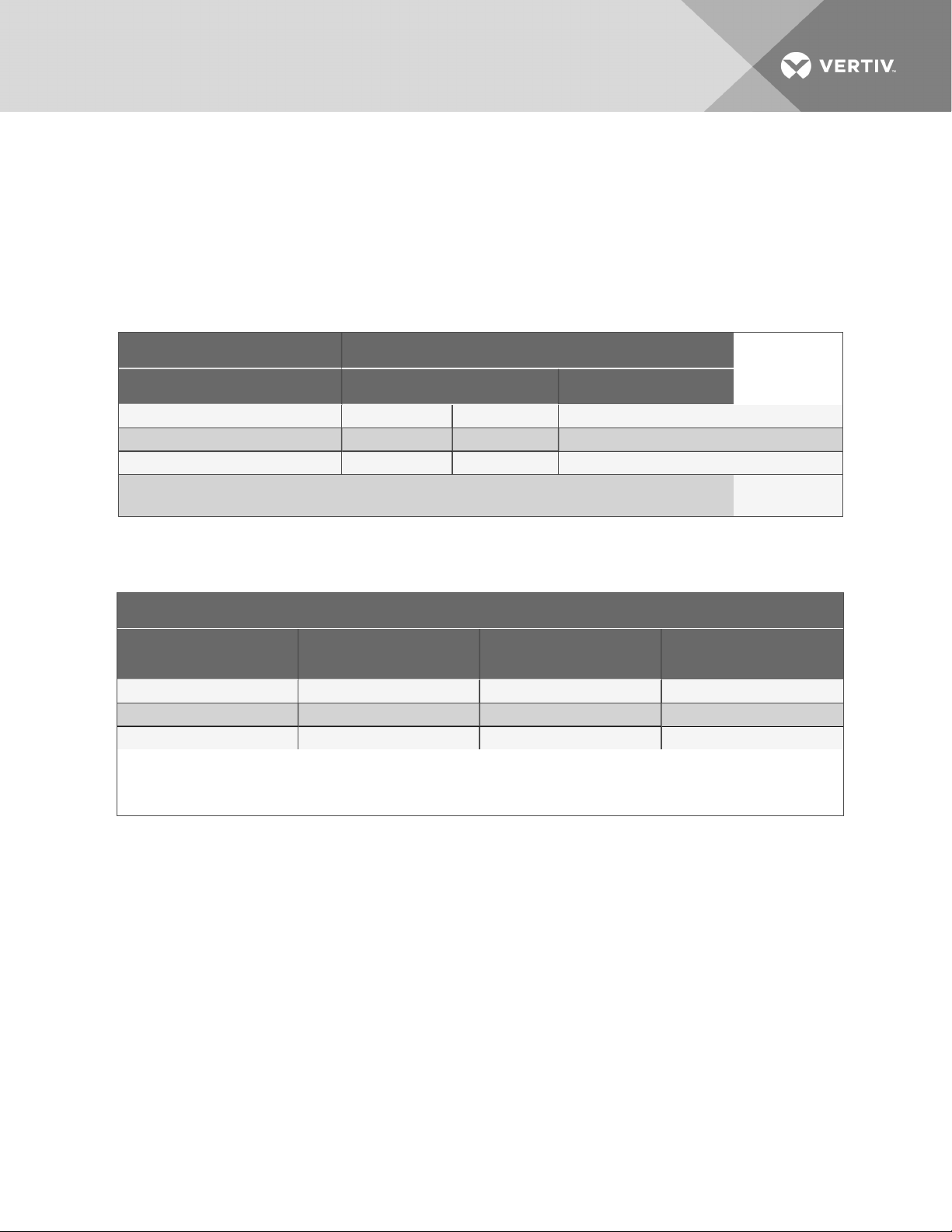
9.14 Drycooler Aquastat Settings
Applications with the Optional Stat Setting require field piping to be insulated to prevent condensation.
Table 9.7 below, shows acceptable applications where stats must be adjusted to Optional Setting.
Aquastats must be field-adjusted to Optional Setting for:
• GLYCOOL/Dual Cool applications
• Single Drycooler loops with motor ball valve flow controls.
Table 9.7 Water/glycol system conditions requiringoptionalsettingsforaquastats
Flow C ontrol: MBV
Cooling Type: Glycol GLYCOOL™
Drycoolers inLoop 1 Multiple 1 Multiple
Stat Setting* Optional Factory Optional Optional
Insulate FieldPiping Yes No Yes Yes
* See Table 9.8 below
MBV = motorized ball valve
Table 9.8 Aquastat settings—2-fan through 4-fan drycoolers
Dial Setting (Stat OpenTemp) Set for Mid Differential8°F (4.4°C) Rise to Close
Aquastat # Fans
AQ1 F1 65°F (18.3°C) 35°F (1.7°C)
AQ2 F2 & F3 75°F (23.9°C) 45°F (7.2°C)
AQ3 F4 70°F (21.1°C) 40°F (4.4°C)
1. All drycoolers are shipped at Factory Setting.
2. Factory S etting is used for all glycol applications, except single drycooler loops with motor ball valve controls.
3. Stats must be field-adjustedto Optional Setting for GLYCOOL/Dual Cool applications andall single drycooler loops using motor ball
valve flow controls.
Factory Setting (Glycol)
(see Notes1 and2)
Optional Sett ing (GLYCOOL)
(see Note 3)
Vertiv | Liebert® PDX™ and PCW™Installer/User Guide | 89
Page 90

This page intentionally left blank.
Vertiv | Liebert® PDX™ and PCW™Installer/User Guide | 90
Page 91

10 PREVENTIVE MAINTENANCE CHECKLIST
Source: DPN002952, Rev. 2
Inspection Date Job Name
Indoor Unit Model # Indoor Unit Serial Number #
Condenser/Drycooler Model # Condenser/Drycooler Serial #
Room Temperature/Humidity °% Ambient Temperature °
Not all units will have all components. To determine your unit’s configuration, compare the Indoor Unit
Model # above above and the information in the Components and Nomenclature section.
Good maintenance practices are essential to minimizing operation cost and maximizing product life. Read
and follow all applicable maintenance checks listed below. At a minimum, these checks should be
performed semi-annually. However, maintenance intervals may need to be more frequent based on sitespecific conditions. Review the unit user manual for further information on unit operation. We recommend
the use of trained and authorized service personnel, extended service contracts, and factory-certified
replacement parts. Contact your local sales representative for more details.
Check all that apply:
Evaporator/Filters
1. Check/Replace filters
2. Grille area unrestricted
3. Wipe section clean
4. Coil clean
5. Clean condensate pan
6. Clean trap in condensate drain
7. Check/Test filter-clog switch operation (if equipped)
Blower Section (EC fan)
1. Mounting bolts tight
2. Fan-guard bolts tight
3. Impeller spins freely
4. Check/Test air sail switch (if equipped)
5. Motor amp draw
• Compare to nameplate amps
#1 L1 L2 L3
#2 L1 L2 L3
#3 L1 L2 L3
Reheat
1. Inspect elements
2. Check wire connections (inside reheat box)
3. Reheat amp draw
L1 L2 L3
Vertiv | Liebert® PDX™ and PCW™Installer/User Guide | 91
Page 92

Steam Generating Humidifier (if equipped)
1. Check drain valve/drain lines/trap for damage/clogs/leaks
2. Check water fill valve and all supply lines/connection for leaks
3. Check condition of steam hose
4. Clean strainer
5. Replace humidifier bottle if necessary
6. Check operation of humidifier
7. Humidifier amp draw
L1 L2 L3
Infrared Humidifier (if equipped)
1. Check drain lines and trap for damage/clogs/leaks
2. Check/Clean pan for mineral deposits
3. Clean reflector
4. Check water make-up valve/supply lines/connections for leaks
5. Check humidifier lamps (replace if burnt out)
6. Check/Re-torque wire connections (inside humidifier box)
7. Check humidifier high-water alarm operation
8. Humidifier amp draw
L1 L2 L3
Condensate Pump (if equipped)
1. Check for debris in sump
2. Check operation of float(s) (free movement)
3. Check/Clean discharge check valve
Electrical Panel
1. Check fuses
2. Check contactors for pitting (Replace if pitted)
3. Check/Re-torque wire connections
Controls
1. Check/Verify control operation (Sequence)
2. Check/Test changeover device(s) (if equipped)
3. Check/Test water-detection device(s) (if equipped)
4. Check/Test CAN connection between indoor and outdoor units (if equipped)
Refrigeration Piping
1. Check refrigerant lines (clamps secure/no rubbing/no leaks)
2. Check for moisture (sight glass)
3. Check for restriction temperature drop across filter drier
Vertiv | Liebert® PDX™ and PCW™Installer/User Guide | 92
Page 93

Compressor Section (if equipped)
1. Check oil level
2. Check for oil leaks
3. Check compressor mounts (springs/bushings)
4. Cap tubes (not rubbing)
5. Check/Re-torque wire connections (inside compressor box)
6. Compressor operation (vibration/noise)
7. Check crank-case heater fuses/operation (if equipped)
8. Check for refrigerant leaks
9. Suction pressure Circuit #1
10. Discharge Pressure Circuit #1
11. Superheat Circuit #1
12. Low-pressure switch cut out Circuit #1
13. Low pressure cut in Circuit #1
14. High pressure cut out Circuit #1
15. Amp draw
Circuit #1 L1 L2 L3
Water-cooled Condensers (if equipped)
1. Verify proper water maintenance/treatment is being performed
2. Check water-regulating valve (motorized ball valve) operation
3. Verify water flow
4. Clean screen on Y strainer (if equipped)
5. Cap tubes (not rubbing)
6. Check condenser and supply/return lines/connections for water/glycol leaks
7. Entering water temperature ________°
8. Leaving water temperature ________°
Chilled Water/Econ-O-Coil (if equipped)
1. Verify proper water maintenance is being performed
2. Check coil and supply/return lines/connections for water/glycol leaks
3. Stroke free-cooling valve open and closed
Vertiv | Liebert® PDX™ and PCW™Installer/User Guide | 93
Page 94

Liebert MC Condenser (if equipped)
1. Coil clean
2. Fans free of debris
3. Fans securely mounted
4. Motor bearings in good condition
5. Check all refrigerant lines for vibration isolation. Support as necessary
6. Check for refrigerant leaks
7. Check surge-protection device (if installed) status-indicator lights
8. Check/Re-torque wire connections
9. Check contactors for pitting (replace if pitted)
10. Verify operation sequence/set points
11. Charge verification:
a. Outdoor Ambient Temperature__________
b. Subcooling__________
c. Indoor-unit Return-air Temperature__________
d. Sight-glass level (if Lee-Temp or pumped refrigerant)_________
12. Motor amp draw
#1 L1 L2 L3
#2 L1 L2 L3
#3 L1 L2 L3
#4 L1 L2 L3
Drycooler (if equipped)
1. Coil clean free of debris
2. Motor mounts tight
3. Bearings in good condition (motor)
4. Piping support/clamps secure
5. Check/Re-torque wire connections
6. Check contactors for pitting (replace if pitted)
7. Check fuses
8. Verify fan operation
9. Check surge-protection device status-indicator lights (if equipped)
10. Stat Settings ________________________
11. Refrigerant level (Lee-Temp™)
12. Glycol level
13. Glycol solution ----__________________%
14. Water/Glycol solution flowing continuously/clean and free of debris
Vertiv | Liebert® PDX™ and PCW™Installer/User Guide | 94
Page 95

15. Water-treatment plan established and followed for open cooling-tower application
16. Check refrigerant/glycol lines for signs of leaks/repair as found
17. Motor amp draw
#1 L1 L2 L3
#2 L1 L2 L3
#3 L1 L2 L3
#4 L1 L2 L3
Glycol Pump (if equipped)
1. Check pump rotation
2. Check pump and supply/return lines/connections for leaks
3. Pump pressures
#1 Suction Discharge
#2 Suction Discharge
#3 Suction Discharge
4. Amp Draw
#1 L1 L2 L3
#2 L1 L2 L3
#3 L1 L2 L3
5. Verify pump changeover (if multiple pumps)
Vertiv | Liebert® PDX™ and PCW™Installer/User Guide | 95
Page 96
MAINTENANCE NOTES
Name
Signature
Company
Make photocopies for your records. Compare readings/information to previous maintenance worksheet.
To locate your local Vertiv™ representative for Vertiv™-engineered parts, check
https://www.vertivco.com/en-us/support/ or Call 1-800-543-2778.
Vertiv | Liebert® PDX™ and PCW™Installer/User Guide | 96
Page 97

APPENDICES
Appendix A: Technical Support and Contacts
A.1 Technical Support/Service in the United States
Vertiv Services, Inc.
24x7 dispatch of technicians for all products.
1-800-543-2378
Liebert Thermal Management Products
1-800-543-2778
Liebert Channel Products
1-800-222-5877
Liebert AC and DC Power Products
1-800-543-2378
A.2 Locations
United States
Vertiv Headquarters
1050 Dearborn Drive
Columbus, OH, 43085, USA
Europe
Via Leonardo Da Vinci 8 Zona Industriale Tognana
35028 Piove Di Sacco (PD) Italy
+39 049 9719 111
Fax: +39 049 5841 257
Asia
7/F, Dah Sing Financial Centre
3108 Gloucester Road, Wanchai
Hong Kong 852 2572220
Fax: 852 28029250
Vertiv | Liebert® PDX™ and PCW™Installer/User Guide | 97
Page 98

This page intentionally left blank.
Vertiv | Liebert® PDX™ and PCW™Installer/User Guide | 98
Page 99
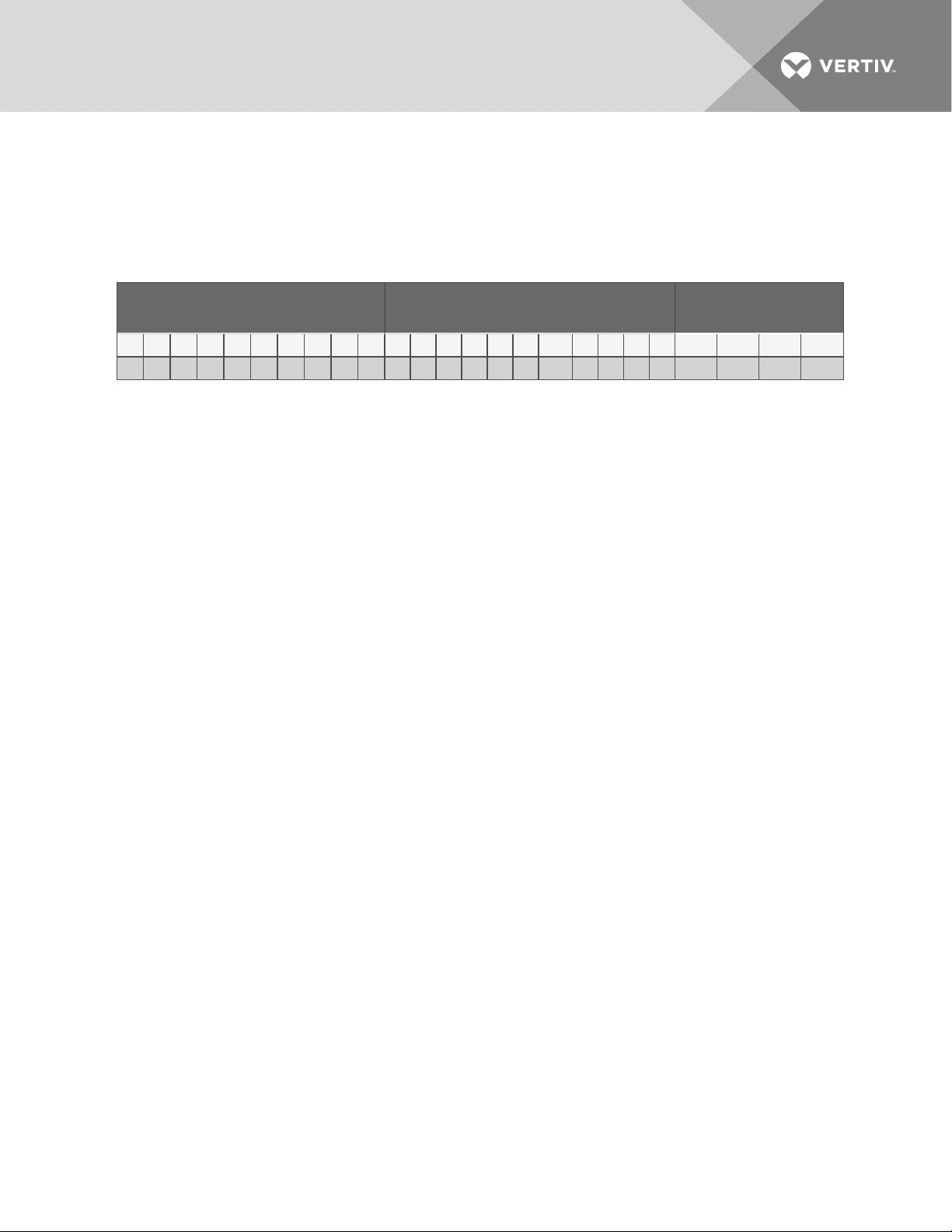
Appendix B: Liebert PDX Model-number Detail
Table B.2 on the next page describes each digit of the 25-digitconfigurationnumber. The 14-digit model
number consists of the first 10 digits and last 4 digits of the configuration number.
Table B.1 PDX 25-digit Configuration Number
Model Number Digi ts 1 to 10 Model Details
1 2 3 4 5 6 7 8 9 10 11 12 13 14 15 16 17 18 19 20 21 22 23 24 25
P X 0 2 9 D A 1 A D H H 2 8 0 1 P L U F P A # # #
ModelNumber Dig its
11 to14
Vertiv | Liebert® PDX™ and PCW™Installer/User Guide | 99
Page 100
Table B.2 PDX Model-number Digit Definitions
Digit Descripti on
Digits 1 and2 = Unit Family
PX = Liebert PDX ( DX)
Digit3, 4, 5= Nominal Cooling Capacity, kW
011
018
023
029
Digit6 = Air Direction and Discharge
D = Downflow for r aised floor
H = Downflow for solid floor - front
1 = Downflow for s olidfloor - front+ right side
2 = Downflow for solid floor - fr ont + left+ rightside
3 = Downflow for solid floor - fr ont + lefts ide
U = Upflow w/ Front Air Return
C = Upflow w/ Bottom Air Return
Digit7 = System Type
A = A ir-Cooled
W = Water/Glycol-Cooled
G = GLYCOOL™
D = Dual Cool (Air- Cooled+ Econ-O-Coilw/3-way MBV)
H = Dual Cool (Water/Glycol-Cooled + Econ-O- Coilw/3-wayMBV)
2 = Dual Cool (Air- Cooled + Econ-O- Coilw/2-way MBV)
3 = Dual Cool (Water/Glycol-Cooled+ Econ-O- Coilw/2-way MBV)
Digit8 = Fan Type
1 = EC plug fans (Variable speed)
Digit9 = Power Supply
A = 4 60V - 3ph - 60Hz
B = 575V - 3ph - 60Hz
C = 208V - 3ph- 60Hz
D = 230V - 3ph - 60Hz
2 = 380 - 3ph - 60Hz
Digit10 = Compress or & Valve (R-410A)
D = Digital Scroll w/TXV
8 = Digital S croll w/ Sound Jacket & TXV
P = Digital Scr oll w/ EEV
9 = Digital Scroll w/ S oundJacket & EEV
S = S croll w/TXV
Digit11 = Humidifier
0 = No humidifier
H = Infrared Humidifier
S = S team Gen Canister Humidifier
Digit12 = Display
H = 9-inch color touchscreen Liebert iCOM™ Display
Digit13 = Reheat
0 = No reheat
2 = Electric reheat (2-Stage)
5 = SCR reheat (PX011 w/ digital scroll and S ystem TypeA or Wonly)
Vertiv | Liebert® PDX™ and PCW™Installer/User Guide | 100
 Loading...