

Page 1

Liebert® PEX3
TM
DX Series
User Manual
Precision Air Conditioning
Page 2

Copyright by Vertiv Co. Ltd.
The content in this document is subject to change without notice. All rights, including rights of translation,
reproduced by printing, copying or similar methods, and even of parts, are reserved. Violators will be liable for
damages. All rights, including rights deriving from patent license or registration of a utility model or design,
are reserved. No part of this document may be reproduced or transmitted in any form or by any means
without the prior written consent of Vertiv Co. Ltd.
Notice
The purchased products, services, and features are stipulated by the contract made between Vertiv Co.,
and the customer. All or part of the products, services, and features described in this document may not be
within the purchasing scope or the usage scope. Unless otherwise specied in the contract, all statements,
information, and recommendations in this document are provided “AS IS” without warranties, guarantees or
representations of any kind, either express or implied. The information in this document is subject to change
without notice. Every eort has been made in the preparation of this document to ensure the accuracy of
the contents, but all statements, information, and recommendations in this document do not constitute a
warranty of any kind, express or implied.
Vertiv Co., Ltd.
China
Homepage: www.vertiv.com
E-mail: [email protected]
Customer service hotline: 4008876510
Asia Pacic
Homepage: www.vertiv.com.
E-mail: [email protected]
Australia
Customer service hotline: 1300367686
New-Zealand
Customer service hotline: 0800100877
For Technical Support, users may contact the nearest Vertiv Co. local sales oice or service centre.
Page 3
Purpose of the Document
This document applies to the series of precision air conditioners and cooling solutions which maintain optimal
environmental control of technological ecosystems at minimal operating costs. This document gives an
overview of the specications, installation, commissioning, and maintenance procedures with troubleshooting
from the user perspective. The gures used in this document are for reference only.
Please read this manual carefully before installing, maintaining, and troubleshooting.
Liebert PEX3 DX series precision CRAC is a professional device, only professionals are permitted to access the
unit and is kept in a place where access is restricted to common people.
Styling used in this Guide
The styles used in the manual will be dened as mentioned in the following table:
Situation Description
Warning/Danger/Caution • The Warning/Danger/Caution note indicates a hazardous or potentially
harmful situation that can result in death or injury. It also indicates
instructions that need to be adhered to, failing which may result in
danger and safety issues thereby having an adverse eect on the
reliability of the device and security. Even for practices not related to
physical injury, to avoid equipment damage, performance degradation,
or interruption in service, follow the warning instruction.
Note
• The Note section indicates additional and useful information. It also calls
attention to best practices and industry-best protocols that are
standardized and help make maximum utilization of the resources at
hand. Helpful information related to the product also comes under the
Note heading, helping the users with the denitions, concepts, and
terminologies used in the manual.
Version History
Version Revision Date Issue Changes
1.0 25.08.2019
---
Page 4

Safety Precautions and Measures
The important safety precautions and measures that should be followed during the installation and
maintenance are described in the following sections.
Read the manual prior to installation and operation of the unit. Only qualied personnel should move, install,
or service this equipment.
Before working on the equipment, the user reads and considers all precautions, compliance and safety
measures. The unit control must be used exclusively for the purpose which it is intended for; the
manufacturer takes no liability for incorrect use or a modication to the unit control.
Adhere to all the Warnings and Cautionary measures included in the manual.
Please read this manual carefully before installing, maintaining and troubleshooting; especially the
Warning/Danger/Caution information in the User Guide. Apart from the User Guide, also pay attention
to the warning labels on the unit and its components.
This manual is retained for the entire service life of the unit. The user must read all the precautions, danger,
warnings, and cautionary measures mentioned in the manual prior to carrying out any operations on the unit.
Each unit is equipped with an electric insulation which allows the users to work in safe conditions. The main
switch is positioned on the electrical panel cover; to access it, open the right door. Before any maintenance
operation, switch o the unit with this electrical insulation device to eliminate risks such as electrical shocks,
burns, automatic restarting, moving parts, and remote control. The panel key, supplied along with the unit,
must be kept by the personnel responsible for the maintenance. The protective covers can be removed after
the electric power has been cut o by opening the main switch.
In the following sections, notice the various cautionary measures and warnings that need to be read carefully
prior to installing or operating the system.
Disconnect the local and remote power supplies prior to working with the unit.
Prior to the installation process, read all the instructions, verify if all the parts are in place, and check the
nameplate to ensure the voltage matches the available utility power for the unit.
The controller doesn’t isolate power from the unit even in the O mode, and some internal components still
require and receive power during the O mode.
If the unit door is open while the fans are operating, the airow may result in abrupt slamming of the door
resulting in injury. Another aspect is the presence of small objects in the fans bay that can result in object
ejection during the fan start-up and there is a probable risk of being hit by these objects resulting in grievous
injury and causing equipment damage.
The unit contains uids and gases under high pressure. Therefore, the pressure should be relieved before
working with the piping.
Page 5

Various components such as compressors, refrigerant discharge lines, and humidiers are extremely hot during
the unit operation. Therefore, allow suicient time for the unit to cool down before working with the unit cabinet.
Handle the unit with extreme caution and wear safety equipment such as protective gloves, safety shoes, and
arm protection while working with the hot compressors, discharge lines, and reheats.
There is a risk of water leaking that can damage both the equipment and the building. Eective water drain
connection and facilities should be available. Installation should be precise. Implementation of the application
and service practices should be appropriate and fault-free. Failure to comply with these norms will result in
water leakage from the unit. Water leakage can lead to massive damage and loss of critical equipment in the
hosting ecosystem. Therefore, care should be taken to ensure that the unit is not located directly above any
equipment that could sustain damage due to water and excessive moisture. Use of a leak detection system for
the unit and system supply lines are recommended by Vertiv Co.
Page 6

Vertiv | Liebert® PEX3™ Series Precision Air Conditioner | User Manual i
Table of Contents
Table of Contents
Chapter 1: Product Overview................................................................................................................................................................................1
1.1. Product Introduction ................................................................................................................................................................................................ 1
1.2. Model Description .................................................................................................................................................................................................... 2
1.3. Model Nomenclature ..............................................................................................................................................................................................3
1.4. Components of PEX3 Model ..........................................................................................................................................................................4
1.4.1. Indoor Unit Parts ........................................................................................................................................................................................... 5
1.4.2. 9-Inch Color Display ..................................................................................................................................................................................7
1.4.3. Condenser .......................................................................................................................................................................................................... 8
1.4.4. Remote Monitoring Software .......................................................................................................................................................... 8
1.5. Optional Components ...........................................................................................................................................................................................8
1.5.1. Electrode Humidier ................................................................................................................................................................................. 8
1.5.2. 2-stage Electrical Heating .................................................................................................................................................................. 8
1.5.3. Dual Power Supply- ATS ...................................................................................................................................................................... 8
1.5.4. Dual Power Supply- Parallel .............................................................................................................................................................. 8
1.5.5. Plenum Conguration ............................................................................................................................................................................. 9
1.5.6. Dual Power (Interlocked Contactors) ...................................................................................................................................... 9
1.5.7. Large & Small Display ..............................................................................................................................................................................9
1.5.8. IS-UNITY-DP Card Assembly .......................................................................................................................................................... 9
1.5.9. Smoke Detectors .......................................................................................................................................................................................10
1.5.10. Fire Detectors .............................................................................................................................................................................................10
1.5.11. Supply Air Pressure Sensor ............................................................................................................................................................10
1.5.12. Supply Air Temperature Sensor ...............................................................................................................................................10
1.6. Refrigerant Requirement .................................................................................................................................................................................10
1.6.1. Charging Refrigerant ................................................................................................................................................................................11
1.7. Storage & Operating Environment Requirements ...................................................................................................................12
Page 7

Vertiv | Liebert® PEX3™ Series Precision Air Conditioner | User Manual ii
Table of Contents
Chapter 2: Installation................................................................................................................................................................................................13
2.1. Pre-installation ...........................................................................................................................................................................................................13
2.1.1. Transportation & Movement ............................................................................................................................................................13
2.1.2. Unpacking ........................................................................................................................................................................................................14
2.1.3. Inspection ..........................................................................................................................................................................................................16
2.2. Installation Preparation (Site Preparation) ................................................................................................................................... 16
2.2.1. Equipment Room Requirements ................................................................................................................................................ 16
2.2.2. Installation Space Requirements .............................................................................................................................................. 17
2.2.3. Maintenance Space Requirement ...........................................................................................................................................18
2.2.4. Installation Tools ......................................................................................................................................................................................20
2.2.5. System Arrangement during Installation .......................................................................................................................... 21
2.2.6. System Installation Mode ................................................................................................................................................................24
2.3. Mechanical Installation ....................................................................................................................................................................................27
2.3.1. Indoor Unit Size and Weight (Product Dimension) ................................................................................................. 27
2.3.2. Plenum Dimensions (for Upow Unit) ................................................................................................................................ 29
2.3.3. Dimension and Weight of Condenser ..................................................................................................................................29
2.3.4. Base Plate Cut-out Position and Dimension ................................................................................................................29
2.3.5. Position and Dimension of Air Outlet on Top Cover ............................................................................................. 35
2.3.6. Indoor Installation ...................................................................................................................................................................................36
2.3.7. Installing Floor Stand ............................................................................................................................................................................38
2.3.8. Installation of Indoor Unit ................................................................................................................................................................38
2.3.9. Pipe Installation Unit (Air-cooled Units) ........................................................................................................................... 39
2.3.10. Infrared Humidication Inlet Pipe Connection ........................................................................................................ 40
2.3.11. Connection of Copper Pipe (Discharge and Liquid pipe) between
Indoor and Outdoor Unit .................................................................................................................................................................41
2.3.12. Height Dierence Requirements and Equivalent Length Calculation .............................................. 43
2.3.13. Pipe Installation Unit (Water-cooled unit) ....................................................................................................................44
Page 8

Vertiv | Liebert® PEX3™ Series Precision Air Conditioner | User Manual iii
Table of Contents
2.3.14. Connection between Water inlet and Outlet Pipe of Cooling Water ..................................................44
2.3.15. Lowering the Fan ...................................................................................................................................................................................46
2.3.16. Removing Transportation Fixing Plate of the Compressor .......................................................................... 49
2.3.17. Removing of Fasteners of Infrared Humidier ..........................................................................................................49
2.3.18. Removing Pipe Fasteners .............................................................................................................................................................50
2.3.19. Installation Inspection .......................................................................................................................................................................50
2.4. Electrical Installation ...........................................................................................................................................................................................51
2.4.1. Installation Precautions .......................................................................................................................................................................51
2.4.2. Wiring of Indoor Unit ............................................................................................................................................................................ 51
2.4.3. Connecting Control Cables ........................................................................................................................................................... 55
2.4.4. Connecting Water-Under-Floor Sensor ............................................................................................................................ 56
2.4.5. Remote Shutdown Control Line Connection ...............................................................................................................56
2.4.6. Customized Alarm Terminal .........................................................................................................................................................56
2.4.7. External General Alarm ...................................................................................................................................................................... 56
2.4.8. Condenser Wiring ................................................................................................................................................................................... 57
2.4.9. Check the Installation .........................................................................................................................................................................58
Chapter 3: Touchscreen Operation ........................................................................................................................................................... 59
3.1. Touchscreen Display and User Interface ....................................................................................................................................... 59
3.2. Touchscreen Status Dial ................................................................................................................................................................................ 61
3.2.1. Dial Background-Color Status Indication ..........................................................................................................................61
3.3. Control Header ........................................................................................................................................................................................................63
3.3.1. Powering-On iCOM and Logging-in/ Unlocking Controls ................................................................................63
3.3.2. Powering-on the Thermal Management Unit .............................................................................................................63
3.3.3. Powering-O the Thermal Management Unit.............................................................................................................65
3.3.4. Logging Out ..................................................................................................................................................................................................65
3.3.5. Setting the Date and Time .............................................................................................................................................................66
Page 9

Vertiv | Liebert® PEX3™ Series Precision Air Conditioner | User Manual iv
Table of Contents
3.3.6. Searching .........................................................................................................................................................................................................66
3.3.7. Using Context-Sensitive Help .....................................................................................................................................................67
3.3.8. About iCOM Version .............................................................................................................................................................................67
3.3.9. Accessing the User and Service Functions ................................................................................................................... 67
3.3.10. User Menu .................................................................................................................................................................................................... 67
3.3.11. Service Menu ..............................................................................................................................................................................................68
3.3.12. Advanced Menu ......................................................................................................................................................................................69
3.4. User Operation ........................................................................................................................................................................................................ 70
3.4.1. Editing Humidity Setpoints ............................................................................................................................................................70
3.4.2. Editing Temperature Setpoints .................................................................................................................................................70
3.4.3. Viewing Unit Alarms .............................................................................................................................................................................. 71
3.4.4. Silencing an Audible Alarm ............................................................................................................................................................ 71
3.4.5. Acknowledging Alarms ....................................................................................................................................................................... 71
3.4.6. Viewing the Event Log ....................................................................................................................................................................... 72
3.4.7. Viewing Sensor Data ............................................................................................................................................................................ 73
3.4.8. Managing Run Hours for a Component ............................................................................................................................ 73
3.4.9. Setting Run Hours to Zero ............................................................................................................................................................. 73
3.4.10. Viewing Teamwork, Stand-by, Cascade and Operating Status ............................................................... 74
Chapter 4: iCOM Controller Operation .................................................................................................................................................75
4.1. LCD Screen ...................................................................................................................................................................................................................75
4.2. Button and Indicator Panel .......................................................................................................................................................................... 75
4.3. Structure Chart of Control Menu ...........................................................................................................................................................77
4.4. Start-Up Interface .................................................................................................................................................................................................78
4.5. Main Interface ...........................................................................................................................................................................................................78
4.6. User Menus .................................................................................................................................................................................................................79
4.7. Password ....................................................................................................................................................................................................................... 80
Page 10

Vertiv | Liebert® PEX3™ Series Precision Air Conditioner | User Manual v
Table of Contents
4.8. Setpoints .......................................................................................................................................................................................................................80
4.9. Event Log ...................................................................................................................................................................................................................... 81
4.10. Graphics ....................................................................................................................................................................................................................... 81
4.11. Set Alarms ................................................................................................................................................................................................................... 82
4.12. Display Setup ......................................................................................................................................................................................................... 83
4.13. Total Run Hrs .........................................................................................................................................................................................................84
4.14. Sleep Mode .............................................................................................................................................................................................................. 86
4.15. Service Info ............................................................................................................................................................................................................... 86
4.16. Active Alarms ......................................................................................................................................................................................................... 86
Chapter 5: Application of INTELLI SLOT ........................................................................................................................................... 87
5.1. Introduction of Host Communication Card ...................................................................................................................................87
5.2. Commissioning Host Communication Component ............................................................................................................ 88
5.2.1. Assigning the Card’s IP Address ............................................................................................................................................... 88
5.2.2. Connect an Ethernet Cable ..........................................................................................................................................................89
5.2.3. Connect a RS-485 Serial Cable ................................................................................................................................................ 90
Chapter 6: System Operation and Maintenance ........................................................................................................................ 91
6.1. Routine Maintenance Inspection Items (Monthly) ................................................................................................................ 91
6.2. Routine Maintenance Inspection Items (Semi-Annual) ................................................................................................. 92
6.3. Self-Diagnostic System .................................................................................................................................................................................. 93
6.4. Check the Electrical Connections and Maintenance ....................................................................................................... 93
6.5. Appearance Inspection and Maintenance of Controller Components ............................................................94
6.6. Air-Cooled Condenser Maintenance Guide ............................................................................................................................... 95
6.7. Water-Cooled Condenser Maintenance Guide ........................................................................................................................ 95
6.8. Filter Maintenance Guide .............................................................................................................................................................................96
6.9. Infrared Humidier Maintenance Guide ..........................................................................................................................................97
Page 11

Vertiv | Liebert® PEX3™ Series Precision Air Conditioner | User Manual vi
Table of Contents
6.10. Electric Heater Maintenance Guide .................................................................................................................................................97
Chapter 7: Diagnosis and Maintenance ...............................................................................................................................................99
7.1. Fault Diagnosis and Treatment of Fans ........................................................................................................................................... 99
7.2. Fault Diagnosis and Treatment of Infrared Humidier..................................................................................................100
7.2.1. Infrared Humidier Troubleshooting ..................................................................................................................................100
7.2.2. High-Temp Switch ................................................................................................................................................................................ 101
7.3. Compressor and Refrigeration System - Fault Diagnosis and Treatment ...................................................101
7.4. Heating System - Fault Diagnosis and Treatment ............................................................................................................. 105
Appendix I: Wiring Diagram Infrared Humidier (for Air-cooled) .......................................................................... 106
Appendix II: Wiring Diagram Infrared Humidier (for Water-cooled) ................................................................ 107
Appendix III: Circuit Diagram Dual Power .........................................................................................................................................108
Appendix IV: Menu Structure of iCOM Controller (Users Menus) ......................................................................... 109
Appendix V: Table Names and Content of Harmful
Substances in Products ........................................................................................................................................................................................110
Appendix VI: Routine Maintenance Inspection Items
(Monthly) ............................................................................................................................................................................................................................... 111
Appendix VII: Routine Maintenance Inspection Items
(Semi-Annual) ................................................................................................................................................................................................................... 112
Page 12

Vertiv | Liebert® PEX3™ Series Precision Air Conditioner | User Manual 1
Product Overview
Chapter 1: Product Overview
1.1. Product Introduction
The ‘Liebert PEX3 series’ is the next generation series of air conditioners that provide precise environmental
control. The Liebert PEX3 models are the latest enterprise-grade products from the Liebert family.
Incorporating the high standards associated with the Liebert name, the PEX3 series utilizes the latest
technology, system components, and streamlined manufacturing process.
Liebert PEX3 air conditioner are specically created and designed for data centers, equipment room, computer
rooms, and similar ecosystems that require high control accuracy in terms of inside environment condition. It
caters to sensitive applications that require a suitable environment for optimal performance. Therefore, care
should be taken while testing these sensitive products or maintaining a favorable environment for mission
critical equipment, as even a slight deviation may lead to inaccurate results. Precision Air Conditioning must not
only keep room conditions within a specic range but also be able to react quickly to a drastic change in heat
load and prevent wide temperature uctuations.
The PEX3 unit comes with the features such as high reliability, high sensible heat ratio, and large airow. It is
an excellent system that adheres to the standards of Precision Air Cooling in terms of energy-eiciency, space
requirements, and reliability.
Air-cooled series
The Liebert PEX air-cooled series air conditioner comprises indoor and outdoor units with the standard
conguration of Liebert PEX condenser unit, it can reduce noise pollution to the minimum while meeting
system cooling requirements through the pressure regulating the fan speed.
Water-cooled series
The Liebert PEX water-cooled series air conditioner uses integrated structure and highly eective brazed-plate
heat exchanger (BPHE), thus it is a compact, eicient and quiet in the operating conditions (only P1030 unit).
Page 13
Vertiv | Liebert® PEX3™ Series Precision Air Conditioner | User Manual 2
Product Overview
1.2. Model Description
This chapter introduces the model, appearance, components, optional conguration and refrigerant
requirements of Liebert PEX3. The ‘Liebert PEX3 Series Precision Air Conditioner’ (“PEX3” for short hereafter) is
a cooling equipment, a medium-large sized precision environment control system, adapted to the environment
control of the equipment room or computer room, featuring high reliability, high sensible heat ratio and large
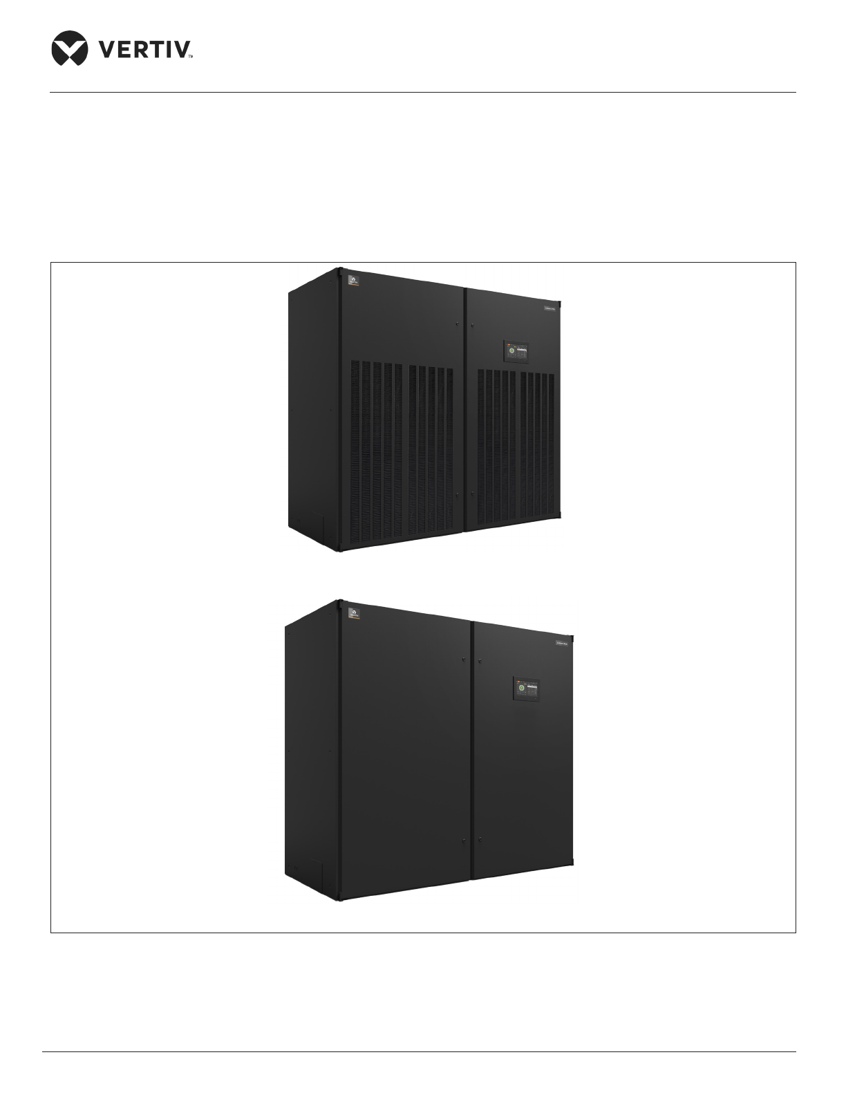
airow. The appearance of Liebert PEX3 models are shown in Figure 1-1.
Upflow Model
Downflow Model
Figure 1-1 Liebert PEX3 Models
Page 14
Vertiv | Liebert® PEX3™ Series Precision Air Conditioner | User Manual 3
Product Overview
1.3. Model Nomenclature
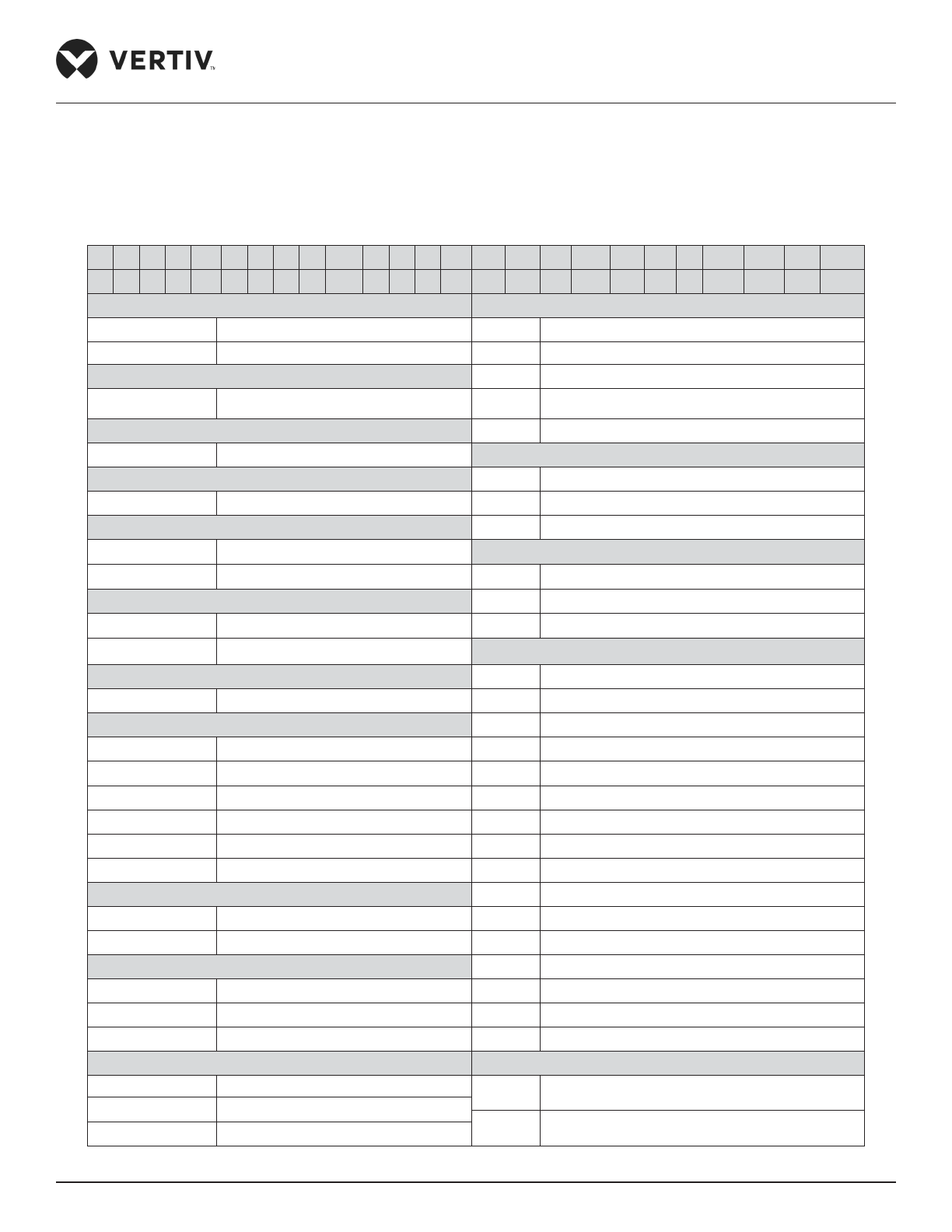
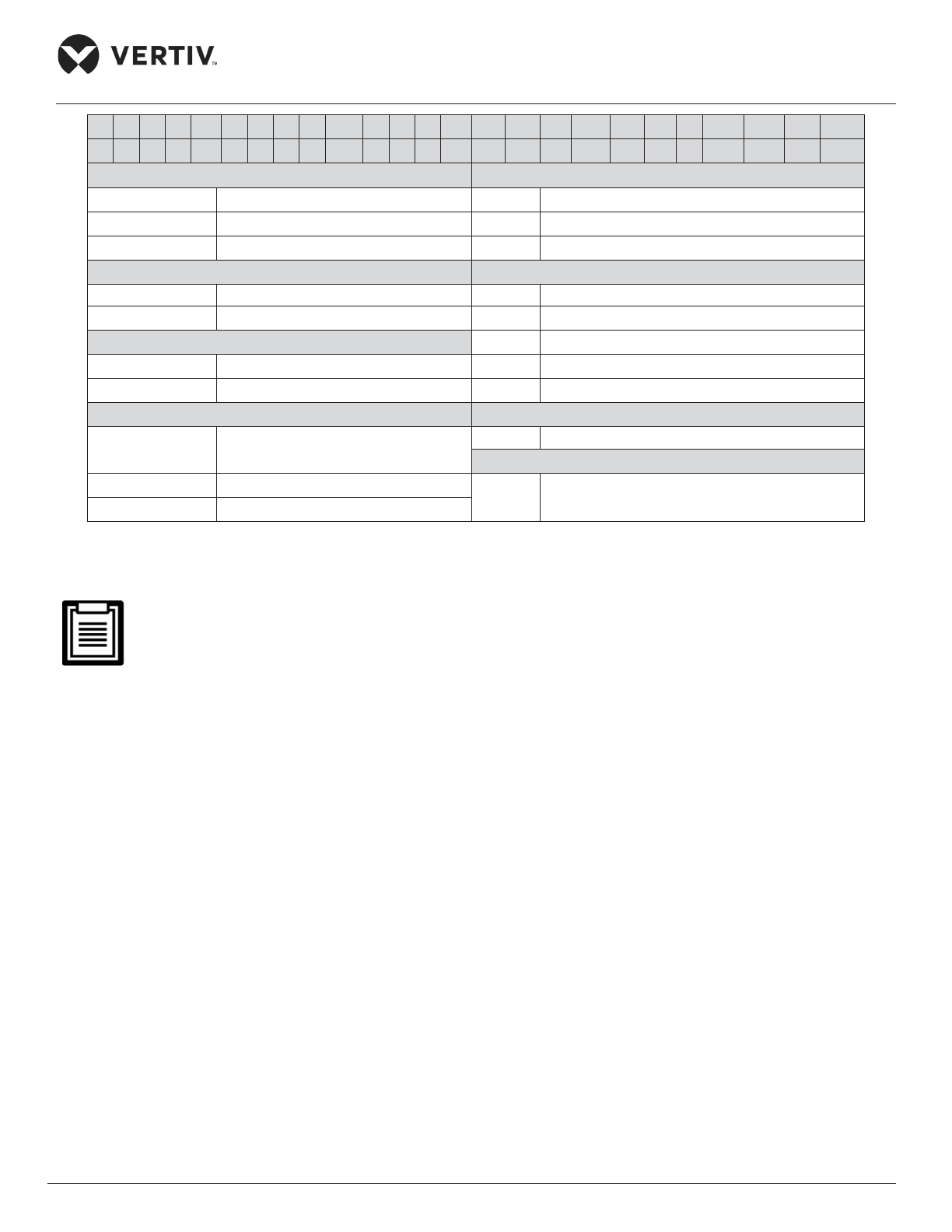
The Liebert PEX3 series model is fully-dened by 25 digits, as represented in Table 1-1.
Table 1-1 Liebert PEX3 Model Nomenclature
1 2 3 4 5 6 7 8 9 10 11 12 13 14 15 16 17 18 19 20 21 22 23 24 25
P 1 0 3 0 D A 1 0 6 H 9 1 2 E 1 D L 0 0 C E 0 3 2
Digit 1,2 Product Model Digit 17 Mains Switch High Voltage Option
P PEX3
0 None
1-2 Number of Modules/ Bays D Main non-Locking Disconnect
Digit 3 Net Cooling Capacity kW P Dual Power Supply Parallel
0-9 Nominal Net Cooling Capacity- kW
A Dual Power Supply Interlocking Contactor
Digit 4 Net Cooling Capacity kW T Dual Power Supply Auto Transfer Switch
0-9 Nominal Net Cooling Capacity- kW
Digit 18 Installation Option
Digit 5 Net Cooling Capacity kW 0 None, Standard Pipe, No Low Ambient Kit
0-9 Nominal Net Cooling Capacity- kW
H Re-heat & Humidity Lockout
Digit 6 Air Discharge
L Air-cooled, Long pipe> 30 m
U Upflow
Digit 19 Monitoring
D Downflow 0 None
Digit 7 System Type 7 Unity Card
A Air Cooled
8 Unity Card*2
W
*
Water Cooled Digit 20 Sensors
Digit 8 Airow
0 None
1 EC Plug Fan
A Supply Air Pressure Sensor
Digit 9 Power Supply S Smoke Sensor
0 400 V/ 3 Ph/ 50 Hz+N
H High Temperature
7 380 / 3 Ph/ 60 Hz+N F Smoke & High Temp
C 208 V/ 3 Ph/ 60 Hz N Supply Air Temperature Sensor
D 230 V/ 3 Ph/ 60 Hz 1 A+S
A 460 V/ 3 Ph/ 60 Hz 2 A+H
8 400 V/ 3 Ph/ 50 Hz 3 A+F
Digit 10 Cooling System 4 N+S
4 Compliant Scroll Dual Circuit, R410A 5 H+N
6 Compliant Scroll Single Circuit, R410A
6 A+N
Digit 11 Humidication 7 H+N+S
0 None 8 A+N+S
H Infrared Humidifier
9 A+H+N
S Electrode Humidier B A+F+N
Digit 12 Display Digit 21 Packaging
9 9-inch HMI Display
P Package- Standard Cardboard and Wooden Pallet
S Small Display
C Packaging– Wooden Crate
L Large Display
Page 15
Vertiv | Liebert® PEX3™ Series Precision Air Conditioner | User Manual 4
Product Overview
1 2 3 4 5 6 7 8 9 10 11 12 13 14 15 16 17 18 19 20 21 22 23 24 25
P 1 0 3 0 D A 1 0 6 H 9 1 2 E 1 D L 0 0 C E 0 3 2
Digit 13 Re-heating Digit 22 Special Requirements
0 None A SFA- None
1 Electrical Heating Std. 1 Stage
P For Export with Condensate Pump
2 Electrical heating Opt. 2 Stage
E For Export
Digit 14 Filtration Digit 23 Order Identier
2 G4 0 Standard ESP
3 F5 1 50 Pa ESP
Digit 15 Coil and Valves 2 100 Pa ESP
E Standard DX Air Cooled Coil, EEV
3 150 Pa ESP
6 Water-cooled, 2-way valve 4 200 Pa ESP
Digit 16 Enclosure Option Digit 24 Order Identier
1
Standard Color Black Orange Peel Grain
Coating
3 Factory Code
Digit 25 Order Identier
2 White orange peel grain coating
2 Factory Code
6 Color charcoal grey w/ double skin
The standard components are represented in ‘Bold Italic’ font in Table 1-1.
*DX Water-cooled version is applicable for 30 kW.
1.4. Components of PEX3 Model
An overview of the main components, optional components and features of the Liebert PEX3 is mentioned in
this section. Liebert PEX3 components include indoor unit, outdoor unit, and remote monitoring software.
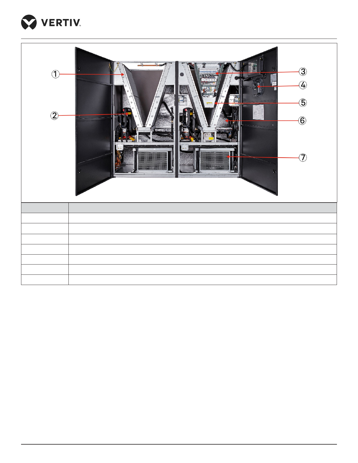
Figure 1-2 shows main components of PEX3 model.
Page 16
Vertiv | Liebert® PEX3™ Series Precision Air Conditioner | User Manual
5
Product Overview
No. Description
1 Evaporator Coil
2 Compressor
3 Electrical Panel
4 HMI Display
5 Filter
6 Electronic Expansion Valve (EEV)
7 EC Fan
Figure 1-2 Main Components of PEX3 Model
1.4.1. Indoor Unit Parts
The PEX3 Air-cooled indoor unit includes Compressor, Evaporator, Electronic Expansion Valve, Infrared
Humidier, EC Fan, Electrical Heating, Sight Glass, Filter Dryer and iCOM Controller. The description of the main
components is tabulated in the Table 1-2. In case of the water-cooled series indoor unit also includes BPHE and
MBV (2-way).
Page 17

Vertiv | Liebert® PEX3™ Series Precision Air Conditioner | User Manual 6
Product Overview
Table 1-2 List of Indoor Unit Components
Component Description
Cabinet
The cabinet frame is constructed from 2.5mm, 2.0mm and 1.2mm folded galvanized steel. The
exterior panels are constructed from 1.2mm zinc coated sheet of steel and insulated with foam
insulation. The cabinet is powder coated in Charcoal Grey color and has a textured nish. The
hinged front doors can be removed, and includes captive 1/4 turn fasteners.
Compressor
Equipped with compliant scroll compressor, it withstands high vibration, and features low noise and
high reliability.
Evaporator
• Uses parallel ow micro-channel evaporator with higher heat transfer eiciency. The material
used for evaporator is Aluminum.
• Detailed design and verication for internal distributor of the evaporator to ensure uniformity of
distribution of the refrigerant, the utilization of the evaporator is considerably improved.
Electronic
Expansion
Valve (EEV)
• The EEV is designed for precision modulating control of the refrigerant mass ow.
• The EEV simultaneously collects temperature and pressure signals to accurately regulate the
refrigerant ow. The EEV’s wide operating envelope also reduces the condensing pressure,
thereby resulting in signicant energy savings.
Infrared
Humidier
• Infrared humidier structure is simple, easy to disassemble, clean and maintain.
• The infrared humidier application reduces the dependence on water quality, it takes a very
short time to start up and reach the humidication requirement, it has the performances like high
humidifying capacity and high eiciency.
EC Fan
• Uses EC fans with PP plastic blade material that enable high eiciency, space-saving, low noise
characteristics.
• The structure of EC fan unit is carefully designed, downow unit adopts a “in-oor” design, this
design can lower the EC fan below the oor to supply air, to further improve the eiciency of air
supply.
Electrical
Heating
Electrical heating features faster heating rate, uniform heating, safety and reliability. The material
used for electrical heating is PTC ceramic heating element and aluminum pipe.
Sight Glass
The windows of the system loop observe the state of the refrigerant, detects the system’s moisture
content. The background color of sight glass changes once the moisture of the system exceeds
permissible limits.
Filter Dryer
It can eectively remove moisture present in the system, while the system is operating for
long-term. To ensure the normal operation of the system removal of impurities is vital.
BPHE (Water
Cooled)
The brazed plate auto-cleansing BPHE is used, where plates are constructed by 316 stainless steel
and brazing material is copper. It features compact structure and high heat exchanging eiciency.
The maximum working pressure for BPHE is 46 bar. Rotalock connections are provided for water
and refrigerant sides.
MBV (Water
Cooled)
The 2-way motorized ball valve is used. The water ow in the BPHE can be regulated through the
intelligent valve position control of the control board, so as to ensure stable system operation, and
the maximum working pressure for MBV is 40 bar.
Page 18
Vertiv | Liebert® PEX3™ Series Precision Air Conditioner | User Manual 7
Product Overview
Component Description
Long Pipe Kit
The long pipe kit can prevent the refrigerant from returning and concentrating after the compressor
is turned o, ensuring normal start of the compressor and making the system safer. The solenoid
valve is installed internally, and the check valve is supplied loose for installation on site.
iCOM
Controller and
HMI Display
• The standard features available in PEX3 unlike legacy PEX series are the highest capability for
unit control, communication, and monitoring of CRAC units.
• Oers the highest capability for unit control, communication, monitoring of CRAC units.
• Speeds setup and installation and simplies control of CRAC units, putting cooling-system
monitoring and management at customers ngertips.
• Uses a rm touch, or consider a stylus when interacting with the touchscreen.
• User and service menus are password-protected to prevent unauthorized changes to cooling
unit operation.
• The touchscreen is back-lit and auto-dims after a period of non-use, the turns o and touch the
screen to re-illuminate the main screen.
• iCOM ships with default settings for eicient and eective operation of most cooling-units and is
easily congured to meet any requirements.
• iCOM menus and displays are based on the options installed on the cooling units that it monitors
and manages.
• LCD screens with dark-gray backlight and 800x480 pixels.
• Display the real-time values of the CRAC’s status, active and history alarms.
• Self-recovery after power failure.
• It can store up to 400 history event records.
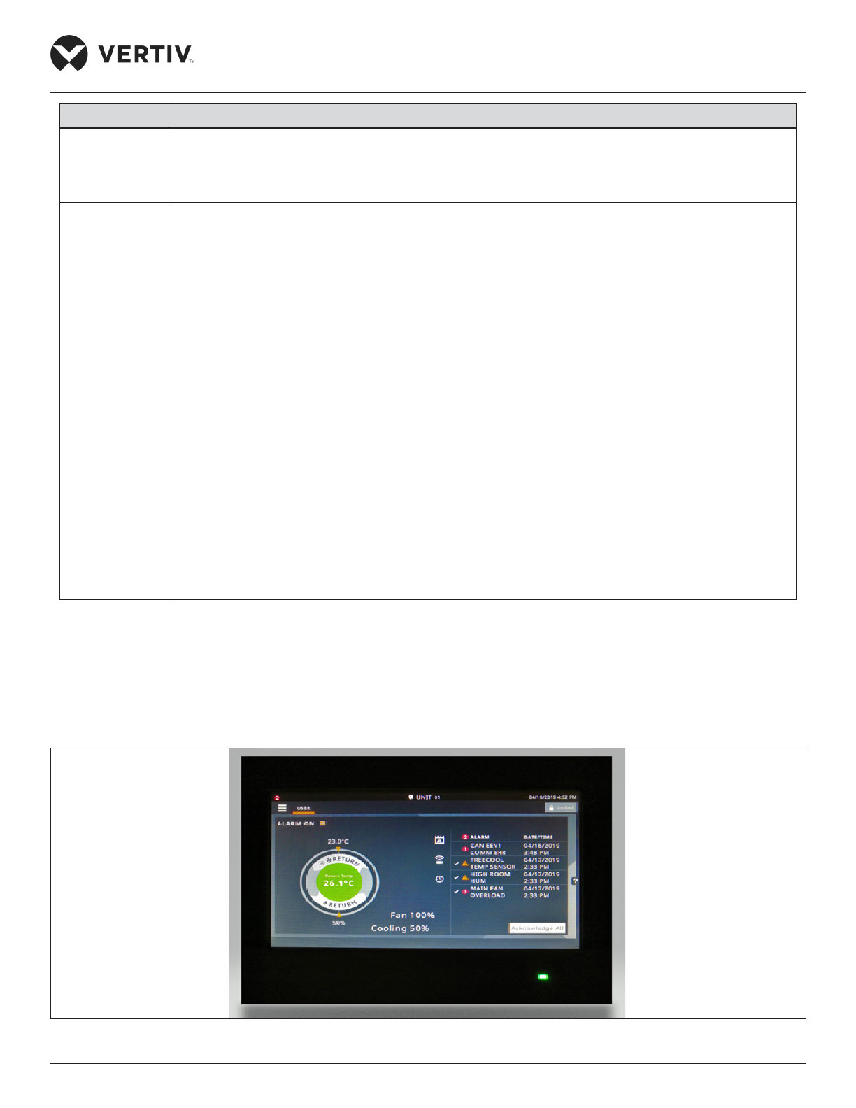
1.4.2. 9-Inch Color Display
PEX3 unit is available with 9-inch touch screen as a standard display, using multi-color 800×480 dot-matrix
liquid crystal touch screen with white backlight as shown in Figure 1-3. The operation of the unit becomes
simpler and more convenient, and the status view of the unit is more visualized.
Figure 1-3 iCOM Controller Display
Page 19

Vertiv | Liebert® PEX3™ Series Precision Air Conditioner | User Manual 8
Product Overview
1.4.3. Condenser
Two types of condensers are available, for details, refer to “Liebert PEX Condenser User Manual” and “LVC
Series Condenser User Manual”.
1.4.4. Remote Monitoring Software
Liebert PEX3 units interface with the BMS system through Modbus/ SNMP/ BACnet communication protocol
by unity card, which enables Liebert PEX3 to communicate with the host computer and receive the control
instructions from the host software. By default one unity card is congured in the unit, but on the request two
unity cards can be congured.
1.5. Optional Components
1.5.1. Electrode Humidier
The electrode humidier uses the electrodes to boil the water in humidier bottle to produce steam for
humidication purpose. It has a specic (soft water) requirements in terms of water quality and sizes of inlet/
outlet pipes as compared to the standard infrared humidier.
1.5.2. 2-stage Electrical Heating
The 2-stage electrical heating can be selected based on the heating requirement. The electrical heating can
be divided into two stages by conguring the controller. The heater starts step-wise according to the heating
requirement. It not only maintains the room temperature but also reduces the energy consumption.
1.5.3. Dual Power Supply- ATS
The dual power ATS can automatically detect both the power sources (source 1 & source 2). In case of
break-down of the preferred power source, ATS is equipped to automatically switch to the source 2. It can also
provide an output signal associated with power alarm.
1.5.4. Dual Power Supply- Parallel
In dual power supply parallel, there are two sources of power- one is connected through UPS to the fan and
the control board. While, the components such as electrical heating and humidier are connected to other
power source which is directly coupled with the main supply. Hence, the fan and the control board can still be
operated when the main connection fails without aecting the room ventilation.
Page 20
Vertiv | Liebert® PEX3™ Series Precision Air Conditioner | User Manual 9
Product Overview
1.5.5. Plenum Conguration
All plenums have grills at the outlet to streamline the air-ow movement across the room. The plenum grills
can be manually regulated by changing the direction of air-ow as per the site requirement. In the case of
customized design requirement of the Plenum, contact Vertiv local representative.
1.5.6. Dual Power (Interlocked Contactors)
It consists of dual power supply (interlocking contractor 3P). It uses an automatic power switching circuit
between the common power supply and backup power supply that is activated if an emergency power supply is
required.
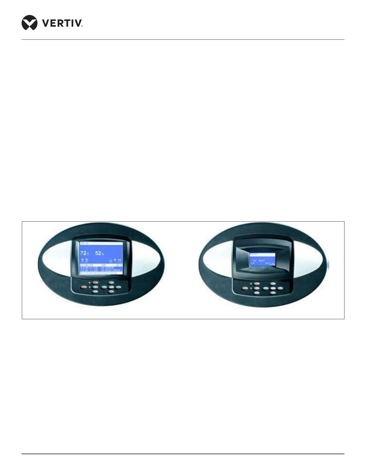
1.5.7. Large & Small Display
According to the requirement, Large & Small display are optional, using 480x480 pixel for large display and
128x64 pixels for small display. Both displays have 9 buttons on front board and use the multi-level password
to prevent unauthorized operation. Congure the setpoints of CRAC unit, displays the real-time values of the
CRAC’s status, active and history alarms.
Large Display Small Display
Figure 1-4 Large & Small Display
1.5.8. IS-UNITY-DP Card Assembly
By default, each card supports the Vertiv Protocol, Remote Service Delivery Protocol and HTTP Web. Control
and conguration capabilities are protected by an administrator’s user-name and password combination.
Optionally, status information can be password-protected. The default user-name for the administrator is
‘Liebert’ and the default password is also ‘Liebert’.
Page 21

Vertiv | Liebert® PEX3™ Series Precision Air Conditioner | User Manual 10
Product Overview
1.5.9. Smoke Detectors
Smoke detection system facilitates the data center to detect smoke in the unique air-ow environment. The
equipment room is outtted with hot and cold aisles, underoor and overhead spaces, each separated to
contain airow within the space. The active smoke detection technique triggers an alarm with the rst sign of
smoke.
1.5.10. Fire Detectors
The re detector can check the eld return air temperature. It triggers re alarm when the smoke level
continues to rise along with elevated room temperature, or the temperature is too high and reaches the re
alarm threshold. The primary purpose of the sensor is to examine the air temperature and to initialize the
anti-re measures installed in the facility.
1.5.11. Supply Air Pressure Sensor
Supply Air Pressure Sensor is only used for downow units. It detects the static pressure under the oor of
equipment room. The controller can read the values of static pressure.
1.5.12. Supply Air Temperature Sensor
Supply Air Temperature Sensor is used to modulate the heating and cooling eect of the unit by controlling
the supply air temperature through plenum. Temperature limits are eld adjustable via display interface. The
heating or cooling warning activates when the temperature exceeds the thresholds.
According to the requirements, Liebert PEX3 series can be provided without heating and humidication
options.
1.6. Refrigerant Requirement
The unit has a specically designed air conditioning system that requires a desired per-specied quality of
refrigerant (R410A) to perform continuously at the most optimum eiciency. For the details on the quantity of
refrigerant to be charged inside the system refer “Section 1.6.1”.
• Do not use inferior quality refrigerant.
• For any consequences resulting from inferior quality refrigerant, Vertiv does not assume warranty
responsibility.
Page 22
Vertiv | Liebert® PEX3™ Series Precision Air Conditioner | User Manual 11
Product Overview
1.6.1. Charging Refrigerant
Air-cooled series
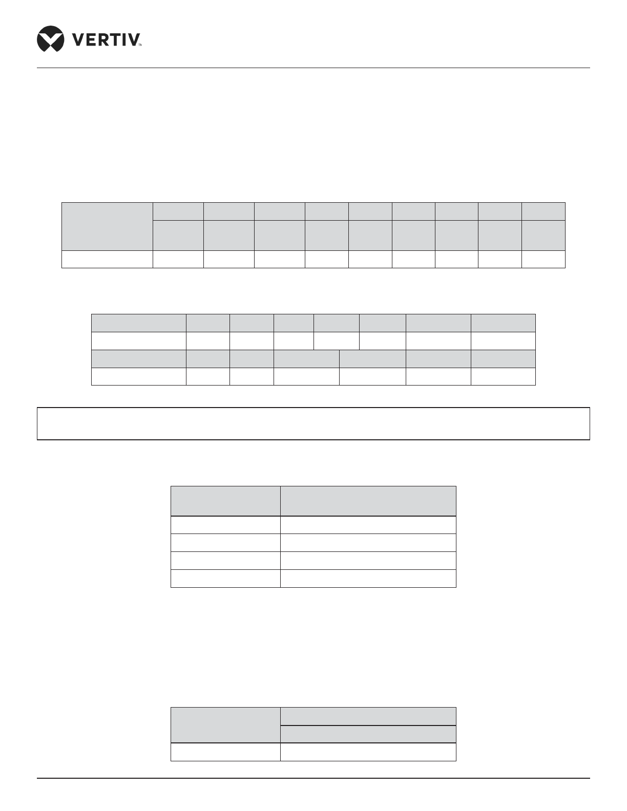
The Liebert PEX3 air-cooled series air conditioner is charged in the factory with 2 bar nitrogen for shipping.
Table 1-3 and Table 1-4 show the standard refrigerant charge for indoor and outdoor unit respectively.
Table 1-3 Indoor Refrigerant Charge (Unit: kg)
Indoor Model
P1030 P1040 P1050 P1050 P2060 P2070 P2080 P2090 P2100
Single
Circuit
Single
Circuit
Single
Circuit
Double
Circuit
Double
Circuit
Double
Circuit
Double
Circuit
Double
Circuit
Double
Circuit
Standard Charge 3.03 3.32 3.32 2x1.66 2x3.03 2x3.03 2x3.32 2x3.32 2x3.32
Table 1-4 Outdoor Refrigerant Charge (Unit : kg)
Outdoor Model LSF38 LSF42 LSF52 LSF62 LSF70 LSF76 LSF85
Standard Charge 2.99 4.65 6.19 5.64 5.64 7.30 9.73
Outdoor Model LDF76 LDF85 LVC088SE4 LVC106SE4 LVC140SE4 LVC152SE4
Standard Charge 2x3.65 2x4.87 2x4.79 2x6.39 2x6.10 2x7.19
Refrigerant Charge = Charge of Indoor Unit + Charge of Outdoor Unit + (Refrigerant Charge per Unit
Length of Liquid Pipe x Length of Extended Pipe)
Table 1-5 Amount of Refrigerant per Unit Length of Liquid Pipe (Unit: kg/m)
Liquid Pipe OD
(mm)
Refrigerant Charge per Unit
Length of Liquid Pipe (kg/m)
16 0.17
19 0.24
22 0.32
25 0.42
Water-cooled series
The Liebert PEX3 Water-cooled series air conditioner is charged in the factory with 1 bar to 2 bar nitrogen for shipping.
Table 1-6 show the standard refrigerant charge for the unit on-site.
Table 1-6 Indoor Refrigerant Charge Water-cooled (Unit: kg)
Indoor Model
P1030
Single Circuit
Standard Charge 4.0
Page 23
Vertiv | Liebert® PEX3™ Series Precision Air Conditioner | User Manual 12
Product Overview
1.7. Storage & Operating Environment Requirements
Refer Table 1-7 & Table 1-8 for storage environment and operating environment requirement.
Table 1-7 Storage Environment Requirements
Item Requirement
General requirements Clean room (no dust)
Environment humidity Less than 95% RH (30 °C)
Ambient temperature -25 °C to +55 °C
Storage time
Total transportation and storage time should not exceed six months, otherwise
the performance of the system needs to be re-calibrated.
Table 1-8 Operating Environment Requirements
Item Requirement
Ambient temperature
Indoor temperature: 18 ºC to 35 ºC, Outdoor (air cooling): -15 °C to +45 °C, the
minimum operating of outdoor is -35 °C, when equipped with low temp kit.
Cooling water inlet temperature: 10 ºC to 34 ºC
Protection level (cooling unit) IP20
Altitude <1000 m, derating is required when located altitude is above 1000 m
Operation voltage range 400 V, 3 Ph + N~50 Hz
Please contact Vertiv local representative when operating in the following conditions.
1. The voltage of the air conditioning unit is beyond the range of the operating voltage.
2. The altitude is higher than 1000 m.
3. If the operating condition is not as per Table 1-8.
Page 24
Vertiv | Liebert® PEX3™ Series Precision Air Conditioner | User Manual 13
Installation
Chapter 2: Installation
The Installation process consists of the following procedures, namely:
• Pre-installation
• Installation Preparation
• Mechanical Installation
• Electrical Installation
2.1. Pre-installation
2.1.1. Transportation & Movement
Railways and shipping are the preferable transport options for the CRAC. If transport by rail or by ship is
unavailable, transport by road is recommended. When selecting road transport, roads without too many bumps
are highly recommended.
• Liebert PEX3 unit is heavy, it is recommended to use the mechanical equipment like electrical forklift to
move the unit.
• Move the equipment to the location near the installation site.
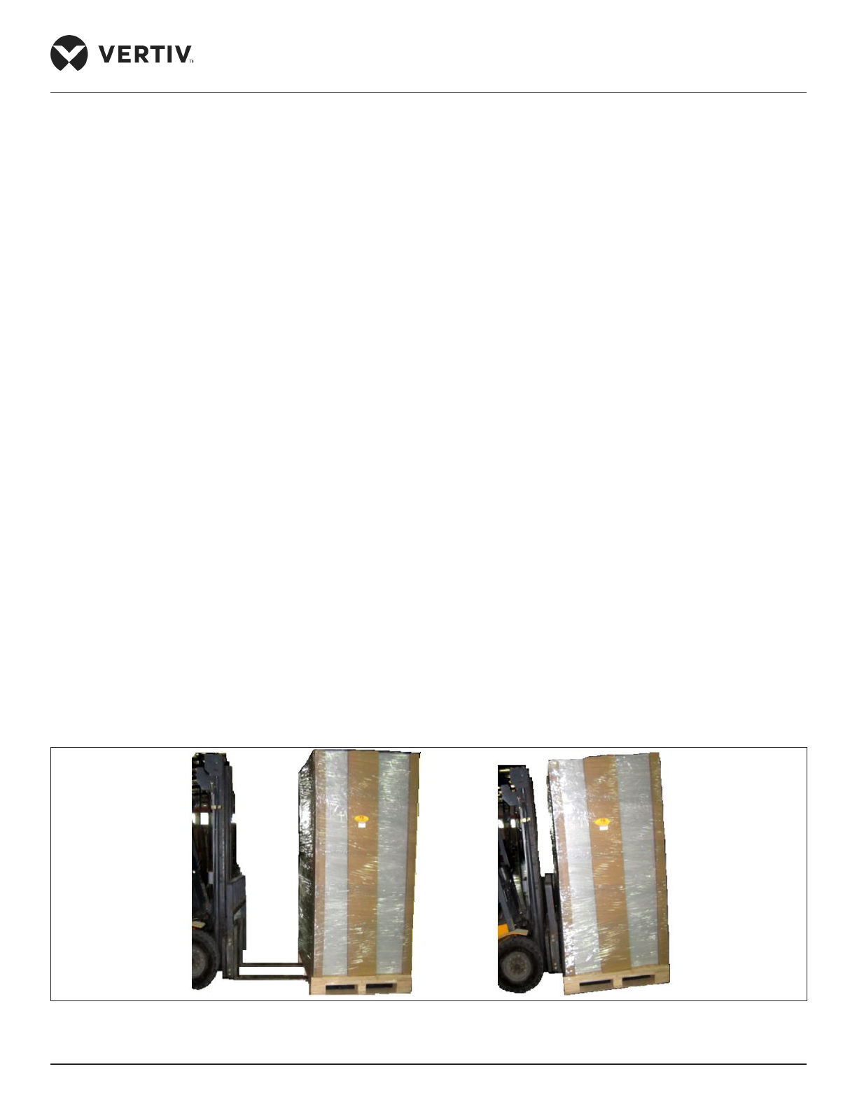
• If an electric forklift is used, insert the tines of the forklift below the pallet as displayed in Figure 2-1.
• Figure 2-1 shows how the forklift tines are inserted underneath the pallet and shows in the same picture the
illustration to the right that the tines should be aligned with the center of gravity to prevent the equipment
from falling over.
Figure 2-1 Moving an Equipment Using a Forklift Truck
Page 25
Vertiv | Liebert® PEX3™ Series Precision Air Conditioner | User Manual 14
Installation
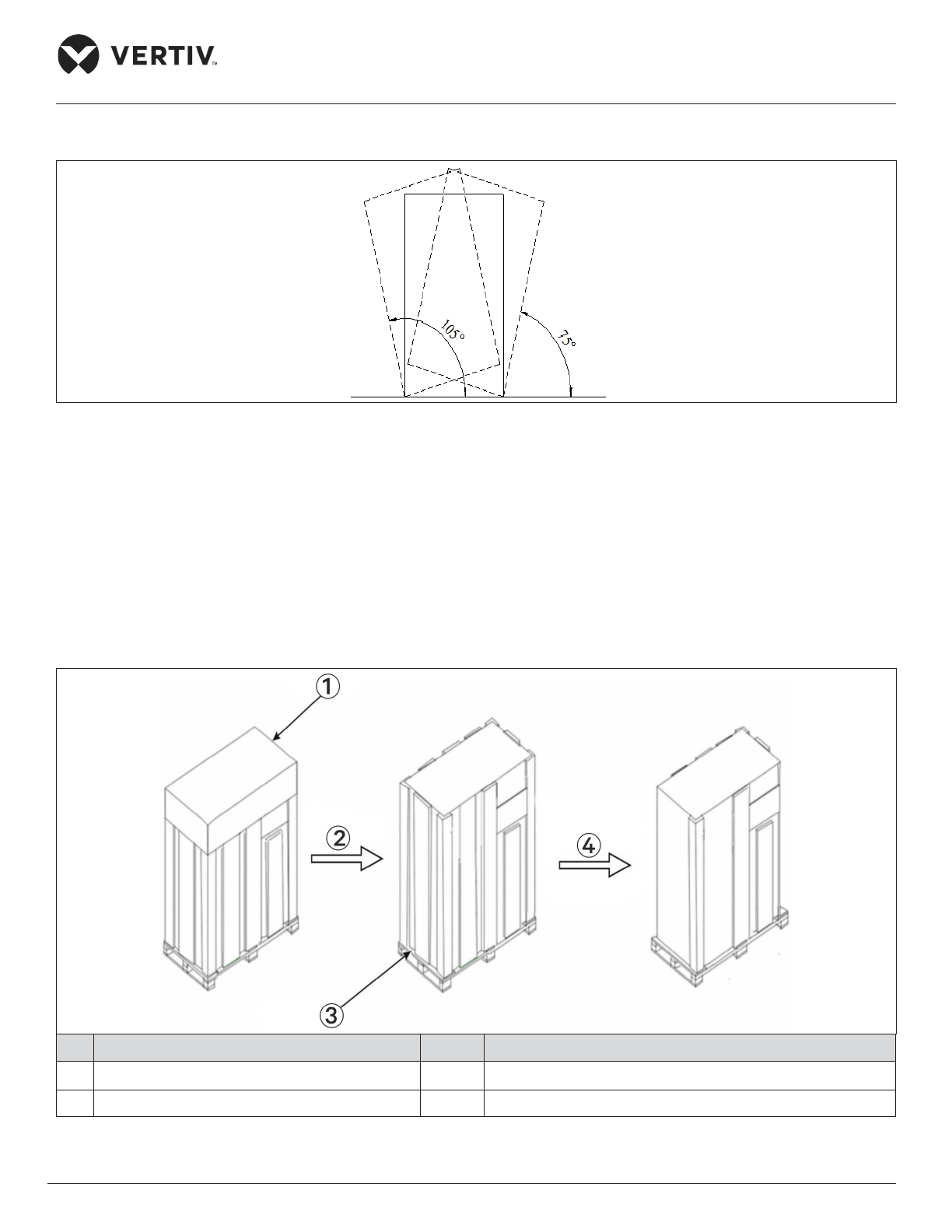
While moving the indoor unit, keep the obliquity within the range of 75° to 105°, as shown in Figure 2-2.
Figure 2-2 Obliquity of the System
2.1.2. Unpacking
Move the equipment to the location nearest to the nal installation site and unpack it. Follow the procedures
below for unpacking.
• Removal of Paper Packaging
Remove the packaging tape and carton at rst, then remove the top cover followed by dismantling the unit
on the sealing plastic, nally, remove the Honey Comb Paper Board. For better understanding see Figure 2-3.
No. Description No. Description
1 Top Cover 3 Honey Comb Paper Board
2 Remove Top Cover 4 Remove sealing plastic lm and Honey Comb Paper Board
Figure 2-3 Removal of Honey Comb Paper Board
Page 26
Vertiv | Liebert® PEX3™ Series Precision Air Conditioner | User Manual 15
Installation
• Removal of Wood Packaging
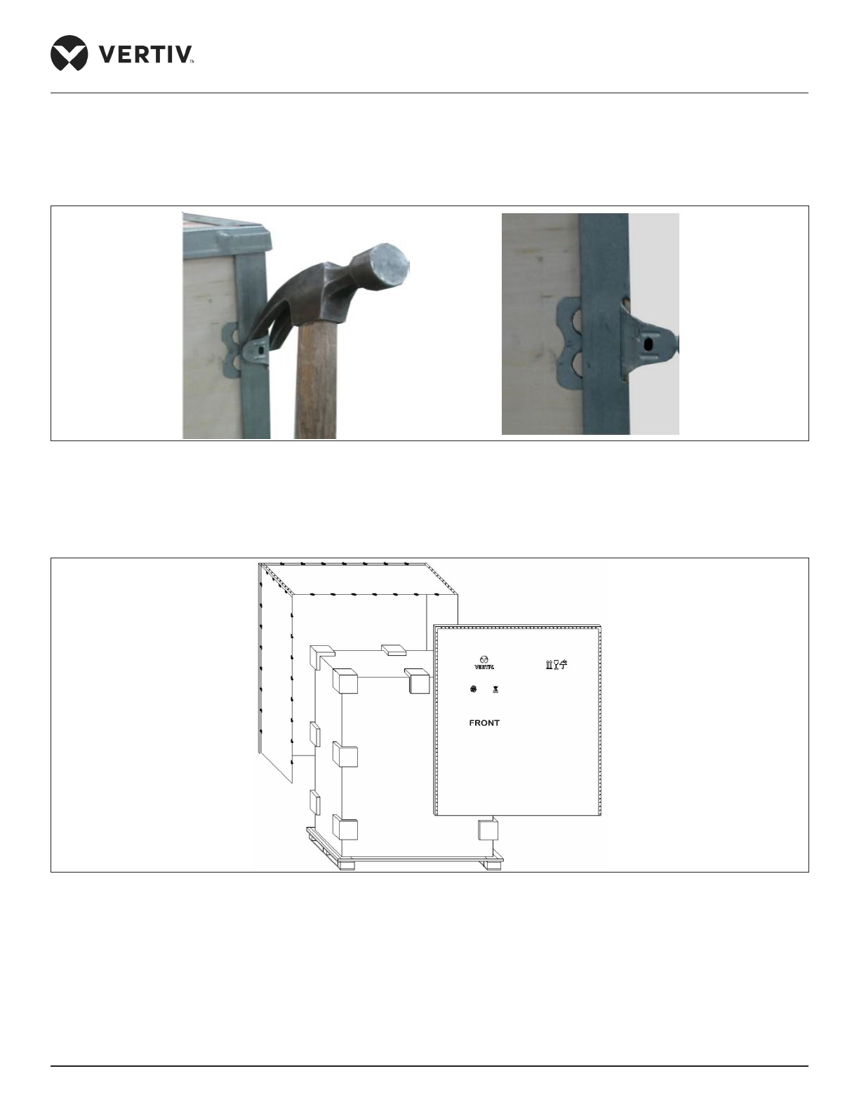
Use a claw hammer or straight screwdriver to straighten the connection hook that holds the side panels to the
top cover, as shown in Figure 2-4.
Figure 2-4 Straightening the Hook
Firstly, straighten all the hooks that hold side panel-I and remove side panel-I. Then straighten all the hooks that
hold side panel-II and remove side panel-II. At last remove top cover-III, as shown in Figure 2-5.
Figure 2-5 Removing Side Panel and Top Cover
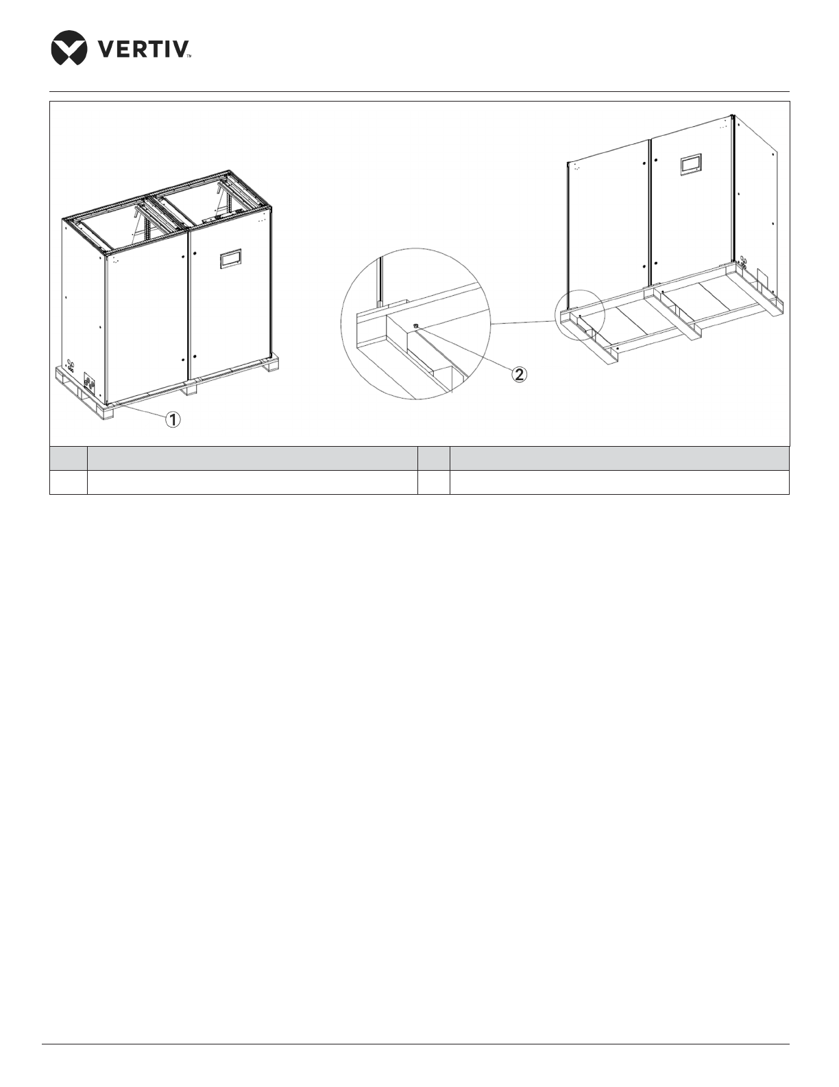
• Remove the Base Pallet
The unit is xed onto the base pallet with M8×65 bolts or M8×90 screw, as shown in Figure 2-6 for air-cooled,
it will be same for water-cooled model (single bay ) as well. Use a 17 mm open-end spanner, ratchet spanner or
sleeve to remove the xing bolts.
Page 27
Vertiv | Liebert® PEX3™ Series Precision Air Conditioner | User Manual 16
Installation
No. Description No. Description
1 Pallet Screw Position Marking 2 Pallet Screw
Figure 2-6 Pallet Screws Fixing Position for Air Cooled
2.1.3. Inspection
Check that the ttings are complete and the components are intact against the packing list. If any parts
are missing or damage is found, please report immediately to the local oices of the carrier and Vertiv local
representative
2.2. Installation Preparation (Site Preparation)
PEX3 series is streamlined for maintaining a favorable environment for equipment rooms, computer rooms,
and similar ecosystems. Strict adherence to the installation procedures is mandatory to ensure that the air
conditioner is installed properly.
2.2.1. Equipment Room Requirements
Before installation, the equipment room must be prepared to ensure a smooth operating ow and to achieve
the expected results. The equipment room must meet the standards, to get proper ventilation and heating.
The design specications for the air conditioners must be ideal and should match the energy-eicient design
standards.
Page 28

Vertiv | Liebert® PEX3™ Series Precision Air Conditioner | User Manual 17
Installation
Following are the requirements to maintain a favorable room environment prior to the installation.
The Equipment room should have suitable and eective heat insulation.
• The equipment room should have a sealed and damp-proof layer. Polyethylene lm should be used for the
damp proof layer of the ceiling and walls. Alternatively, moisture-proof paint can be used to simulate the
same eect akin to Polyethylene. It is important to ensure that the coating on the concrete wall and oor is
damp-proof.
• Outdoor air signicantly increases the load of heating, cooling, humidication, and dehumidication.
Therefore, all the doors and windows must be closed. Gaps and seams must be very narrow to prevent
the outdoor air from entering the equipment room. It is an industry best practice to keep the inltration of
the outdoor air below 5% of the total indoor airow. Apply appropriate thermal insulation and antifreeze
measures for outdoor water pipes to avoid poor drainage and insuicient water supply caused by freezing.
• Vertiv recommends that the site preparation is dened as per the requirements. However, if these
requirements are not met, Vertiv suggests that rectications to be made on the site in order to comply with
the specied requirements and conditions.
• However, if the rectications or modications are not implemented, then Vertiv does not guarantee the
accuracy and precision of the temperature and humidity provided by the unit.
2.2.2. Installation Space Requirements
Adequate installation space for the indoor unit must be provided. The indoor unit of the PEX3 DX product must
be installed on the oor of Equipment room or Computer Room and the outdoor unit must be installed outside
data center, open to the external ambient.
• Do not use the indoor unit in the open and severe outdoor environment.
• Avoid locating the indoor unit in concave or narrow areas, which can obstruct the airow, shorten the
cooling cycle and result in air return short cycle and air noise.
• Avoid locating multiple indoor units close to each other. This can result in short cycle of air and create
load imbalance.
• Do not install the unit within the vicinity of any other precision cooling equipment to prevent the leakage
of condensed water produced due to imbalance load condition.
• Do not install other devices (such as smoke detector) over the indoor cabinet
Page 29
Vertiv | Liebert® PEX3™ Series Precision Air Conditioner | User Manual 18
Installation
2.2.3. Maintenance Space Requirement
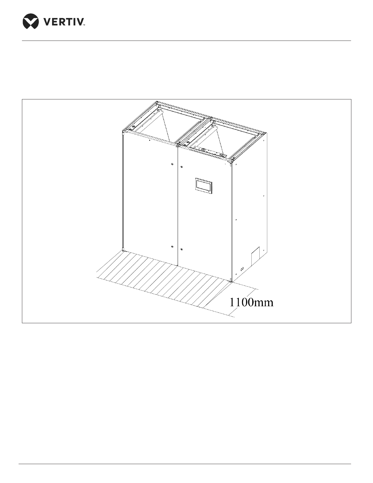
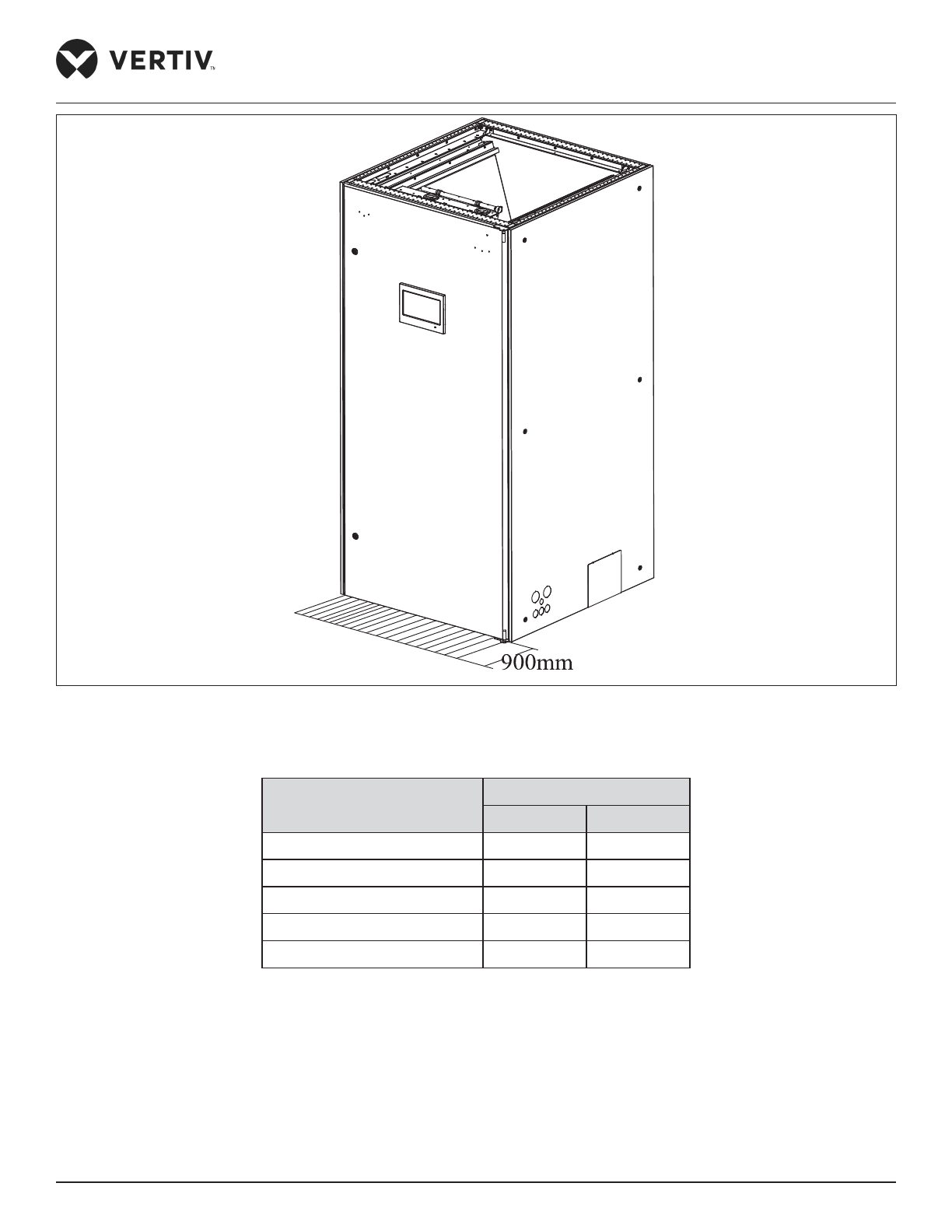
When installing the unit, a minimum maintenance space of 1100 mm must be reserved in-front of the air
conditioning unit. The required maintenance space for air-cooled unit is shown in Figure 2-7 and for
water-cooled unit see Figure 2-8. Refer Table 2-1 for maintenance spaces of both types of unit models.
Figure 2-7 Maintenance Space of Unit for Air-cooled Unit
Page 30
Vertiv | Liebert® PEX3™ Series Precision Air Conditioner | User Manual 19
Installation
Figure 2-8 Maintenance Space of Unit for Water-cooled Unit
Table 2-1 Normal Maintenance Space (unit: inch/mm)
Product Type
Front
mm inch
P1030 900 35.4”
P1030 (For Water-cooled) 900 35.4”
P1040~P1050 1100 43.3”
P2060~P2070 900 35.4”
P2080~P2100 1100 43.3”
Page 31
Vertiv | Liebert® PEX3™ Series Precision Air Conditioner | User Manual 20
Installation
2.2.4. Installation Tools
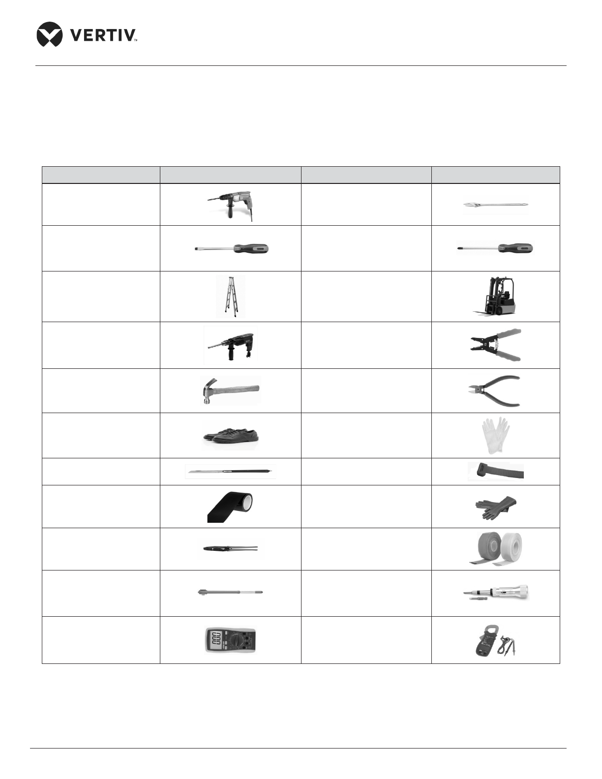
The following Table 2-2 shows the generic tool sets and utilities used in the installation and maintenance
process.
Table 2-2 List of Generic Tools
Name Drawing Name Drawing
Electric hand drill Adjustable wrench
Slotted screwdriver Cross head screwdriver
Stepladder Forklift
Drill Wire cutting pliers
Claw hammer Diagonal cutting pliers
Insulating shoes Anti-static gloves
Electrician knife Cable ties
Insulating tape Insulating gloves
Crimping pliers Heat shrinkable tube
Insulated torque wrench Torque screwdriver
Multi-meter Clip-on ammeter
The tools mentioned in Table 2-2 are generic and commonplace; however, depending on various factors such as
site environment, local rules and regulations, cables, installation equipment, and on-site electrical connections
these tools may vary in a real- time scenario.
Page 32
Vertiv | Liebert® PEX3™ Series Precision Air Conditioner | User Manual 21
Installation
Ensure that the tools used in the installation, operation, and maintenance processes are well insulated.
2.2.5. System Arrangement during Installation
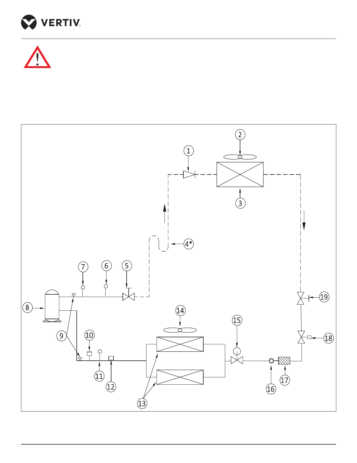
The piping for the refrigerant is needed for the indoor and outdoor unit of the air-cooled system. The system
arrangement diagram of the refrigeration system is shown in Figure 2-9.
Figure 2-9 Air-cooled System Arrangement Diagram
Page 33
Vertiv | Liebert® PEX3™ Series Precision Air Conditioner | User Manual 22
Installation
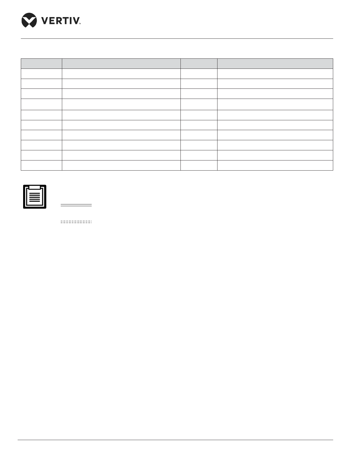
List of the components of system arrangement diagram (Figure 2-9) is given in the below table.
No. Description No. Description
1 Check valve 11 LP switch
2 EC/ AC fan 12 Suction temperature sensor
3 Condenser Coil 13 Evaporator coil
4*
Oil trap (mounted one at every rise of 7.5 m) 14 EC fan
5 Shuto valve 15 Electronic Expansion Valve
6 Discharge temperature switch 16 Sight glass
7 HP Switch 17 Filter dryer
8 Scroll Compressor 18 Solenoid valve
9 Schradar Valve 19 Shuto valve
10 LP transducer
The following points should be considered before checking out the overall layout diagram
• : Factory piping
• : Field piping (by technical personnel)
• The single system is used as an example.
• Components (marked with *) are not supplied by Vertiv but are recommended for proper circuit operation
and maintenance.
Page 34
Vertiv | Liebert® PEX3™ Series Precision Air Conditioner | User Manual 23
Installation
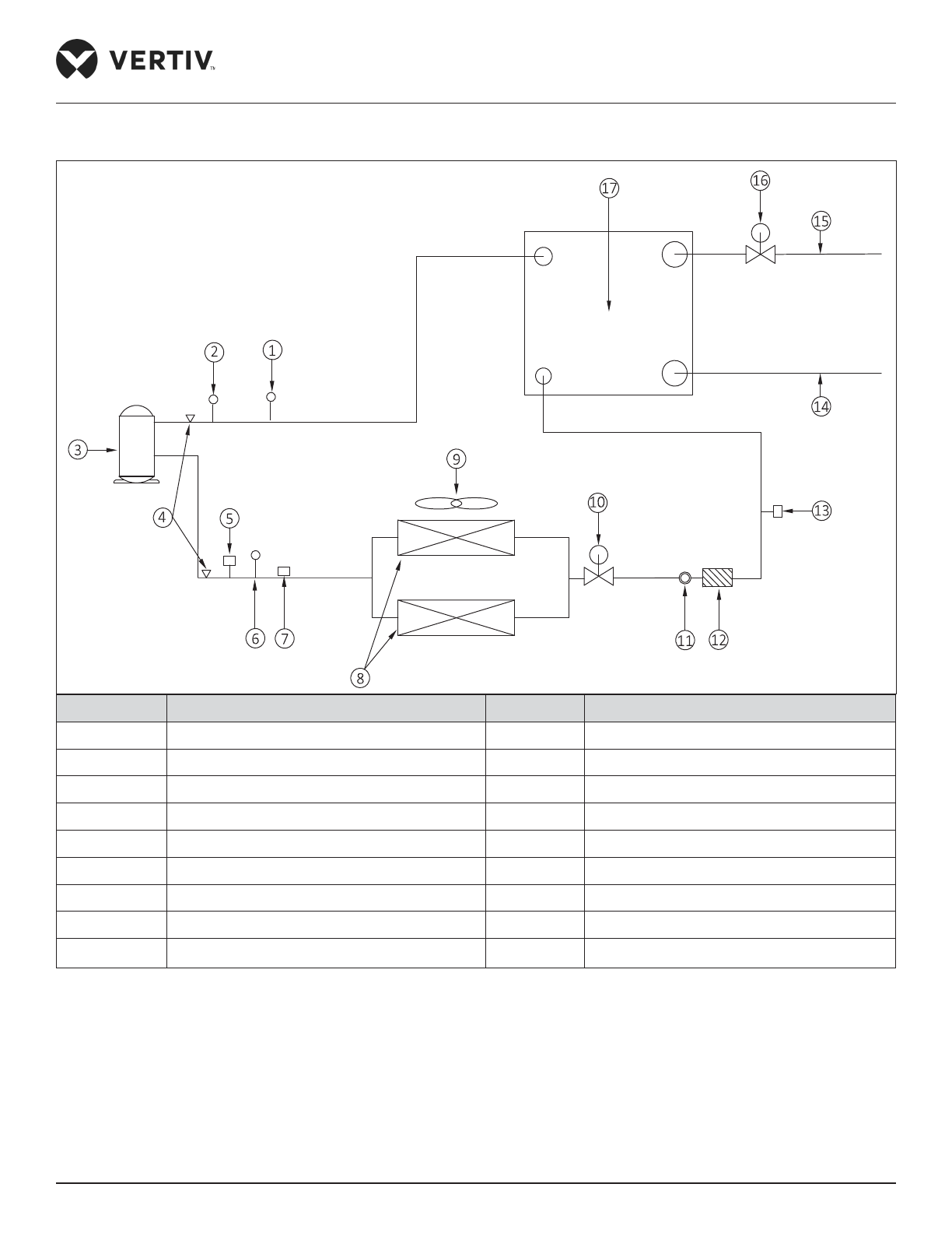
The system arrangement diagram of the refrigeration system for water-cooled is shown in Figure 2-10
No. Description No. Description
1 Discharge temperature switch 10 Electronic expansion valve
2 HP switch 11 Sight glass
3 Scroll compressor 12 Filter dryer
4 Schrader valve 13 HP transducer
5 LP transducer 14 Welding port of water inlet
6 LP switch 15 Welding port of water outlet
7 Suction temperature sensor 16 Motorized ball valves (MBV)
8 Evaporator coil 17 BPHE
9 EC fan
Figure 2-10 Water-cooled System Arrangement Diagram
Page 35
Vertiv | Liebert® PEX3™ Series Precision Air Conditioner | User Manual 24
Installation
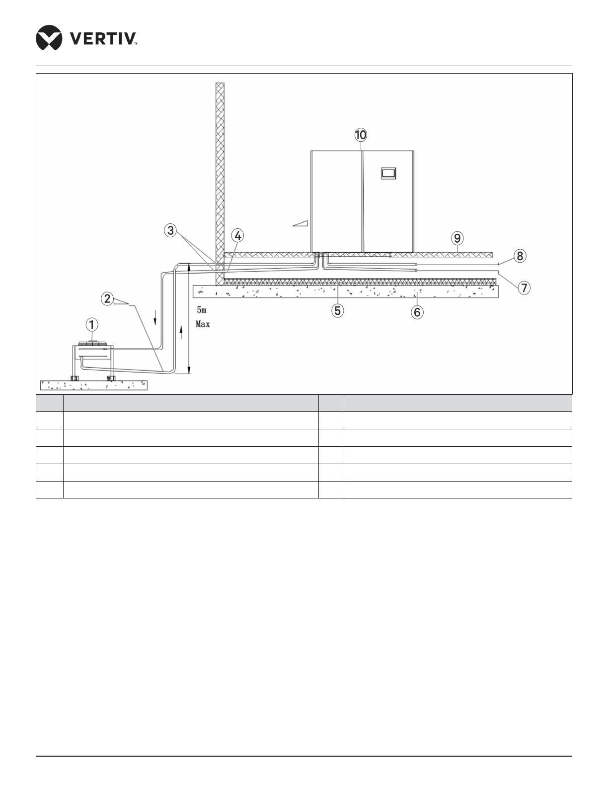
2.2.6. System Installation Mode
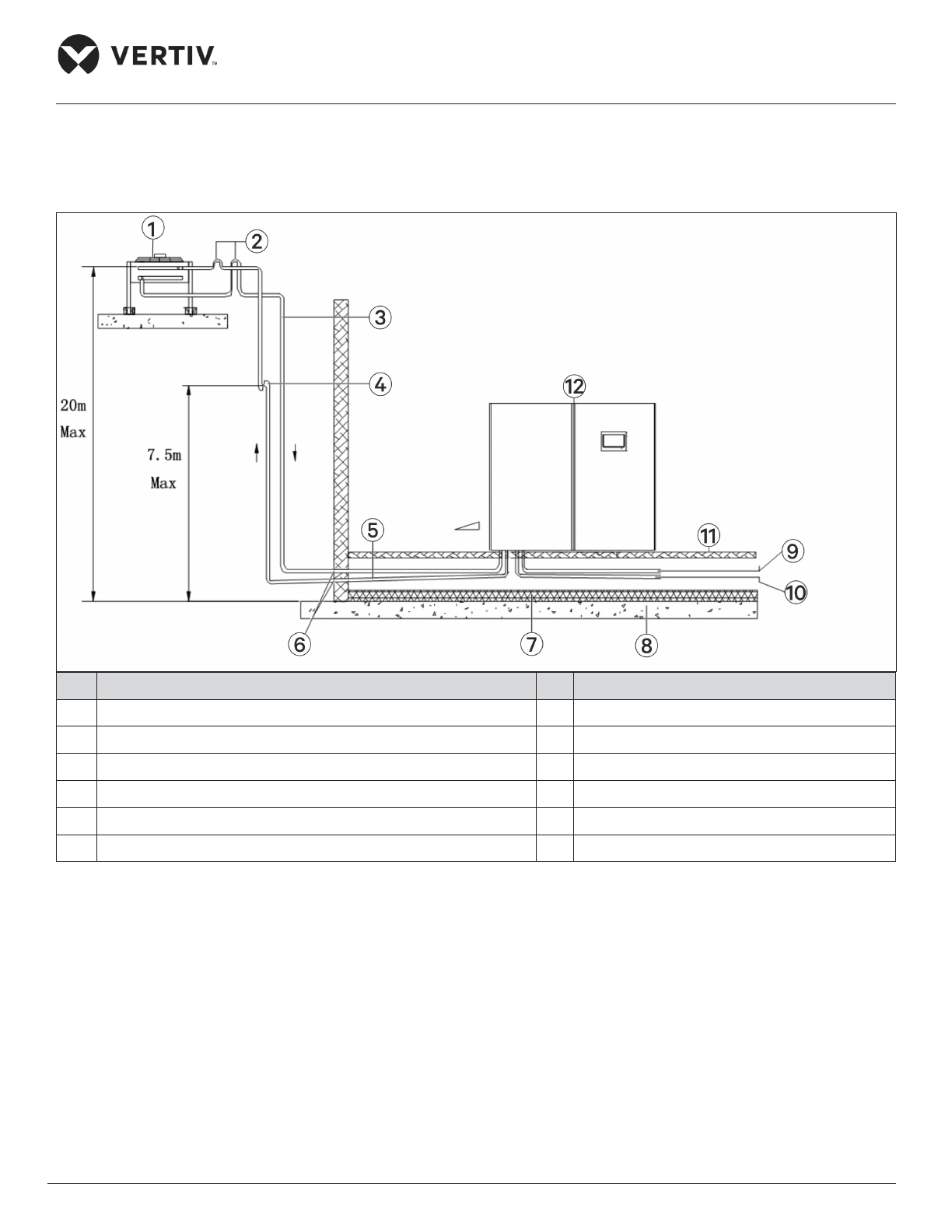
The system installation schematic diagram explains the process of installation for the outdoor unit.
No. Description No. Description
1 Outdoor unit 7 Thermal isolated layer under oor
2 Inverted traps (higher than the top copper pipe of condenser) 8 Slob
3 Liquid pipe (avoid direct sunshine) 9 Humidier supply pipe
4 Oil trap (oil storage bend) 10 Condensate drain pipe
5 Discharge pipe slope 11 Raised oor
6 Sealed 12 Indoor unit
Figure 2-11 The Outdoor Unit is Placed Higher than the Compressors during Installation
The outdoor unit should be installed at higher position than the compressor, therefore, an inverted backbend is
connected to the discharge line and the liquid line of the condenser. The modication is essential as it prevents
the liquid refrigerant from owing back once the compressor stops. The top end of the inverted backbend
should be installed higher than the ultimate level of the copper pipe of the outdoor unit. However, if the outdoor
unit is installed lower than the compressor, then no modication is required.
The illustration in Figure 2-11 depicts the schematic diagram of system installation when the outdoor unit is
installed at a higher level than the compressor and Figure 2-12 when the outdoor unit is installed at a lower level
than the compressor.
Page 36
Vertiv | Liebert® PEX3™ Series Precision Air Conditioner | User Manual 25
Installation
No. Description No. Description
1 Outdoor unit 6 Slob
2 Liquid pipe slope 7 Condensate drain pipe
3 Sealed 8 Humidier supply pipe
4 Discharge Pipe slope 9 Raised oor
5 Thermal isolation layer under oor 10 Indoor unit
Figure 2-12 The Outdoor Unit is Placed Lower than the Compressor during Installation
Page 37
Vertiv | Liebert® PEX3™ Series Precision Air Conditioner | User Manual 26
Installation
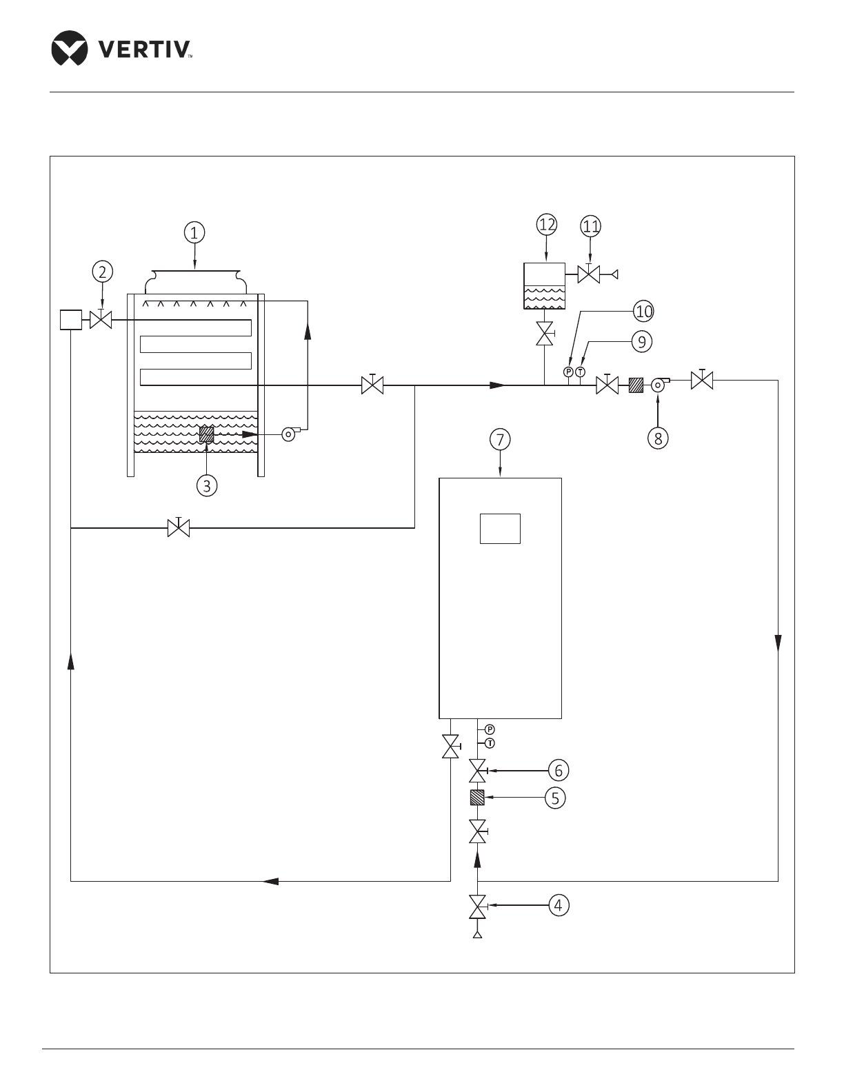
Figure 2-13 shows the arrangement of cooling water system, which requires the water hotter than 10 °C. Use
heaters if the water source in site cannot meet this requirement. The cooling tower should be a cooled loop
system.
Figure 2-13 Arrangement of Water-cooled System
Page 38
Vertiv | Liebert® PEX3™ Series Precision Air Conditioner | User Manual 27
Installation
List of the components of system arrangement diagram (Figure 2-13) is given in the below table.
No. Description No. Description
1 Closed cooling tower 7 Liebert PEX3 unit
2 Exhaust water valve 8 Pump
3 Strainer 9 Temperature gauge
4 Drain valve 10 Manometer
5 Filter 11 Supplementary valve
6 Ball valve 12 Expansion water tank
2.3. Mechanical Installation
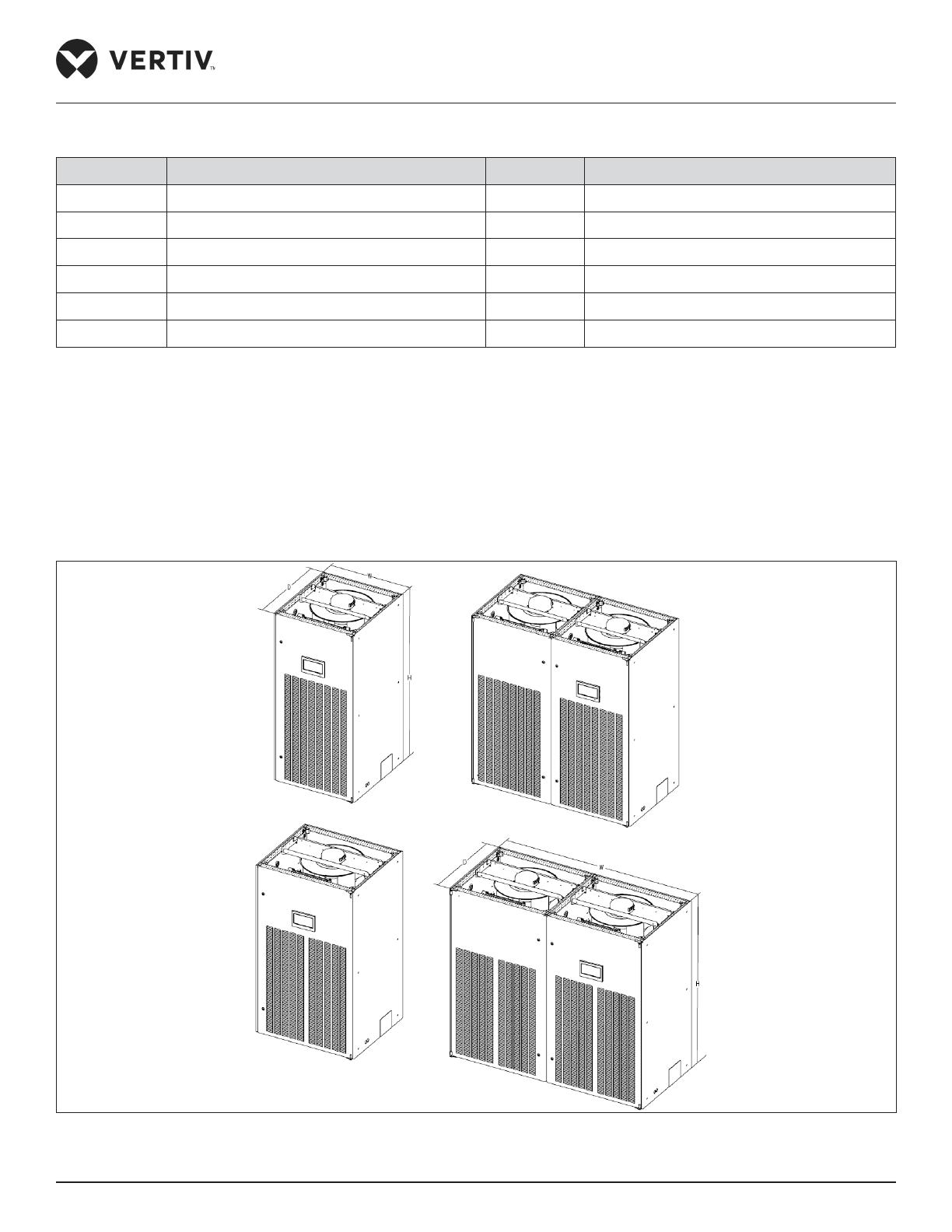
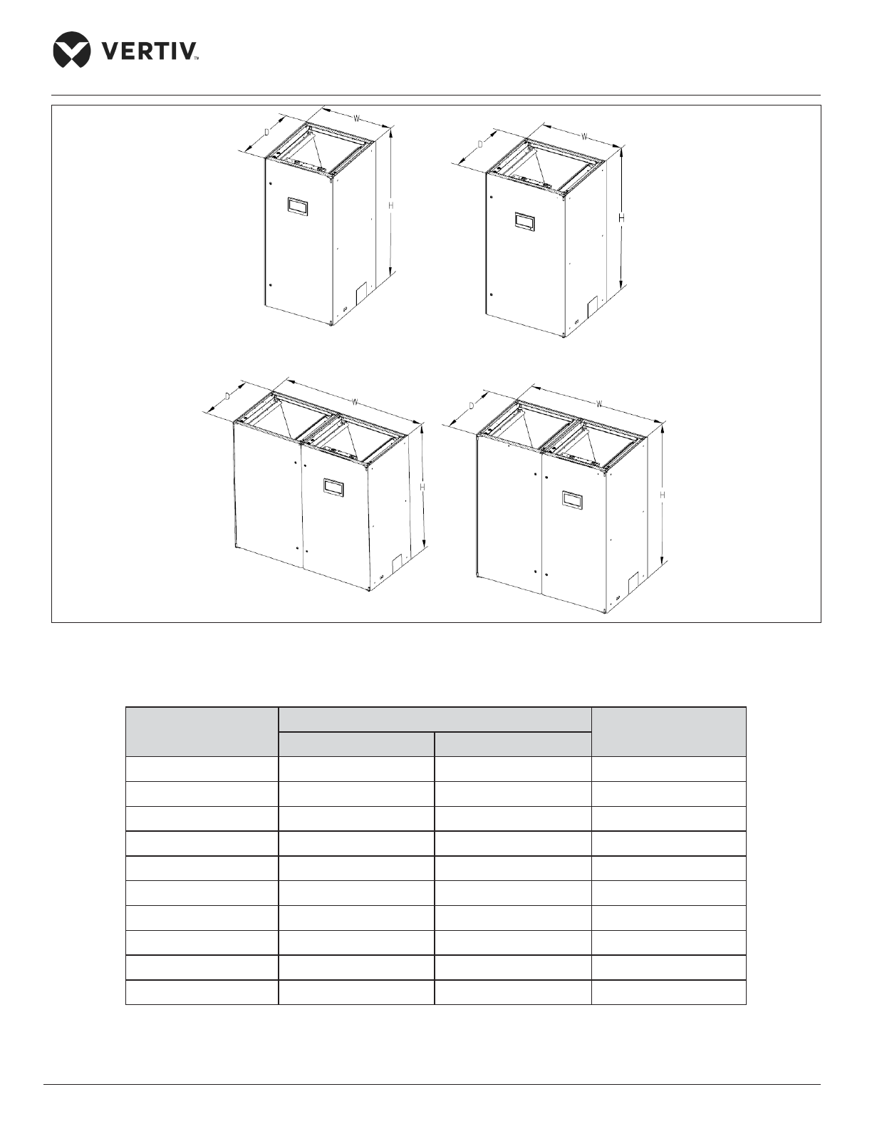
2.3.1. Indoor Unit Size and Weight (Product Dimension)
The dimensions and operational weight of the indoor units are depicted in Figure 2-14 & Figure 2-15 and
Table 2-3 respectively.
Figure 2-14 Upflow Indoor Unit
Page 39
Vertiv | Liebert® PEX3™ Series Precision Air Conditioner | User Manual 28
Installation
Figure 2-15 Downow Indoor Unit
Table 2-3 Indoor Unit Size and Weight
Product Number
Dimensions (W×D×H)
Operational Weight
(kg)
mm inch
P1030U/ DA 930 × 995 × 1975 36.6”×39.2”×77.7” 360
P1030U/ DW 930 × 995 × 1975 36.6”×39.2”×77.7” 390
P1040 1130 × 995 × 1975 44.5”×39.2”×77.7” 420
P1050 (S) 1130 × 995 × 1975 44.5”×39.2”×77.7” 440
P1050 (D) 1130 × 995 × 1975 44.5”×39.2”×77.7” 470
P2060 1830 × 995 × 1975 72.0”×39.2”×77.7” 660
P2070 1830 × 995 × 1975 72.0”×39.2”×77.7” 670
P2080 2230 × 995 × 1975 87.8”×39.2”×77.7” 740
P2090 2230 × 995 × 1975 87.8”×39.2”×77.7” 770
P2100 2230 × 995 × 1975 87.8”×39.2”×77.7” 780
Page 40
Vertiv | Liebert® PEX3™ Series Precision Air Conditioner | User Manual 29
Installation
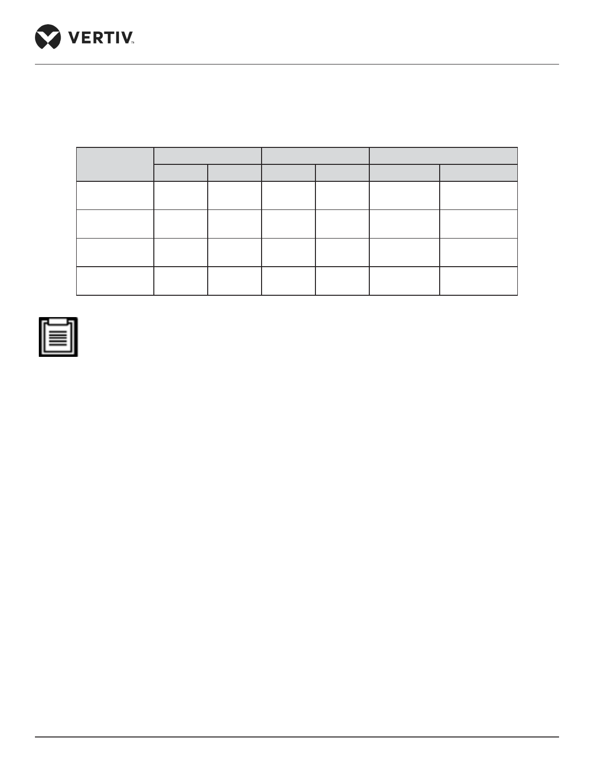
2.3.2. Plenum Dimensions (for Upow Unit)
The dimensions of the Plenum as follows, refer Table 2-4.
Table 2-4 Plenum Dimensions
Types
D (depth) W (width) H (height)
mm inch mm inch mm inch
P1030 995 39.2” 930 36.6”
400,
600 (optional)
15.8”,
23.6” (optional)
P1040~P1050 995 39.2” 1130 44.5”
400,
600 (optional)
15.8”,
23.6” (optional)
P2060 ~ P2070 995 39.2” 1830 72.1”
400,
600 (optional
15.8”,
23.6” (optional)
P2080 ~ P2100 995 39.2” 2230 87.8”
400,
600 (optional
15.8”,
23.6” (optional)
If the height of the plenum selected for air conditioner unit exceeds 23.6”/ 600 mm, consult Vertiv local
representative for non-standard requirement.
2.3.3. Dimension and Weight of Condenser
Refer to the “Liebert PEX Condenser User Manual” and “LVC Series Condenser User Manual”.
2.3.4. Base Plate Cut-out Position and Dimension
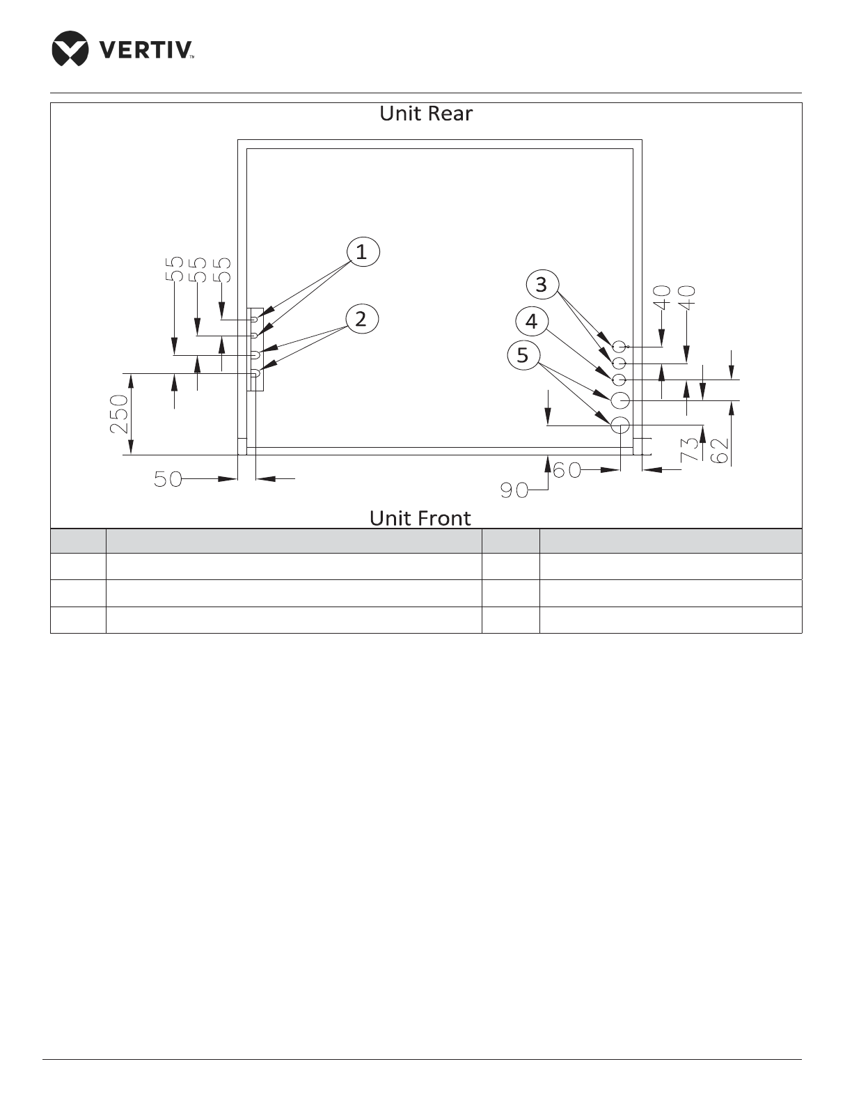
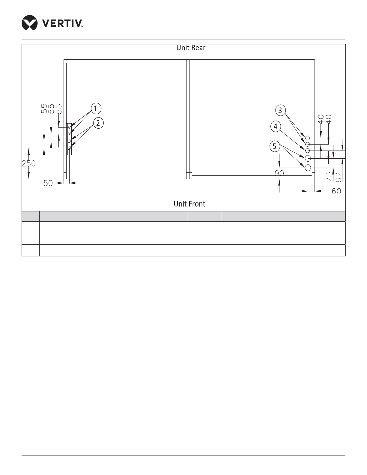
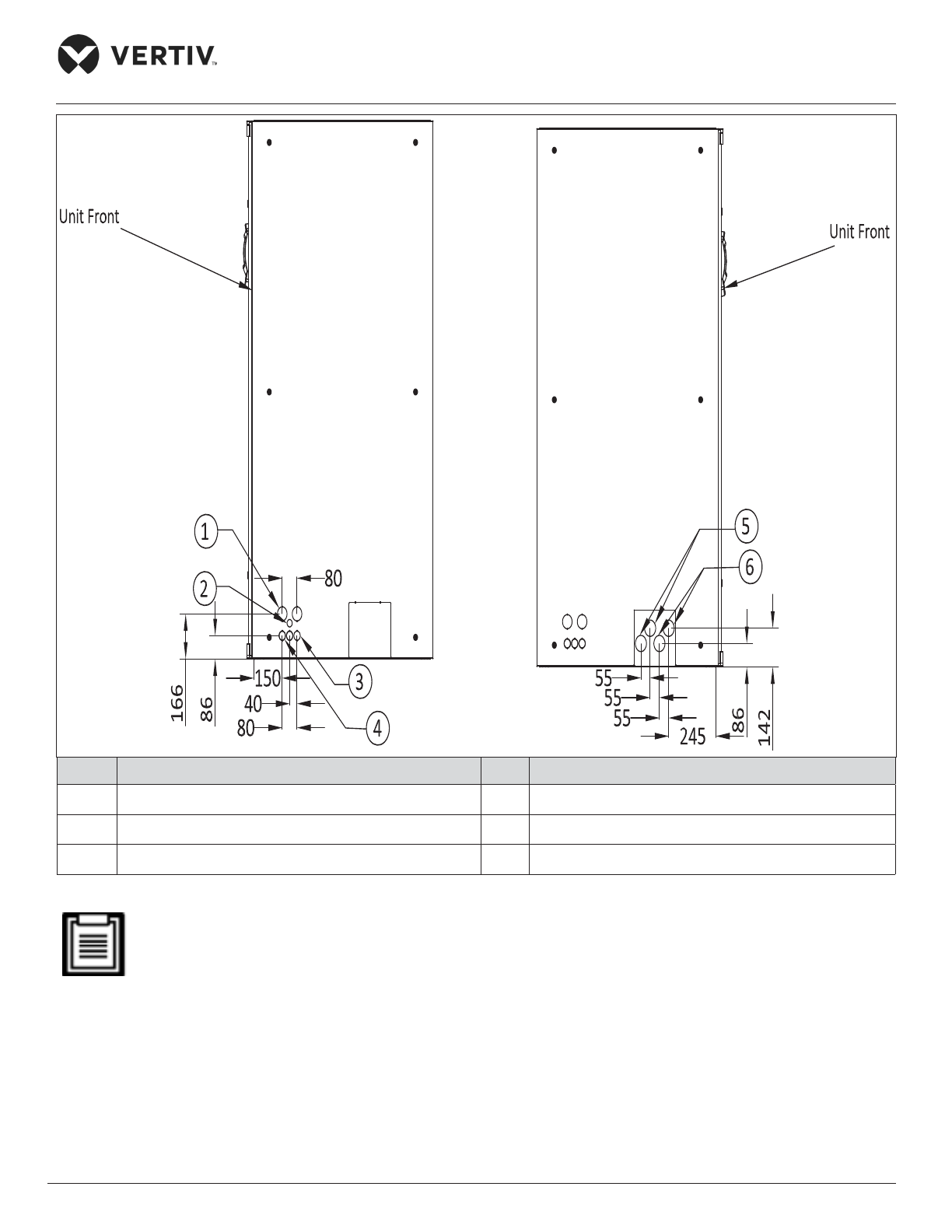
The cut-out position and dimensions are shown in Figure 2-16, Figure 2-17 and Figure 2-18.
Page 41
Vertiv | Liebert® PEX3™ Series Precision Air Conditioner | User Manual 30
Installation
No. Description No. Description
1 Liquid pipe inlet 4
Inlet of humidication inlet pipe ø35
2 Discharge outlet 5
Cable inlet ø50
3
Condensate drain outlet ø35
Figure 2-16 The Position of Pipe Bottom Outlet of Single Cabinet Unit (unit: mm)
Page 42
Vertiv | Liebert® PEX3™ Series Precision Air Conditioner | User Manual 31
Installation
No. Description No. Description
1 Liquid pipe inlet 4
Inlet of humidication inlet pipe ø35
2 Discharge outlet 5
Cable inlet ø50
3
Condensate drain outlet ø35
Figure 2-17 The Position of Pipe Bottom Outlet of Dual Cabinet Unit (unit: mm)
Page 43
Vertiv | Liebert® PEX3™ Series Precision Air Conditioner | User Manual 32
Installation
No. Description No. Description
1
Cable Entry ø52
4
Humidier inlet nozzle ø35
2
Single cable inlet ø25
5
Liquid pipe inlet ø60
3
Condenser drain pipe ø35
6 Discharge inlet
Figure 2-18 Left and Right Panel with Nozzle Position of Cut-out Location Dimensions (unit: mm)
The equipment has knock-outs, ensure to mount sleeve to the cable holes to avoid cutting of the cables.
Page 44
Vertiv | Liebert® PEX3™ Series Precision Air Conditioner | User Manual 33
Installation
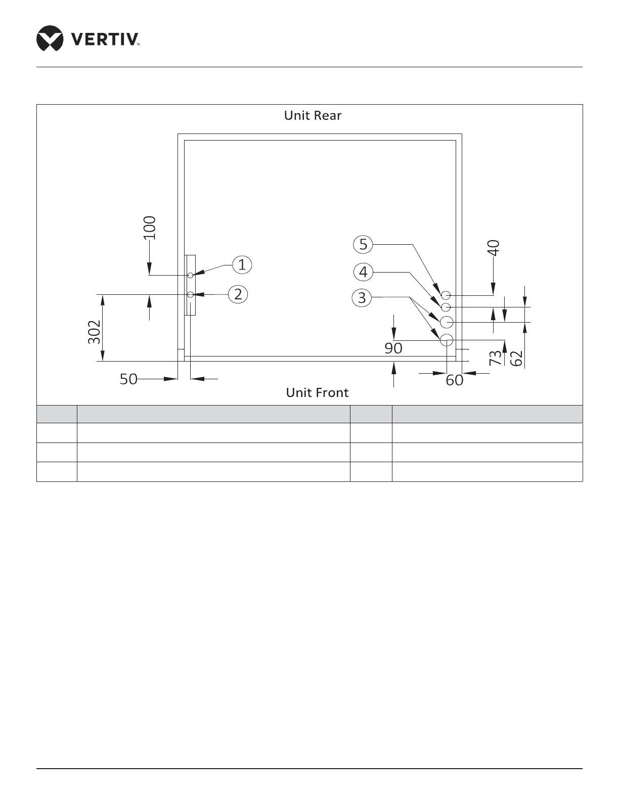
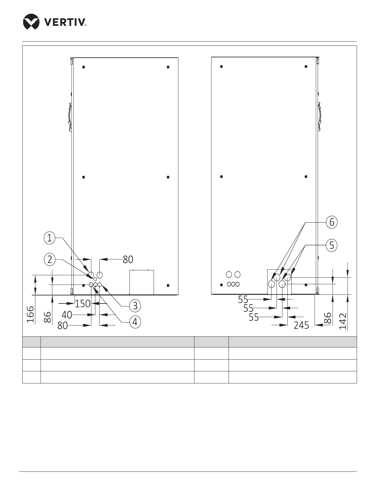
Figure 2-19 and Figure 2-20 show the cut-out position and dimensions of water-cooled unit.
No. Description No. Description
1
Water pipe inlet ø50
4
Inlet of humidication inlet pipe ø35
2
Water pipe outlet ø50
5
Condensate drain outlet ø35
3
Cable inlet ø50
Figure 2-19 The Position of Pipe Bottom Outlet of Single Cabinet Unit (unit: mm)
Page 45
Vertiv | Liebert® PEX3™ Series Precision Air Conditioner | User Manual 34
Installation
No. Description No. Description
1
Cable entry ø35
4
Humidication inlet nozzle ø35
2
Single cable inlet ø25
5
Water pipe outlet ø60
3
Condensate drain pipe ø35
6
Water pipe inlet ø60
Figure 2-20 Left and Right Panel with Nozzle Position of Cut-out Location Dimensions (unit: mm)
Page 46
Vertiv | Liebert® PEX3™ Series Precision Air Conditioner | User Manual 35
Installation
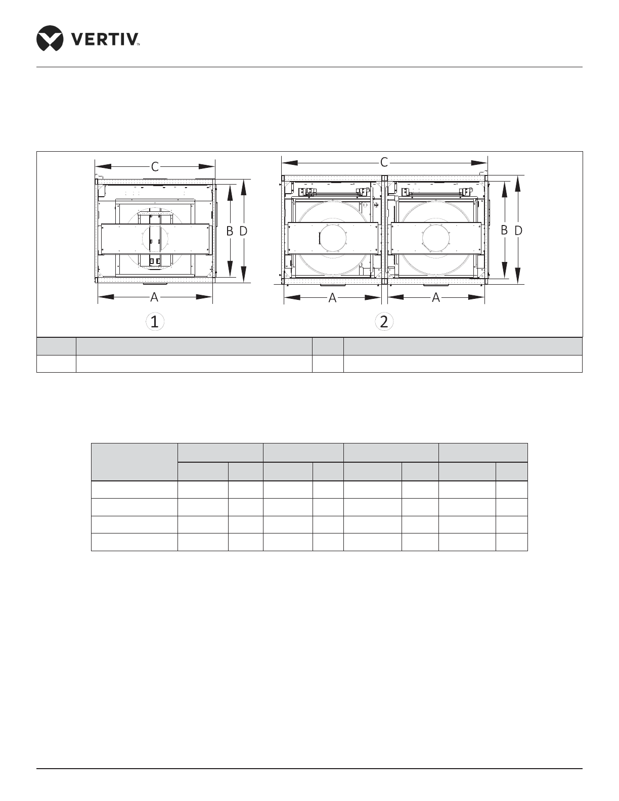
2.3.5. Position and Dimension of Air Outlet on Top Cover
The position and dimensions of air outlet on the top cover of upow for single bay (air-cooled/ water-cooled)
and two bay units are shown in Figure 2-21 and in Table 2-5 respectively.
No. Description No. Description
1 Top view of the single bay unit 2 Top view of the double bay unit
Figure 2-21 The Position of Air Outlet on Top Cover Upow Unit
Table 2-5 Dimensions of Air Outlet on Top Cover of Upow Unit
Types of Model
A B C
D
mm inch mm inch mm inch mm inch
P1030 850 33.5” 850 33.5” 900 35.4”
950 37.4”
P1040~P1050 1050 41.3” 850 33.5” 1100 43.3”
950 37.4”
P2060~P2070 850 33.5” 850 33.5” 1800 70.9”
950 37.4”
P2080~P2100 1050 41.3” 850 33.5” 2200 86.6”
950 37.4”
Page 47
Vertiv | Liebert® PEX3™ Series Precision Air Conditioner | User Manual 36
Installation
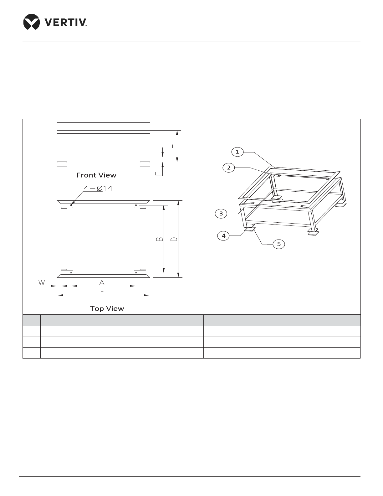
2.3.6. Indoor Installation
• Floor Stand
The oor stand is to be prepared by the installation team according to the dimensions, weight, and height of the
unit to ensure that the structure is rigid, the oor stand should be sized according to Figure 2-22 for single bay
unit (Air/ Water-cooled Unit) and Figure 2-23 for two bay unit and Table 2-6.
No. Description No. Description
1 Upper rubber damping pad (5 mm thick) 4 Bottom plate (100 mm x 100 mm x 5 mm, 4PCS)
2 Fixed steel plate (3 mm thick 4PCS) 5 Bottom rubber cushion (10 mm thick, 4PCS)
3 Incline tie joint (angle steel 3 mm thick)
Figure 2-22 Floor Stand of the Single Unit
Page 48
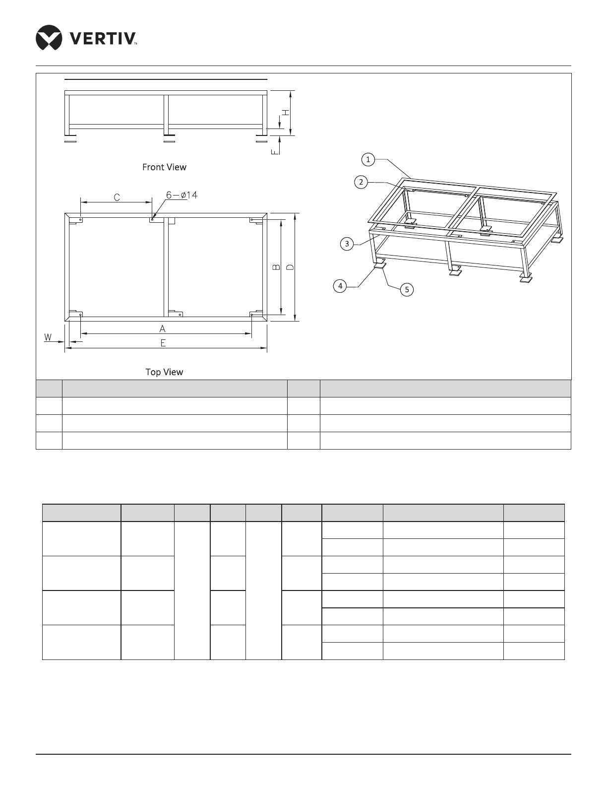
Vertiv | Liebert® PEX3™ Series Precision Air Conditioner | User Manual 37
Installation
No. Description No. Description
1 Upper rubber damping pad (5 mm thick) 4 Bottom plate (100 mm x 100 mm x 5 mm, 6PCS)
2 Fixed steel plate (3 mm thick 6PCS) 5 Bottom rubber cushion (10 mm thick, 6PCS)
3 Angle steel (3 mm thick)
Figure 2-23 Floor Stand of the Double Unit
Table 2-6 Floor Stand Dimensions (inch/mm)
Model A B C D E F H W
P1030 ~ P1040
25.6”/
650
33.9”/
860
/
38.6”/
980
36.6”/
930
/ 15.7”/400 <H≤21.6”/550 1.6”/40
F≤9.4”/240 21.7”/550 <H≤43.3”/1100 2.0”/50
P1050
33.5”/
850
/
44.5”/
1130
/ 15.7”/400 <H≤21.6”/550 1.6”/40
F≤9.4”/240 21.7”/550 <H≤43.3”/1100 2.0”/50
P2060 ~ P2080
61.0”/
1550
25.6”/
650
72.0”/
1830
/ 15.7”/400 <H≤21.6”/550 1.6”/40
F≤9.4”/240 21.7”/550 <H≤43.3”/1100 2.0”/50
P2090 ~ P2100
76.8”/
1950
33.5”/
850
87.8”/
2230
/ 15.7”/400 <H≤21.6”/550 1.6”/40
F≤9.4”/240 21.7”/550 <H≤43.3”/1100 2.0”/50
Page 49
Vertiv | Liebert® PEX3™ Series Precision Air Conditioner | User Manual 38
Installation
2.3.7. Installing Floor Stand
Determine the installation position according to the space requirements of the unit, and x the oor stand
onto the selected mounting position. The oor stand is xed to the ground using expansion bolts or spot
welding, and the alignment of the oor stand is calibrated by a horizontal ruler before it is xed. Ensure that the
top surface of oor stand is at uniform level. While designing and installing the downow unit which requires
lowering of EC fan, we must consider the proper gap distance and the base strength of the oor stand.
• Refer to Table 2-6 A/B/C as the center of the base from the mounting hole D/ E is the size of the base
frame.
• H is the height of the base, F is the height of the welding beam.
• W is the width of the angle, height ≤ 550 mm recommended use size 40 mm x 40 mm x 3 mm, the height
of > 550 mm quadrangular column is recommended to use 50 mm x 50 mm x 4 mm specication. The
bottom plate is recommended to use 100 mm x 100 mm x 5 mm.
• For the downow unit, the base must be greater than the height of 400 mm.
• For the upow unit, the base height must be about 200 mm.
• The side panels are suspended to the frame of the unit, ensure that oor stand should bear the weight of
the panels.
• The distance between the obstacles that may obstruct the air supply around the upper edge of the base
and the outer edge of the EC fan shall be greater than 160 mm.
Vibration Absorption Treatment
Place a layer of rubber cushion on the top, side of the base and on the bottom of the steel plate respectively to
prevent transmission of vibration during operation of the unit. Refer Table 2-7 for more details.
Table 2-7 Dimensions of Rubber Cushion for Vibration Absorbing
Item Specication
Rubber
cushion
Top Thickness: 3 mm to 5 mm
Lateral Thickness: 2 mm to 3 mm
Bottom Thickness: 10 mm to 12 mm
2.3.8. Installation of Indoor Unit
The indoor unit should be installed on the horizontal base plate, and ensure that all indoor units are at the same
level. The indoor unit and the horizontal base do not require any welding or other xed rigid connections.
Page 50
Vertiv | Liebert® PEX3™ Series Precision Air Conditioner | User Manual 39
Installation
2.3.9. Pipe Installation Unit (Air-cooled Units)
There are four kinds of pipe to be joint as follows:
• Condensed drain piping connection of the indoor unit
• Humidier inlet pipe connection
• Connection of the copper pipe (discharge and liquid pipe) between the indoor and outdoor unit.
• Long piping kit.
The following points need to be taken into consideration during the piping process:
• All the joints of the refrigerating pipes must be silver-brazed.
• The selection, layout, and xing of the pipes should comply to the industry standards and norms.
• Vacuum pumping and refrigerant charging operations, and procedures must comply with the industry
standards.
• Pressure drop, compressor oil return, noise, and vibration must be considered during the designing and
installation process.
Condensed Drain Piping Connection of Indoor Unit
The condensate of Infrared humidier and evaporator are connected by a cross connector and drained through
the drain pipe, as shown in Figure 2-24 The pipe outer diameter is 25 mm. If the drain pipe is used by three or
more units, the minimal pipe outer diameter should be 40 mm.
When connecting the drain pipe, ensure that the U bend is installed vertically and the ‘U’ shape is not
distorted, so that the condensate can be drained immediately and eectively.
Because the Infrared humidier contains hot owing water, the water pipe must be resistant to heat higher
than 90 °C.
Page 51
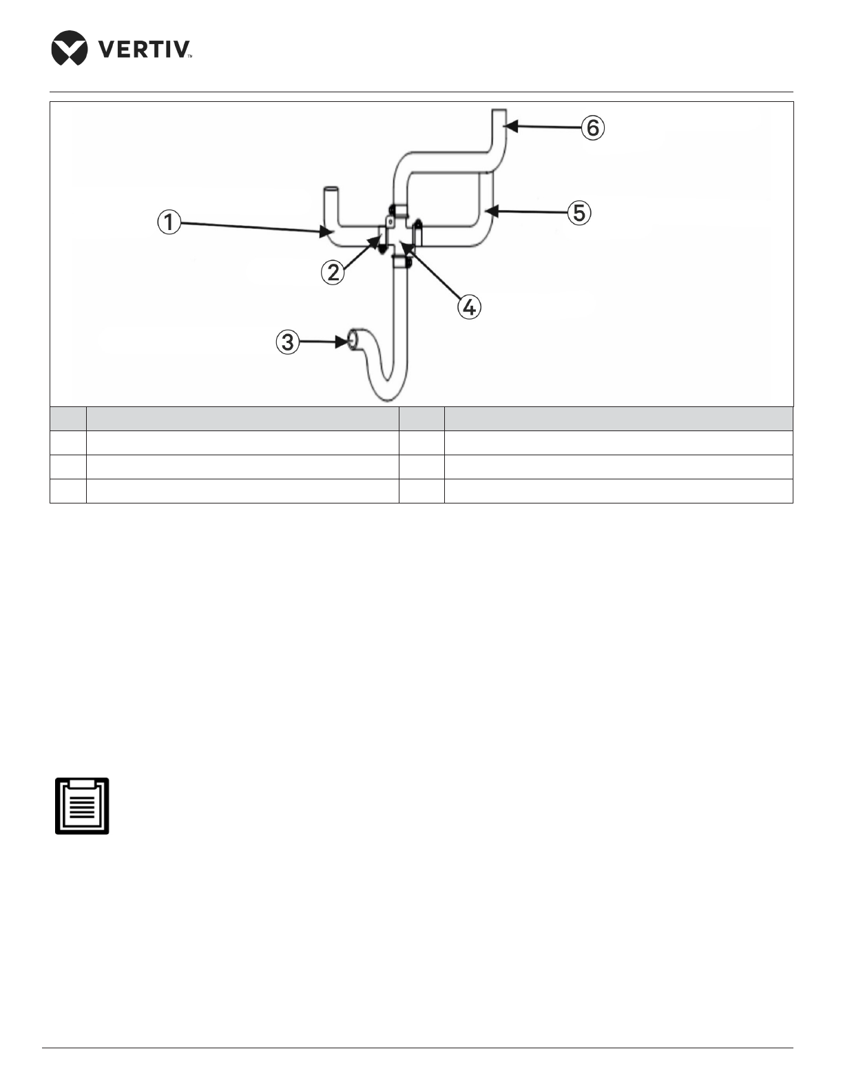
Vertiv | Liebert® PEX3™ Series Precision Air Conditioner | User Manual 40
Installation
No. Description No. Description
1 From evaporated condensed water pan 4 Cross connector
2 Hose clamp 5 From evaporated condensed water pan
3 To condensate drain pipe 6 From infrared humidier water pan
Figure 2-24 Connection of the Drain Pipe of Condensate Water
2.3.10. Infrared Humidication Inlet Pipe Connection
Requirements for connecting the water inlet pipe of infrared humidier:
• To facilitate maintenance, an isolation valve should be tted to the water inlet pipe.
• Ensure that the water inlet pipe is sealed properly to prevent leakage. The Infrared humidier reserved a 1/4”
copper nut and the 1/4” × 1/2” conversion copper thread connector to avoid loose connection as shown in
Figure 2-25 for air-cooled and water-cooled units.
• Where the main line pressure may exceed 700 kPa (the main line pressure range should be
100 kPa to 700 kPa), a pressure reducer should be installed.
• Where the pressure of the main pipe is lower than 100 kPa, there should be a water collecting tank and a
water pump system.
Page 52
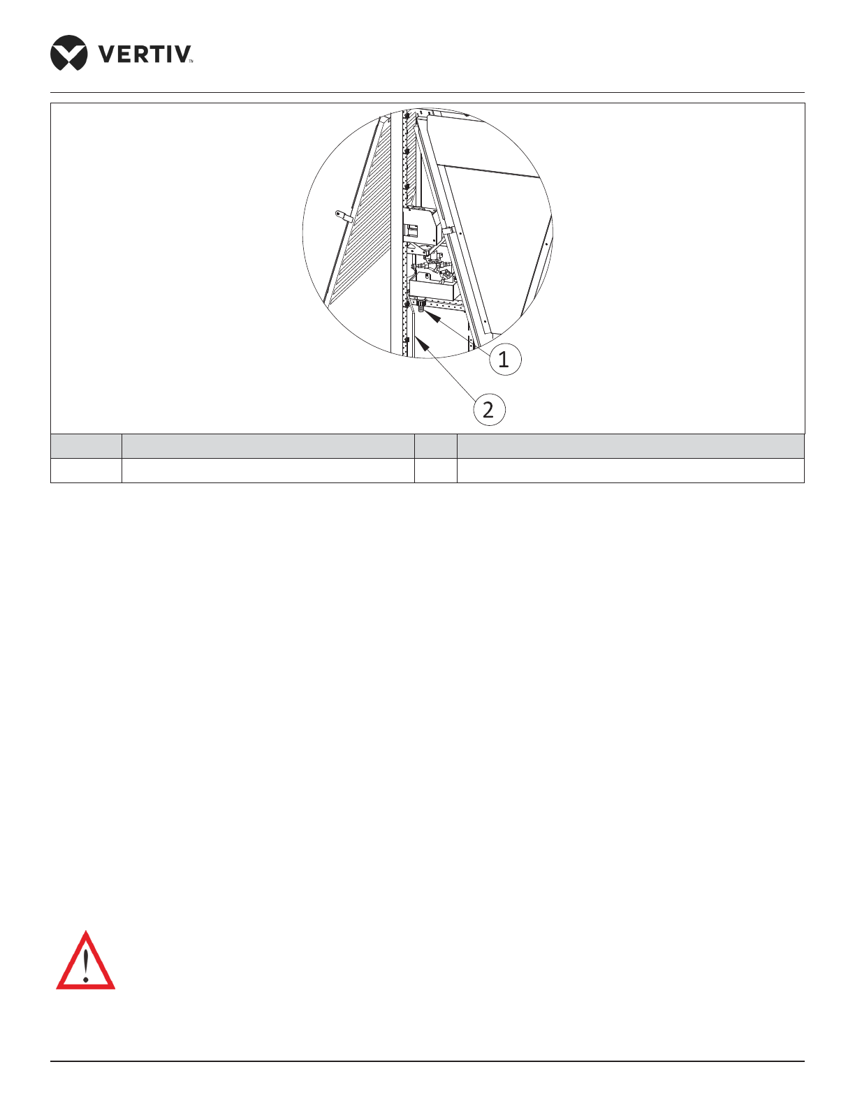
Vertiv | Liebert® PEX3™ Series Precision Air Conditioner | User Manual 41
Installation
No. Description No. Description
1 Outlet joints 2 Inlet pipe
Figure 2-25 Water Inlet Pipe of Infrared Humidifier
2.3.11. Connection of Copper Pipe (Discharge and Liquid pipe) between Indoor and
Outdoor Unit
• Select the appropriate dimension (Pipe diameter & Wall thickness) of pipes connecting the indoor and the
outdoor unit. Considering the eect of the diameter and wall thickness of copper piping on the pressure
drop of the system, the pipe dimensions of the indoor and outdoor unit should be determined according to
the specications in Table 2-9 or consult Vertiv local representative. The recommended dimensions of piping
is given in Table 2-8.
• Connect the copper pipes in brazing mode. The connection ball valves of the discharge pipe and liquid pipe
of the indoor unit are shown in Figure 2-26. Notes and instruction labels are pasted onto the base and the
side panel close to the ball valve. Ensure that the ball valve must be wrapped with a wet cloth before brazing
to protect the label from burning.
• Connect the discharge pipe and liquid pipe of the indoor unit according to the instructions on the labels.
• Horizontal sections of the discharge pipe should be sloped down from the compressor with a slope of at
least 1:200 (5 mm down for each 1 m run). The discharge pipes should be insulated where they are routed in
the conditioned space (including under a raised oor).
The exposure time of system pipes must not exceed 15min. Longer exposure will lead to the
compressor refrigeration oil being aected by moisture, which can aect the life of the key components and
the system operation stability.
Page 53
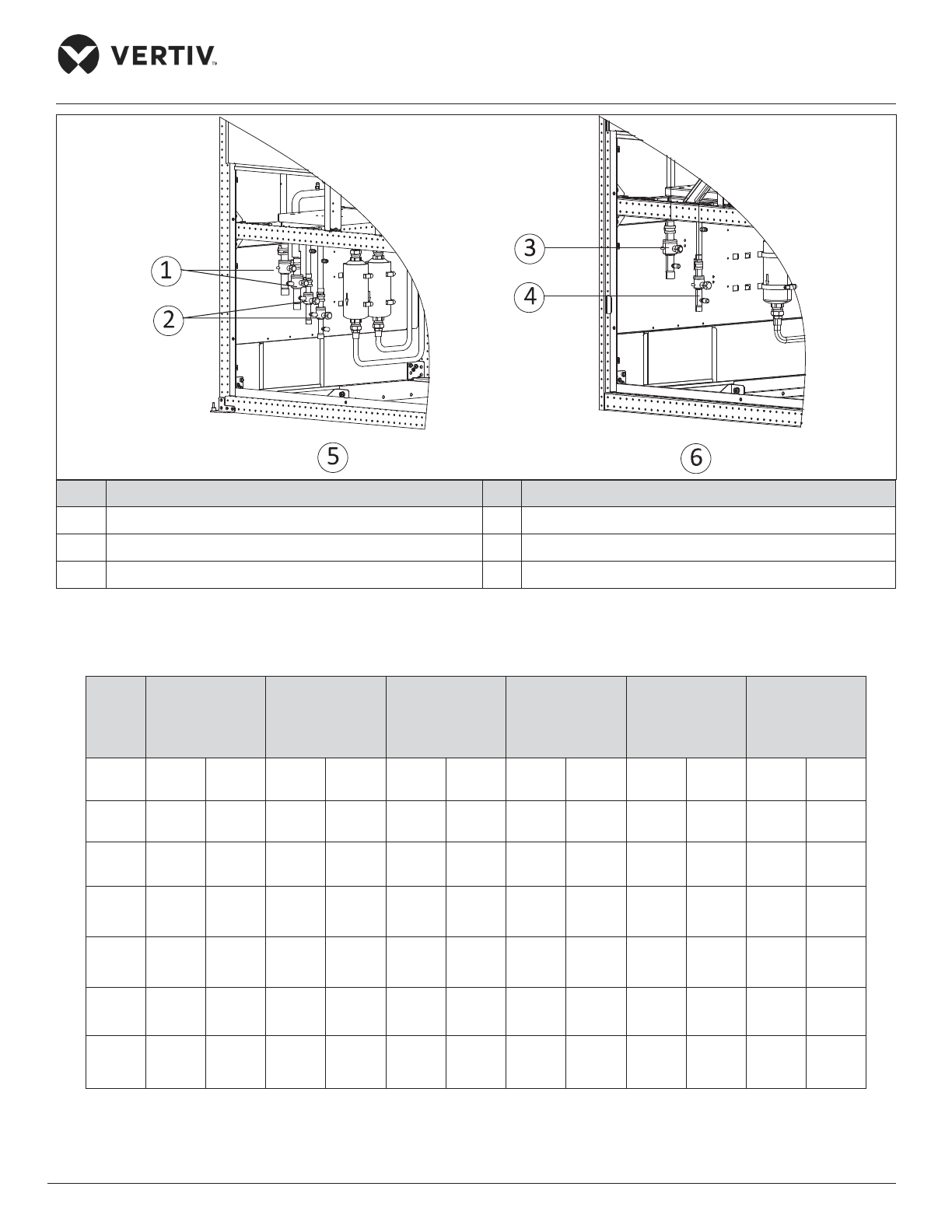
Vertiv | Liebert® PEX3™ Series Precision Air Conditioner | User Manual 42
Installation
No. Description No. Description
1 Discharge ball valve 4 Liquid pipe ball valve
2 Liquid pipe ball valve 5 Double circuit
3 Discharge ball valve 6 Single circuit
Figure 2-26 Locations of Discharge Pipe and Ball Valve and Liquid Pipe Ball Valve
Table 2-8 Recommended Pipe Size
Model
P1030
(single system)
P2060
(dual system)
P1040
(single system)
P2080
(dual system)
P1050
(single system)
P2100
(dual system)
P1050
(dual system)
P2070
(dual system)
P2090
(dual system)
Pipe
Length
D L D L D L D L D L D L
10m 16/16 16/16 19/19 16/16 19/19 19/19 16/16 16/16 19/19 16/16 19/19 19/19
20m 19/19 16/16 22/22 16/16 22/22 19/19 16/16 16/16 19/19 16/16 22/22 19/19
30m 19/19 16/16 22/22 16/16 25/22 19/19 19/16 16/16 22/19 16/16 22/22 19/19
40m 22/19 16/16 25/22 16/16 25/25 19/19 22/16 16/16 25/19 16/16 25/22 19/19
50m 22/19 16/16 25/22 16/16 25/25 19/19 25/16 16/16 25/19 16/16 25/22 19/19
60m 25/19 16/16 25/22 16/16 25/25 19/19 25/16 16/16 28/19 16/16 28/22 19/19
Page 54
Vertiv | Liebert® PEX3™ Series Precision Air Conditioner | User Manual 43
Installation
• D: Discharge line, L: Liquid line
• 22/ 19: horizontal pipe diameter is 22 mm, vertical pipe diameter is 19 mm
• If the pipe length exceeds 60 m or drops over 20 m, please consult Vertiv local representative for details.
• If the outdoor temperature is below -20 °C, use the low temperature kit and consult Vertiv local
representative for details.
Table 2-9 Pipe Wall Thickness Requirements
Pipe Dimensions Outer Diameter Wall Thickness (mm)
mm inch mm inch
16 5/8 ≥1 0.04”
19 >3/4 ≥1.2 0.05”
22 7/8 ≥1.2 0.05”
25 1 ≥1.5 0.06”
28 1-1/8 ≥1.5 0.06”
32 >1-1/4 ≥1.5 0.06”
35 1-3/8 ≥1.5 0.06”
2.3.12. Height Dierence Requirements and Equivalent Length Calculation
The long piping kit is the standard component for Liebert PEX3. Height dierence between the indoor
and outdoor unit is shown in Table 2-10. The equivalent length can be calculated by selecting appropriate
dimensions in accordance with the respective diameter, refer Table 2-11 for the equivalent length of the
sub-assembly.
Table 2-10 Height Distance between Indoor and Outdoor Unit
Relative Position Distance
Condenser above the indoor unit + 20 m
Condenser below the indoor unit -5 m
• If the vertical distance between indoor and outdoor unit exceeds the values in Table 2-10, consult
Vertiv local representative.
• ‘U’ trap should be installed for every 7.5 m of vertical distance consult Vertiv local representative for details.
Page 55
Vertiv | Liebert® PEX3™ Series Precision Air Conditioner | User Manual 44
Installation
Table 2-11 Equivalent Length of Each Sub-Assembly
Fluid Pipe Diameter
(inch)
Equivalent length (m)
Elbow 90° Elbow 45° T-piece
3/8 0.21 0.10 0.76
1/2 0.24 0.12 0.76
5/8 0.27 0.15 0.76
3/4 0.3 0.18 0.76
7/8 0.44 0.24 1.1
1-1/8 0.56 0.3 1.4
2.3.13. Pipe Installation Unit (Water-cooled unit)
There are three kinds of pipe to be joint as follow:
1. Condensed drain piping connection of the indoor unit (the same as the Air-cooled unit).
2. Humidier inlet pipe connection (the same as the Air-cooled unit).
3. Water inlet and outlet pipe of cooling water.
The following points need to be taken into consideration during the piping process:
• The selection, layout, and xing of the pipes should comply to the industry standards and norms
• Vacuum pumping and refrigerant charging operations, and procedures must comply with the industry
standards.
2.3.14. Connection between Water inlet and Outlet Pipe of Cooling Water
Each water cooled cooling system uses a BPHE and an MBV. The water supply (inlet) pipe and water return
(outlet) pipe of the cooling water should be connected to the system. A lter (Filter mesh: 1mm) and motorized
isolation valves should be mounted on the water supply (inlet) pipe of the cooling water, and this motorized
isolation valve acts as a balancing valve. The cooling water system with a balancing valve can control the water
distribution more accurately and it also enhances the eiciency of pump.
On the other hand, the motorized valve can keep the optimal condensing temperature by regulating the internal
water ow. The actuator of the regulating valve also features a manual override to allow water side balancing
by the installer. It is recommended to arrange the cooling water piping separately for dierent systems, so that
repairing one pipe will not aect the operation of the other piping.
Page 56
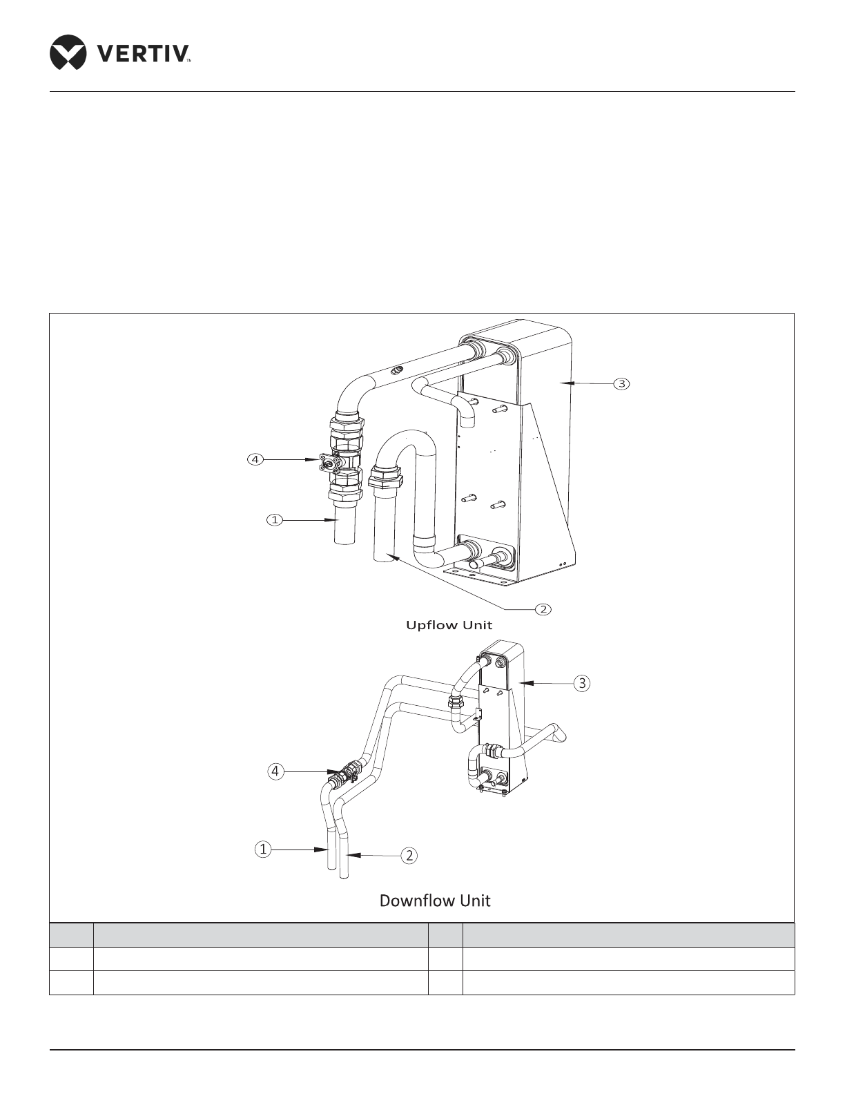
Vertiv | Liebert® PEX3™ Series Precision Air Conditioner | User Manual 45
Installation
The water pressure should be high enough to overcome the pressure drops created by all the components of
the water system. In addition, because of the sediments and impurities more pressure drop can occur after long
term operation, user should arrange a redundancy of 20% to 25% when selecting the pump. Inlet water pressure
of 0.1 MPa to 0.3 MPa is recommended, but the water ow of the system should be guaranteed.
Refer Figure 2-10 for the system arrangement of the water-cooled unit. The material used for the cooling water
inlet and outlet piping of the indoor unit is copper with outer diameter of 32 mm.
As shown in Figure 2-27 connect the pipes through direct brazing at the site and ensure that the junction is
well-sealed.
No. Description No. Description
1 Water outlet 3 BPHE
2 Water inlet 4 A lter with motorized ball valve
Figure 2-27 Unit Connection (Water-cooled)
Page 57

Vertiv | Liebert® PEX3™ Series Precision Air Conditioner | User Manual 46
Installation
2.3.15. Lowering the Fan
Before commissioning, the EC fans of the downow unit must be lowered. The downow unit is equipped with
a lowering tool when it is shipped. The lowering tool that uses winch is shown in Figure 2-28 for air-cooled and
water-cooled unit. It mainly includes, winch bracket, hook, sling, hand winch, handle, and a L-shaped lifting
component.
No. Description No. Description
1 Winch bracket 4 Handle
2 Hook 5 Sling
3 Winch
Figure 2-28 Fan Elevator Assembly (Winch mode)
• Lowering Procedure
1. Installing lift and lowering kit for fan: Open the unit maintenance cover, check the xing bolts (refer, total
two PCS) of the L-shaped lifting component to ensure that it is xed properly, and then install the xing bolts
(total four PCS) of the winch bracket, as shown in Figure 2-29.
Page 58
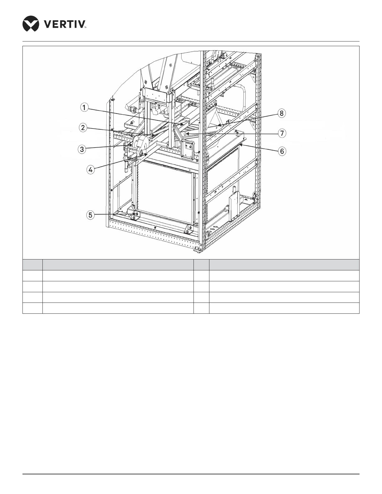
Vertiv | Liebert® PEX3™ Series Precision Air Conditioner | User Manual 47
Installation
No. Description No. Description
1 Winch bracket 5 Bolt
2 Lifting rope 6 Fan
3 Winch 7 Hoist hanging hole
4 Winch handle 8 Lifting fastener
Figure 2-29 Installed Winch Bracket
2. Turn the handle and use the winch hook to hook the L-shaped lifting component to the middle round hole
(refer Figure 2-30). Adjust the handle until the sling is completely tight.
3. Cut the cable tie that binds the fan cables to ensure that the cable length meets the fan lowering
requirements, and then remove the xing bolts (refer Figure 2-30, total four PCS) for fan lowering.
4. Hold the winch handle rmly, and then turn the handle counterclockwise to lower the fan. The status after
the fan has been lowered is shown in Figure 2-31.
Page 59
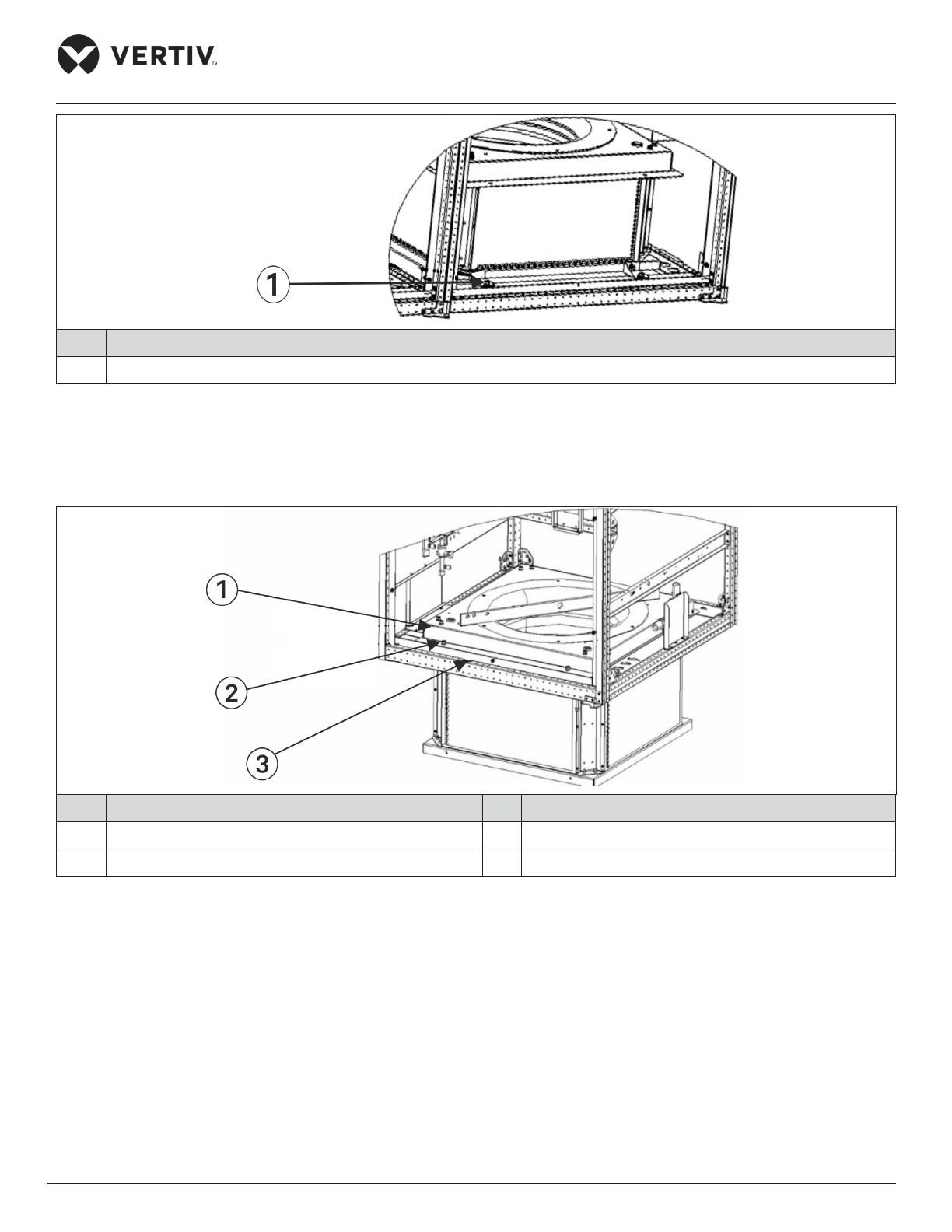
Vertiv | Liebert® PEX3™ Series Precision Air Conditioner | User Manual 48
Installation
No. Description
1 Bolt
Figure 2-30 Position of Fixing Bolt
5. Install the xing bolts, as shown in Figure 2-30 and hold the arrangement tight during operation with total
four PCS of bolts.
No. Description No. Description
1 Fan mounted roof 3 The unit bottom
2 Bolt
Figure 2-31 Lowered Fan
6. Remove the hook from the L-shaped lifting component, turn the handle clockwise, arranged the sling in
order and remove the xing bolts (refer Figure 2-30: Position of Fixing Bolt, totally two PCS) of the winch
bracket, and take out the winch and the bracket assembly.
7. Remove the xing bolts of the L-shaped lifting component and take out the L-shaped lifting component. At
this point, the operation of lowering the fan of the one-bay unit is complete. For the unit with two fans, lower
the other fan too, using the fan elevator assembly. The requirements are as follows:
8. Repeat steps 1-7 of the one-bay unit to lower the other fan.
9. After lowering all fans, arrange the fan cables in the correct order and x them using a cable tie.
Page 60
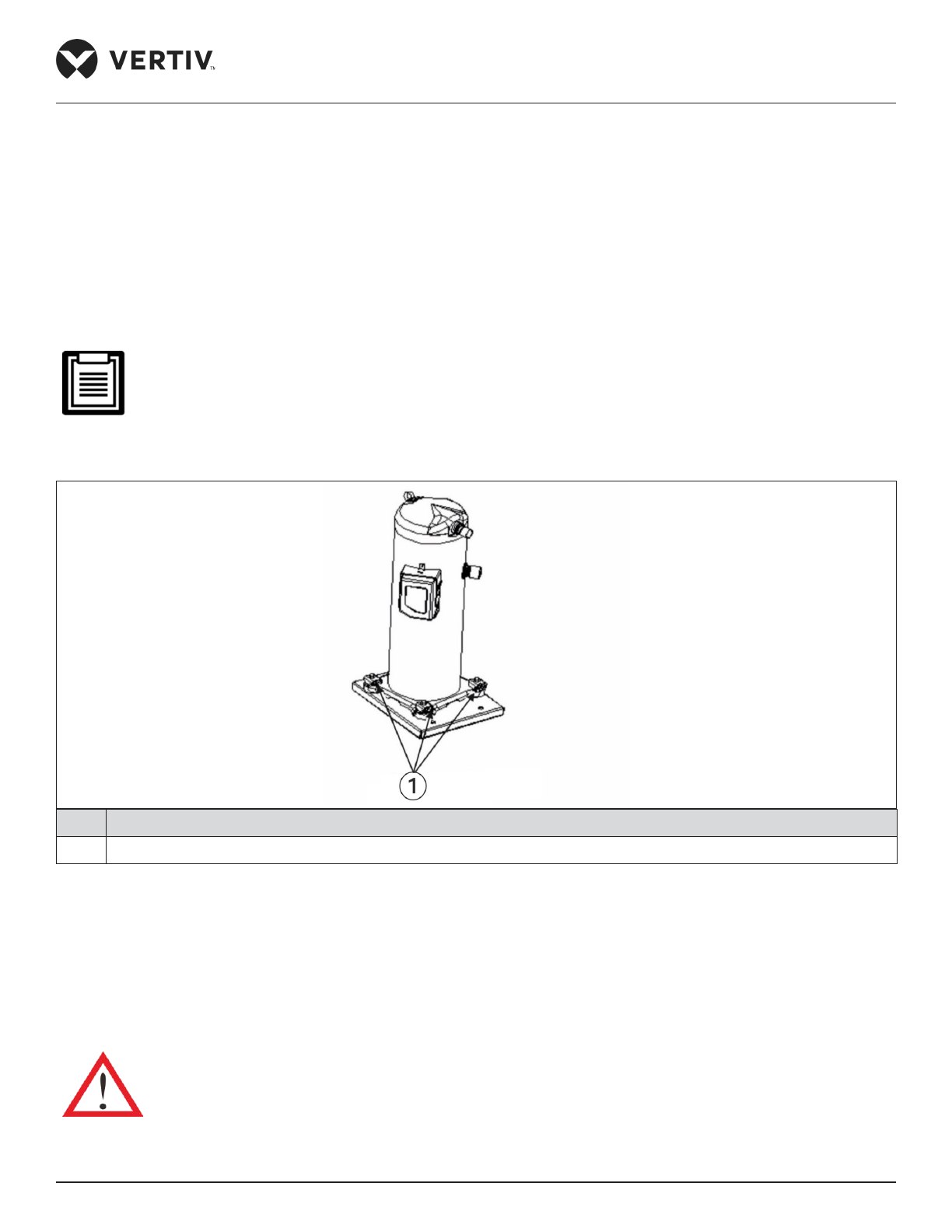
Vertiv | Liebert® PEX3™ Series Precision Air Conditioner | User Manual 49
Installation
10. Conrm whether the EC fan has been lowered and installed and ensure that the blade does not touch the
fan housing when the fan rotates.
2.3.16. Removing Transportation Fixing Plate of the Compressor
Damping cushions are added to the compressor base to reduce the vibration and noise during operation.
However, such method cannot best withstand the vibration while transporting the unit and may result in
loosening connections and wearing of certain parts. Hence to ensure the rigidity of the compressor during
transportation, three L-shaped xing plates are added to the compressor base.
• Remove the three L-shaped xing plates after installation, and then restore the bolts and washers in
reverse sequence of the disassembly process.
• The fastening torque of the bolts is (12±1) Nm.
No. Description
1 Fixed sheet metal (total 3PCS)
Figure 2-32 Position of “L” Shape Fixing Plate
2.3.17. Removing of Fasteners of Infrared Humidier
The oating pole of the humidier high water-level switch is tightly bound together with a rubber string before
delivery, as shown in Figure 2-33. Remove the rubber string before the unit operation. Otherwise, the unit will
not be able to detect the high water-level alarm.
Do not touch the lamps with the bare hands.
Page 61
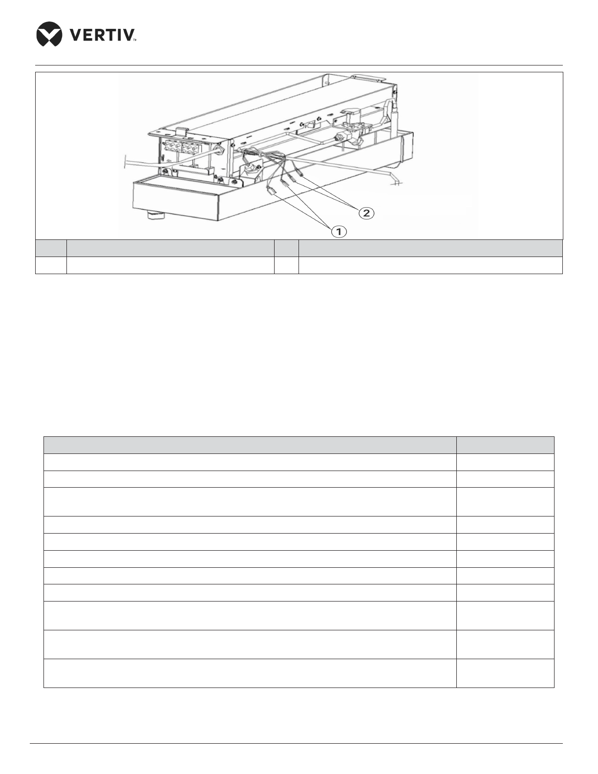
Vertiv | Liebert® PEX3™ Series Precision Air Conditioner | User Manual 50
Installation
No. Description No. Description
1 Plug terminal 2 Connect HWA plug terminal to water level switch
Figure 2-33 High Water Level Detection Float Switch Lever and Terminal HWA
2.3.18. Removing Pipe Fasteners
To prevent the long copper pipes from scratching the metal plate and being damaged, the pipes are cushioned
with foam or bound before delivery. Remove those materials before power-on commissioning.
2.3.19. Installation Inspection
Table 2-12 Installation Inspection Checklist
Check Items Results
Leave enough space around the unit for maintenance
The equipment is installed vertically, and the installation fasteners have been xed
The pipes between the indoor and outdoor unit have been connected, and the ball valves of
the indoor and outdoor unit have been fully opened
Condensate pump is installed (if required)
The drain pipe has been connected
The water supply pipe for the Infrared humidier has been connected
All pipe joints are tightened
Fasteners for transportation have been removed
Irrelevant things (such as transportation material, structure material, and tools) inside or
around the equipment have been cleared after the equipment is installed
The airow distribution system has been installed in each room
(e.g. raised oor/grill, duct, etc.)
The upow unit must have plenum or air duct connection, and after installation the fan and
heater shall not be accessible
Everything is checked and veried, follow the electrical installation.
Page 62

Vertiv | Liebert® PEX3™ Series Precision Air Conditioner | User Manual 51
Installation
2.4. Electrical Installation
In this section, the electrical installation of the PEX3 unit is explained in-depth to help to get familiar with the
various tasks such as the installation considerations, indoor wiring, power lines connection to the condenser,
and the checklist.
2.4.1. Installation Precautions
• The connection of all power cables, control cables, and ground cables should comply with the local and
national electrical regulations.
• The electrical installation and maintenance must be performed by authorized professional/installation
personnel.
• See the unit name-plate for the full load current. The cable sizes should meet the local wiring rules.
• Mains supply requirement: 400 V, 3 Ph +N~50 Hz.
• If the soft power cable uses Y-connection, and if the cable is damaged, it must be replaced by professional
service personnel.
• Before the wiring, use a volt-meter to measure the power supply voltage and ensure that the power supply
has been switched o.
• The applicable grid for this air conditioner, TN, TT star connection power system; consult Vertiv local
representative for other connections.
• A breaking device must be provided to disconnect the unit from power supply.
• The short circuit breaking current of the unit is 6 kA.
• Install suitable RCD according to actual installation.
2.4.2. Wiring of Indoor Unit
The locations of the low voltage devices are visible after opening the front door of the electrical control box of
the indoor unit, as shown in Figure 2-34 ( for air-cooled/ water-cooled model). The distribution information of
the detailed low voltage components are dierentiated according to the labels.
Page 63
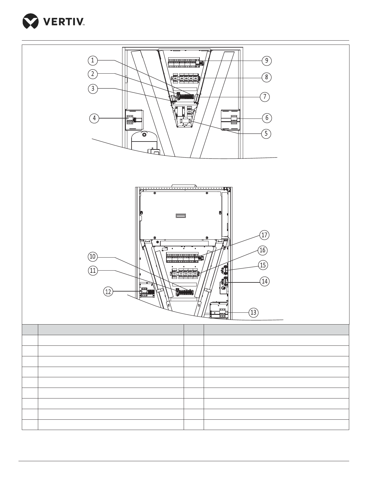
Vertiv | Liebert® PEX3™ Series Precision Air Conditioner | User Manual 52
Installation
No. Description No. Description
1 Terminal row 10 Terminal row
2 Electrical row 11 Electrical relay
3 Dierential pressure switch 12 Outdoor machine empty open (Only for Air-cooled)
4 Outdoor machine empty open (Only for Air-cooled) 13 Power connector
5 Transformer 14 Dierential pressure switch
6 Power connector 15 Airow loss switch
7 Airow loss switch 16 Contact device
8 Contact device 17 Bus/ air open
9 Bus/ air open
Figure 2-34 Electrical Control Box
Page 64
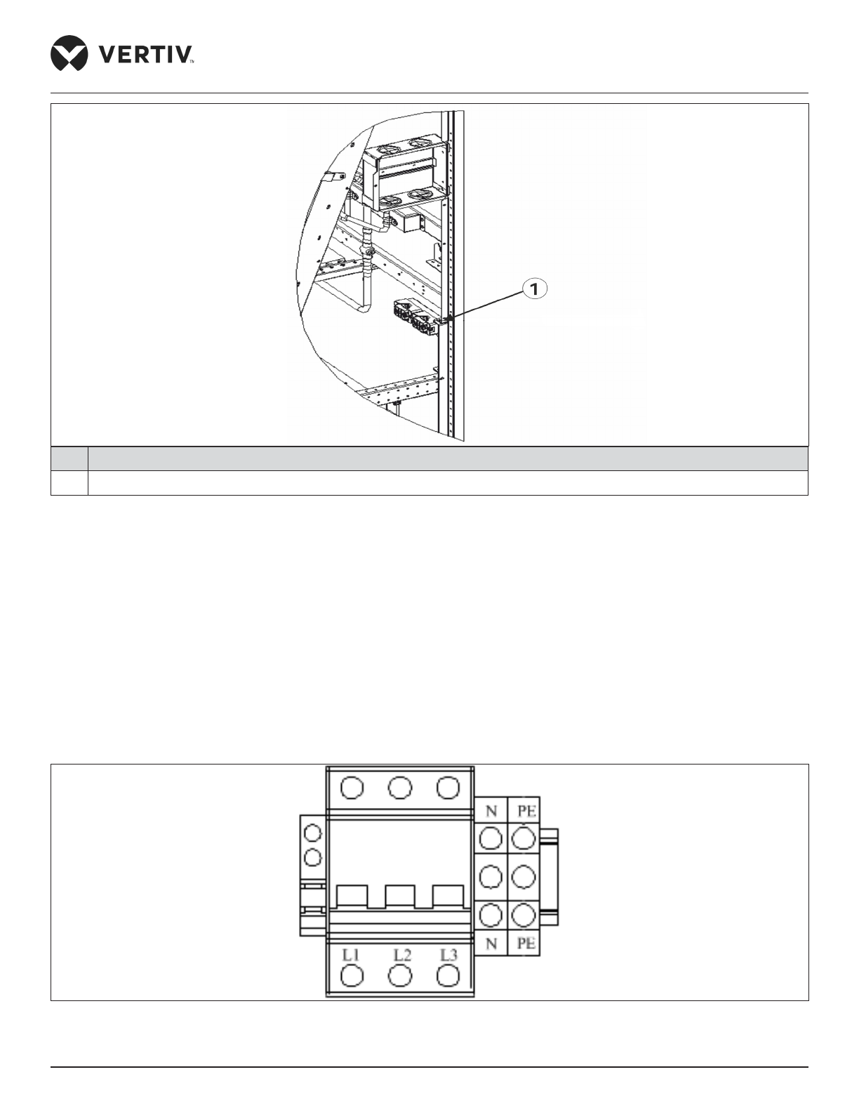
Vertiv | Liebert® PEX3™ Series Precision Air Conditioner | User Manual 53
Installation
No. Description
1 Cable clamp
Figure 2-35 Cable Clamp Position
Figure 2-34 shows the details of power connectors in electrical control box, connects terminals L1 ~ L3, N, and
PE respectively to their counterparts of external power supply. Reserve some redundancy of the incoming cable
and x the cable to the cable clamp located on the inner side panel of the unit, refer Figure 2-35. The types of
wiring cables are of copper conductor, and the cross-section-area requirements of the copper wires can vary
with the dierent models. For the cable specication, refer the rated Full Load Ampere (FLA) in the
Table 2-13. Over-current/ Ground fault protection device is recommended to use the air switch with the feature
of D-release. Refer Table 2-14 for specic model selection.
An enlarged view of outdoor unit MCB (only for Air-cooled) and eld terminal array are shown in Figure 2-37.
L1~L3, N and PE are respectively connected with the corresponding end of the outdoor unit power line.
Figure 2-36 Enlarged View of Power Connector
Page 65
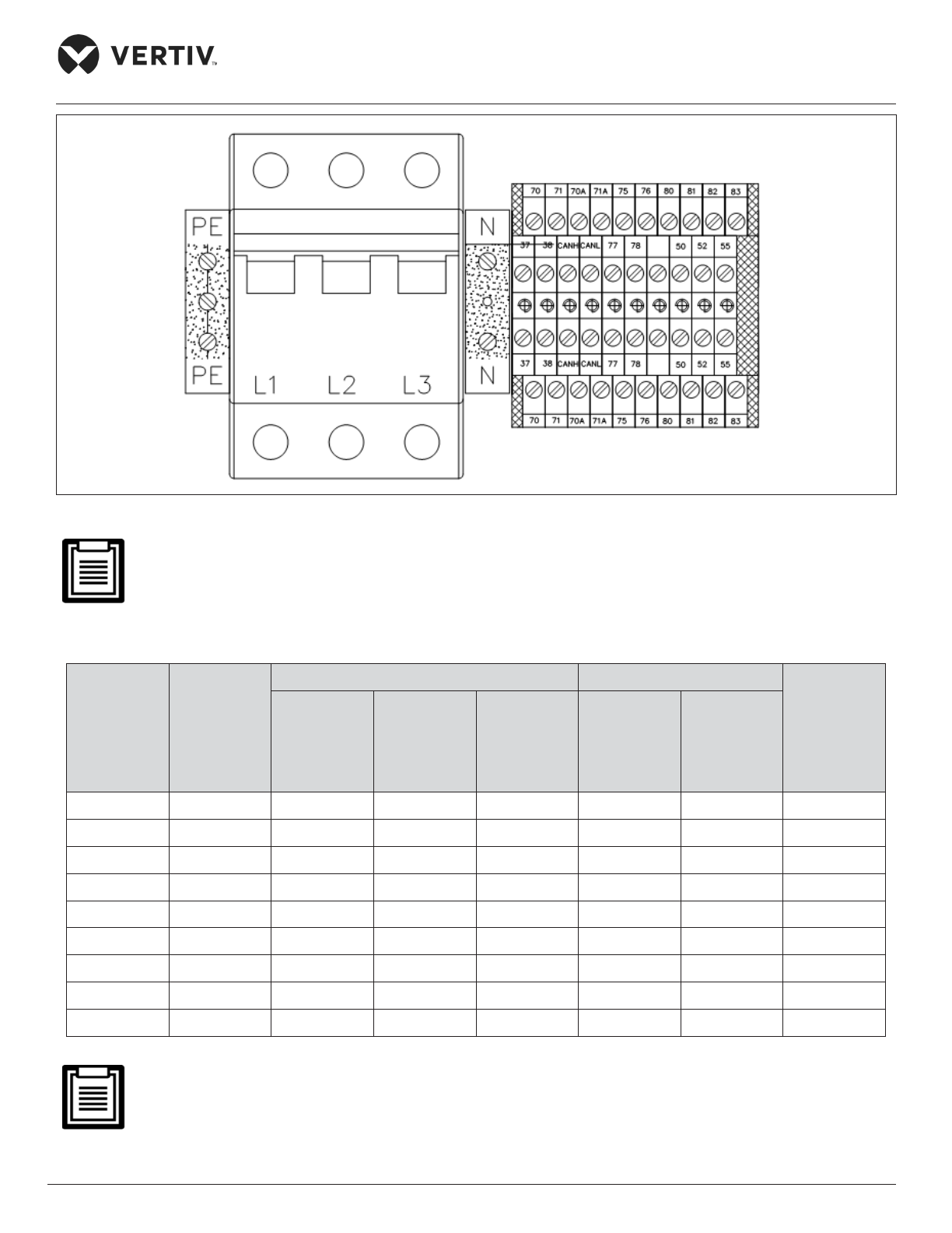
Vertiv | Liebert® PEX3™ Series Precision Air Conditioner | User Manual 54
Installation
Figure 2-37 Enlarged View of Condenser MCB and Terminal
The cable sizes should meet the local wiring regulations.
Table 2-13 Rated Full Load Ampere (FLA)
Unit Type
Standard
Models
Electrical Heating No Electrical Heating
Cross-
Section-
Area of
Copper Wire
mm
2
Standard
Model with
2-stage
Electrical
Heating
1-stage
Electrical
Heating/
No
Humidier
2-stage
Electrical
Heating/
No
Humidier
With
Humidier
Without
Humidier
P1030 29.6 38.7 29.6 38.7 26.6 20.5 7
P1040 37.8 51.5 37.8 51.5 30.2 24.1 10
P1050 (S) 46.4 60.1 46.4 60.1 38.8 32.7 12
P1050 (D) 46.8 60.5 46.8 60.5 39.2 33.1 12
P2060 54.7 68.4 54.7 68.4 52.4 41.0 14
P2070 57.7 71.4 57.7 71.4 55.4 44.0 14
P2080 66.4 84.7 66.4 84.7 59.6 48.2 17
P2090 76.4 94.7 76.4 94.7 69.6 58.2 19
P2100 83.6 101.9 83.6 101.9 76.8 65.4 21
• The standard model is congured with compressor, EC fan, humidier and one-stage electrical heating.
• Air-cooled unit FLA excludes the outdoor unit current.
Page 66
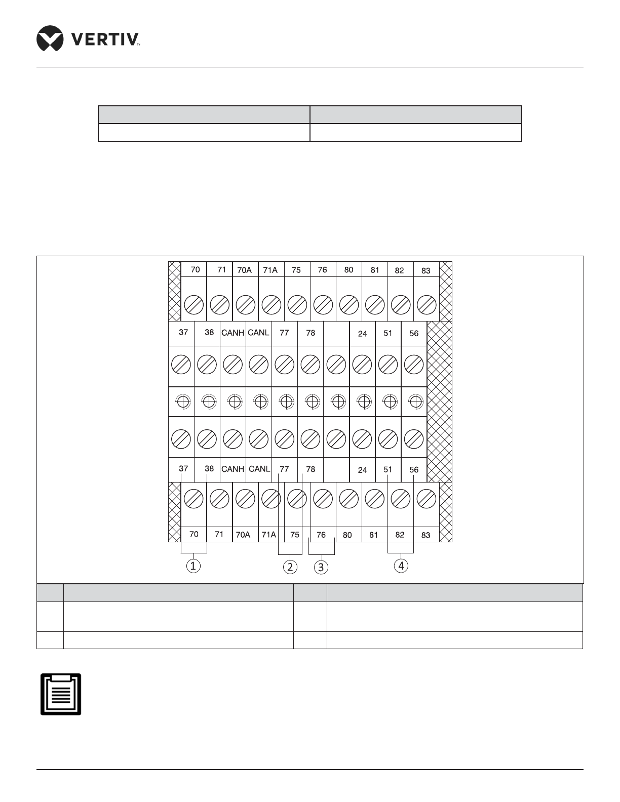
Vertiv | Liebert® PEX3™ Series Precision Air Conditioner | User Manual 55
Installation
Table 2-14 Rated Current of MCB
Type Rated Current of MCB (A)
P1030~P2100 125
2.4.3. Connecting Control Cables
The position of eld connection terminals is shown in Figure 2-36 and the enlarged view of the terminal row is
shown in Figure 2-38. The upper part of the terminal row is connected with the unit, and the lower part is the
interface of the user control signal line.
No. Description No. Description
1 37/38 short connection, remove this short wire at
remote shutdown
3 Access to public alarm
2 Rs485 interface 4 Custom alarm end for its common end
Figure 2-38 Enlarged View of Terminal Block/Row
Before connecting the control line, it is mandatory to perform the corresponding anti-static measures..
Page 67

Vertiv | Liebert® PEX3™ Series Precision Air Conditioner | User Manual 56
Installation
2.4.4. Connecting Water-Under-Floor Sensor
Each unit is equipped with a water-under-oor sensor. Connect one end of the sensor to terminal 51# and the
other end to the common terminal 24#. The number of sensors in parallel connection is not limited, but each
unit has only one water-under-oor alarm.
2.4.5. Remote Shutdown Control Line Connection
As shown in Figure 2-38, 37# and 38# terminals can connect to remote shutdown switch, and they have been
shorted in the factory and the shorting cable should be removed if the terminals are to be connected to the
remote shutdown switch.
When 37# and 38# are opened, the unit will shut down.
2.4.6. Customized Alarm Terminal
Terminals 51# and 56# can be connected to two types of sensors, and terminal 24# is their common terminal
and can be dened as water-under-oor sensor. If there is an optional smoke detector, the alarm can be
involved in any between #56 and # 24 terminal. After the customer terminals are connected to external alarm
signals, the corresponding customized alarm should be set through the controller.
When the contact is open, and no external alarm is generated, the input state of the customer terminal is open.
But when the contact is closed, and the external alarm is generated, the input state of the customer terminal
will be shorted. At this point, the Precision Air Conditioner system will generate an audible alarm, and the
controller LCD will display the alarm information.
• LCD displays the corresponding alarm content
• Terminals 37# and 38#: Remote alarm
• Terminals 51# and 24#: Water-under-oor sensor by factory settings
2.4.7. External General Alarm
Terminals 75# and 76# can be connected to the external general alarms. The output signals to external alarm
devices, such as alarm indicator. When critical alarm occurs, the contact will be closed to trigger remote alarms,
send signals to the building management system or dial the paging system automatically. The power supply of
the external general alarm system is user prepared.
Page 68

Vertiv | Liebert® PEX3™ Series Precision Air Conditioner | User Manual 57
Installation
2.4.8. Condenser Wiring
• Condenser Control Signal Terminal
70#/ 71# and 70A#/ 71A# are control signal input terminals for two circuits of condensers and their switching
status are identical with those of the compressor.
• Control Signal Line Connected to the Condenser
Open the sealed panel of the electric control box of the condenser to reveal the fan speed controller board,
according to the cable connection instructions in the “Liebert Condenser User Manual”. The signal cable
connection of condenser is as follows.
• Wiring Mode of PEX Condenser of Single System Unit Matches with Indoor Unit of Single System
The digital signal of dry contact J6 on the board (Refer Cable terminals section in “Vertiv PEX+ Condenser User
Manual” for the locations) is connected to the control terminals 70#/ 71# of the indoor unit.
• Wiring Mode of two PEX Condensers of Single System Unit Matches with Indoor unit of Dual System
The digital signals of dry contacts J6 on the condenser board corresponding to compressor 1# are connected
to the control terminals 70#/ 71# of the indoor unit, and the digital signals of dry contacts J6 on the condenser
board corresponding to compressor 2# are connected to the control terminals 70A#/ 71A# of the indoor unit.
• Wiring Mode of PEX Condenser of Dual System Unit Matches with Indoor unit of Dual System
Short-connected the terminals 70# & 70A# and 71# & 71A#. The digital signal of dry contact J6 on the board
can be connected to the control terminals 70#/ 71# or 70A#/ 71A#.
• Wiring Mode of LVC Condenser matches with two Indoor units of single system
Compressor single terminal row 70#/ 71# in 1# condenser electrical control box (refer “the LVC Condenser
Series User Manual” for external cables) can be introduced from either control interface of indoor unit.
Compressor single terminal row 70/ 70A#/ 71/ 71A# in 2# condenser (refer “the LVC Condenser Series User
Manual” for external cables) can be introduced from another 70#/ 71# control interface of indoor unit.
• Wiring Mode of LVC Condenser matches with Indoor unit of dual system
The power cables of condenser are connected with the MCBs (Figure 2-37) reserved in the indoor unit.
Page 69

Vertiv | Liebert® PEX3™ Series Precision Air Conditioner | User Manual 58
Installation
2.4.9. Check the Installation
After completion of the electrical installation, should check conrmation as per Table 2-15.
Table 2-15 Inspection Checklist
Check items Results
The power supply voltage meets the rated voltage on the unit name plate
The system electric loop has no open circuit or short circuit
Power cables and ground cables to the MCBs, indoor unit and condenser
are well connected
The ratings of the MCBs and fuses are correct
The control cables are well connected
All the cables connections are fastened, with no loose screws
Do not power-on the unit, unless the unit has been checked and conrmed by Vertiv Personnel/ Vertiv
Service Team.
Page 70
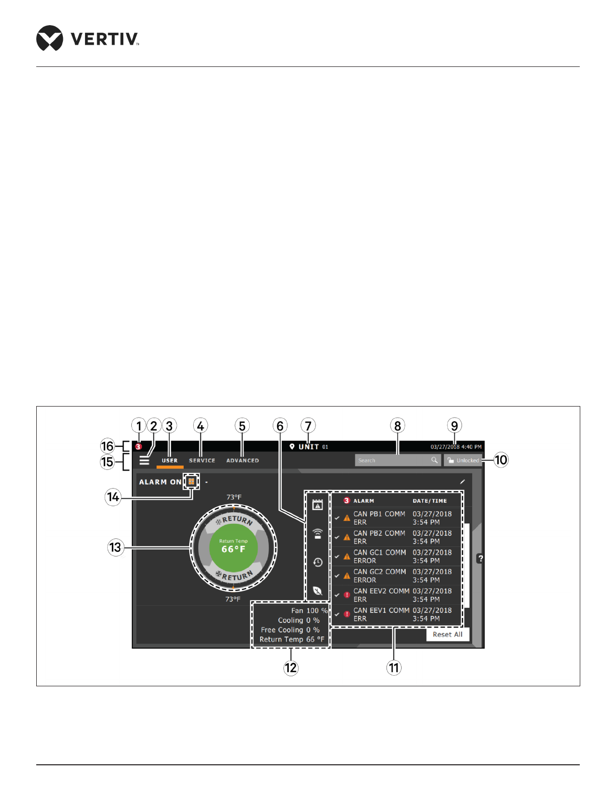
Vertiv | Liebert® PEX3™ Series Precision Air Conditioner | User Manual 59
Touchscreen Operation
Chapter 3: Touchscreen Operation
The Liebert iCOM oers the highest capability for unit control, communication, and monitoring of Liebert
Thermal Management Units. It is available as factory-installed on new units and assemblies.
3.1. Touchscreen Display and User Interface
The Liebert iCOM touchscreen, user interface speed set up, installation, and simplied control of Liebert PEX3
units literally putting cooling-system monitoring and management at your ngertips.
• User and service menus are password-protected to prevent unauthorized changes in the cooling unit
operation settings.
• The touchscreen is back-lit and auto-dims after a period of non-use, then turns o. Touch the screen to
re-illuminate the main screen.
• iCOM ships with default settings for eicient and eective operation of most cooling-units and it is easily
congured to meet any requirement.
• iCOM menus and displays are based on the options installed on the cooling units that it monitors and
manages.
Figure 3-1 iCOM Main Display
Page 71
Vertiv | Liebert® PEX3™ Series Precision Air Conditioner | User Manual 60
Touchscreen Operation
Table 3-1 Main Display Controls and Options
No. Description
1 Alarms present: Displays the number of active alarms.
2
Menu icon: When unlocked, displays a menu for user or service option depending on which icon is
selected.
3
User icon: When selected the user options are available on the main display and menu
(Note: Unlock the display with the user Password to access the menu and options. See “Powering-On iCOM and
Logging-in/ Unlocking Controls”).
4
Service icon: When selected the service options are available on the main display and menu
(Note: Unlock the display with the user Password to access the menu and options. See “Powering-On iCOM and
Logging-in/ Unlocking Controls”).
5
Advanced icon: When selected the advanced options are available on the main display and menu
(NOTE: Unlock the display with the Service Password to access the menu and read-only options. See “Powering-
On iCOM and Logging-in/ Unlocking Controls”.
6
Cooling-unit parameters: Status display of selected system parameter settings. See Adding and
Adjusting Content.
7 Unit Identication: You can customize the unit name up to 6 characters/ numbers.
8 Search icon: Open the keyboard to search for controls and setting locations. See “Searching”.
9 Date/ Time.
10
• Lock/Unlock icon: Indicates whether or not the user and service is logged-in and options are
accessible
• Locked icon = display is read only
• Unlocked icon = User or service is logged-in and option is accessible
• See Powering-on iCOM and logging-in/ Unlocking Controls
11
Secondary-content panel: When accessing setting/conguration via the menus, the settings is
displayed in the right, ‘Secondary’ panel
12
Summary of current unit function. You can customize to show fan speed, cooling, percentages from
any installed device, and any physical (sensor) values.
13 Status Dial: Circular display of setpoints and environment conditions of the unit. See Touchscreen
14
Teamwork-mode icon: In a panel with status content the Teamwork Mode icon indicates the mode
selected
15 Control header: Control to access the user and service menus. See Control Header
16 Status Header. Displays the alarm status, unit identication, and the current date and time.
Page 72
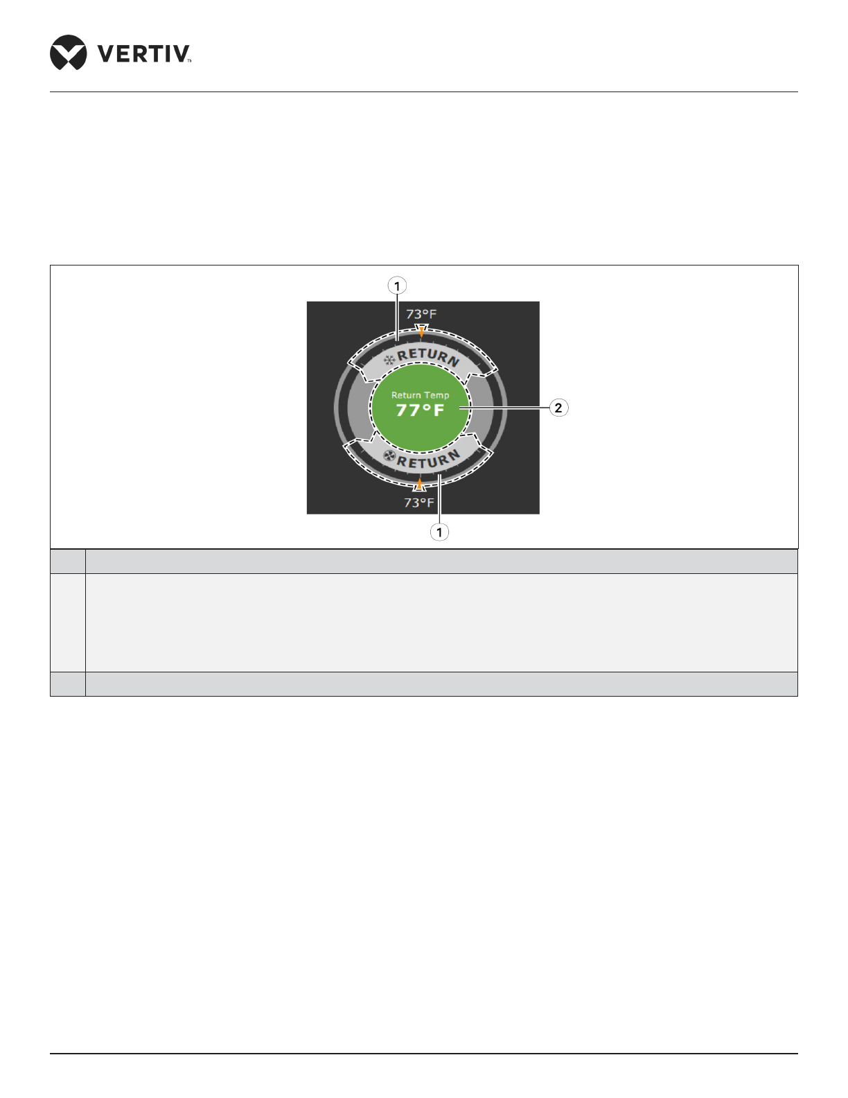
Vertiv | Liebert® PEX3™ Series Precision Air Conditioner | User Manual 61
Touchscreen Operation
3.2. Touchscreen Status Dial
The dial in the primary-control panel is divided into four customizable read-only sections that display setpoints
and environmental conditions for the unit status at a glance. See Figure 3-2, the center of the dial displays
sensor readings and changes color according to the alarm thresholds as the readings rise and fall. When the
cooling unit is powered-O, the center of the dial is grey. The readings display can be selected by touching the
center of the dial cycles through a set of sensor settings.
No. Description
1 • Control sensor and its setpoint: The sensors and setpoints displayed depend on the conguration of the unit. If
the sensor selected for temperature-control or humidity-control, the dial displays only temperature control or
humidity control setpoints respectively.
• If the sensor selected for fan control then the dial displays fan-control sensor and setpoint, as shown in Figure
3-2 above.
2 Single or multiple sensor readings. The setpoints can be scrolled by touching the displayed reading.
Figure 3-2 Dial Sections
3.2.1. Dial Background-Color Status Indication
The background color of the dial indicates whether or not the unit is powered-On or O and it also responds to
threshold settings of the control-sensor reading, see Figure 3-3 and Table 3-2 describes the background color
displayed if the selected sensor reading has threshold limits set.
Page 73
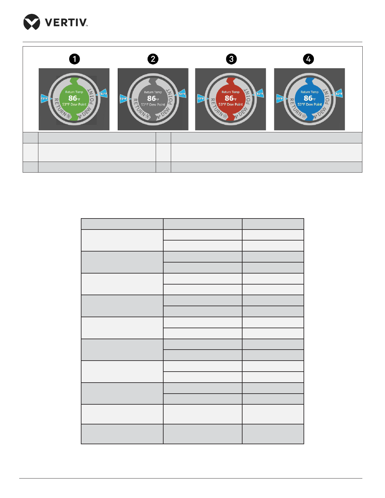
Vertiv | Liebert® PEX3™ Series Precision Air Conditioner | User Manual 62
Touchscreen Operation
No. Description No. Description
1 Sensor reading is within threshold limits 3 Sensor reading is above threshold limit or the unit is in an alarm
condition
2 Unit is powered-o 4 Sensor reading is below threshold limits
Figure 3-3 Dial Background Colors
Table 3-2 Background Color Displayed by Selected Value and Threshold Limit
Sensor/Value Selected Threshold Limit Background Color
Return Temp
None Blue
High return temperature Red
Return Humidity
Low return humidity Blue
High return humidity Red
Dew Point
Low dew point Blue
High dew point Red
Supply Temp
Low supply temperature Blue
High supply temperature Red
Average Rack Temp
Low remote temperature Blue
High remote temperature Red
Max Rack Temp
Low remote temperature Blue
High remote temperature Red
Min Rack Temp
Low remote temperature Blue
High remote temperature Red
Static Pressure
Low static pressure Blue
High static pressure Red
Outdoor Temp None Green
Outdoor Humidity None Green
Page 74
Vertiv | Liebert® PEX3™ Series Precision Air Conditioner | User Manual 63
Touchscreen Operation
3.3. Control Header
The control header contains the controls to access the user and service settings. The display is locked when
started initially and resumed after a period of inactivity.
3.3.1. Powering-On iCOM and Logging-in/ Unlocking Controls
iCOM is powered-ON when power is switched ON at the cooling unit’s disconnect switch and you activate
the display by touching it. iCOM is locked when started and also locks after a period of inactivity to prevent
unauthorized changes. A four digit password is required to access the user and service menus & options. The
advance menu is read-only at service level login.
• The factory-default inactivity period is a minute
• The factory-default password for user and service login are provided. We recommend changing the
passwords to prevent unauthorized changes.
• Default User Password = 1490
• Default Service Password = 5010
Steps to Unlock the Controls:
1. On the header, press . The keypad opens.
2. Press the numbers/ characters for your Password, then press .
Depending on the Password entered and your access level, the User and/ or Service options and view-only
access to the Advance menu are accessible. The details will be provided by accessing the User and Service
Menus.
3.3.2. Powering-on the Thermal Management Unit
Depending on the operating state, there are start/ stop priority switches that may prevent the cooling unit from
operating even though power to the unit is switched on and you have turned it on via iCOM. When all switches
are closed, then only the cooling unit operates. For example, even though you have turned-on the unit through
iCOM, if the BMS remote-monitoring system is sending a command to turn-o the unit, the cooling unit remains
O.
You must be logged-in to access the menu options See “Powering-On iCOM and Logging-in/ Unlocking
Controls”.
Page 75
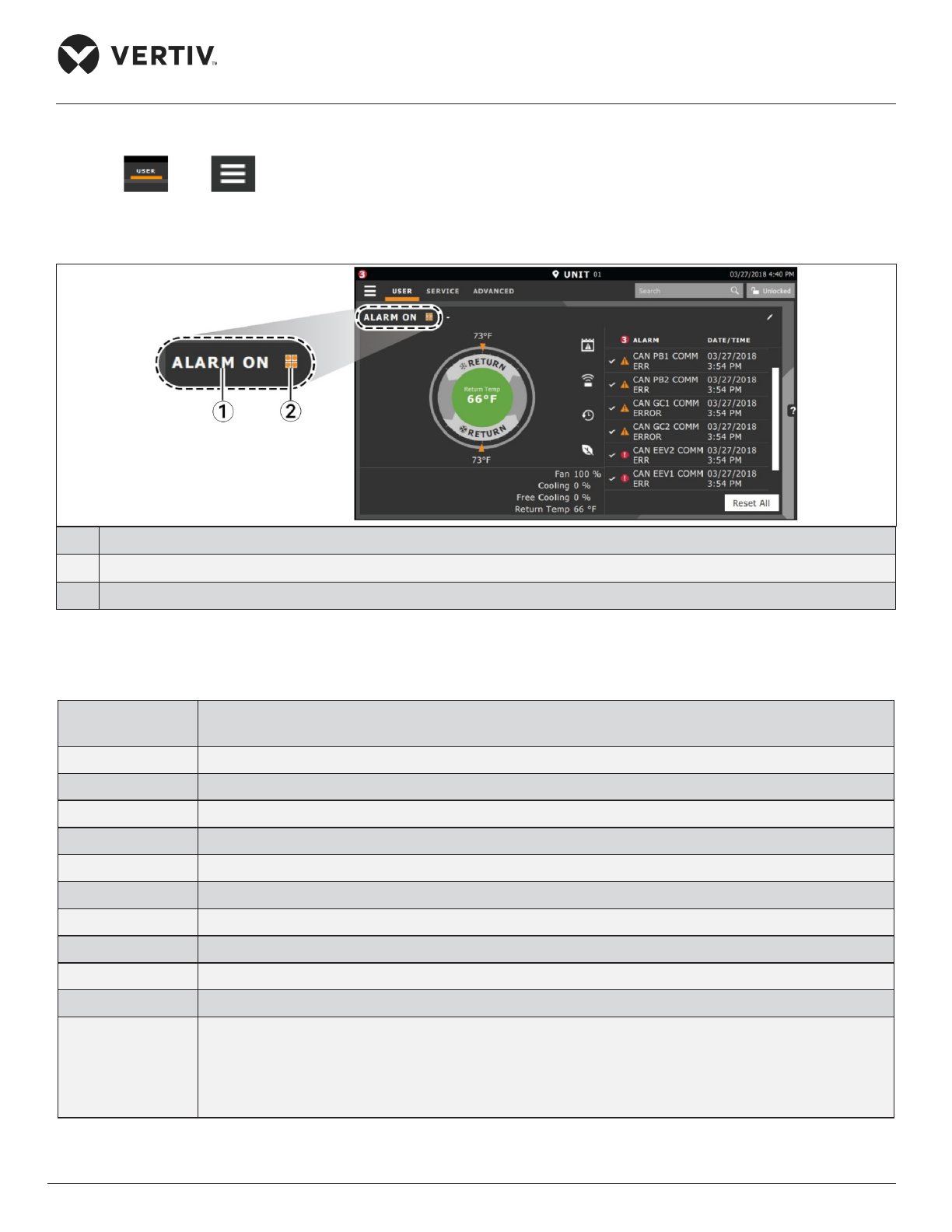
Vertiv | Liebert® PEX3™ Series Precision Air Conditioner | User Manual 64
Touchscreen Operation
To Power-On the Unit:
1. Press then > Turn Unit On, then Unit On dialog box opens.
2. Press Turn Unit On, then cooling unit starts, and the operating status is displayed as shown in Figure 3-4.
No. Description
1 Current status of the unit. See Cooling -unit status displayed as follow.
2 Teamwork icon. See Viewing Teamwork, Stand-by, Cascade Status.
Figure 3-4 Unit Status on iCOM Display
Table 3-3 Cooling Unit Status Displayed
Unit Status Text Description
ALARM OFF
An alarm forced the unit to turn o. See Viewing Unit Alarm.
MANUAL
Controlled by a service technician.
DISPLAY OFF
Unit is turned OFF at the iCOM display. See Powering-on the Thermal Management Unit.
ALARM STANDBY
In stand-by because of an active alarm on the unit see Viewing Unit Alarm.
STANDBY
In stand-by, because of service menu setting.
TIMER OFF
Scheduled on a timer and is in “sleep” mode waiting for the next start interval.
UNIT ON
Operating normally without alarm or warning.
WARNING ON
Active warning but still operating.
ALARM ON
Active alarm but still operating.
TIMER
Scheduled on a timer to operate and is in operating mode.
REMOTE OFF
• Turned-o by remote shutdown terminal.
• Occurs when a normally-closed set of 24 V contacts open.
• The remote On/ O and Display On/ O switches are in series, and the cooling unit will only turn-
on if both switches are “On/ Closed” or if one is “O/ Open”, the unit turns o.
Page 76
Vertiv | Liebert® PEX3™ Series Precision Air Conditioner | User Manual 65
Touchscreen Operation
Unit Status Text Description
MONITORING OFF
• Turned-o by remote monitoring system.
• Check the remote monitoring device or call Vertiv technician support for assistance.
BACK-DRAFT
Unit is non-operational, but EC fan is operating as a back-draft damper.
RESTART DELAY
Not yet operational after a power cycle because the restart- delay time is active.
3.3.3. Powering-O the Thermal Management Unit
1. Press then > Turn Unit O, then Turn Unit O panel opens.
2. Press ‘Turn Unit O’, the unit begins a power-O countdown then powers-O.
You must be logged-in to access the menu options. See Powering-on iCOM and Logging-in/ Unlocking
Controls.
3.3.4. Logging Out
Log-out occurs automatically when the display back light turns-O for inactivity.
1. To log-out manually, press the lock icon. The icon indicates “locked”.
The factory-default inactivity period is 1minute.
Page 77
Vertiv | Liebert® PEX3™ Series Precision Air Conditioner | User Manual 66
Touchscreen Operation
3.3.5. Setting the Date and Time
The correct date and time are critical for warnings, alarms, and scheduling.
1. Press then > Display Options >Display Properties > Date & Time.
2. Press the date eld, use the arrow to select the date and press Ok or press the time eld, use the arrow to
set the time, and press OK.
3. Select the date and time format if necessary.
4. Press Save.
The date selector has a preference switch in the upper-right corner. It helps in selecting between a
graphical or list view.
3.3.6. Searching
When logged-in, you can use the display search to nd the location of settings options based on a term, service
codes or parameter. You can also search by the line ID used in the iCOM before the touchscreen model.
1. In the control header, press the search eld. The keyboard opens.
2. Type the term and press . A list of locations that contain the searched term opens.
3. To go to a listed location, press an item, then press Go. The panel for the selected location opens.
4. Or to view the service codes and parameter entries related to the searched term, press View Parameter
Directory Entries (the number of related entries is included in the option). The Parameter Directory opens.
You may further rene the search in the directory.
You must be logged-in to access the display search. See Powering-on iCOM and Logging-in/ Unlocking
Controls.
Page 78
Vertiv | Liebert® PEX3™ Series Precision Air Conditioner | User Manual 67
Touchscreen Operation
3.3.7. Using Context-Sensitive Help
Pressing the Help icon on the right-hand side of the display opens the Help drawer with information
about the panel or dialog currently on the display.
1. You can use search and the topic index to nd further information.
2. To close the Help drawer, press the close arrow .
3.3.8. About iCOM Version
The version, build, and other rmware information for the iCOM display board may be helpful while servicing or
troubleshooting.
1. Press then >About. The ABOUT panel opens.
3.3.9. Accessing the User and Service Functions
iCOM operating functions that monitor and control a cooling unit are accessed via the User and Service menus.
1. To access a menu, press the icon for the menu you want, , or . In the control header, see
Control Header: The orange bar appears below the menu name when selected indicating the menu content
that will be displayed.
2. Press the menu icon . The menu opens.
You must be logged-in to access the menu options. See Powering-on iCOM and Logging-in/ Unlocking
Controls.
3.3.10. User Menu
The user menu lets you view system and unit status and edit some setpoints.
User menu options
1. Setpoints: Opens the SETPOINTS panel. See Viewing and Editing setpoints for the cooling unit.
2. Active Alarms: Opens the ALARMS panel. See Viewing Unit Alarms.
3. Event Log: Opens the EVENT LOG panel. See Viewing the Event Log.
Page 79

Vertiv | Liebert® PEX3™ Series Precision Air Conditioner | User Manual 68
Touchscreen Operation
4. Sensor Data: Opens the SENSOR DATA panel. See Viewing Sensor Data.
5. Display Options: Opens the Display Options menu:
• Customize Labels
• Display Properties
• Date & Time
6. Total Run Hours: Opens the RUN HOURS panel. See Managing Run Hours for a Component.
7. About: Opens the ABOUT panel. See About iCOM Version details
8. Turn Unit On/O: Depending on unit’s status, open the TURN UNIT ON or TURN UNIT OFF dialog. See
Powering-on the Thermal Management Unit or Powering-o the Thermal Management Unit
3.3.11. Service Menu
The service menu lets you view and edit setpoints and perform many other functions.
Service Menu Options
1. Setpoints: Opens the SETPOINTS panel.
2. Diagnostic/Service: Opens the Diagnostic/Service menu:
• Diagnostics
• Technical Support-contact information for the cooling unit and iCOM display
3. Alarm/Event Setup: Opens the ALARMS & EVENTS panel.
4. Economizer: Opens the panel for the economizer installed on the cooling unit.
5. BMS & Teamwork Setup: Opens the BMS & Teamwork Setup menu:
• U2U Setup
• Teamwork/Standby
• BMS Setup
6. Scheduler: Opens the SCHEDULER panel.
7. Options Setup: Opens the OPTIONS SETUP panel.
Page 80

Vertiv | Liebert® PEX3™ Series Precision Air Conditioner | User Manual 69
Touchscreen Operation
8. Auxiliary Device Setup: Opens the Auxiliary Device Setup menu:
• Sensors
• Analog Input
• Modbus Devices
• iCOM-DO
• CapCom
9. Backup & Security: Opens the Backup & Security menu:
• Control Upgrade
• Control Backup/ Replicate
• Control Files
• Display Upgrade
• Display Backup/ Replicate
10. Turn Unit On/ O: Depending on unit’s status, open the TURN UNIT ON or TURN UNIT OFF dialog. See
Powering-on the Thermal Management Unit or Powering-o the Thermal Management Unit.
3.3.12. Advanced Menu
The advanced menu provides a read-only view of the advanced set-up and factory-level settings.
1. Advanced Menu Options:
2. Factory Settings: Unit-code and conguration settings.
3. Diagnostic: Details about control and cooling operation.
4. Expert Settings: Parameters and settings for use by trained professionals only.
5. Compressor Info: Details about compressor state and operating mode.
6. Tandem Info: Details about compressor state and operating mode.
7. MBV Settings: Motorized ball valve settings (water-cooled heat rejection).
8. Running Monitoring: Details about component run times.
Page 81
Vertiv | Liebert® PEX3™ Series Precision Air Conditioner | User Manual 70
Touchscreen Operation
9. Modbus Devices: Information about connected Modbus devices such as power and ow meters.
10. Control Override: Allows simulating events and override of analog outputs beyond normal limits.
11. EEV Settings: Electronic Expansion Valve settings.
12. MC Condenser: Details about MC condenser (air-cooled heat rejection).
13. Parameter Directory: A searchable list of all parameters in the user interface.
3.4. User Operation
Viewing and Editing setpoints for the cooling unit.
• User-level access allows viewing and editing of only a limited number of setpoints. To view or adjust all
setpoints, you must have service-level access.
• Depending on the type of thermal management unit, included components and control settings of your
system, the options on your iCOM display may dier.
3.4.1. Editing Humidity Setpoints
1. Press then > Setpoints > Humidity Control. The Humidity Control secondary panel opens.
2. Adjust the setpoint options, then press Save. The setpoint will be updated.
3. Press Cancel to discard the changes.
3.4.2. Editing Temperature Setpoints
1. Press then > Setpoints > Temperature Control. The Temperature Control secondary panel
opens.
2. Adjust the setpoint options, then press Save. The setpoint will be updated.
3. Press Cancel to discard the changes.
Page 82
Vertiv | Liebert® PEX3™ Series Precision Air Conditioner | User Manual 71
Touchscreen Operation
3.4.3. Viewing Unit Alarms
The ALARMS panel lists active alarm and warning events. Table 3-4 below describes the type and state of the
alarm shown by indicator dots.
Table 3-4 Alarm Status/ Indicator
Indicator Description
Yellow dot Warning event
Red dot Alarm event
Circle
Event condition has cleared, but still must be
acknowledge. See the Acknowledge Alarm
To view alarms
1. Press then >Alarms. The ALARMS panel opens.
2. Press an alarm to display the ALARM DETAILS panel.
3.4.4. Silencing an Audible Alarm
Touch the screen to silence an audible alarm. If the alarm is non-latching, the alarm silences when the condition
clears.
The audible alarm must be enabled in display options to make sound.
3.4.5. Acknowledging Alarms
Depending on the notication settings, alarms and warnings must be acknowledged or reset. An event is active
as long as it is unacknowledged, with the exception of the network-failure events described in Table 3-5. Once
acknowledged, an event remains active until the situation that triggered the event is resolved, see Table 3-4 for
event-status indicators. When the event is acknowledged and cleared, it is removed from the Alarms panel and
the LED stops ashing red.
Acknowledging alarm events does not clear them, to clear an issue, it must be corrected, reset automatically
by the controller or reset manually.
Page 83
Vertiv | Liebert® PEX3™ Series Precision Air Conditioner | User Manual 72
Touchscreen Operation
To acknowledge alarms
1. On the ALARMS panel, press Acknowledge All: A check mark overlays the status indicator of the active
alarms and warnings, and these automatically clears when the condition is no longer present.
2. If a critical event must be reset manually, then the acknowledged items are listed with a Reset All button on
the ALARMS panel.
3. Touch Reset All to manually reset the condition.
Table 3-5 Events that Clear without Acknowledgment
Network Failure Description
Unit xx
disconnected
• The iCOM I/O board assigned as U2U address number XX (two up to thirty- two) has lost
communication with the group
• Make sure all units are powered-on at the disconnect
• Check cable connections and network setting wherever applicable
No connection
W/unit 1
• The iCOM I/O board assigned as U2U address number 1 has lost communication with the
group
• Make sure all units are powered-on at the disconnect
• Check cable connections and network setting wherever applicable
BMS disconnect
• The BMS/ BAS has not completed a handshake within the time dened by the BMS/ BAS
• Verify monitoring connection and communication to the BMS/ BAS panel
Unit code missing The Factory unit code must be conrmed, saved and executed
Unit code mismatch The Factory unit code must be conrmed, saved and executed
Ambient sensor
failure
The outdoor temperature/ humidity sensor used on the air economizer unit has become
disconnected or is no longer working properly
3.4.6. Viewing the Event Log
The event log is a list by date/ time of the last 400 events generated by iCOM for the thermal-management
unit. On the User menu, press Event Log. The EVENT LOG for the cooling unit opens. Table 3-6 describes the
color-coded status for each event.
Depending on the type of thermal management unit, included components and control settings of your
system, the options on your iCOM display may dier.
Page 84
Vertiv | Liebert® PEX3™ Series Precision Air Conditioner | User Manual 73
Touchscreen Operation
Table 3-6 Events that Clear without Acknowledgment
Indicator Description
Green Dot Message
Yellow Dot Unacknowledged warning event. See acknowledge alarm on the previous page
Red Dot Unacknowledged alarm event. See acknowledge alarm on the previous page
White Dot with check-mark overlay Acknowledged event, the cause still exists
White circle Acknowledged event, the cause is cleared
3.4.7. Viewing Sensor Data
The Sensor Data panel lists the standard and optional sensors monitored by iCOM and the current readings of
each sensor.
1. Press then > Sensor Data. The Sensor Data panel opens.
2. A secondary panel displays the DAILY SENSOR READING SUMMARY, which shows temperature, humidity
and dew-point readings for the cooling unit.
3.4.8. Managing Run Hours for a Component
You can view the run hours for components on a cooling unit, set the total-run-time limit, and reset total run
hours to zero.
1. Press then > Total Run Hours. The RUN HOURS panel opens and the current hours for each
component are listed in the Total Run Hours column (to reset the total run hours to zero, refer Section 3.4.9
Setting run hours to zero).
2. Use the slider to set the total-run-time limit for each component, then press Save to set the limits.
3.4.9. Setting Run Hours to Zero
1. On the RUN HOURS panel, press to check each box in the Total Run Hours column next to the component
(s) to reset. The Set to Zero button is enabled.
2. Press Set to Zero, the total run hours for selected component (s) will set to zero.
Page 85
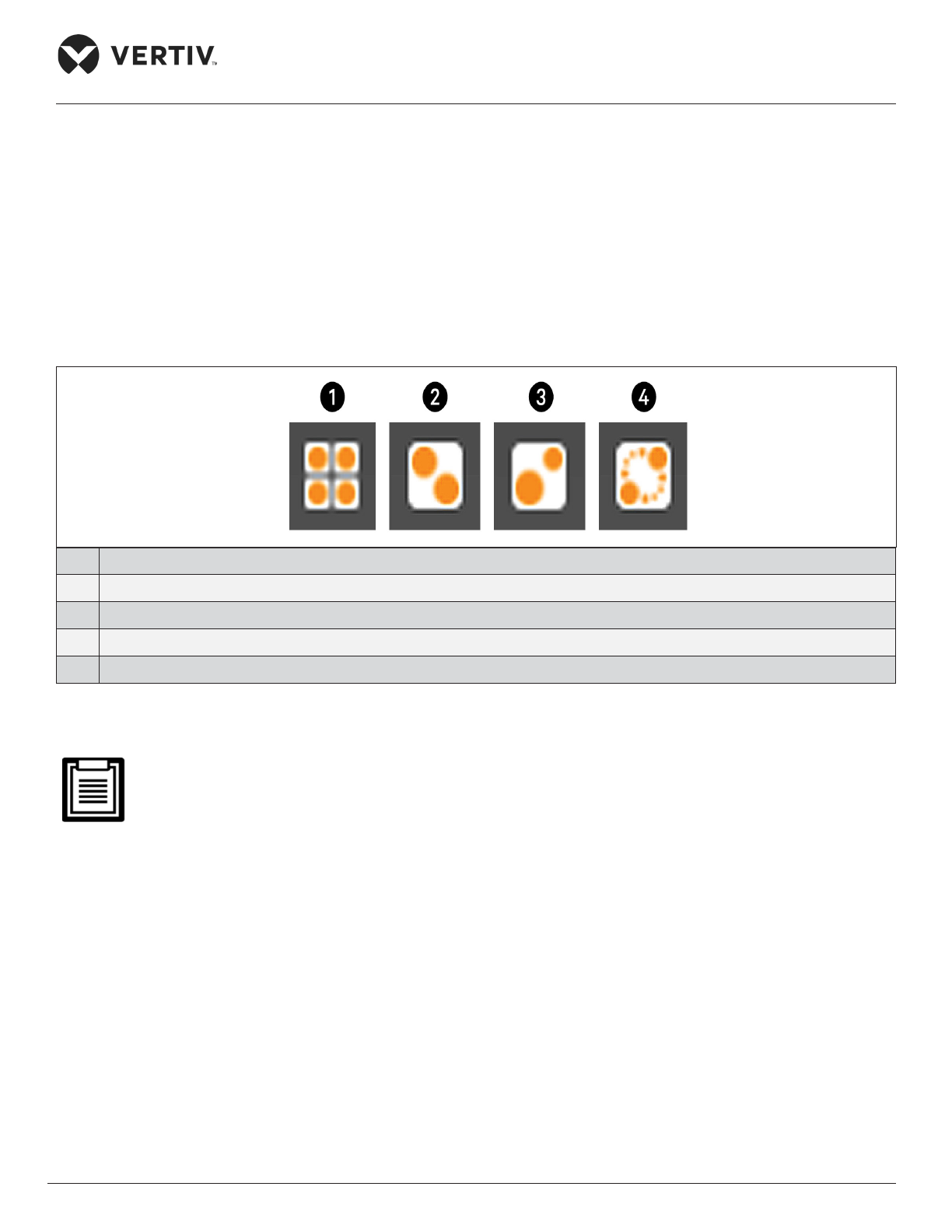
Vertiv | Liebert® PEX3™ Series Precision Air Conditioner | User Manual 74
Touchscreen Operation
3.4.10. Viewing Teamwork, Stand-by, Cascade and Operating Status
In the main User panel, the Teamwork Mode icon indicates the mode selected, see Figure 3-5.
To view the teamwork details
1. Press the Teamwork-mode icon.
2. The teamwork dialog opens display the teamwork mode, number of units in stand-by, and number of
operating units.
No. Description
1 No teamwork
2 Mode 1- Parallel Teamwork
3 Mode 2- Independent Teamwork
4 Mode 3- Optimized Aisle Teamwork
Figure 3-5 Teamwork icons
You must be logged-in with the Service Password to edit teamwork mode. Refer Powering-on iCOM and
Logging-in/ Unlocking Controls.
Page 86
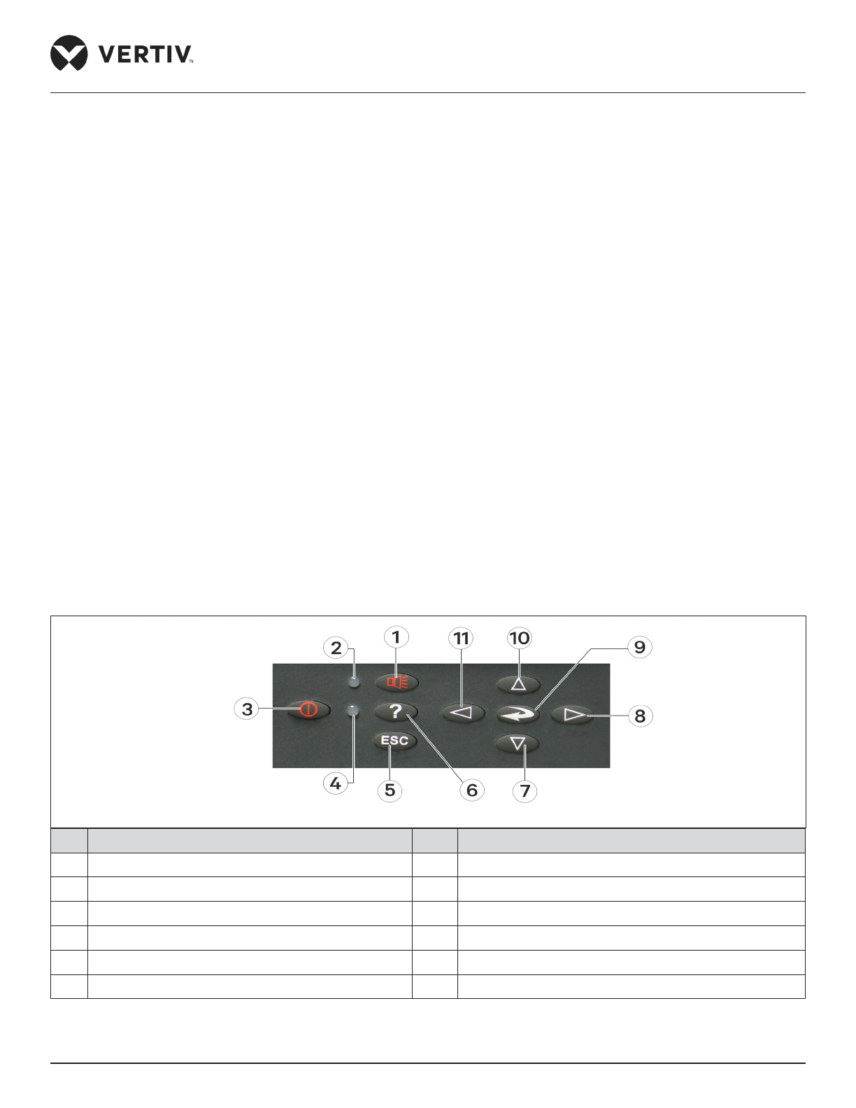
Vertiv | Liebert® PEX3™ Series Precision Air Conditioner | User Manual 75
iCOM Controller Operation
Chapter 4: iCOM Controller Operation
This chapter explains the LCD, Button, Indicator Panel, Structure Chart of Control Menu, Start-Up Interface,
Main Interface, User Menus, Service Menus, Advanced Menus and Event Name and Denition of the iCOM
Controller. The iCOM controller adopts menu operation. The display board monitors, displays, and the user may
operate the parameters on the display board to control the environment within a set range.
4.1. LCD Screen
LCD Screen is located on the front panel of the Liebert PEX3 series. The LCD displays the current state of
the equipment room such as temperature, humidity and so on. You can also read and modify the equipment
conguration through the LCD. The LCD uses white back-light, if no button is pressed within a certain period of
time (settable; default: 5min), the back-light turns o until any one button of the panel is pressed.
4.2. Button and Indicator Panel
Nine buttons and two indicators are located on the button & indicator panel as shown in Figure 4-1, Including:
• Indicators: alarm indicator and operation indicator
Buttons: ON/ OFF button, Enter button, ESC button, Up button, Down button, Left button, Right button, Alarm
silence button, and Help button.
No. Description No. Description
1 Alarm silence button 7 Down button
2 Alarm indicator 8 Right button
3 ON/OFF button 9 Enter button
4 Operation indicator 10 Up button
5 ESC button 11 Left button
6 Help button
Figure 4-1 Button and Indicator Panel
Page 87
Vertiv | Liebert® PEX3™ Series Precision Air Conditioner | User Manual 76
iCOM Controller Operation
The indicators are described in Figure 4-2. The functions of the buttons are described in Table 4-2.
Table 4-1 Indicator Description
Indicator Description
Alarm indicator The alarm indicator turns on red upon alarms triggered. It is o after the alarm has been cleared
Operation indicator
The operation indicator turns on green when the unit is operating. When the unit is shut down,
the indicator is yellow
• After the system is powered on, the system will resume the operation state before power-o. For example,
if the system is in the work state when its powered o, it goes to the work state automatically after
power-on. You do not need to start it manually.
• When the system is in the test state, the setpoints will not be written into the iCOM controller.
Table 4-2 Button Description
Button Function Description
ON/OFF
button
• Switch on/ o the system. Press the ON/ OFF button to shut down the unit, or to start an idle system.
• Test the display state of the back-light of the LCD and the operation indicator.
• After powering-on, when the system is stand-by (dened as test state in this manual), press the ON/
OFF button to turn on the unit, the indicator turns to green, and the LCD
back-light turns on. This is for testing whether the LCD back-light and the operation indicator are
normal.
Enter
button
• Enter the selected menu or save the setting after parameters are changed. Select the menu or
parameter by pressing the direction button, the menu and the parameter is high-lighted.
• Test the display of characters.
• When the system is in the test state, press the Enter button that will display the ASCII code. This
function is used to test whether the characters are displayed normally on the LCD.
ESC
button
• Quit the current menu.
• Abolish the current change of parameters.
• Test the LCD high light.
• Press the ESC button to switch the LCD between light and high light when the system is in the test
state. This function can test whether the LCD high light is normal.
Up button
• Increase the value of the displayed parameters during parameter setting.
• Scroll a row or a screen up in the query state.
• Test the buzzer.
• Press the Up button when the system is in the test state to increase the buzzing frequency (initial
value: 0%). Meanwhile the buzzer will sound at the set frequency This function is used to test whether
the buzzer is normal.
Page 88

Vertiv | Liebert® PEX3™ Series Precision Air Conditioner | User Manual 77
iCOM Controller Operation
Button Function Description
Down
button
• Decrease the value of the displayed parameters during parameter setting.
• Scroll a row or a screen down in the query state.
• Test the buzzer.
• If the buzzer frequency is not 0%, press the down button to decrease the buzzing frequency when the
system is in the test state. Meanwhile the buzzer will sound at the set frequency. This function is used
to test whether the buzzer is normal.
Left
button
• Select the left bit during the parameter setting operation.
• Test the LCD contrast.
• Press the Left button when the system is in the test state to decrease the LCD contrast (by default:
100%) This function is used to test whether the LCD contrast is normal.
Right
button
• Select the right bit during the parameter setting operation.
• Test the LCD contrast.
• If the LCD contrast is not 100%, press the right button when the system is in the test state to increase
the LCD contrast. This function is used to test whether the LCD contrast is normal.
Alarm
silence
button
• The system will issue an alarm sound upon alarms. If you press the Alarm Silence button, the alarm
sound will be eliminated.
• Clear the current alarm after the alarm sound is silenced.
• Test the alarm indicator and rest the LCD contrast and buzzer frequency.
• Press the alarm silence button when the system is in the test state to switch the alarm indicator
between on and o. It can test whether the alarm indicator is normal. Meanwhile, reset the LCD
contrast to 100% and buzzer frequency to 0%.
Help
button
• Display the online help.
• Test the yellow display of the LCD operation indicator.
• When the system is in the test state, press the Help button to switch on and o the LCD operation
indicator. This function is used to test whether the yellow display of the LCD operation indicator is
normal.
4.3. Structure Chart of Control Menu
Please refer to Appendix-III Menu Structure of iCOM Controller.
Page 89
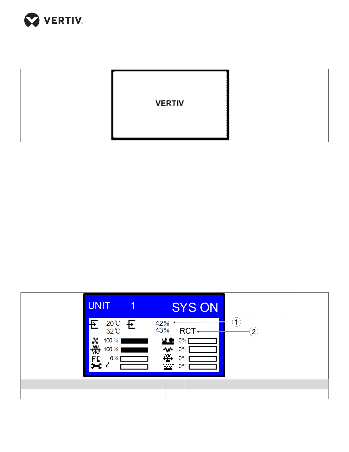
Vertiv | Liebert® PEX3™ Series Precision Air Conditioner | User Manual 78
iCOM Controller Operation
4.4. Start-Up Interface
After the system is powered on, it is in the waiting state. The LCD will display the interface shown in Figure 4-2.
Figure 4-2 Startup Interface
4.5. Main Interface
After power-on, the LCD will enter the main interface after about 60s. The main interface provides the general
information about relative equipment status, including current temperature and humidity; temperature and
humidity setpoints; equipment output status (fan, compressor, cooling, heating, dehumidifying, humidifying);
alarm and maintenance status.
The main interface has two display modes: Graphical and Simple. The dierence between these two display
modes is that the graphical interface (see Figure 4-3) displays the percentage output chart of the function
components, while the simple interface (see Figure 4-4) displays only the icons of current operation mode only.
The switching of two modes can be realized by operating the menu. For details, refer to DISPLAY SETUP.
The upper left corner of the main interface displays the current unit number; the upper right corner displays
the current system status If there is no button operation for 255s on other menu display screen, the LCD screen
returns to the main interface.
No. Description No. Description
1 Setpoint 2 Present value
Figure 4-3 Graphical Mode of Main Interface
Page 90
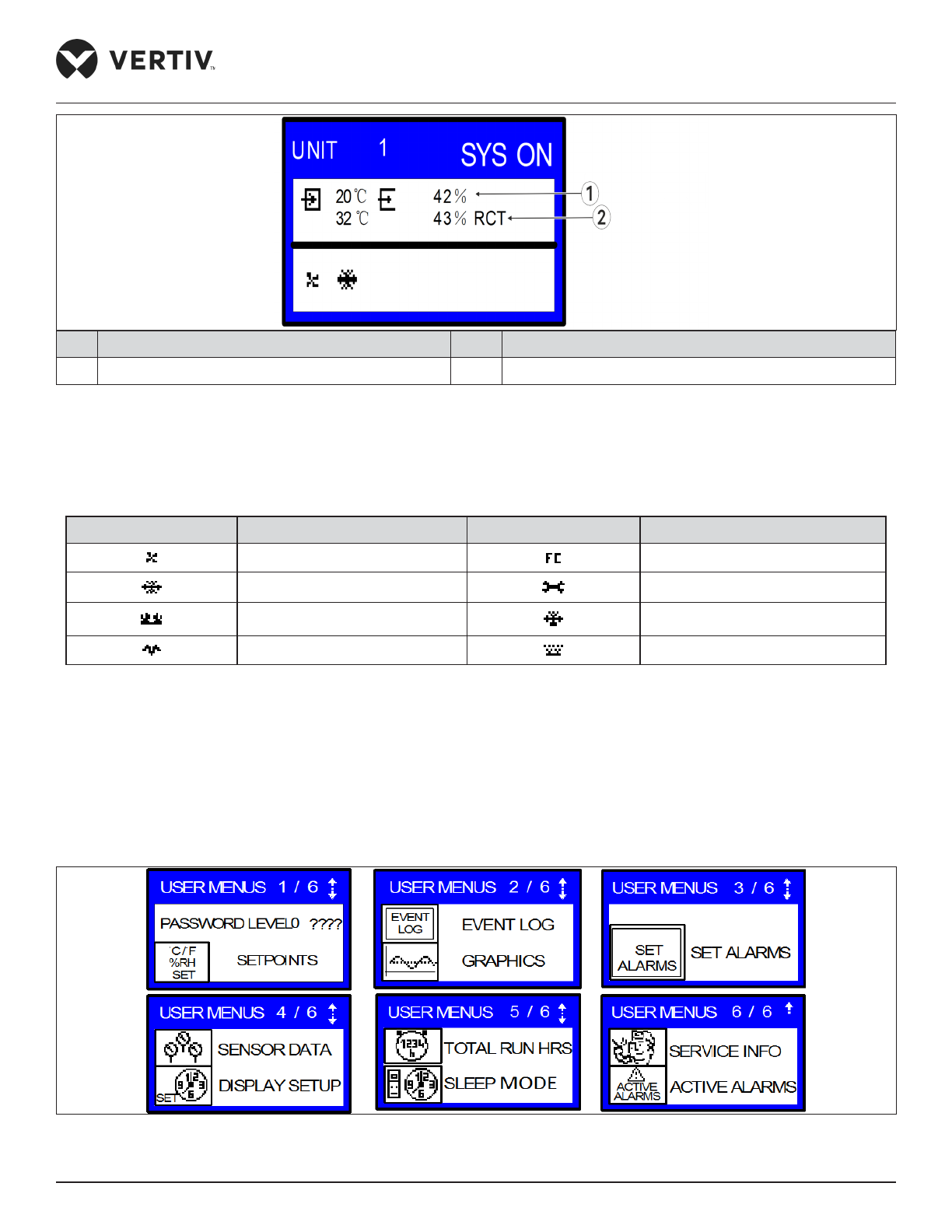
Vertiv | Liebert® PEX3™ Series Precision Air Conditioner | User Manual 79
iCOM Controller Operation
No. Description No. Description
1 Setpoint 2 Present value
Figure 4-4 Simple Mode of Main Interface
The icons of the graphical and simple modes on the main interface are dened in Table 4-3.
Table 4-3 Denition of Icons
Icon Denition Icon Denition
Fan running Free cooling
Cooling Maintenance
Hot water heating Dehumidifying
Electrical heating Humidifying
4.6. User Menus
Press the enter or down button on the main interface to enter the User Menus, as shown in Figure 4-5. The
User Menus are displayed in six pages, each displaying one or two submenus. Press the Enter button to
highlight the submenu, the Up or Down button to browse the submenus, and the Enter button to enter the
selected one.
Figure 4-5 User Menus
Page 91

Vertiv | Liebert® PEX3™ Series Precision Air Conditioner | User Manual 80
iCOM Controller Operation
4.7. Password
The password is necessary for dierent level menus. After entering the password (user password: 149), use the
up and down navigation buttons to browse/ change all the options/parameters in User Menu, and then press
the enter button to enter the selected option.
4.8. Setpoints
The setpoints disappear when the power is lost. Use the User Menus to browse and set parameters in the
SETPOINTS submenu. The left row displays the parameter codes; the middle row; the parameter name; the
right row and the setpoints, as shown in Table 4-4.
Table 4-4 Descriptions of Setpoint Parameters
Parameters Default Setting range Description
U102 TEMP SET 23.0 °C 5.0 °C to 40.0 °C Air Temperature Setpoint
U102 TEMP ACT -
5.0 °C to 40.0 °C
Actual Air Temperature Setpoint
U103 TEMPSENS Return Sensor
0 = SUP
1 = REM
2 = RET
Temperature Control Sensor
U104 HUM SET
50% 20% to 80% Humidity Setpoint
12.0 °C 5.0 °C to 30.0 °C Dew Point Setpoint
U105 SUP SENS No No, Lim, Ctrl, Cool Supply Air Type
U106 HUM CTRL Predictive
0 = Rel
1 = Comp
2 = Pred
3 = DewP
Humidity Control Type
U107 FAN SET 23.0 °C
5.0 °C to 40.0 °C Fan Speed Temperature Setpoint
U108 FAN SENS Return Sensor
0 = SUP
1 = REM
2 = RET
3 = MAN
Fan Control Sensor
U110 SMART AI -
0 = No
1 = Yes
Smart Aisle Enabled
U113 2ND SETP 23.0 °C 5.0 °C to 40.0 °C 2nd Temperature Setpoint
U114 SUP TEMP 5.0 °C
5.0 °C to 27.0 °C
Supply Temp Limit Setpoint
U116 BACK TSP 23.0 °C
5.0 °C to 40.0 °C
BMS Backup Temp Setpoint
U117 BACK FAN 23.0 °C
5.0 °C to 40.0 °C
BMS Backup Fan Setpoint
U119 RCOMP SP
23.0 °C
5.0 °C to 40.0 °C
Return Compensation Setpoint
If you want to modify the preceding setpoints, enter the password before entering the SETPOINTS menu. Then
press the Enter button to enter the submenu and use the Up and Down button to scroll the options. Press the
Enter button to select one parameter, use the Up or Down button to set the value, and press the Enter button
to save the change.
Page 92
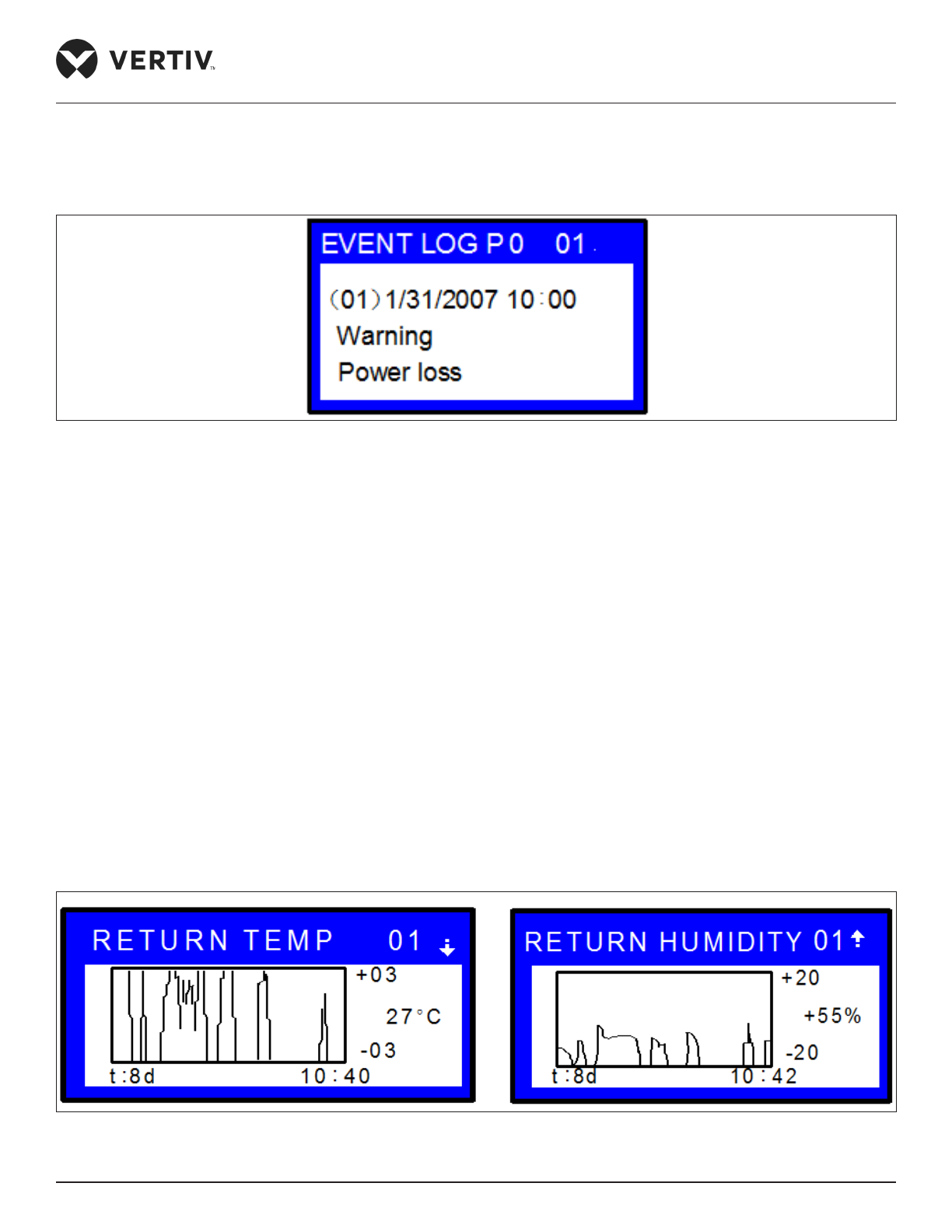
Vertiv | Liebert® PEX3™ Series Precision Air Conditioner | User Manual 81
iCOM Controller Operation
4.9. Event Log
You can enter the EVENT LOG menu without a password, as shown in the Figure 4-6.
Figure 4-6 Event Log Menu
The EVENT LOG menu saves the last 400 system records. The event types include message, warning and
alarm
• When the event type shows ‘Message’, the LCD will display the event name only.
• When the event type shows ‘Warning’, the LCD will display the event name and the alarm indicator turns red.
• When the event type shows ‘Alarm’, the LCD will display the event name, the alarm indicator will turn red, and
an audible alarm will be raised.
4.10. Graphics
The GRAPHICS menu provides two types of graphs: RETURN TEMP and RETURN HUMIDITY. These graphs
reect the temperature and humidity changes over a period of time in the past.
In the graphs, the current temperature or humidity is the origin, the time is the horizontal axis, and the
temperature or humidity is the vertical axis, as shown in the Figure 4-7.
Figure 4-7 The Graph of Return Temperature and Return Humidity
Page 93
Vertiv | Liebert® PEX3™ Series Precision Air Conditioner | User Manual 82
iCOM Controller Operation
As the horizontal axis, the time range can be set into eight types. Each pixel indicates dierent time in dierent
time ranges. See Table 4-5 for the detailed time range. The scaling of the vertical axis can also be set for the
RETURN TEMP, the scaling range is ± 3 to ± 20: For the RETURN HUMIDITY, the scaling range is
± 10 to ± 30. The greater the scaling range, the greater the value each pixel and the more centered the curves.
Parameters can be set without entering the password. Press the enter button to highlight the parameters, use
the up or down button to select a parameter. Then press the enter button again to enter the parameter and use
the up or down button to set the value. Press the enter button to nally save the change.
Table 4-5 Time Range
Time Range Time Indicated by each Pixel Time Range Time Indicated by each Pixel
8min 6s 2d 36min
32min 24s 4d 72min
1hr 45s 8d 144min
12hr 9min 16d 288min
24hr 18min
4.11. Set Alarms
The SET ALARMS menu is used to set the upper and lower limits of temperature and humidity alarms. The
settings will not be lost when the power fails. You can select the ‘SET ALARMS’ submenu to browse and set the
parameters through the USER MENUS. The parameters are described in Table 4-6.
It is recommended not to change the system defaults. If you consider it necessary to change the defaults,
consult Vertiv personnel.
Table 4-6 Descriptions of SET ALARMS Parameters
Parameters Default Setting Range Description
U202 RTN SNSR Yes Yes, No Return air sensor alarm enable
U203 HI TEMP 37.8 °C 1.0 °C to 99.0 °C High return air temperature threshold
U204 LO TEMP 18.3 °C 1.0 °C to 99.0 °C Low return air temperature threshold
U205 HI HUM 65% 1% to 99% High return air humidity threshold
U206 LO HUM 35% 1% to 99% Low return air humidity threshold
U207 SENSOR A No Yes, No Sensor alarm enable
U208 HI TEMPA 32.3 °C 1.0 °C to 99.0 °C High temperature threshold of sensor A
U209 LO TEMPA 12.8 °C 1.0 °C to 99.0 °C Low temperature threshold of sensor A
U210 HI HUM A 70% 1% to 99% High humidity threshold of sensor A
U211 LO HUM A 30% 1% to 99% Low humidity threshold of sensor A
U213 SUP SNSR Yes Yes, No Supply air alarm enable
Page 94

Vertiv | Liebert® PEX3™ Series Precision Air Conditioner | User Manual 83
iCOM Controller Operation
Parameters Default Setting Range Description
U214 HI SUP T 23.9 °C 1.0 °C to 99.0 °C High supply air temperature threshold
U215 LO SUP T 10.0 °C 1.0 °C to 99.0 °C Low supply air temperature threshold
U219 REM SNSR Disabled
0 = No
1 = Com
2 = Sep
Remote Sensor Alarms
U220 HI REM 32.3 °C 1.0 °C to 99.0 °C High Remote Temperature
U220 LO REM 12.8 °C 1.0 °C to 99.0 °C Low Remote Temperature
U224 HIREM 01 32.3 °C 1.0 °C to 99.0 °C High Remote Temperature 01
U224 LOREM 01 12.8 °C 1.0 °C to 99.0 °C Low Remote Temperature 01
U225 HIREM 02 32.3 °C 1.0 °C to 99.0 °C High Remote Temperature 02
U225 LOREM 02 12.8 °C 1.0 °C to 99.0 °C Low Remote Temperature 02
U226 HIREM 03 32.3 °C 1.0 °C to 99.0 °C High Remote Temperature 03
U226 LOREM 03 12.8 °C 1.0 °C to 99.0 °C Low Remote Temperature 03
U227 HIREM 04 32.3 °C 1.0 °C to 99.0 °C High Remote Temperature 04
U227 LOREM 04 12.8 °C 1.0 °C to 99.0 °C Low Remote Temperature 04
U228 HIREM 05 32.3 °C 1.0 °C to 99.0 °C High Remote Temperature 05
U228 LOREM 05 12.8 °C 1.0 °C to 99.0 °C Low Remote Temperature 05
U229 HIREM 06 32.3 °C 1.0 °C to 99.0 °C High Remote Temperature 06
U229 LOREM 06 12.8 °C 1.0 °C to 99.0 °C Low Remote Temperature 06
U230 HIREM 07 32.3 °C 1.0 °C to 99.0 °C High Remote Temperature 07
U230 LOREM 07 12.8 °C 1.0 °C to 99.0 °C Low Remote Temperature 07
U231 HIREM 08 32.3 °C 1.0 °C to 99.0 °C High Remote Temperature 08
U231 LOREM 08 12.8 °C 1.0 °C to 99.0 °C Low Remote Temperature 08
U232 HIREM 09 32.3 °C 1.0 °C to 99.0 °C High Remote Temperature 09
U232 LOREM 09 12.8 °C 1.0 °C to 99.0 °C Low Remote Temperature 09
U233 HIREM 10 32.3 °C 1.0 °C to 99.0 °C High Remote Temperature 10
U233 LOREM 10 12.8 °C 1.0 °C to 99.0 °C Low Remote Temperature 10
To browse through the menu, press the enter button to highlight the option, and use the up or down button
to scroll. Password is required for changing the setpoints. Then, enter the SET ALARMS menu, press the enter
button to highlight the option, use the up or down button to browse the submenu. Press the enter button to
enter the selected parameter. Use the up or down button to change the setpoints, and press the enter button
to save the change, or press the ESC button to quit the change.
4.12. Display Setup
The DISPLAY SETUP menu is used to set the LCD display attributes. Password is not required for changing the
setpoints. The parameters are described in the Table 4-7.
Page 95

Vertiv | Liebert® PEX3™ Series Precision Air Conditioner | User Manual 84
iCOM Controller Operation
Table 4-7 Descriptions of DISPLAY SETUP Parameters
Parameters Default Setting range Description
U401 LANGUAGE EN
RUS, CZE, CHI,
ESP, FRE, ITA,
DEU, EN, POR
Language options
U402 YEAR 2005 - Current year
U402 MONTH 04 01 to 12 Current month
U402 DAY 19 01 to 31 Current day
U403 HOUR 19h - Current hour
U403 MINUTE 8min - Current minute
U403 SECOND 17s - Current second
U404 TEMP F/C °C °F, °C Temperature indication
U405 CONTRAST 50% From 0% to 100% Display contract
U406 BUZ FREQ 50% From 0% to 100% Buzzer frequency. 0% means buzzer silenced
U406 BUZ TEST O On, O
Buzzer frequency test switch. It determines whether or not
there will be sound accompanying the adjustment of BUZ
FREQ through the setting
U407 BACKLITE 5min
5min, 10min,
30min, 1hr, 12hr
Backlight time, or the backlight time when there is no
button operation
U408 SCREEN Graph
Graph, Simple,
SimCo, GraCo
Main interface display mode
U409 SHOWS A + S SET, ACT, A + S
Main interface display mode of setpoints and actual values
Range:
SET: only setpoints of the temperature and humidity are
displayed.
ACT: only actual temperature and humidity are displayed.
A + S: both setpoints and actual values of the temperature
and humidity are displayed.
U410 DISPLAY Norm
Norm (normal),
Inv
Display color
U411 DATE m/d/y m/d/y, dmy, ymd Date display format
4.13. Total Run Hrs
The TOTAL RUN HRS menu records the total run time (unit: hr) of the system components. You can also set
the run time limits of the system components through this menu. If the actual component run time exceeds the
set limit, alarms is triggered.
This menu requires password. You can reset the total run time to zero to restart timing. The parameters on
this menu are described in the Table 4-8. Each component has a LIMIT option to set the run time limit of the
corresponding component.
Page 96
Vertiv | Liebert® PEX3™ Series Precision Air Conditioner | User Manual 85
iCOM Controller Operation
Table 4-8 Descriptions of TOTAL RUN HRS Parameters
Parameters Default Related component Parameters Default Related component
U502
MOTOR
(S)
1000hr
Fan motor
U507 HG/HW 23hr Hot gas/ Hot water
U502 LIMIT 32000hr U508 EL HEAT1 -
Electric reheat 1
U503 COMP1 500hr
Compressor 1
U508 LIMIT 0hr
U503 LIMIT 32000hr U509 EL HEAT2 -
Electric reheat 2
U504 COMP2 500hr
Compressor 2
U509 LIMIT 0hr
U504 LIMIT 32000hr U510 EL HEAT3 -
Electric reheat 3
U505 CW -
Chilled Water
U510 LIMIT 0hr
U505 - - U511 HUM -
Humidier
U506 LIMIT 3200hr
Free Cooling
U511 LIMIT 0hr
U506 FC 23hr U512 DEHUM -
Dehumidier
U507
LIMIT 3200hr
Hot gas/ Hot water U512
LIMIT 0hr
Timers resetting is not needed unless the components are replaced.
Page 97
Vertiv | Liebert® PEX3™ Series Precision Air Conditioner | User Manual 86
iCOM Controller Operation
4.14. Sleep Mode
In the sleep mode, the air conditioner unit can realize auto-On/ O. Through the SLEEP MODE menu, you can
set two-time zones of the sleep mode, and select the sleep timing mode. The parameters on this menu are
described in Table 4-9.
Table 4-9 Descriptions of SLEEP MODE Parameters
Parameters Default Setting Range Description
U602 SLEEP EN No
Yes, No
Sleep mode day, including Monday ~ Sunday. Set the value of any
day to ‘Yes’, and the system will enter sleep mode on that day every
week. This parameter works together with the following hour and
minute settings to designate an exact time
U604 MON No
U604 TUE No
U604 WED No
U604 THU No
U604 FRI No
U604 SAT No
U604 SUN No
U606 START 1 0hr
-
Sleep mode start time 1. The rst parameter is used to set the hour
of time, and the second one is used to set the minute of time
U606 START 1 0m
U606 STOP 1 0hr
Sleep mode end time 1. The rst parameter is used to set the hour of
time, and the second one is used to set the minute of time
U606 STOP 1 0min
U608 START 2 0hr
Sleep mode start time 2. The rst parameter is used to set the hour
of time, and the second one is used to set the minute of time
U608 START 2 0min
U608 STOP 2 0hr
Sleep mode end time 2. The rst parameter is used to set the hour of
time, and the second one is used to set the minute of time
U608 STOP 2 0min
U609 TIME MOD Yes Auto, Yes, No
Timing mode setting range. Auto: during the system sleep time, if
high/low temperature occurs, the system will resume operation and
mask the alarm for 15min The system will re-enter the sleep mode
after the alarm is cleared.
Yes: start sleep mode; No: no sleep mode
U610 TIME TYP S.OFF S.OFF, DEADB Timing mode selection
U611 DEADBAND 2.3 K 2 K to 15 K Used to set the deadband temperature setting range
4.15. Service Info
The SERVICE INFO menu provides the contact information of customer service personnel. This information is
read only.
4.16. Active Alarms
The ACTIVE ALARMS menu displays the active alarms of the system. No password is required to access this
menu.
Page 98
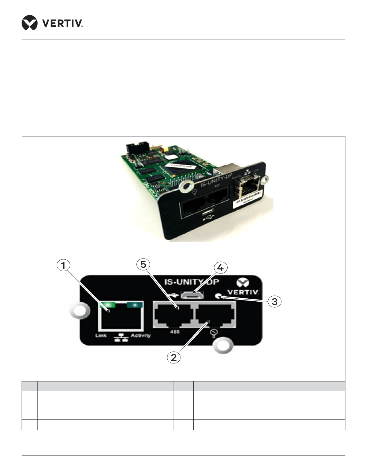
Vertiv | Liebert® PEX3™ Series Precision Air Conditioner | User Manual 87
Application of INTELLI SLOT
Chapter 5: Application of INTELLI SLOT
This chapter introduces the application of the host communication components INTELLI SLOT, including
installation and commissioning of the host communication card.
5.1. Introduction of Host Communication Card
Liebert PEX3 supports IS-UNITY-DP card, shown in the Figure 5-1.
No. Description No. Description
1 RJ-45-Ethernet:- HTTP; Modbus TCP; BACnet IP;
SNMPv1,v2e,v3; Vertiv protocol
4 Micro- USB AB (Future release)
2 Liebert sensor network (Future release) 5 BACnet; MSTP; Modbus RTU YDN23
3 Reset button (Reboot or reset to factory defaults)
Figure 5-1 IS-UNITY-DP Card
Page 99
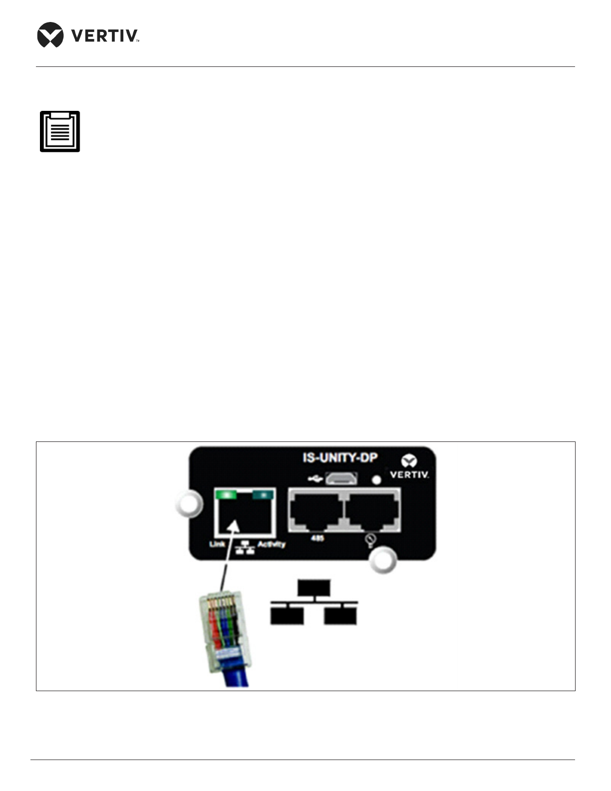
Vertiv | Liebert® PEX3™ Series Precision Air Conditioner | User Manual 88
Application of INTELLI SLOT
5.2. Commissioning Host Communication Component
Before commissioning you must access the SERVICE Menus’ of the iCOM control board to set S824 MON
ADD as ‘3’ S835 MON PORT as Vertiv and S843 BL CTRL as S+R in the “Network Setup.”
5.2.1. Assigning the Card’s IP Address
DHCP
Liebert IntelliSlot Unity card is factory-congured for DHCP. If you require a Static or Boot network
conguration, ensure to change the Boot Mode as described in Static IP. Connect a RJ-45 cable to the card and
it will receive an IP address from the DHCP server. Contact the DHCP administrator to obtain the IP address
using Liebert IntelliSlot Unity card’s MAC address. The MAC address is printed on the card faceplate.
If the DHCP administrator is not available or there is no way of determining the IP address assigned by the
DHCP server, use a computer with a direct Ethernet connection to Liebert IntelliSlot Unity card, and follow
the instructions to auto conguration IPv4 Address, conventions are described in Section 5.2.2- Connect an
Ethernet Cable - Connect an Ethernet Cable to access the card’s Web page and congure the card. To see
the card’s last DHCP- assigned IP address, click on the Unity Tab, then on the left side menu select Support >
Active Networking. The table of information shows the last IP address assigned by the DHCP server. The card
may retain that IP address when it reconnects to the DHCP network because most DHCP systems reuse the
same IP address for the same device.
Figure 5-2 IS-UNITY-DP Card Connection Port
Page 100
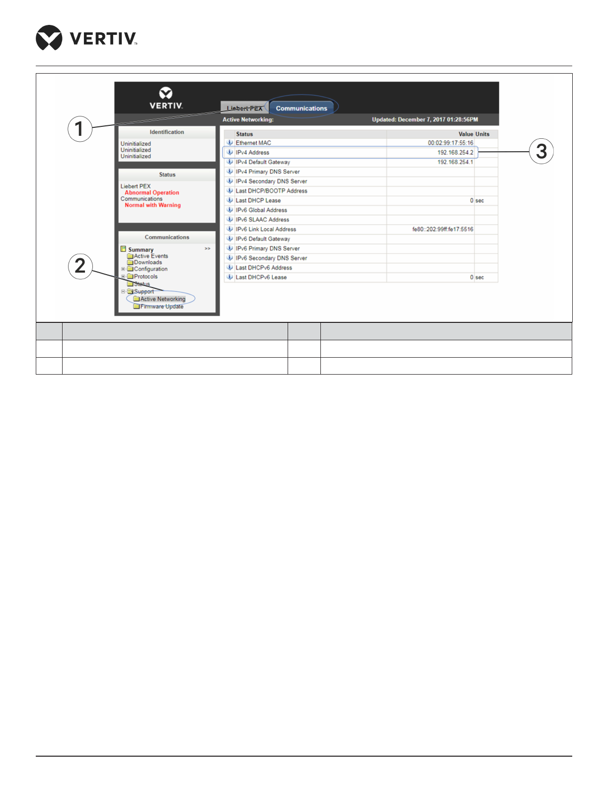
Vertiv | Liebert® PEX3™ Series Precision Air Conditioner | User Manual 89
Application of INTELLI SLOT
No. Description No. Description
1 Communication tab 3 IP address
2 Support > Active networking
Figure 5-3 Example of IS-UNITY-DP Card Web Page
Static IP
To assign a static IP address, use the Ethernet connection to congure the card. Proceed to Section 5.2.2.
Connect an Ethernet Cable.
5.2.2. Connect an Ethernet Cable
1. Connect the computer running on Microsoft Windows operating system (Microsoft Windows® XP with
SP2 [64-bit] or SP3 [32-bit] or later) to the card by plugging a network cable into the RJ-45 port on the
computer and Liebert IntelliSlot Unity card.
2. Auto-conguration, which is normally enabled on the computer running with Microsoft Windows operating
system will automatically negotiate the communication settings. This takes about one minute.
3. If the Ethernet adapter is used to attach the card and it does not show an auto-conguration IPv4 address,
then open a new Command Prompt and type ipcong/ renew and press ‘Enter’. This forces the computer to
acquire the auto-conguration IPv4 address.
4. When the computer has the auto-conguration IPv4 address, then open a browser window on the computer
and type 169.254.24.7 (the card’s default ‘Auto-conguration IPv4 Address’) in the URL address eld. The
card’s Web page appears.
 Loading...