

Page 1
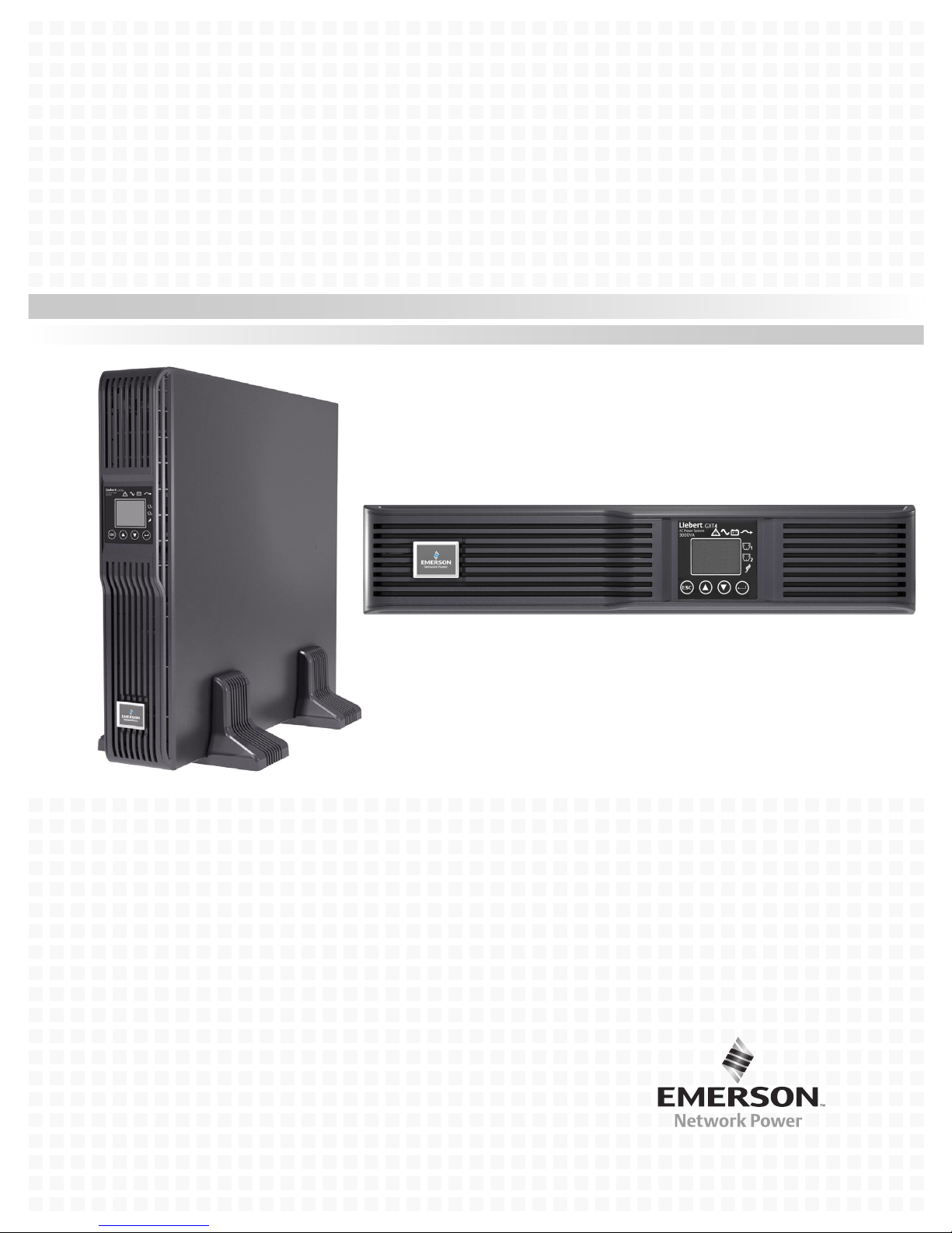
Liebert® GXT4™ UPS 230V 700VA-3000VA
User Manual
Page 2

Page 3

TABLE OF CONTENTS
IMPORTANT SAFETY PRECAUTIONS . . . . . . . . . . . . . . . . . . . . . . . . . . . . . . . . . . . . . . . . . . . . . . . .1
GLOSSARY OF SYMBOLS . . . . . . . . . . . . . . . . . . . . . . . . . . . . . . . . . . . . . . . . . . . . . . . . . . . . . . . .3
1.0 PRODUCT DESCRIPTION . . . . . . . . . . . . . . . . . . . . . . . . . . . . . . . . . . . . . . . . . . . . . . . . . . .4
1.1 Features . . . . . . . . . . . . . . . . . . . . . . . . . . . . . . . . . . . . . . . . . . . . . . . . . . . . . . . . . . . . . . . . . . . 4
1.2 Available Models . . . . . . . . . . . . . . . . . . . . . . . . . . . . . . . . . . . . . . . . . . . . . . . . . . . . . . . . . . . . 4
1.3 Appearance and Components . . . . . . . . . . . . . . . . . . . . . . . . . . . . . . . . . . . . . . . . . . . . . . . . . . 5
1.3.1 Appearance . . . . . . . . . . . . . . . . . . . . . . . . . . . . . . . . . . . . . . . . . . . . . . . . . . . . . . . . . . . . . . . . . . 5
1.3.2 Rear Panel Features. . . . . . . . . . . . . . . . . . . . . . . . . . . . . . . . . . . . . . . . . . . . . . . . . . . . . . . . . . . 5
1.4 Major Components . . . . . . . . . . . . . . . . . . . . . . . . . . . . . . . . . . . . . . . . . . . . . . . . . . . . . . . . . . . 7
1.5 Operating Mode . . . . . . . . . . . . . . . . . . . . . . . . . . . . . . . . . . . . . . . . . . . . . . . . . . . . . . . . . . . . . 8
1.5.1 Mains Mode. . . . . . . . . . . . . . . . . . . . . . . . . . . . . . . . . . . . . . . . . . . . . . . . . . . . . . . . . . . . . . . . . . 8
1.5.2 Manual Bypass Mode . . . . . . . . . . . . . . . . . . . . . . . . . . . . . . . . . . . . . . . . . . . . . . . . . . . . . . . . . . 8
1.5.3 Battery Mode . . . . . . . . . . . . . . . . . . . . . . . . . . . . . . . . . . . . . . . . . . . . . . . . . . . . . . . . . . . . . . . . 9
1.5.4 Battery Recharge Mode . . . . . . . . . . . . . . . . . . . . . . . . . . . . . . . . . . . . . . . . . . . . . . . . . . . . . . . . 9
1.5.5 Frequency Converter Mode . . . . . . . . . . . . . . . . . . . . . . . . . . . . . . . . . . . . . . . . . . . . . . . . . . . . . 9
1.5.6 Active ECO Mode . . . . . . . . . . . . . . . . . . . . . . . . . . . . . . . . . . . . . . . . . . . . . . . . . . . . . . . . . . . . . 9
2.0 INSTALLATION . . . . . . . . . . . . . . . . . . . . . . . . . . . . . . . . . . . . . . . . . . . . . . . . . . . . . . . . .10
2.1 Unpacking and Inspection . . . . . . . . . . . . . . . . . . . . . . . . . . . . . . . . . . . . . . . . . . . . . . . . . . . . 10
2.2 What’s Included . . . . . . . . . . . . . . . . . . . . . . . . . . . . . . . . . . . . . . . . . . . . . . . . . . . . . . . . . . . . 10
2.3 Preparation for Installation . . . . . . . . . . . . . . . . . . . . . . . . . . . . . . . . . . . . . . . . . . . . . . . . . . . 10
2.3.1 Installation Environment. . . . . . . . . . . . . . . . . . . . . . . . . . . . . . . . . . . . . . . . . . . . . . . . . . . . . . 10
2.4 Mechanical Installation . . . . . . . . . . . . . . . . . . . . . . . . . . . . . . . . . . . . . . . . . . . . . . . . . . . . . . 11
2.4.1 Tower Installation . . . . . . . . . . . . . . . . . . . . . . . . . . . . . . . . . . . . . . . . . . . . . . . . . . . . . . . . . . . 11
2.4.2 Rack Installation . . . . . . . . . . . . . . . . . . . . . . . . . . . . . . . . . . . . . . . . . . . . . . . . . . . . . . . . . . . . 12
2.5 Cable Connection . . . . . . . . . . . . . . . . . . . . . . . . . . . . . . . . . . . . . . . . . . . . . . . . . . . . . . . . . . . 12
2.5.1 Connecting to AC Mains and Loads . . . . . . . . . . . . . . . . . . . . . . . . . . . . . . . . . . . . . . . . . . . . . 12
2.5.2 Connecting Battery Cables . . . . . . . . . . . . . . . . . . . . . . . . . . . . . . . . . . . . . . . . . . . . . . . . . . . . 14
2.6 Connecting Communication Cables. . . . . . . . . . . . . . . . . . . . . . . . . . . . . . . . . . . . . . . . . . . . . 14
2.6.1 Connecting USB Communication Cables . . . . . . . . . . . . . . . . . . . . . . . . . . . . . . . . . . . . . . . . . 14
2.6.2 Installing the Optional Liebert
IntelliSlot® Card and Communication Cables . . . . . . . . . . . 14
3.0 OPERATION AND DISPLAY PANEL . . . . . . . . . . . . . . . . . . . . . . . . . . . . . . . . . . . . . . . . . . .15
3.1 LED Indicators . . . . . . . . . . . . . . . . . . . . . . . . . . . . . . . . . . . . . . . . . . . . . . . . . . . . . . . . . . . . . 15
3.2 Control Buttons . . . . . . . . . . . . . . . . . . . . . . . . . . . . . . . . . . . . . . . . . . . . . . . . . . . . . . . . . . . . 16
3.3 LCD . . . . . . . . . . . . . . . . . . . . . . . . . . . . . . . . . . . . . . . . . . . . . . . . . . . . . . . . . . . . . . . . . . . . . . 16
3.4 Menu Structure . . . . . . . . . . . . . . . . . . . . . . . . . . . . . . . . . . . . . . . . . . . . . . . . . . . . . . . . . . . . 17
3.4.1 Startup Screen . . . . . . . . . . . . . . . . . . . . . . . . . . . . . . . . . . . . . . . . . . . . . . . . . . . . . . . . . . . . . . 18
3.4.2 Default Screen . . . . . . . . . . . . . . . . . . . . . . . . . . . . . . . . . . . . . . . . . . . . . . . . . . . . . . . . . . . . . . 19
3.4.3 Main Menu Screen . . . . . . . . . . . . . . . . . . . . . . . . . . . . . . . . . . . . . . . . . . . . . . . . . . . . . . . . . . . 19
3.4.4 Prompt List . . . . . . . . . . . . . . . . . . . . . . . . . . . . . . . . . . . . . . . . . . . . . . . . . . . . . . . . . . . . . . . . . 29
3.4.5 Warning List . . . . . . . . . . . . . . . . . . . . . . . . . . . . . . . . . . . . . . . . . . . . . . . . . . . . . . . . . . . . . . . . 29
3.4.6 Fault List . . . . . . . . . . . . . . . . . . . . . . . . . . . . . . . . . . . . . . . . . . . . . . . . . . . . . . . . . . . . . . . . . . 30
4.0 OPERATION . . . . . . . . . . . . . . . . . . . . . . . . . . . . . . . . . . . . . . . . . . . . . . . . . . . . . . . . . . .31
i
Page 4

4.1 Startup Checklist for the Liebert GXT4 . . . . . . . . . . . . . . . . . . . . . . . . . . . . . . . . . . . . . . . . . 31
4.2 Starting the UPS . . . . . . . . . . . . . . . . . . . . . . . . . . . . . . . . . . . . . . . . . . . . . . . . . . . . . . . . . . . 31
4.3 Manual Battery Test . . . . . . . . . . . . . . . . . . . . . . . . . . . . . . . . . . . . . . . . . . . . . . . . . . . . . . . . 31
4.4 Manual Bypass . . . . . . . . . . . . . . . . . . . . . . . . . . . . . . . . . . . . . . . . . . . . . . . . . . . . . . . . . . . . . 31
4.5 Shut Down the Liebert GXT4 . . . . . . . . . . . . . . . . . . . . . . . . . . . . . . . . . . . . . . . . . . . . . . . . . 32
4.6 Disconnecting Input Power from the Liebert GXT4. . . . . . . . . . . . . . . . . . . . . . . . . . . . . . . . 32
5.0 COMMUNICATION . . . . . . . . . . . . . . . . . . . . . . . . . . . . . . . . . . . . . . . . . . . . . . . . . . . . . . . 33
5.1 Liebert IntelliSlot Communication Cards. . . . . . . . . . . . . . . . . . . . . . . . . . . . . . . . . . . . . . . . 33
5.1.1 Liebert MultiLink . . . . . . . . . . . . . . . . . . . . . . . . . . . . . . . . . . . . . . . . . . . . . . . . . . . . . . . . . . . . 33
5.2 USB Port Communication . . . . . . . . . . . . . . . . . . . . . . . . . . . . . . . . . . . . . . . . . . . . . . . . . . . . 34
5.2.1 Configuration Program . . . . . . . . . . . . . . . . . . . . . . . . . . . . . . . . . . . . . . . . . . . . . . . . . . . . . . . 34
5.3 RS-232 Port. . . . . . . . . . . . . . . . . . . . . . . . . . . . . . . . . . . . . . . . . . . . . . . . . . . . . . . . . . . . . . . . 35
5.4 Terminal Block Communication . . . . . . . . . . . . . . . . . . . . . . . . . . . . . . . . . . . . . . . . . . . . . . . 35
5.4.1 Any Mode Shutdown . . . . . . . . . . . . . . . . . . . . . . . . . . . . . . . . . . . . . . . . . . . . . . . . . . . . . . . . . 35
5.4.2 Battery Mode Shutdown . . . . . . . . . . . . . . . . . . . . . . . . . . . . . . . . . . . . . . . . . . . . . . . . . . . . . . 36
5.4.3 On Battery . . . . . . . . . . . . . . . . . . . . . . . . . . . . . . . . . . . . . . . . . . . . . . . . . . . . . . . . . . . . . . . . . 36
5.4.4 Low Battery . . . . . . . . . . . . . . . . . . . . . . . . . . . . . . . . . . . . . . . . . . . . . . . . . . . . . . . . . . . . . . . . 36
6.0 MAINTENANCE . . . . . . . . . . . . . . . . . . . . . . . . . . . . . . . . . . . . . . . . . . . . . . . . . . . . . . . . .37
6.1 Replacing the Internal Battery Pack. . . . . . . . . . . . . . . . . . . . . . . . . . . . . . . . . . . . . . . . . . . . 37
6.1.1 Battery Replacement Procedures . . . . . . . . . . . . . . . . . . . . . . . . . . . . . . . . . . . . . . . . . . . . . . . 38
6.2 Battery Charging . . . . . . . . . . . . . . . . . . . . . . . . . . . . . . . . . . . . . . . . . . . . . . . . . . . . . . . . . . . 39
6.3 Precautions . . . . . . . . . . . . . . . . . . . . . . . . . . . . . . . . . . . . . . . . . . . . . . . . . . . . . . . . . . . . . . . . 39
6.4 Checking UPS Status . . . . . . . . . . . . . . . . . . . . . . . . . . . . . . . . . . . . . . . . . . . . . . . . . . . . . . . . 39
7.0 TROUBLESHOOTING . . . . . . . . . . . . . . . . . . . . . . . . . . . . . . . . . . . . . . . . . . . . . . . . . . . . .40
7.1 UPS Symptoms. . . . . . . . . . . . . . . . . . . . . . . . . . . . . . . . . . . . . . . . . . . . . . . . . . . . . . . . . . . . . 40
7.1.1 Indicator and LCD . . . . . . . . . . . . . . . . . . . . . . . . . . . . . . . . . . . . . . . . . . . . . . . . . . . . . . . . . . . 40
7.1.2 Audible Alarm. . . . . . . . . . . . . . . . . . . . . . . . . . . . . . . . . . . . . . . . . . . . . . . . . . . . . . . . . . . . . . . 41
7.2 Troubleshooting . . . . . . . . . . . . . . . . . . . . . . . . . . . . . . . . . . . . . . . . . . . . . . . . . . . . . . . . . . . . 41
8.0 BATTERY CABINET . . . . . . . . . . . . . . . . . . . . . . . . . . . . . . . . . . . . . . . . . . . . . . . . . . . . . .42
9.0 SPECIFICATIONS. . . . . . . . . . . . . . . . . . . . . . . . . . . . . . . . . . . . . . . . . . . . . . . . . . . . . . . .43
9.1 Product Warranty Registration . . . . . . . . . . . . . . . . . . . . . . . . . . . . . . . . . . . . . . . . . . . . . . . . 48
9.2 Technical Support. . . . . . . . . . . . . . . . . . . . . . . . . . . . . . . . . . . . . . . . . . . . . . . . . . . . . . . . . . . 48
ii
Page 5

FIGURES
Figure 1 Liebert GXT4-700RT230 - GXT4-3000RT230 UPS. . . . . . . . . . . . . . . . . . . . . . . . . . . . . . . . . . . . . . 5
Figure 2 Rear components, Liebert GXT4 230V 700VA and 1000VA models . . . . . . . . . . . . . . . . . . . . . . . . 5
Figure 3 Rear components, Liebert GXT4 230V 1500VA models . . . . . . . . . . . . . . . . . . . . . . . . . . . . . . . . . . 6
Figure 4 Rear components, Liebert GXT4 230V 2000VA models . . . . . . . . . . . . . . . . . . . . . . . . . . . . . . . . . . 6
Figure 5 Rear components, Liebert GXT4 230V 3000VA models . . . . . . . . . . . . . . . . . . . . . . . . . . . . . . . . . . 6
Figure 6 Operating principle diagram . . . . . . . . . . . . . . . . . . . . . . . . . . . . . . . . . . . . . . . . . . . . . . . . . . . . . . . 7
Figure 7 Support bases . . . . . . . . . . . . . . . . . . . . . . . . . . . . . . . . . . . . . . . . . . . . . . . . . . . . . . . . . . . . . . . . . . 11
Figure 8 Remove the front plastic bezel cover . . . . . . . . . . . . . . . . . . . . . . . . . . . . . . . . . . . . . . . . . . . . . . . . 11
Figure 9 Tower installation . . . . . . . . . . . . . . . . . . . . . . . . . . . . . . . . . . . . . . . . . . . . . . . . . . . . . . . . . . . . . . . 12
Figure 10 Cable strain relief . . . . . . . . . . . . . . . . . . . . . . . . . . . . . . . . . . . . . . . . . . . . . . . . . . . . . . . . . . . . . . . 13
Figure 11 Battery cable attachment . . . . . . . . . . . . . . . . . . . . . . . . . . . . . . . . . . . . . . . . . . . . . . . . . . . . . . . . . 14
Figure 12 Operation and display panel . . . . . . . . . . . . . . . . . . . . . . . . . . . . . . . . . . . . . . . . . . . . . . . . . . . . . . 15
Figure 13 Menu structure . . . . . . . . . . . . . . . . . . . . . . . . . . . . . . . . . . . . . . . . . . . . . . . . . . . . . . . . . . . . . . . . . 17
Figure 14 Startup screen . . . . . . . . . . . . . . . . . . . . . . . . . . . . . . . . . . . . . . . . . . . . . . . . . . . . . . . . . . . . . . . . . . 18
Figure 15 Startup screens . . . . . . . . . . . . . . . . . . . . . . . . . . . . . . . . . . . . . . . . . . . . . . . . . . . . . . . . . . . . . . . . . 18
Figure 16 Starting and Start Successful screens . . . . . . . . . . . . . . . . . . . . . . . . . . . . . . . . . . . . . . . . . . . . . . . 18
Figure 17 Default screen . . . . . . . . . . . . . . . . . . . . . . . . . . . . . . . . . . . . . . . . . . . . . . . . . . . . . . . . . . . . . . . . . . 19
Figure 18 Main Menu screen. . . . . . . . . . . . . . . . . . . . . . . . . . . . . . . . . . . . . . . . . . . . . . . . . . . . . . . . . . . . . . . 19
Figure 19 Status screens . . . . . . . . . . . . . . . . . . . . . . . . . . . . . . . . . . . . . . . . . . . . . . . . . . . . . . . . . . . . . . . . . . 20
Figure 20 CONFIGURATION screen . . . . . . . . . . . . . . . . . . . . . . . . . . . . . . . . . . . . . . . . . . . . . . . . . . . . . . . . 20
Figure 21 UPS screens. . . . . . . . . . . . . . . . . . . . . . . . . . . . . . . . . . . . . . . . . . . . . . . . . . . . . . . . . . . . . . . . . . . . 21
Figure 22 Battery screen . . . . . . . . . . . . . . . . . . . . . . . . . . . . . . . . . . . . . . . . . . . . . . . . . . . . . . . . . . . . . . . . . . 21
Figure 23 ECO Mode screen . . . . . . . . . . . . . . . . . . . . . . . . . . . . . . . . . . . . . . . . . . . . . . . . . . . . . . . . . . . . . . . 22
Figure 24 Outlet1 screen . . . . . . . . . . . . . . . . . . . . . . . . . . . . . . . . . . . . . . . . . . . . . . . . . . . . . . . . . . . . . . . . . . 22
Figure 25 Outlet Control screen . . . . . . . . . . . . . . . . . . . . . . . . . . . . . . . . . . . . . . . . . . . . . . . . . . . . . . . . . . . . 23
Figure 26 Outlet Setting screen . . . . . . . . . . . . . . . . . . . . . . . . . . . . . . . . . . . . . . . . . . . . . . . . . . . . . . . . . . . . 23
Figure 27 Outlet2 setting screen. . . . . . . . . . . . . . . . . . . . . . . . . . . . . . . . . . . . . . . . . . . . . . . . . . . . . . . . . . . . 24
Figure 28 LCD screen . . . . . . . . . . . . . . . . . . . . . . . . . . . . . . . . . . . . . . . . . . . . . . . . . . . . . . . . . . . . . . . . . . . . 24
Figure 29 Language screen . . . . . . . . . . . . . . . . . . . . . . . . . . . . . . . . . . . . . . . . . . . . . . . . . . . . . . . . . . . . . . . . 24
Figure 30 Color screen . . . . . . . . . . . . . . . . . . . . . . . . . . . . . . . . . . . . . . . . . . . . . . . . . . . . . . . . . . . . . . . . . . . . 25
Figure 31 Factory Default screen . . . . . . . . . . . . . . . . . . . . . . . . . . . . . . . . . . . . . . . . . . . . . . . . . . . . . . . . . . . 25
Figure 32 Control screen . . . . . . . . . . . . . . . . . . . . . . . . . . . . . . . . . . . . . . . . . . . . . . . . . . . . . . . . . . . . . . . . . . 25
Figure 33 Turn UPS On or Off screen . . . . . . . . . . . . . . . . . . . . . . . . . . . . . . . . . . . . . . . . . . . . . . . . . . . . . . . 26
Figure 34 Alarm Control screen . . . . . . . . . . . . . . . . . . . . . . . . . . . . . . . . . . . . . . . . . . . . . . . . . . . . . . . . . . . . 26
Figure 35 Batt Test screen . . . . . . . . . . . . . . . . . . . . . . . . . . . . . . . . . . . . . . . . . . . . . . . . . . . . . . . . . . . . . . . . 26
Figure 36 Log screens . . . . . . . . . . . . . . . . . . . . . . . . . . . . . . . . . . . . . . . . . . . . . . . . . . . . . . . . . . . . . . . . . . . . 27
Figure 37 Clear Log screen . . . . . . . . . . . . . . . . . . . . . . . . . . . . . . . . . . . . . . . . . . . . . . . . . . . . . . . . . . . . . . . . 27
Figure 38 About screen . . . . . . . . . . . . . . . . . . . . . . . . . . . . . . . . . . . . . . . . . . . . . . . . . . . . . . . . . . . . . . . . . . . 27
Figure 39 Network screens . . . . . . . . . . . . . . . . . . . . . . . . . . . . . . . . . . . . . . . . . . . . . . . . . . . . . . . . . . . . . . . . 28
Figure 40 Terminal Block Communication pin layout. . . . . . . . . . . . . . . . . . . . . . . . . . . . . . . . . . . . . . . . . . . 35
Figure 41 Removing the front plastic bezel cover and battery door . . . . . . . . . . . . . . . . . . . . . . . . . . . . . . . . 38
Figure 42 Disconnecting the battery plug and battery connector (front view). . . . . . . . . . . . . . . . . . . . . . . . 38
Figure 43 Pulling out the battery . . . . . . . . . . . . . . . . . . . . . . . . . . . . . . . . . . . . . . . . . . . . . . . . . . . . . . . . . . . 38
Figure 44 Battery cabinet . . . . . . . . . . . . . . . . . . . . . . . . . . . . . . . . . . . . . . . . . . . . . . . . . . . . . . . . . . . . . . . . . 42
iii
Page 6

TABLES
Table 1 UPS models, power ratings . . . . . . . . . . . . . . . . . . . . . . . . . . . . . . . . . . . . . . . . . . . . . . . . . . . . . . . . 4
Table 2 Input circuit breaker specifications . . . . . . . . . . . . . . . . . . . . . . . . . . . . . . . . . . . . . . . . . . . . . . . . . 12
Table 3 Type of cord . . . . . . . . . . . . . . . . . . . . . . . . . . . . . . . . . . . . . . . . . . . . . . . . . . . . . . . . . . . . . . . . . . . . 13
Table 4 Ratings of cord. . . . . . . . . . . . . . . . . . . . . . . . . . . . . . . . . . . . . . . . . . . . . . . . . . . . . . . . . . . . . . . . . . 13
Table 5 LED indicators . . . . . . . . . . . . . . . . . . . . . . . . . . . . . . . . . . . . . . . . . . . . . . . . . . . . . . . . . . . . . . . . . 15
Table 6 Control buttons . . . . . . . . . . . . . . . . . . . . . . . . . . . . . . . . . . . . . . . . . . . . . . . . . . . . . . . . . . . . . . . . . 16
Table 7 Prompts and meanings . . . . . . . . . . . . . . . . . . . . . . . . . . . . . . . . . . . . . . . . . . . . . . . . . . . . . . . . . . . 29
Table 8 Warning list. . . . . . . . . . . . . . . . . . . . . . . . . . . . . . . . . . . . . . . . . . . . . . . . . . . . . . . . . . . . . . . . . . . . 29
Table 9 Fault list . . . . . . . . . . . . . . . . . . . . . . . . . . . . . . . . . . . . . . . . . . . . . . . . . . . . . . . . . . . . . . . . . . . . . . 30
Table 10 Output voltage option, all models . . . . . . . . . . . . . . . . . . . . . . . . . . . . . . . . . . . . . . . . . . . . . . . . . . 34
Table 11 Replacement battery pack model numbers . . . . . . . . . . . . . . . . . . . . . . . . . . . . . . . . . . . . . . . . . . . 37
Table 12 Description of the displayed fault . . . . . . . . . . . . . . . . . . . . . . . . . . . . . . . . . . . . . . . . . . . . . . . . . . 40
Table 13 Audible alarm description . . . . . . . . . . . . . . . . . . . . . . . . . . . . . . . . . . . . . . . . . . . . . . . . . . . . . . . . 41
Table 14 Troubleshooting table . . . . . . . . . . . . . . . . . . . . . . . . . . . . . . . . . . . . . . . . . . . . . . . . . . . . . . . . . . . . 41
Table 15 Specifications of GXT4-700RT230/230E and GXT4-1000RT230/230E UPS . . . . . . . . . . . . . . . . . 43
Table 16 Specifications of the Liebert GXT4-1500RT230/230E, GXT4-2000RT230/230E and
GXT-3000RT230/230E . . . . . . . . . . . . . . . . . . . . . . . . . . . . . . . . . . . . . . . . . . . . . . . . . . . . . . . . . . . 44
Table 17 Operating temperature parameters. . . . . . . . . . . . . . . . . . . . . . . . . . . . . . . . . . . . . . . . . . . . . . . . . 45
Table 18 Battery cabinet specifications . . . . . . . . . . . . . . . . . . . . . . . . . . . . . . . . . . . . . . . . . . . . . . . . . . . . . 45
Table 19 Battery run times . . . . . . . . . . . . . . . . . . . . . . . . . . . . . . . . . . . . . . . . . . . . . . . . . . . . . . . . . . . . . . . 46
iv
Page 7

IMPORTANT SAFETY PRECAUTIONS
!
!
WARNING
Risk of electric shock. Can cause equipment damage, injury or death.
Observe all cautions and warnings in this manual. Failure to do so may result in serious
injury or death.
Refer all UPS and battery service to properly trained and qualified service personnel. Do not
attempt to service this product yourself.
Opening or removing the cover may expose you to lethal voltages within this unit even when
it is apparently not operating and the input wiring is disconnected from the electrical source.
Never work alone.
SAVE THESE INSTRUCTIONS
This manual contains important safety instructions that must be followed during the installation and
maintenance of the UPS and batteries. Read this manual thoroughly before attempting to install or
operate this UPS.
UPS Safety Notes
The UPS contains no user-serviceable parts except the internal battery pack. Do not remove the
cover. Removing the cover may result in electric shock and will invalidate any implied warranty.
The UPS has an internal battery, so the output receptacles of the UPS may carry live voltage even if
the UPS is not connected to mains input power.
Before moving or rewiring the UPS, disconnect mains input power and the battery and make sure
that the UPS is completely shut down. Otherwise, the output terminal may carry live voltage,
presenting an electric shock hazard.
To ensure human safety and normal UPS operation, the UPS must be properly grounded before use.
When the UPS is connected to an IT power distribution system, the short-circuit protection device
must be installed on the neutral line.
Install and use the UPS in the following environments:
• Temperature: 0°C to 40°C (32 - 104°F); relative humidity: 0% to 95%, non-condensing)
• Out of direct sunlight
• Away from heat source
• Stable surface, not subject to vibrations or shocks
• Away from dust and other particulates
• Away from corrosive substances, salts and flammable gases
Keep the air inlet and outlet of the UPS unobstructed. Poor ventilation will increase the UPS internal
temperature and can shorten the life of the UPS and its batteries.
Keep liquid and other foreign objects away from the UPS.
This UPS is not intended for use with life support and other designated critical devices. Maximum
load must not exceed that shown on the UPS rating label. This UPS is designed for data processing
equipment. If uncertain, consult your local dealer or Emerson Network Power
®
representative.
Battery Safety
WARNING
Risk of electric shock and explosion. Can cause equipment damage, injury and death.
Do not dispose of the battery in a fire. The battery may explode.
Do not open or damage the battery. Released electrolyte is toxic and is harmful to skin and
eyes. If electrolyte comes into contact with the skin, wash the affected area immediately with
plenty of clean water and get medical attention.
1Liebert
®
GXT4
™
Page 8
!
WARNING
Risk of electric shock. Can cause equipment damage, injury and death.
A battery can present a risk of electrical shock and high short-circuit current. The following
precautions should be observed when working on batteries:
• Remove watches, rings and other metal objects.
• Use tools with insulated handles.
• Wear rubber gloves and boots.
• Do not lay tools or metal parts on top of batteries.
• Disconnect charging source prior to connecting or disconnecting battery terminals.
• Determine if the battery is inadvertently grounded. If it is inadvertently grounded, remove
the source of the ground. Contact with any part of a grounded battery can result in
electrical shock. The likelihood of such shock will be reduced if grounds are removed during
installation and maintenance (applicable to a UPS and a remote battery supply not having
a grounded supply circuit).
ELECTROMAGNETIC COMPATIBILITY—The Liebert GXT4 series complies with the limits for a
Class A digital device. Operating this device in a residential area is likely to cause harmful
interference that users must correct at their own expense.
The Liebert GXT4 series complies with the requirements of EMC Directive 2004/108/EC and the
published technical standards. Continued compliance requires installation in accordance with these
instructions and use of accessories approved by Emerson
Information for the Protection of the Environment
UPS SERVICING—This UPS makes use of components dangerous for the environment (electronic
cards, electronic components). The components removed must be taken to specialized collection and
disposal centers.
®
.
NOTICE TO EUROPEAN UNION CUSTOMERS: DISPOSAL OF OLD APPLIANCES—This
product has been supplied from an environmentally aware manufacturer that complies with the
Waste Electrical and Electronic Equipment (WEEE) Directive 2002/96/CE.
The “crossed-out wheelie bin” symbol at right is placed on this product to
encourage you to recycle wherever possible. Please be environmentally
responsible and recycle this product through your recycling facility at its end
of life. Do not dispose of this product as unsorted municipal waste. Follow
local municipal waste ordinances for proper disposal provisions to reduce the
environmental impact of waste electrical and electronic equipment (WEEE).
For information regarding the scrapping of this equipment, please browse
http://www.eu.emersonnetworkpower.com (“Products session” or
“Contact us” session) or call our worldwide technical support.
• Toll Free: 00 80011554499
• Toll Number Based in Italy: +39 0298250222
Liebert® GXT4
™
2
Page 9
GLOSSARY OF SYMBOLS
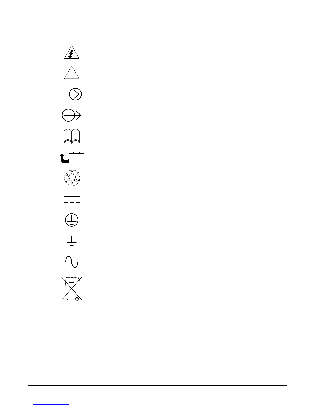
!
PbH2SO4
-
+
R
Risk of electrical shock
Indicates a warning or a caution followed by important instructions
AC input
AC output
i
Requests the user to consult the manual
Indicates the unit contains a valve-regulated lead acid battery
Recycle
DC voltage
Equipment grounding conductor
Bonded to ground
AC voltage
WEEE
3Liebert
®
GXT4
™
Page 10
1.0 PRODUCT DESCRIPTION
The Liebert GXT4 is a compact, online uninterruptible power system (UPS) that continuously
conditions and regulates its output voltage. The UPS is designed to supply microcomputers and other
sensitive electronic equipment with clean sine wave input power, 700VA to 3000VA at 230V.
Upon generation, AC power is clean and stable. However, during transmission and distribution it is
subject to voltage sags, spikes and complete failure that may interrupt computer operations, cause
data loss and damage equipment.
The Liebert GXT4 protects equipment from these disturbances. The Liebert GXT4 continuously
charges its batteries from the mains, enabling it to supply power to connected loads, even when the
mains fail.
This section describes the UPS, its features, models, appearance and components, operating
principles and operating mode.
1.1 Features
The UPS includes these features:
• Intelligent battery management to extend battery life
• LCD for user-friendly operation and local monitoring and configuration of operational parameters
• Flexible network management with Liebert MultiLink
• Fan fault self-inspection and automated diagnostic function
• Intelligent fan operation, automatically changing rotation speed depending on system
requirements, to decrease power consumption and noise
• Input circuit breaker to ease recovery from overloads
• CE mark and safety approval from CE
• Communication options: USB port, Liebert IntelliSlot
• Dry contacts for remote monitoring
• Input power factor greater than 0.99
• Output voltage selection function
Product Description
®
software
®
port and terminal block communication
1.2 Available Models
Available models of the UPS are listed in Table 1:
Table 1 UPS models, power ratings
Model Nominal Power Rating
GXT4-700RT230
GXT4-700RT230E
GXT4-1000RT230
GXT4-1000RT230E
GXT4-1500RT230
GXT4-1500RT230E
GXT4-2000RT230
GXT4-2000RT230E
GXT4-3000RT230
GXT4-3000RT230E
700VA/630W
1000VA/900W
1500VA/1350W
2000VA/1800W
3000VA/2700W
Liebert® GXT4
™
4
Page 11
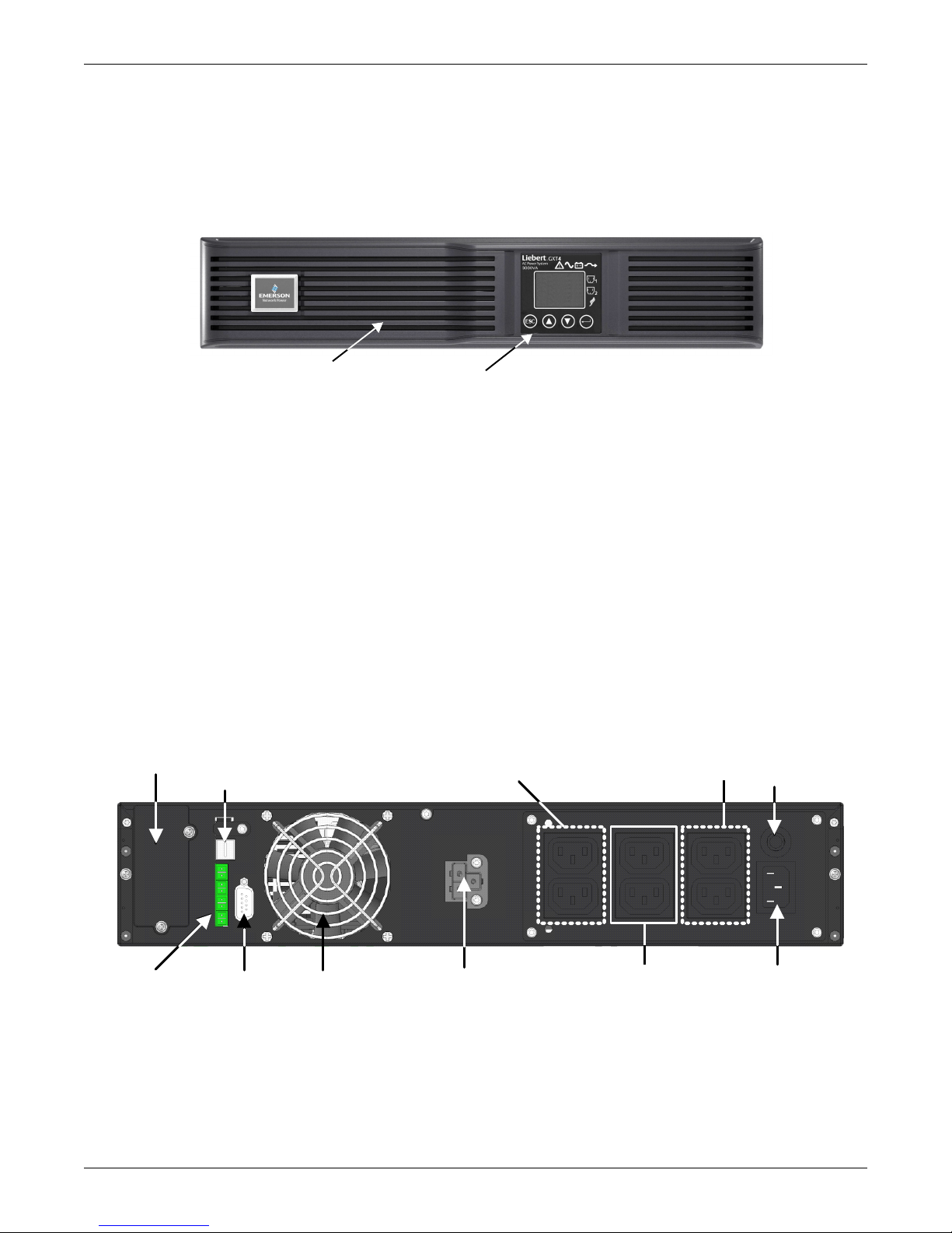
1.3 Appearance and Components
Operation and Display Panel
Ventilation Slots
Terminal Block
RS232
Port
Liebert IntelliSlot Port
USB Port
Cooling
Fan
Input Circuit
Breaker
External Battery
Connector
General Output
Receptacle, 2
Programmable Output
Receptacle #2, 2
Programmable Output
Receptacle #1 - 2
Input Receptacle
1.3.1 Appearance
The Liebert GXT4 rack/tower models in various power ratings have the same general appearance,
controls and features (see Figure 1). The various rack/tower models differ largely in the type of
receptacles each has.
Figure 1 Liebert GXT4-700RT230 - GXT4-3000RT230 UPS
1.3.2 Rear Panel Features
The rear panel of the Liebert GXT4 has these features:
• Liebert IntelliSlot
•USB port
• Input Circuit Breaker
•Input Receptacle
• General Output Receptacles
• Programmable Output Receptacles
• Cable Strain Relief Attachment Hole
• External Battery Connector
• Cooling Fan
• RS-232 port
• Terminal Block Communication
• Output Circuit Breakers (only on GXT4-3000RT230/230E models)
Figure 2 Rear components, Liebert GXT4 230V 700VA and 1000VA models
®
Port
Product Description
5Liebert
®
GXT4
™
Page 12
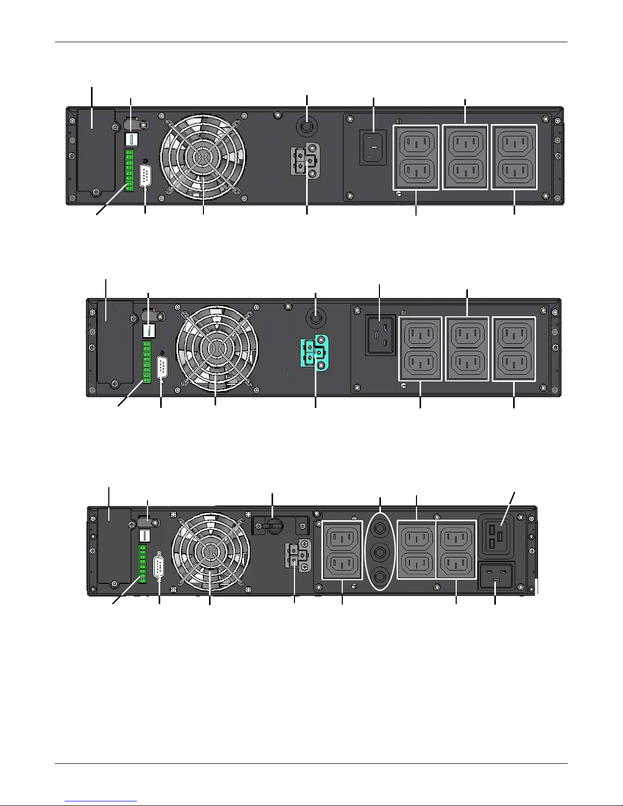
Figure 3 Rear components, Liebert GXT4 230V 1500VA models
Dry Contacts
RS232
Port
Liebert IntelliSlot Port
USB Port
Fan
Input Circuit Breaker
External Battery
Connector
Outlet 1 Receptacles
(Programmable )
C14
Input
Outlet2 Receptacles
Programmable
General
Output
Liebert IntelliSlot Port
USB Port
Cooling
Fan
Input Circuit Breaker
C20 Input
Terminal Block
Communications
RS232
Port
External Battery
Connector
Programmable
Outlets #2
Programmable
Outlets #1
Non-Programmable
Outlets
Output Circuit
Breakers
C20 Input
Receptacle
Liebert IntelliSlot Port
USB Port
Cooling
Fan
Input Circuit Breaker
RS232
Port
External Battery
Connector
Non-Programmable
Outlet
General
Output
Terminal Block
Communications
Programmable
Outlets #2
Programmable
Outlets #1
Figure 4 Rear components, Liebert GXT4 230V 2000VA models
Product Description
Figure 5 Rear components, Liebert GXT4 230V 3000VA models
Liebert® GXT4
™
6
Page 13
1.4 Major Components
TVSS
EMI/RFI
Input
Filter
EMI/RFI
Output
Filter
Dynamic
Bypass
L
G
N
N
G
L
Programmable
Outlet Group 1
General
Outlet Group
Programmable
Outlet Group 2
General Outlet
(3000 VA Only)
Inverter
Battery
Charger
Battery
Rectifier/PFC
DC-DC
Converter
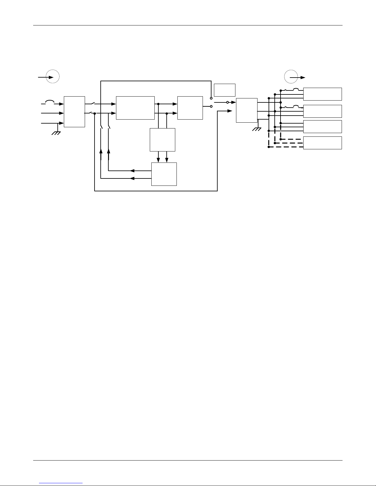
The operating principle of the UPS is shown in Figure 6.
Figure 6 Operating principle diagram
Product Description
The UPS is composed of mains input, TVSS and EMI/RFI filters, rectifier/PFC, inverter, battery
charger, DC-to-DC converter, battery, dynamic bypass and UPS output.
Transient Voltage Surge Suppression (TVSS) and EMI/RFI Filters
The Liebert GXT4 has surge protection and filters that protect the connected load from power surges
and sags, electromagnetic interference (EMI) and radio frequency interference (RFI). These features
can minimize any surges or interference present in the mains power. The filters also prevent surges
or interference generated by the UPS from adversely affecting other devices connected on the same
branch as the UPS.
Rectifier/Power Factor Correction (PFC) Circuit
In normal operation, the Liebert GXT4’s rectifier/power factor correction (PFC) circuit converts mains
power to regulated DC power for use by the inverter while ensuring that the wave shape of the input
current used by the UPS is near ideal. Extracting this sine wave input current achieves two
objectives:
• Efficient power use by the UPS
• Reduced reflected harmonics
This results in cleaner power being available to other devices in the building that are not protected by
the UPS.
Inverter
In normal operation, the Liebert GXT4’s inverter utilizes the DC output of the PFC circuit to produce
precise, regulated sine wave AC power. When mains power fails, the inverter receives DC power from
the battery through the DC-to DC converter. In either operation mode, the UPS inverter is online,
continuously generating clean, precise, regulated AC output power.
Battery Charger
The battery charger utilizes energy from the mains power and precisely regulates it to continuously
float charge the batteries. The batteries are being charged whenever the Liebert GXT4 is plugged in,
even when the UPS is not turned On.
7Liebert
®
GXT4
™
Page 14

DC-to-DC Converter
The DC-to-DC converter raises the DC voltage from the battery to the optimum operating voltage for
the inverter. This allows the inverter to operate continuously at its optimum efficiency and voltage,
increasing reliability.
Battery
The Liebert GXT4 utilizes valve-regulated, nonspillable, lead acid batteries. To maintain battery
design life, operate the Liebert GXT4 in an ambient temperature of 0°C to 25°C (32°F to 77°F).
Optional external battery cabinets are available to extend battery run times.
Dynamic Bypass
The Liebert GXT4 provides an alternate path for mains power to the connected loads in the unlikely
event of a UPS malfunction. Should the Liebert GXT4 have an overload, overtemperature, or UPS
failure condition, the UPS automatically transfers the connected loads to bypass.
NOTE
The bypass power path does not protect the connected loads from disturbances on the mains.
1.5 Operating Mode
The UPS operation modes include the following: Mains (AC) Mode, Bypass Mode, Battery Mode,
Battery Recharge Mode, Active ECO Mode and Frequency Converter Mode.
Product Description
Refer to 3.0 - Operation and Display Panel for details about the operating mode indicators and
control buttons.
1.5.1 Mains Mode
During Mains Mode, the mains provides input power to the Liebert GXT4. The filters, PFC circuit
and inverter process this power to provide high-quality sine wave power to connected loads. The UPS
maintains the batteries in a fully charged state.
1.5.2 Manual Bypass Mode
Manual Bypass Mode occurs when the unit is manually placed in internal bypass by navigating the
LCD display menu to select 3 Control > 1 Turn On & Off > Turn UPS Bypass. Bypass operation is
indicated by an audible alarm and illuminated amber bypass indicator. (If other indicators are
illuminated, refer to 7.0 - Troubleshooting). During Bypass Mode, mains power bypasses the
inverter and provides energy to the connected load.
NOTICE
Risk of loss of power to the connected load. Can cause equipment damage.
Turning Off the UPS in Bypass Mode will result in loss of output power to the connected load.
Liebert® GXT4
™
8
Page 15
1.5.3 Battery Mode
!
The Liebert GXT4 enters Battery Mode when mains power fails or is outside acceptable limits. The
battery system supplies power through the DC-to-DC converter to the inverter to generate clean AC
power for the connected loads.
When the Liebert GXT4 enters Battery Mode, the UPS sounds a half-second beep at 10-second
intervals. When approximately 2 minutes of run time remains, the beeps sound every 5 seconds to
warn that the battery is getting low (this Low Battery Warning is user-configurable).
In Battery Mode, the battery indicator will illuminate and the LCD will show the prompt Silence
Alarm and choices of Yes and No. The default is No. Press either the Up or Down arrow button to
select Yes, then press the Enter button to silence the alarm.
Once the alarm prompt has been acknowledged, the UPS will display the estimated battery run time
and battery capacity. Refer to 7.0 - Troubleshooting. For approximate battery run times, refer to
Table 17.
NOTICE
Risk of loss of power to the connected load. Can cause equipment damage.
Turning Off the Liebert GXT4 when it is in Battery Mode will result in loss of output power to
the connected load.
If the UPS is turned Off manually, it must be manually restarted after mains power returns.
If the UPS is turned Off by a communication signal or because the batteries are depleted, it
will operate as set in the configuration program for Auto-Restart (Refer to 5.2.1 -
Configuration Program).
Product Description
1.5.4 Battery Recharge Mode
Once mains power is applied to the Liebert GXT4, the Battery Charger begins charging the batteries.
1.5.5 Frequency Converter Mode
All models of the Liebert GXT4 are capable of frequency conversion. Frequency Conversion Mode can
be selected using the configuration program. Allowable frequency operating modes include:
• Auto Sensing - 50Hz or 60Hz – Bypass Enabled
• Auto Sensing - 50Hz or 60Hz – Bypass Disabled
• Frequency Converter - 50Hz – Bypass Disabled
• Frequency Converter - 60Hz – Bypass Disabled
NOTE
The default for all models of the Liebert GXT4 is “Auto Sensing - 50Hz or 60Hz – Bypass
Enabled.”
CAUTION
Risk of electric shock. Can cause injury or death.
Never touch the AC input receptacle while the UPS is operating. Voltage may still be present
even when the AC input indicator is Off.
1.5.6 Active ECO Mode
All Liebert GXT4 models can operate in Active ECO Mode. In this mode, the connected equipment is
powered through the bypass path to increase efficiency, reducing the electrical costs.
Active ECO mode keeps the rectifier and inverter operating, allowing the inverter to remain
synchronized to bypass. This synchronization allows the transfer of the connected equipment to UPS
inverter power almost seamlessly if bypass power falls outside the user-set limits. Once bypass power
returns within the acceptable parameters, the UPS will return to Active ECO Mode operation.
The default setting is Active ECO Mode Off.
9Liebert
®
GXT4
™
Page 16

2.0 INSTALLATION
2.1 Unpacking and Inspection
Unpack the UPS and conduct the following checks:
• Inspect the UPS for shipping damage. If any shipping damage is found, report it to the carrier and
your local dealer or Emerson
• Check the accessories against the delivery list. If there is any discrepancy, contact your local
dealer or your Emerson representative immediately.
2.2 What’s Included
• Terminal Block Communication Terminals
• Compact Disk with:
• Liebert MultiLink
• Configuration Program
• User Manual
• USB Cable—one, 1.2m (3.9 ft.) long
• RS-232 Cable—one, 2m (6-1/2 ft) long
• Cable Strain Relief—two pieces
• Rack mounting hardware, including screws, handles and mounting rail kit (not included with “E”
models)
• Plastic tower stand sets—two (four pieces)
• Warnings, Safety Instructions booklet and WEEE recycling sheet (ISO 14001 compliance)
®
Shutdown Software
®
representative immediately.
Installation
With 700VA - 1500VA Units:
• 10A IEC C13 C14 Output Cable—two, 2m (6-1/2 ft.) long
• CEE 7/7 (Schuko) to IEC C13 input cord—one, 2.5m (8-1/2 ft.) long (not included with “E” models)
• BS 1363 (UK) to IEC C13 input cord—one, 2.5m (8-1/2 ft.) long (not included with E models)
• Australian type A to SAA input cord—one (except “E” models)
With 2000VA - 3000VA Units:
• 10A IEC C13 C14 Output Cable—three, 2m (6-1/2 ft.) long
• CEE 7/7 (Schuko) to IEC C20 Input Cable—one, 2.5m (8-1/5 ft.) long (not included with “E”
models)
• BS1363 (UK) to IEC C20 Input Cable—one, 2.5m (8-1/5 ft.) long (not included with “E” models)
• Australian type A to SAA input cord—one (not included with “E” models)
NOTE
The GXT4 External Battery Cabinet shipping package includes one battery cabinet, two spacers
for tower configuration and one DC power cable and rack mounting hardware, including
screws, handles and mounting rail kit (not included with “E”) models.
2.3 Preparation for Installation
2.3.1 Installation Environment
• Install the UPS indoors in a controlled environment where it cannot be accidentally turned Off.
The installation environment should meet the specifications in 9.0 - Specifications.
• Place the UPS in an area where airflow around the unit is unrestricted and away from water,
flammable liquids, gases, corrosives and conductive contaminants. Avoid direct sunlight.
NOTE
Operating the Liebert GXT4 in temperatures above 25°C (77°F) reduces battery life.
Liebert® GXT4
™
10
Page 17
Installation Clearances
Support Bases
Spacers
Connectors
Front Plastic
Bezel Cover
Operation and Display Panel
Rotated Clockwise 90 Degrees
Maintain a clearance of at least 100mm (4 inches) in the front and rear of the Liebert GXT4. Do not
obstruct the air inlets on the front panel or rear panel of the UPS—blocking the air inlets reduces
ventilation and heat dissipation, shortening the service life of the Liebert GXT4.
2.4 Mechanical Installation
The Liebert GXT4 may be installed as a tower or in a rack, depending on space and use
considerations. The Liebert GXT4 may be used alone, as a single UPS, or with up to six battery
cabinets.
NOTE
When installing the UPS or making input and output connections, comply with all relevant
safety codes and standards.
2.4.1 Tower Installation
To install the Liebert GXT4 as a tower:
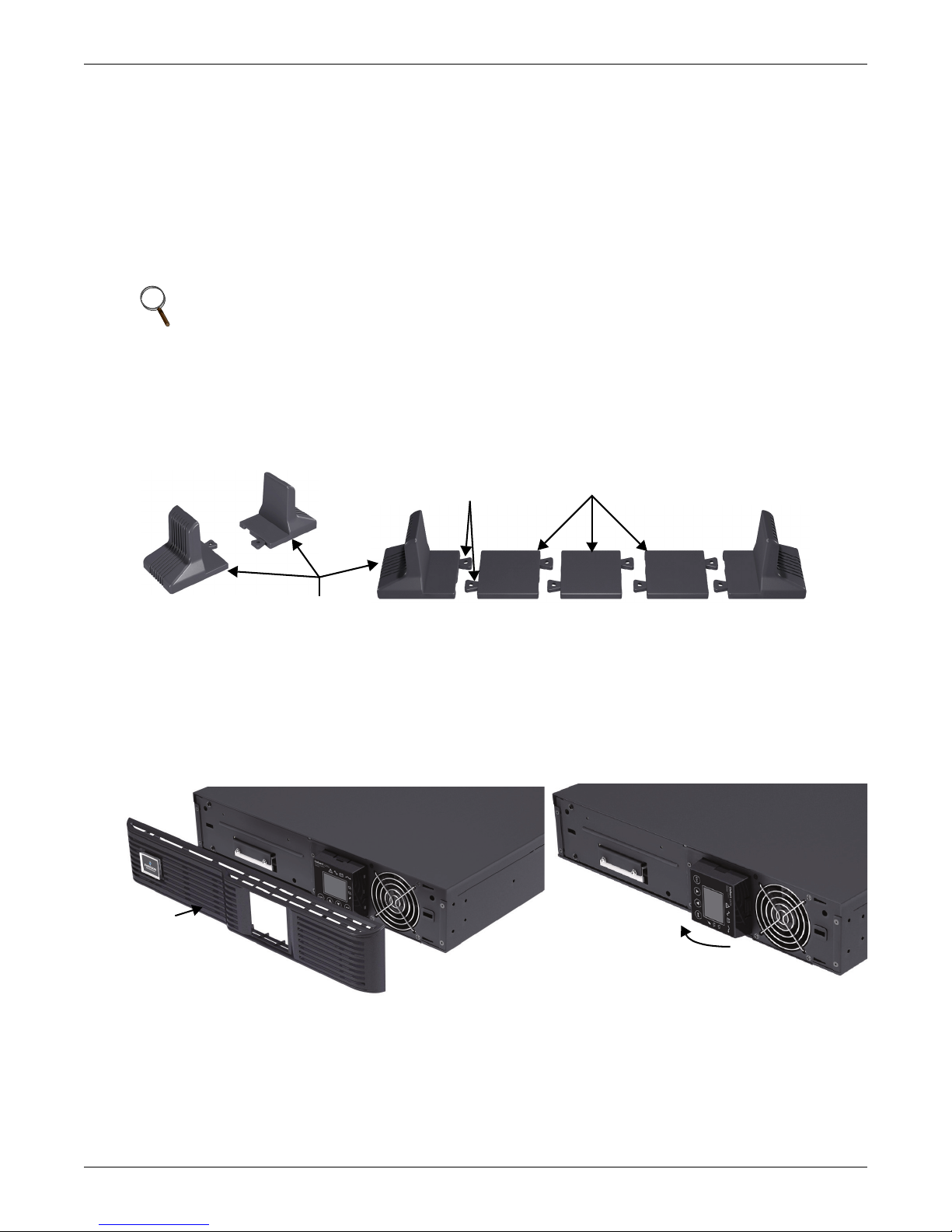
1. Take the support bases from the accessories package (see Figure 7).
Figure 7 Support bases
Installation
2. If optional Liebert external battery cabinets will be connected to the Liebert GXT4, take out the
spacers delivered with the battery cabinet.
3. Connect the spacers and the support bases as shown in Figure 7. Each Liebert GXT4 needs two
assembled support bases, one in the front and one in the rear.
4. Adjust the direction of the operation and display panel and logo on the Liebert GXT4.
a. Remove the front plastic bezel cover (see Figure 8).
Figure 8 Remove the front plastic bezel cover
b. Pull the operation and display panel, rotate it 90 degrees clockwise and snap it back into
position (see Figure 8).
c. Pull the logo on the front plastic bezel cover, rotate it 90 degrees clockwise and snap it back
into position. The rotated front plastic bezel cover is shown in Figure 9.
d. Replace the front plastic bezel cover on the Liebert GXT4. At this point, the UPS operation
and display panel and logo have been rotated 90 degrees clockwise, which provides upright
viewing for users.
11 Liebert® GXT4
™
Page 18
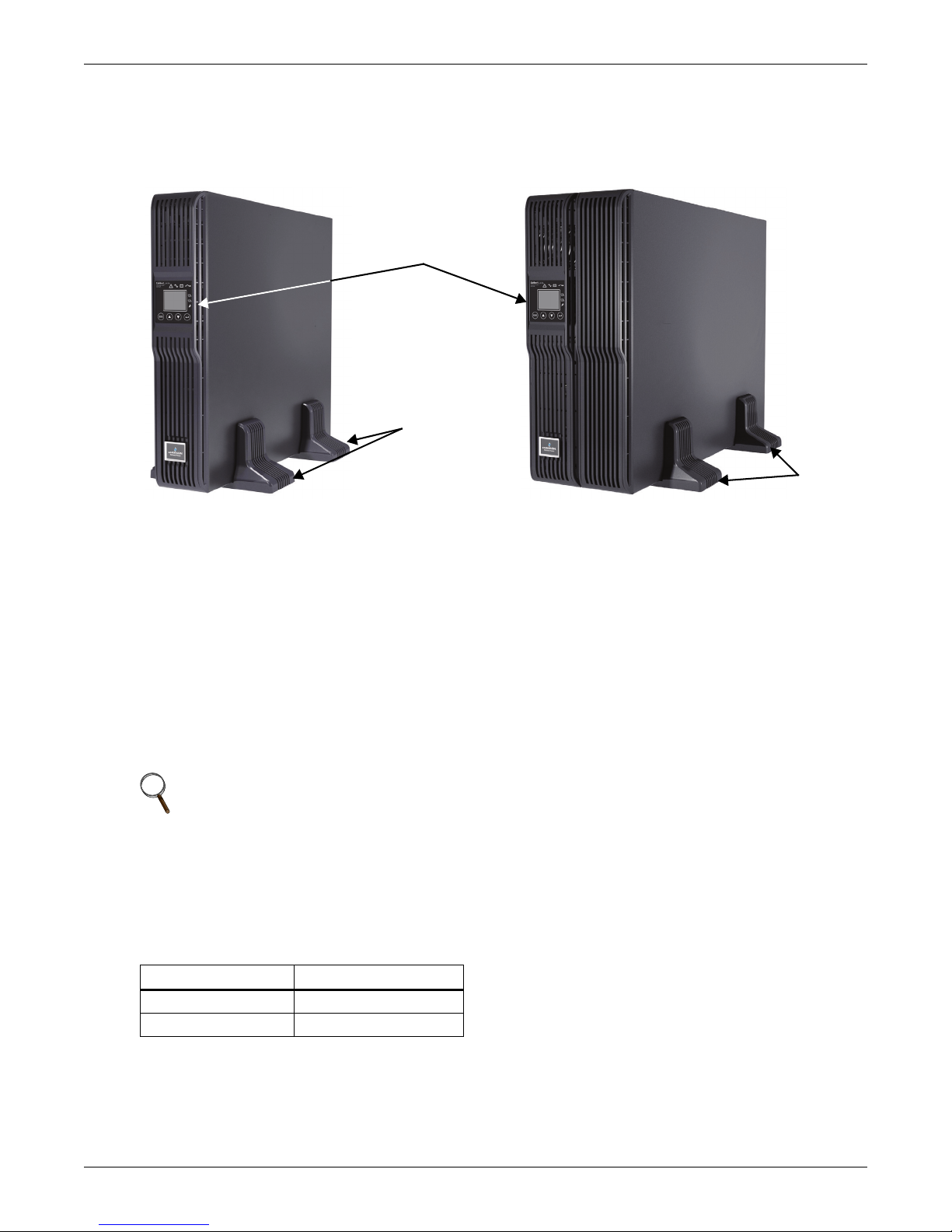
5. Place the Liebert GXT4 and any battery cabinets on the support bases. Each Liebert GXT4 needs
Operation and
Display Panel
Rotated for
Tower Operation
Support
Bases
Support
Bases
Liebert GXT4 UPS
Liebert GXT4 UPS and
External Battery Cabinet
four support bases, as shown in Figure 9.
Figure 9 Tower installation
Installation
2.4.2 Rack Installation
The Liebert GXT4 UPS and external battery cabinets (EBC), when installed in a rack enclosure, must
be supported by a shelf or rack-mount rails. The Liebert GXT4 UPS and EBC units ship with all
required hardware to allow rack-mount installation (not included with “E” models). Because different
rack-mount options install differently, refer to the installation instructions provided with the rack
mount kit being used.
2.5 Cable Connection
The Liebert GXT4 rear panel has an input receptacle and output receptacles. Refer to 1.3.2 - Rear
Panel Features for details. The battery cables are supplied with the battery cabinet.
2.5.1 Connecting to AC Mains and Loads
NOTE
Ensure that all the loads are turned Off.
Prepare an input power supply that is properly protected by a circuit breaker in accordance
with national and local electrical codes. The wall receptacle must be grounded.
®
recommends installing an upstream circuit breaker of the same or higher rating as
The specification of input circuit breaker on the rear panel of the UPS is given in Table 2.
Table 2 Input circuit breaker specifications
700-1500 VA Models 10A
2000-3000VA Models 16A
Emerson
the Liebert GXT4’s input circuit breaker.
Unit Rating Circuit Breaker Rating
Liebert® GXT4
™
12
Page 19
Installation
Hold the cable
Insert into the provided hole
to secure the line buckle
For North America Installations
Detachable Power Supply Cord Not Provided. Power Supply Cord Selection (for units which power
supply cord not furnished with) - Use UL Listed detachable power supply cord, three conductors,
minimum 4.5 ft. (1.5m), maximum 14.8 ft. (4.5m) long. Types SP-2, SP-3, SV and similar cords may be
provided if the cord is not long. Refer to Tables 3 and 4 for details.
Table 3 Type of cord
UPS Model Type of Cord
GXT4-700RT230, GXT4-700RT230E
GXT4-1000RT230, GXT4-1000RT230E
GXT4-3000RT230, GXT4-3000RT230E
SVE, SVO, SVOO, SVT, SVTO, SVTOO, SPE-2, SPT-2, NISP-2,
NISPE-2, NISPT-2, SPE-3, SPT-3, SJ, SJE, SJO, SJOO, SJT,
SJTO, SJTOO, S, SE, SO, SOO, ST, STO, STOO
Table 4 Ratings of cord
UPS Model
GXT4-3000RT230
GXT4-3000RT230E
GXT4-700RT230
GXT4-700RT230E
GXT4-1000RT230
GXT4-1000RT230E
Minimum Wire Gauge Minimum Cord Ratings Attachment Plug Ratings
12 AWG/3C 250 V, 105
16 AWG/3C 250 V, 105
o
C, VW-1 20 A, +250V (NEMA L6-20P)
o
C, VW-1 15 A, +250V (NEMA L6-15P)
Liebert GXT4 models 700-1500VA and 2000VA have three groups of outlets as shown in Figures 2, 3
and 5. One group is always On; the other two groups may be controlled with either programmed
responses or over an SNMP network. The 3000VA GXT4 UPS has four groups of outlets: two groups
are not controlled (always On), and two groups may be controlled with either programmed responses
or over an SNMP network.
Verify that the equipment is plugged into the appropriate outlets if any outlets will be controlled with
these features.
1. Plug equipment into the appropriate output receptacles on the rear of the Liebert GXT4.
NOTE
1. Do not overload any output receptacle.
2. Output cable length should not exceed 10m (32.8 ft).
2. Plug the input receptacle of the Liebert GXT4 into the input power connection.
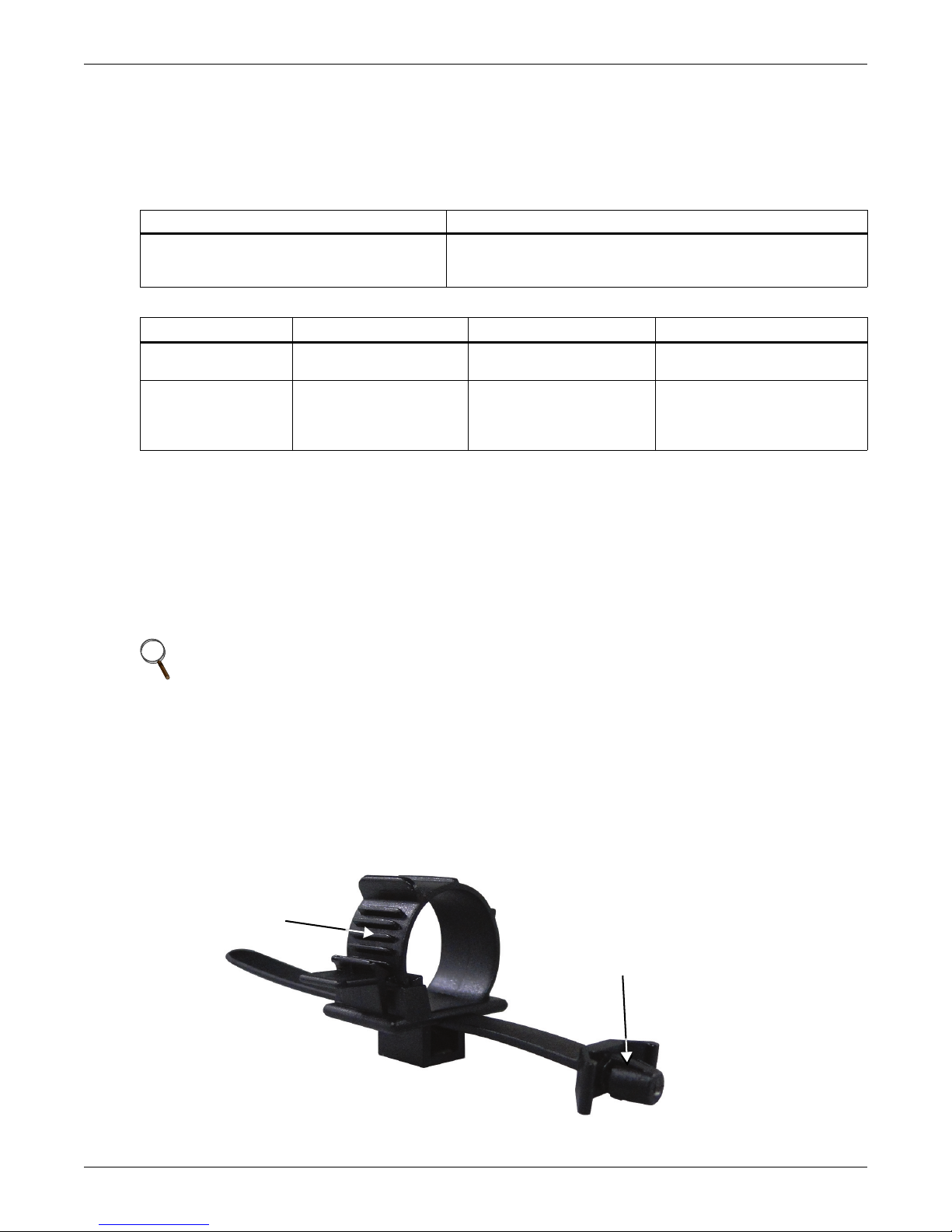
3. Install the two cable strain relief fixtures to secure either the input or output cables to prevent
accidental disconnection.
a. Insert one end into the provided holes on the rear of the unit.
b. Place the power cord(s) inside the loop.
c. Tighten the loop around the cables.
Figure 10 Cable strain relief
13 Liebert® GXT4
™
Page 20
2.5.2 Connecting Battery Cables
Liebert
GXT4
External
Battery
Cabinet
Battery Cable
1. Verify that the battery isolation breaker is in the Off (open) position.
2. Take out the battery cable included with the battery cabinet.
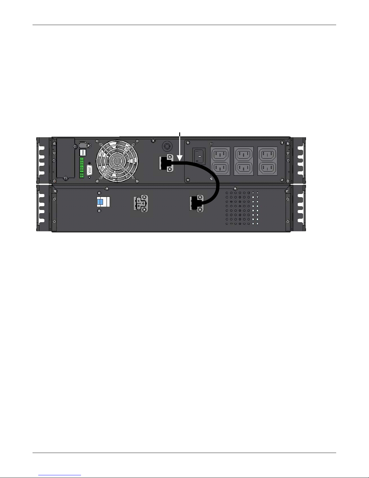
3. Connect one end of the battery cable to the external battery connector on the rear panel of the
UPS, and connect the other end to any battery port on the rear panel of the battery cabinet.
4. Repeat Steps 1 through 3 for each battery cabinet that will be connected to the system.
Additional battery cabinets will plug into the previously installed battery cabinet.
5. Switch On the battery breaker on the rear of the external battery cabinet.
6. Use the configuration program included with the UPS to specify the number of external battery
cabinets connected to the Liebert GXT4. See Table 17 for approximate battery run times.
Figure 11 Battery cable attachment
Installation
2.6 Connecting Communication Cables
Communication cable connection includes USB and optional card cables.
2.6.1 Connecting USB Communication Cables
1. Remove the USB communication cables from the accessories bag.
2. Insert one end of the USB communication cable to the USB port on the rear panel of the Liebert
GXT4 (see Figure 2).
3. Insert the other end of the USB communication cable to the USB port of the computer.
2.6.2 Installing the Optional Liebert IntelliSlot® Card and Communication Cables
1. Remove the protective cover from the Liebert IntelliSlot port on the Liebert GXT4 and set it aside.
2. Insert the Liebert IntelliSlot card into the Liebert IntelliSlot port and secure it with screws.
3. To connect any cable associated with a Liebert IntelliSlot card, refer to the user manual provided
with the card.
To configure and use the Liebert IntelliSlot communication card, refer to the card’s user manual.
Manuals for the various Liebert IntelliSlot cards are available at Liebert’s Web site:
www.liebert.com
Liebert® GXT4
™
14
Page 21
3.0 OPERATION AND DISPLAY PANEL
Liebert®GXT4
™
AC Power System
Battery Indicator
Bypass
Indicator
Inverter Indicator
Fault
Indicator
ESC
Programmable
Outlet1 Indicator
Programmable
Outlet2 Indicator
ECO Mode
Indicator
Down ButtonUp Button
ESC
Button
Enter
Button
1
2
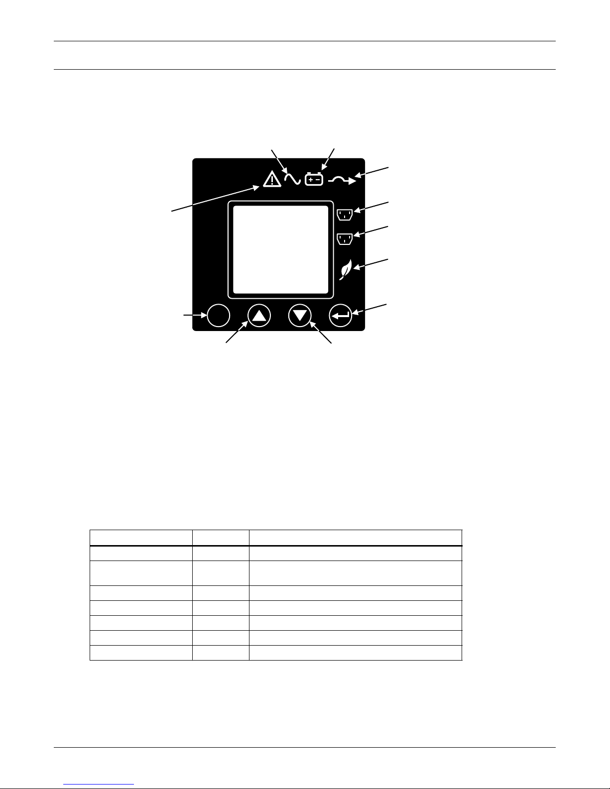
This chapter describes the Liebert GXT4 controls, particularly the operation and display panel on the
front of the Liebert GXT4. The panel has four control buttons, seven LED indicators and a liquid
crystal display (LCD), as shown in Figure 12.
Figure 12 Operation and display panel
Operation and Display Panel
3.1 LED Indicators
The seven LED indicators on the front of the operation and display panel are:
• Inverter
•Battery
•Bypass
• Programmable Outlet1
• Programmable Outlet2
• ECO Mode
•Fault
Figure 12 shows the indicators’ locations; their descriptions and functions are shown in Table 3.
Table 3 LED indicators
LED Indicators
Inverter Green On when the inverter is supplying power
Bypass Amber
Battery Amber On when the load is supplied by the battery
Fault Red On when an error has occurred within the UPS
Programmable Outlet1 Green On when programmable Outlet1 is On
Programmable Outlet2 Green On when programmable Outlet2 is On
ECO Mode Green On when the UPS is in ECO Mode
LED Color
Description
On when the load is supplied by the mains through
automatic/manual bypass
15 Liebert® GXT4
™
Page 22
3.2 Control Buttons
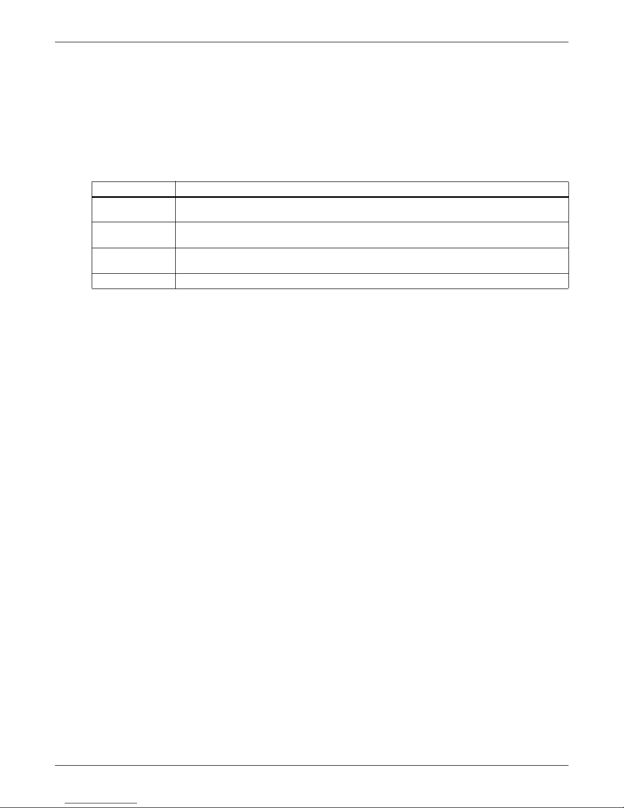
The four control buttons on the front of the operation and display panel are:
•ESC
•Up
•Down
•Enter
Figure 12 shows the buttons’ locations; their descriptions and functions are shown in Table 4.
Table 4 Control buttons
Control Buttons Description
ESC Button
Up Button
Down Button
Enter Button Pressing this button can enter the next level menu or confirm the parameter setting value.
3.3 LCD
The LCD panel shows the UPS status and enables changes to the UPS settings by assisting in
navigating through the Liebert GXT4’s menu (see 3.4 - Menu Structure).
Operation and Display Panel
Pressing this button returns to the previous menu or aborts any change in the input data field
before confirming.
Pressing this button can move the cursor up or increase the value displayed in the input data
field. When a menu is displayed on several screens, pressing the button can scroll up.
Pressing this button can move the cursor down or decrease the value displayed in the input
data field. When a menu is displayed on several screens, pressing the button can scroll down.
Liebert® GXT4
™
16
Page 23
3.4 Menu Structure
Audible Alarm
Control
Status
Configuration
Log
About
Alarm
Control
Batt Test
1. Audible Alarm On
2. Audible Alarm Off
1. Start
2. Cancel
3. Batt Test Result
PN/SN/Firmware Version
Turn UPS On
Turn UPS Off
Address: MAC
Address: IPV4
Address: IPV6STATIC
Address: IPV6AUTO
Address: IPV6LINK
Startup on Bypas s
Enable Auto Restart
Enable Auto Shutdown
Frequency Selection
Output Lev el Selec tion
Battery Cabinets
Low Battery Time Warning
Batt Test Interval
Batt Replace Time
BATT
UPS
Turn UPS
On/Off
View Log
Clear Log
Start
Windows
System
Status
Main
Menu
Network
Time Since Startup
Battery
Input
Load
Output
Sett ings as Outlet 1 (only Outlet 2)
Turn On Delay
Turn Off When UPS On Battery
and On Overload
Turn Off When UPS On Battery
for Some Time
Turn On W hen P ower Returns for
Some Time
Turn Off When R untime Les s
Than Some Time
Turn Off W hen Bat t C apacity
Less Than Some Time
LCD
Language
Color
Factory
Default
Control
Turn On
Turn Off
Reboot
Outlet 2
Outlet 1
Setting
ECO Mode
Frequency
Tolerance
Requalification
Time
Enable /Disable
Voltage
Tolerance
1 English
2 French
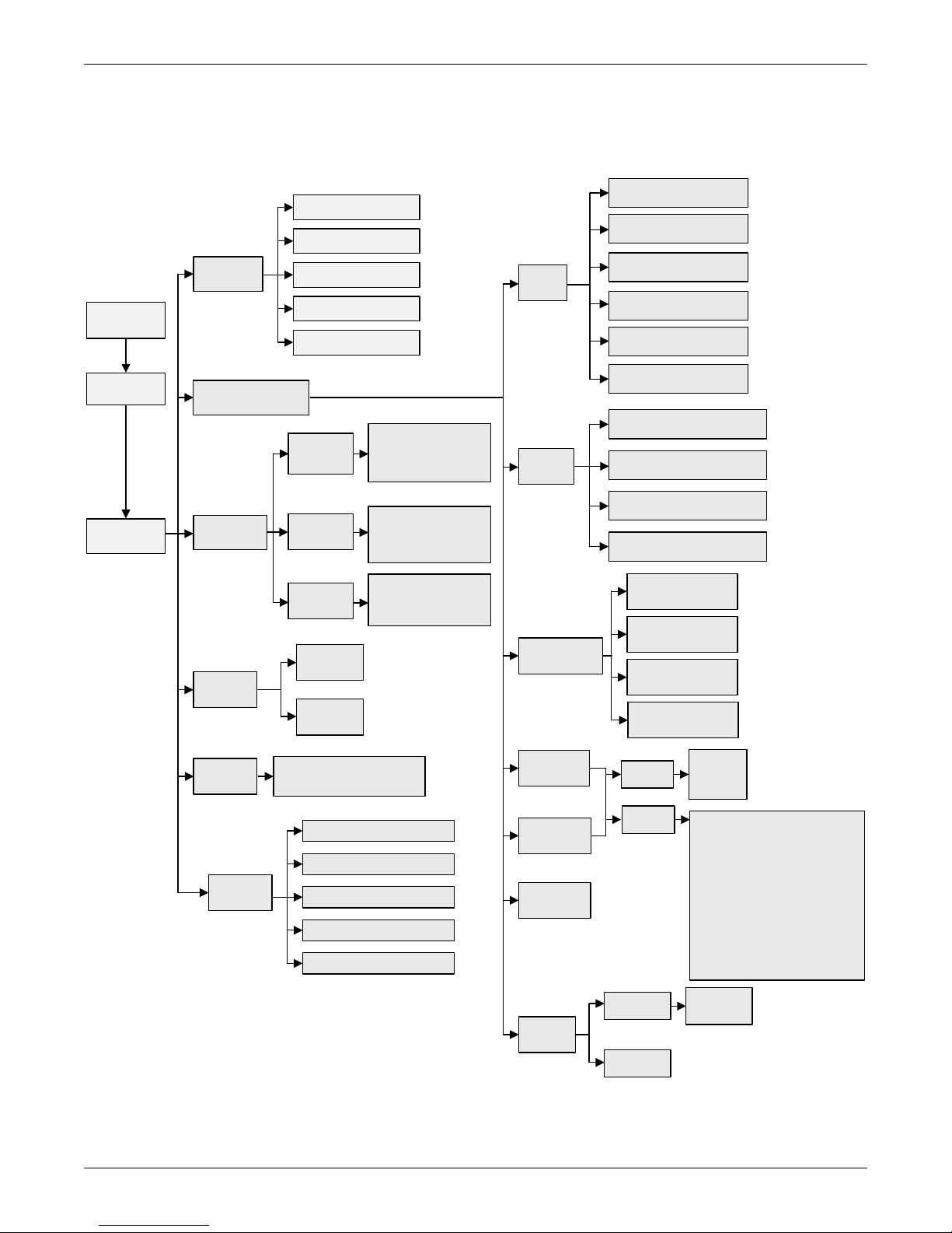
The menu structure of the LCD is shown in Figure 13.
Figure 13 Menu structure
Operation and Display Panel
17 Liebert® GXT4
™
Page 24
3.4.1 Startup Screen
EMERSON
Network Power
O/P: 0V HZ 0.0A
I/P : 230 V 50HZ 0.0A
BATT: 100% 320MINS
LOAD: 0%
TURN ON UPS
YES NO
O/P: 0V 0HZ 0.0A
I/P : 230V 50HZ 0.0A
BATT: 100% 320MINS
LOAD: 0%
AC NOT AVAILABLE
START ON BATTERY?
YES NO
Input Power is Available
Input Power is Not Available
O/P: 0V 0HZ 0.0A
I/P : 230V 50HZ 0.0A
BATT: 100% 320MINS
LOAD: 0%
UPS STARTING
O/P: 230V 50HZ 4.6A
I/P : 230V 50HZ 5.0A
BATT: 100% 15MINS
LOAD: 40%
START SUCCESSFUL
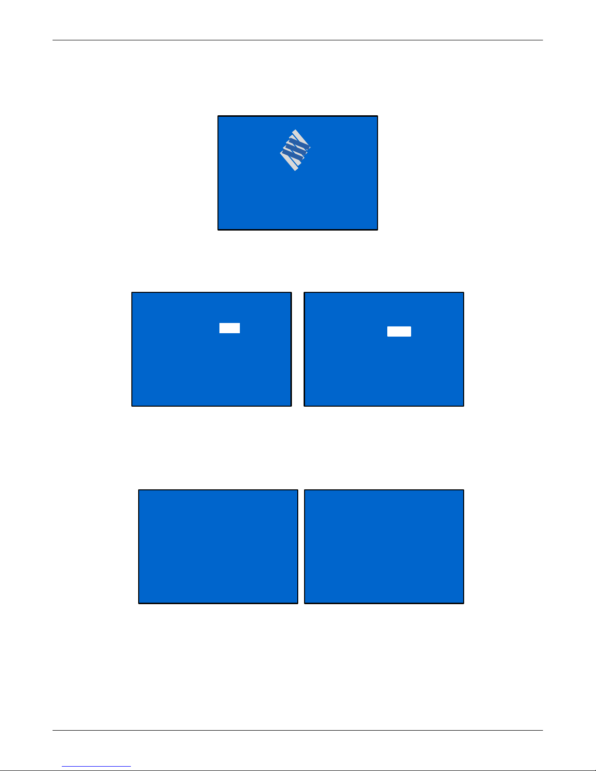
When the Liebert GXT4 is starting up, it initiates a self-test and displays the screen shown in
Figure 14 for about 10 seconds.
Figure 14 Startup screen
After about 10 seconds, the LCD shows one of the On screens in Figure 15; the screen shown depends
on whether input power is available.
Figure 15 Startup screens
Operation and Display Panel
To turn on the UPS, press either the Up or Down button to select YES and press the Enter button.
The UPS will start up, the LCD will display UPS STARTING and then START SUCCESSFUL after
the UPS is turned On, as shown in Figure 16.
Figure 16 Starting and Start Successful screens
Liebert® GXT4
™
18
Page 25

3.4.2 Default Screen
O/P: 230V 50HZ 11.7 A
I /P: 230V 50HZ 13.1A
BATT: 100% 3MINS
LOAD: 100%
GXT4-UPS 3KVA
Values shown will vary
according to installation
and configuration.
1 STATUS
2 CONFIGURATION
3 CONTROL
4LOG
5 ABOUT
6NETWORK
Press any button in the START SUCCESSFUL screen to enter the default interface, shown in
Figure 17.
Figure 17 Default screen
In the default screen, the LCD shows the UPS model, output parameters, input parameters, battery
capacity with run time estimate and load percentage. The UPS operation mode (online /inverter,
ECO, Battery or Bypass) will be indicated by the LED indicators.
If no control button (ESC, Up, Down, Enter) is pressed for 2 minutes, the LCD will enter the screen
saver mode (backlight turns off). It will remain off until a control button is pressed.
Operation and Display Panel
3.4.3 Main Menu Screen
Press the Enter button in the default screen to enter the MAIN MENU screen, as shown in
Figure 18.
Figure 18 Main Menu screen
To select a submenu, press the Up or Down button to move the cursor to the required item, then press
the Enter button to enter its submenu or set its parameter.
STATUS Screen
In the MAIN MENU screen, select STATUS to enter the Status Screen, displaying OUTPUT, LOAD,
INPUT, BATTERY and TIME SINCE STARTUP, as shown in Figure 19.
19 Liebert® GXT4
™
Page 26
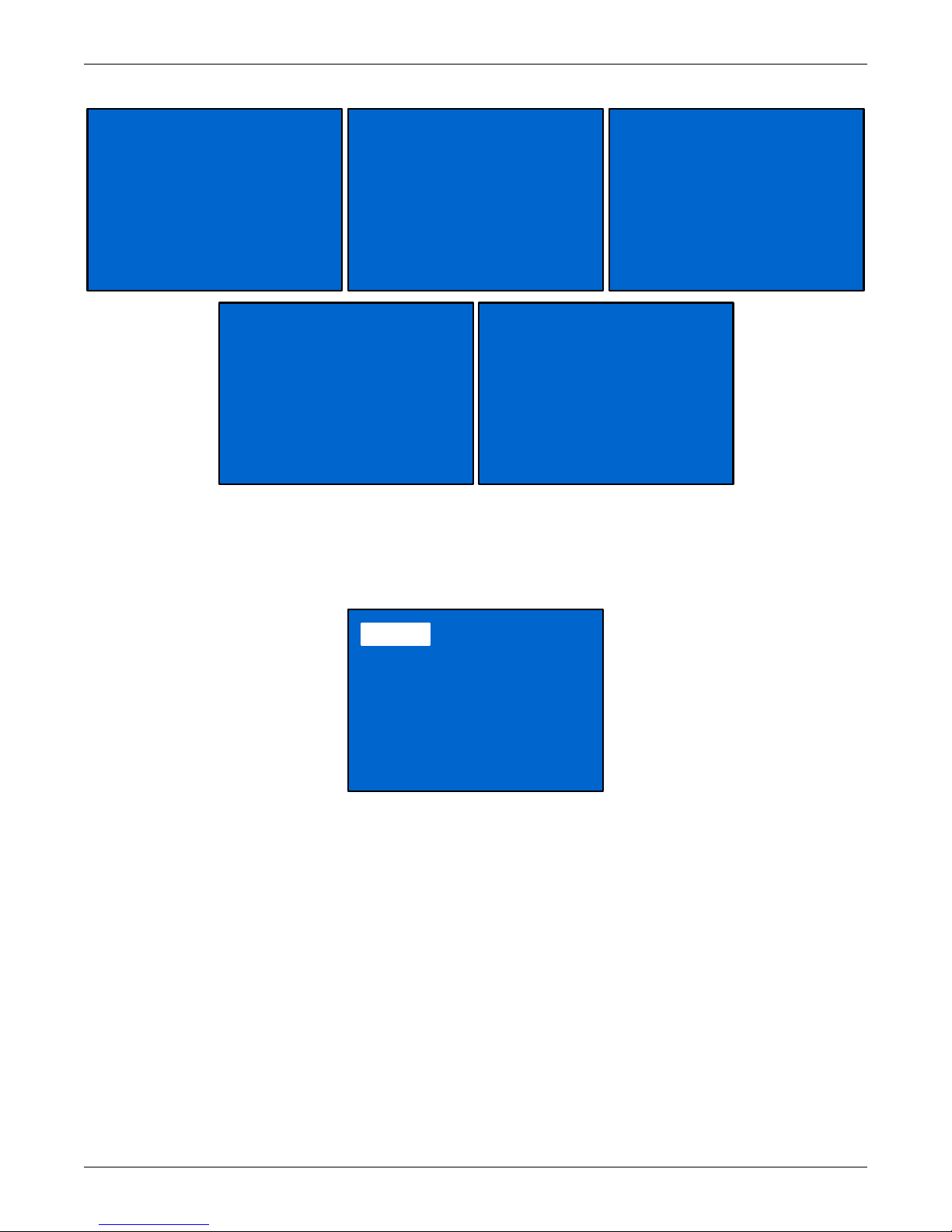
Figure 19 Status screens
VOLTAGE : 120V
FREQUENCY : 60HZ
CURRENT : 17.6A
POW ER : 2112 KWH
OUTPUT
CAP : 90%
WATT : 1620W
VA : 1800VA
LOAD
VOLT : 120V
FREQ : 60 HZ
CURR : 18.6A
POWER : 97KWH
INPUT
CAPACITY : 90%
RUNTIME : 100MINS
VOLTAGE : 80V
BATTERY
05D 15H 30M
TIME SINCE STARTUP
1. UPS
2. BATTERY
3. ECO MODE
4. OUTLET 1
5. OUTLET2
6. LCD
7. FACTORY DEFAULT
Operation and Display Panel
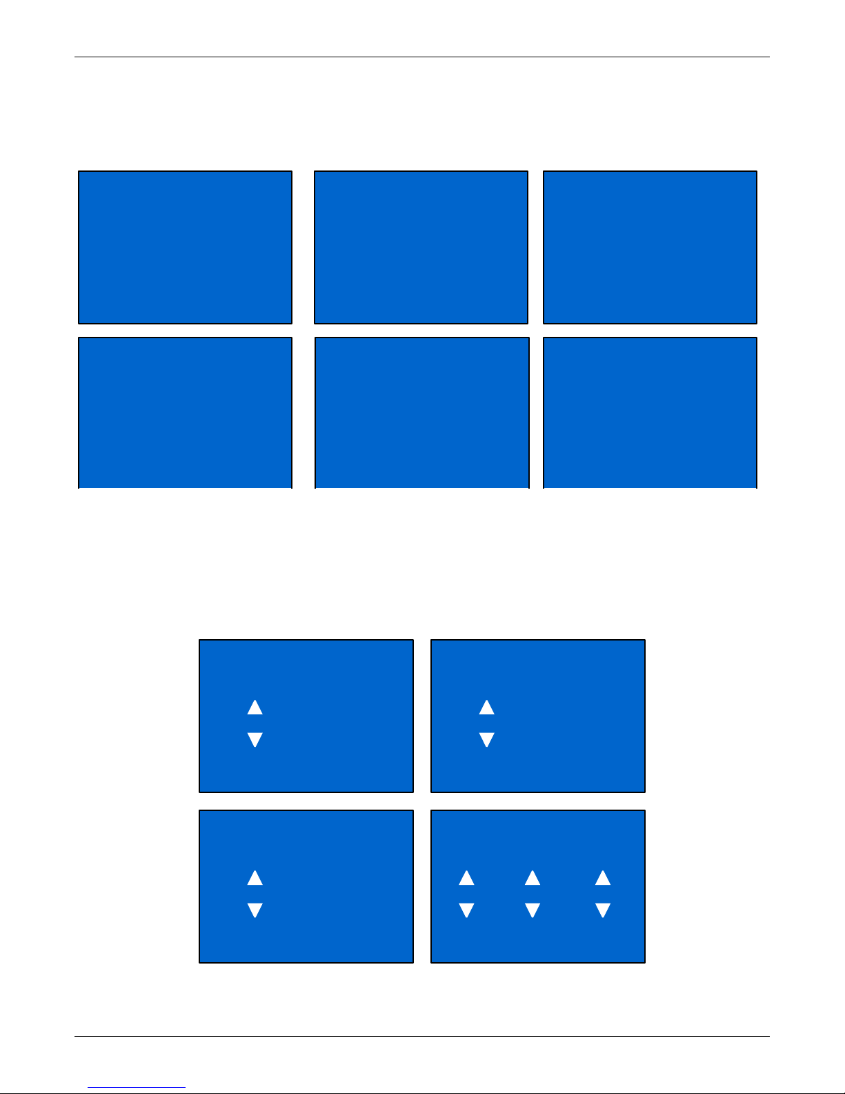
CONFIGURATION Screen
Select MAIN MENU > CONFIGURATION to enter the Configuration menu. This menu has seven
submenus, as shown in Figure 20.
Figure 20 CONFIGURATION screen
In the CONFIGURATION screen, press the Up or Down button to move the cursor to the required
item, then press the Enter button to enter a submenu or set its parameters.
Liebert® GXT4
™
20
Page 27
UPS Screen
OFF
AUDIBLE ALARM
NO
STARTUP ON BYPASS
NO
GUARANTEE SHUTDOWN
YES
ENABLE AUTO RESTART
AUTO - BYPASS ENABLE
FREQUENCY SELECTION
230
VOLTAGE SELECTION
0 CABINETS
EXT BATT CABINET
2MINS
LOW BATTERY TIME
8WEEKS
BATT TEST INTERVAL
2014 Y 1 M 1 D
BATT REPLACE TIME
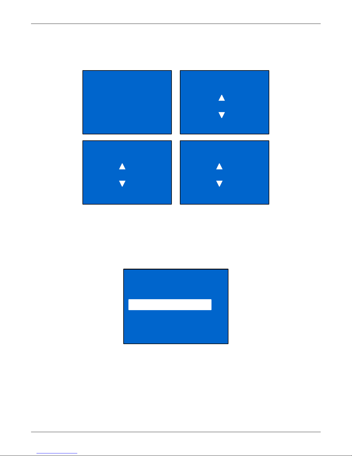
Select MAIN MENU > CONFIGURATION > UPS to enter the UPS screen. This menu has six
screens, as shown in Figure 21.
Figure 21 UPS screens
Operation and Display Panel
Press the Up or Down button to move the cursor to the required item, and press the Enter button to
confirm the settings.
Battery Screen
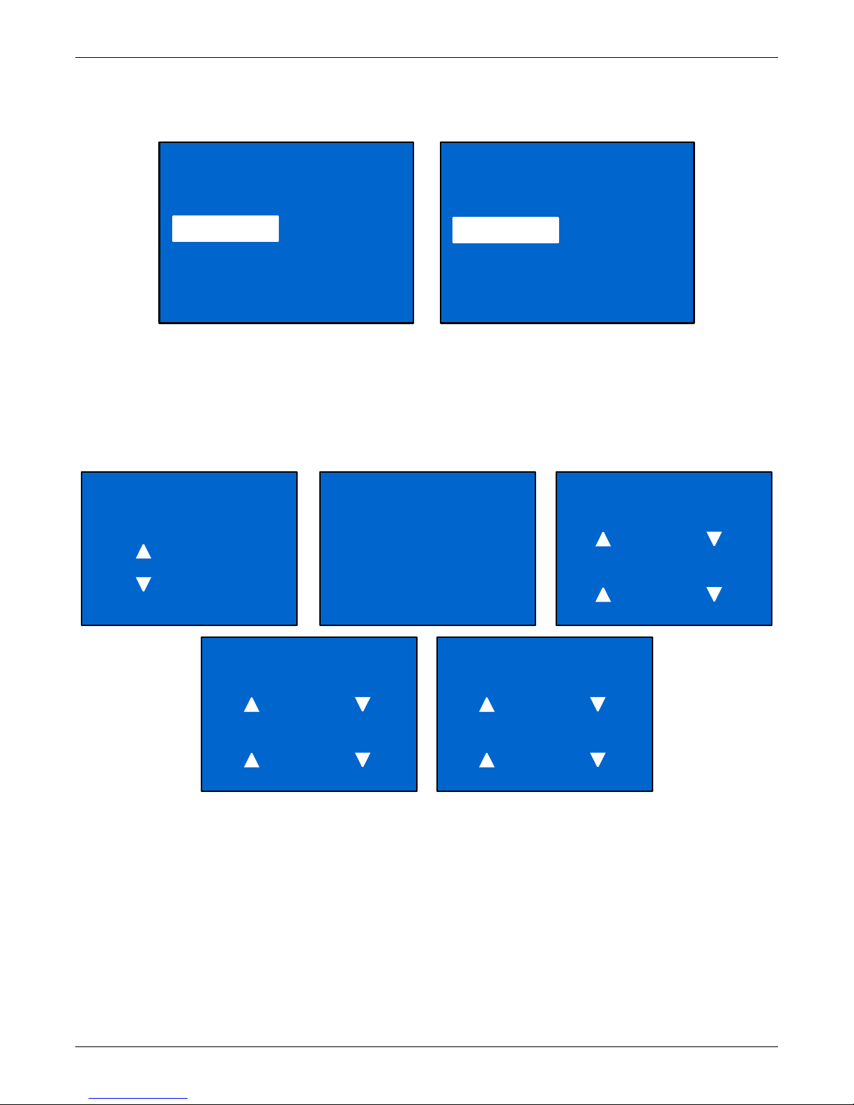
Select MAIN MENU > CONFIGURATION > BATTERY to enter the BATTERY screen. This menu
has four screens, as shown in Figure 22.
Figure 22 Battery screen
Press the Up or Down button to increase or decrease the value of the settings, and press the Enter
button to confirm it.
21 Liebert® GXT4
™
Page 28
ECO Mode Screens
ON
ECO MODE
3 Hz
FREQUENCY TOLERANCE
10%
VOLTAGE TOLERANCE
5 MINS
REQUALIFICATION TIME
OUTLET1
1 OUTLET CONTROL
2 OUTLET SETTING
Select MAIN MENU > CONFIGURATION > ECO MODE to enter the ECO MODE screens, as shown
in Figure 23.
Figure 23 ECO Mode screen
Operation and Display Panel
Press the Up or Down button to move the cursor to the required item, and press the Enter button to
confirm the settings.
Outlet1 Screen
Select MAIN MENU > 2 CONFIGURATION > 4 OUTLET1 to enter the OUTLET1 screen. This menu
has two submenus, as shown in Figure 24.
Figure 24 Outlet1 screen
Liebert® GXT4
™
22
Page 29
Select 1 OUTLET CONTROL and press the Enter button to enter the OUTLET CONTROL screen, as
OUTLET CONTROL
TURN OFF
REBOOT
Outlet Control is On Outlet Control is Off
OUTLET CONTROL
TURN ON
TURN OFF WHEN UPS
ON OVERLOAD AND ON
BATTERY
NO
TURN OFF WHEN UPS ON
BATTERY FOR
OFF
TURN ON WHEN POWER
RETURNS:
0 MINS
TURN OFF WHEN
RUNTIME LESS THAN
OFF
TURN ON WHEN POWER
RETURNS:
0 MINS
TURN OFF WHEN BATT
CAPACITY LESS THAN
OFF
TURN ON WHEN POWER
RETURNS:
0 MINS
TURN ON DELAY
0 MINS
shown in Figure 25.
Figure 25 Outlet Control screen
Press the Up or Down button to move the cursor to the required item, and press the Enter button to
confirm the settings.
Select 2 Outlet Setting and press the Enter button to enter the OUTLET SETTING screen, as shown
in Figure 26.
Figure 26 Outlet Setting screen
Operation and Display Panel
Press the Up or Down button to move the cursor to the required item, and press the Enter button to
confirm the settings.
23 Liebert® GXT4
™
Page 30

Outlet2 Screen
APPLY THE SAME
SETTINGS AS OUTLET1
YES NO
1 LANGUAGE
2 COLOR
1 English
2
The Outlet2 screens are the same as the Outlet1 screens. The same settings are available as on the
Outlet1 screen. If the Outlet2 group will have the same settings as the Outlet1 group, the Liebert
GXT4 offers a programming shortcut, as shown in Figure 27. When configuring the Outlet2 group,
the select YES and press the Enter button to apply the Outlet1 settings to the Outlet2 screen.
Figure 27 Outlet2 setting screen
LCD screen
Select Main Menu -> 2 CONFIGURATION -> 6 LCD to enter the LCD screen. This menu has two
submenus, as shown in Figure 28.
Operation and Display Panel
Figure 28 LCD screen
Select 1 LANGUAGE and press the Enter button to enter the LANGUAGE screen, as shown in
Figure 29.
The Liebert GXT4 is capable of supporting multiple languages. For the list of supported languages
and instructions on how to upload them, refer to the Configuration Program user manual on the
included CD.
Figure 29 Language screen
Liebert® GXT4
™
24
Page 31

Select 2 COLOR and press the Enter button to enter the COLOR screen, as shown in Figure 30.
EMERSON
EMERSON
EMERSON
EMERSON
RESET ALL SETTINGS
TO FACTORY DEFAULT
SETTINGS?
YES NO
1 TURN ON & OFF
2 ALARM CONTROL
3 BATT TEST
Figure 30 Color screen
FACTORY DEFAULT screen
Select MAIN MENU -> 2 CONFIGURATION -> 7 FACTORY DEFAULT to enter the FACTORY
DEFAULT screen, as shown in Figure 31.
Figure 31 Factory Default screen
Operation and Display Panel
Control Screen
Select MAIN MENU -> 3 CONTROL to enter the CONTROL screen. This screen has three submenus,
as shown in Figure 32.
Figure 32 Control screen
In the CONTROL screen, press the Up or Down button to move the cursor to the required item, and
press the Enter button to enter its submenu.
25 Liebert® GXT4
™
Page 32

TURN ON & OFF screen
TURN ON UPS
UPS is Off UPS is On
TURN OFF UPS
TURN ON UPS BYPASS
1 AUDIBLE ALARM ON
2 AUDIBLE ALARM OFF
1START
2 CANCEL
3 BATT TEST RESULT
Select MAIN MENU -> 3 CONTROL -> 1 TURN ON & OFF to enter the TURN ON & OFF screen.
This screen shows one of two displays, depending on the state of the UPS, as shown in Figure 33.
Figure 33 Turn UPS On or Off screen
ALARM CONTROL screen
Select MAIN MENU -> 3 CONTROL -> 2 ALARM CONTROL to enter the ALARM CONTROL screen,
as shown in Figure 34. This section allows active audible alarms to be silenced. To completely turn
off the audible alarm, refer to CONFIGURATION > UPS as shown in Figure 21.
Operation and Display Panel
Figure 34 Alarm Control screen
BATT TEST screen
Select MAIN MENU -> 3 CONTROL -> 3 BATT TEST to enter the BATT TEST screen, as shown in
Figure 35.
Figure 35 Batt Test screen
Liebert® GXT4
™
26
Page 33

Log Screen
1VIEW LOG
2 CLEAR LOG
255 OD 1H 17m AGO
UPS switch to Online
mode
254 /255
DO YOU WANT TO
CLEAR EVENT LOGS?
YES NO
PN: GXT4 -2000 RT230
SN:1XXX60XXX1AFCXX
FW VER: U100D100
HW VER: H100
Select MAIN MENU -> 4 LOG to enter the LOG screen. This screen has two submenus, as shown in
Figure 36.
Figure 36 Log screens
CLEAR LOG Screen
Select MAIN MENU > LOG > CLEAR LOG to enter the CLEAR LOG screen, as shown in Figure 37.
Figure 37 Clear Log screen
Operation and Display Panel
Press the Up or Down button to move the cursor to the required item. Press the Enter button to
confirm the settings.
ABOUT Screen
Select MAIN MENU> ABOUT to enter the ABOUT screen, as shown in Figure 38.
Figure 38 About screen
The ABOUT screen displays UPS model, serial number, software version and hardware version.
27 Liebert® GXT4
™
Page 34

Network
ADDRESS MAC
00-02-11-4X-AX
ADDRESSIPV4
10.163.226 .231 /24
ADDRESSIPV6 AUTO
::
ADDRESSIPV6 STATIC
::
ADDRESSIPV6 LINK
Fe80::202 :99ff:fe0f:4 ba
2%1
Select MAIN MENU>NETWORK to enter the NETWORK screen.
The NETWORK screen displays the MAC address and the IPv4 IP address. If the Liebert GXT4 is
fitted with an optional Liebert IntelliSlot Web card (Liebert IS-WEBCARD), the screen will display
IPv6 IP address settings (IPv6 requires configuration), as shown in Figure 39.
Figure 39 Network screens
Operation and Display Panel
Liebert® GXT4
™
28
Page 35
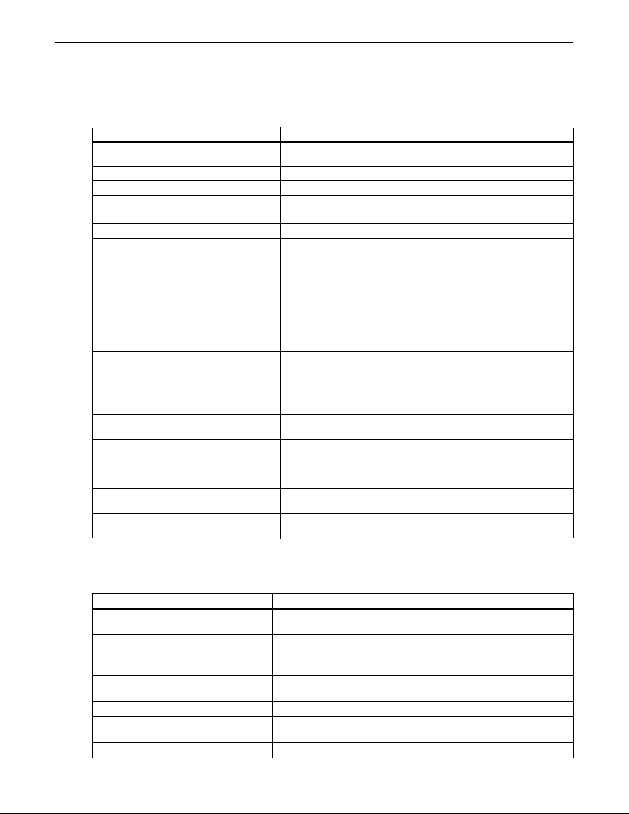
3.4.4 Prompt List
A prompt screen is displayed during the operation of the system to alert you to certain conditions
and/or to require your confirmation of a command or other operation. See Table 5 for the system
prompts and meanings.
Table 5 Prompts and meanings
Prompt Meanings
Mains Power Restored
UPS Return From A Low Battery Condition The UPS transfers back to mains (AC) mode from battery low mode.
UPS Return From Battery Mode The UPS transfers back to mains (AC) mode from battery mode.
UPS Self Test Successful The UPS self-test is successfully performed.
UPS Shutdown Command Received The UPS shut down was initiated through communication.
UPS Turn Off The UPS shuts down and has no output power.
UPS Turn On
UPS Shutdown Process Had Been
Cancelled
ECO Mode Enabled The UPS is configured to ECO mode operation,
ECO Mode Disabled
UPS Internal Temperature Return To
Normal
UPS Load Return From Overload
Load On Inverter The inverter is on and supplies protected power to the load.
Load On ECO Bypass
OUTLET1 Closed Auto / Manual
OUTLET1 Open Auto / Manual
OUTLET2 Closed Auto / Manual
OUTLET2 Open Auto / Manual
Bypass Power Restored
Operation and Display Panel
The mains power returns and the UPS transfers back to mains (AC)
mode.
The UPS starts up successfully and supplies protected power to the
load.
The shutdown command sent through Liebert MultiLink or SNMP
card to the UPS is canceled,
The UPS is configured to Online mode, supplying protected power to
the load through the inverter.
The internal temperature of the UPS recovers to normal range.
The loads are reduced, and the UPS recovers to normal state from
overload.
The UPS is on ECO mode; the mains is supplying power to the load
directly to reduce energy usage.
The programmable output receptacle 1 received a turn-off command
and is turned Off.
The programmable output receptacle 1 received a Turn-On
command and is turned On
The programmable output receptacle 2 received a Turn-Off
command and is turned Off.
The programmable output receptacle 2 received a turn-on command
and is turned On.
The bypass power recovered and the UPS can now transfer to
bypass.
3.4.5 Warning List
All UPS warning messages are described in Table 6.
Table 6 Warning list
Warning Description
Mains Power Not Available
UPS Batteries Low And Exhausted Soon The battery capacity is low and will be exhausted soon
UPS Has Switched To Battery Mode
Load On Bypass
Input Power Wiring Error L-N line reverse or PE not connected.
Bypass Power Not Available
UPS Maintenance Bypass Output The UPS transfers to maintenance bypass.
The mains power is not available, or it cannot satisfy the input
requirements for the UPS to operate from mains power
The mains power is abnormal or the PFC side is faulty, the UPS
transfers back to Battery mode
The UPS transfers to Bypass mode, at this point, the input mains
power supplies power to the load directly, and the load is not protected
The bypass power is not available, or it cannot satisfy the requirements
for the UPS transfers to bypass
29 Liebert® GXT4
™
Page 36
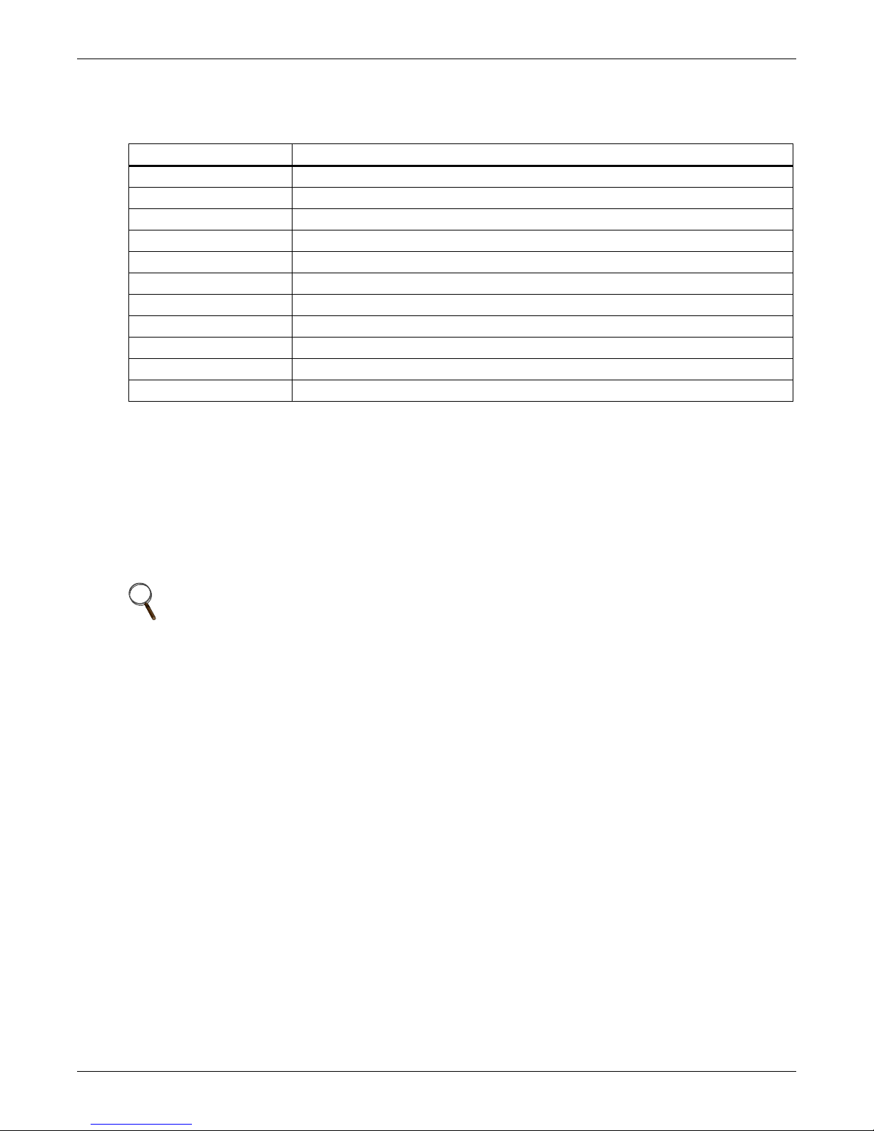
3.4.6 Fault List
All UPS fault messages are described in Table 7.
Table 7 Fault list
Fault Description
UPS Self-Test Failed The battery is bad or weak or not connected.
UPS Overload The UPS is overloaded.
Inverter Out Of Order The inverter has failed.
Battery Weak/Bad The battery is bad or weak.
Output Short Circuit The output connection is short-circuited.
DC Bus Overvoltage The DC bus is faulty.
UPS Overtemperature Overtemperature occurs to the UPS and the UPS will transfer to Bypass mode.
Charger Out Of Order The charger has failed.
Fan Out Of Order At least one fan is failed.
DC Bus Discharge Fail DC-DC failure occurs.
Rectifier Out Of Order Rectifier failure occurs.
If a fault occurs, the UPS automatically switches to Bypass Mode. The original operating mode will be
maintained only in the case of a battery disconnection fault. The fault message alternates with UPS
Mode once a second, the red fault indicator on the operation and display panel lights up and the alarm
sounds continuously.
Operation and Display Panel
If a fault occurs, proceed as follows:
1. Enter the ALARM CONTROL screen (see Figure 34), and select AUDIBLE ALARM ON or
AUDIBLE ALARM OFF to switch the alarm On or Off.
2. Enter the EVENT LOG screen (see Figure 36), and select VIEW LOG to view the entire Event log.
NOTE
There will be a short delay before the EVENT LOG screen displays the historical fault log to
allow the log to load.
Liebert® GXT4
™
30
Page 37

4.0 OPERATION
This section describes checks to be made before starting the UPS, how to start the UPS, manual
battery test, manual bypass, shutting down the UPS and disconnecting mains power from the UPS.
NOTE
The Liebert GXT4’s battery has been fully charged before delivery, but some charge will be lost
during storage and shipping. To ensure that the battery has adequate reserve power to protect
the connected load, charge the battery for three hours before putting the UPS into service.
4.1 Startup Checklist for the Liebert GXT4
Before starting the UPS, perform these checks:
___ 1. Check that the input plugs and loads are connected properly and reliably.
___ 2. Check that the battery cable is connected properly.
___ 3. Check that the communication cables are connected properly.
4.2 Starting the UPS
1. Plug the UPS into the appropriate AC outlet.
2. 3000VA models only—Close the input breaker on the rear of the unit.
3. The UPS will begin the startup sequence once AC power is present.
Operation
NOTE
The UPS will sound an audible alarmist is normal
4. On the LCD, press either the Up or Down button once, then press the Enter button to turn on the
UPS. The UPS will sound the audible alarm again when the output receptacles are being supplied
by the internal bypass. It will sound one more time as the inverter powers the connected
equipment.
5. Check the LCD and LED indicators to ensure the UPS is operating normally.
6. Check the load percentage on the default screen to ensure the connected equipment is not
exceeding the UPS rated capacity.
The UPS is now providing conditioned power to the connected load.
4.3 Manual Battery Test
To initiate a manual battery test, select MAIN MENU > CONTROL>BATT TEST>START.
• If the battery test results show FAILED, allow the UPS to recharge the batteries for 24 hours.
• Retest the batteries after 24 hours of charging.
• After the batteries have been retested, if the battery test still shows FAILED, contact your local
Emerson
®
representative or Emerson Network Power Channel Support.
4.4 Manual Bypass
To manually transfer the connected equipment to the internal bypass:
1. From the main menu select CONTROL, then press Enter.
2. Select TURN ON & OFF and press Enter.
3. Select TURN UPS BYPASS and press Enter. The UPS will transfer the connected loads to the
internal bypass.
If the internal bypass is not available because of mains power problems, pressing this button once will
be ignored. Bypass operation is indicated by an audible alarm and illuminated amber Bypass
indicator. (If other indicators are illuminated, refer to 7.0 - Troubleshooting.)
31 Liebert® GXT4
™
Page 38

4.5 Shut Down the Liebert GXT4
To shut down the UPS from the LCD:
1. From the Main Menu select CONTROL, press Enter, then select TURN ON & OFF.
2. Press the enter key.
3. Select TURN UPS OFF, then press Enter.
4. Press either the Up or Down button to move the cursor to confirm the shutdown command and
press Enter. The UPS will sound an audible alarm; this is normal.
Power to the connected equipment is now Off.
5. The UPS display will still be illuminated because the batteries are still being charged.
The UPS display will still be illuminated because the batteries are still being charged. The UPS may
now be disconnected from AC power, and the UPS will completely shut down in approximately 15
seconds.
4.6 Disconnecting Input Power from the Liebert GXT4
1. After the UPS has been shut down as detailed in 4.5 - Shut Down the Liebert GXT4,
disconnect the input cable from the wall socket.
2. Wait 30 seconds and verify that all indicators have turned Off and the fan has stopped; this
indicates that the power-off is complete.
3. Turn the external battery cabinet breaker switch to the Off position if the UPS has an external
battery cabinet.
Operation
After powering Off the UPS, the UPS ceases output and the load is powered Off.
Liebert® GXT4
™
32
Page 39

5.0 COMMUNICATION
!
This section describes the four types of communication ports on the rear of the UPS:
• Liebert IntelliSlot
• USB port (standard B-type)
• Terminal Block Communication
•RS232 port (DB9F)
®
port
CAUTION
To maintain safety (SELV) barriers and for electromagnetic compatibility, signal cables
should be segregated and run separate from all other power cables.
5.1 Liebert IntelliSlot Communication Cards
The Liebert IntelliSlot port accepts four optional cards:
• Liebert IntelliSlot Web Card (IS-WEBCARD)
• Liebert IntelliSlot Relay Card (IS-RELAY)
• Liebert IntelliSlot MultiPort Card (IS-MULTIPORT)
• Liebert IntelliSlot Unity Card (IS-UNITY-DP)
The Liebert IntelliSlot Web Card provides SNMP monitoring and control of the UPS across the
network.
Communication
The Liebert IntelliSlot Relay Card provides dry contact relay outputs for custom-wired applications
and delivers support for Liebert MultiLink
The Liebert IntelliSlot MultiPort Card provides four sets of contacts for support of up to four
computers that have Liebert MultiLink installed.
The Liebert IntelliSlot Unity Card provides SNMP and/or RS-485 monitoring of the UPS across the
network and/or building management system. The Liebert IntelliSlot UNITY card also enables
monitoring external temperature, humidity and contact closure inputs using external sensors. (The
Liebert IS-UNITY-DP compatibility will be a future release, contact your Emerson sales
representative for availability.)
Follow instructions provided with the Liebert IntelliSlot card to configure Liebert MultiLink
UPS or any additional ancillary product for the Liebert GXT4. These instructions are available at:
multilink.liebert.com
5.1.1 Liebert MultiLink
Liebert MultiLink monitors the UPS continuously and can shut down the computer or server in the
event of an extended power failure. Liebert MultiLink can also be configured to shut down the UPS.
Liebert MultiLink can communicate with the UPS via the USB port, RS232 port, contact closures via
terminal block or over the network via SNMP using the Liebert IS-WEBCARD. An optional Liebert
MultiLink license kit permits shutting down multiple computers that are protected by the UPS.
For more information about the Liebert IntelliSlot SNMP Card, Liebert IntelliSlot Web Card and
Liebert MultiLink License Kits, visit the Liebert Web site (www.liebert.com) or contact your local
Emerson
®
representative.
®
shutdown software.
®
, the
33 Liebert® GXT4
™
Page 40
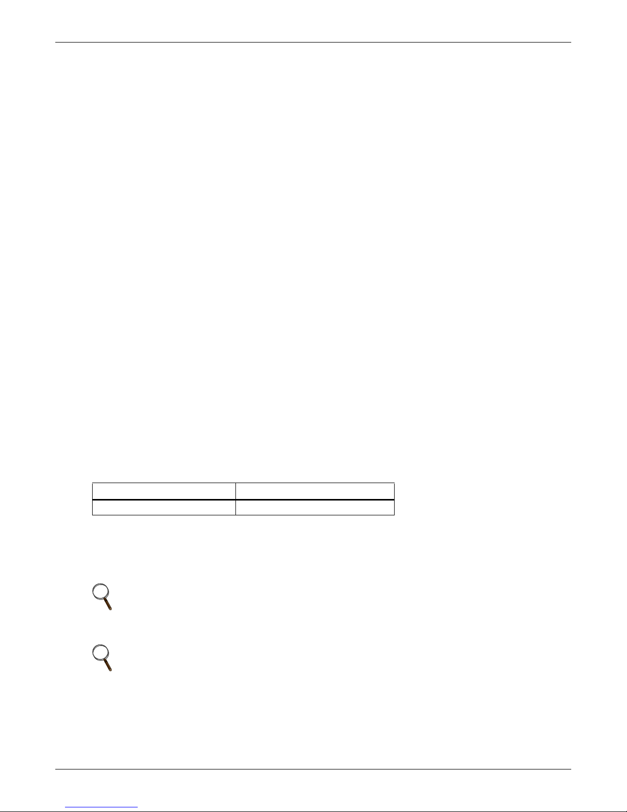
5.2 USB Port Communication
Communication
The standard B-type USB port is used to connect the UPS and network server or other computer
system using Liebert MultiLink
A standard B-type USB port is provided to allow connection to a computer or network server. The
USB port can be used to communicate with the Liebert GXT4 configuration program (see section 5.2.1
for details) or Liebert MultiLink (refer to 5.1.1 - Liebert MultiLink for description) that is provided
on the CD that is included with the UPS.
5.2.1 Configuration Program
The configuration program is on the Liebert GXT4 CD and can be used instead of making
configuration setting changes from the LCD panel. The configuration program communicates to a
computer running a Microsoft
For most users, the factory default settings are adequate. This section give a brief overview of the
features and parameters that are available for modification, as well as the factory default settings.
Should any changes be necessary, refer to the Configuration Program User Manual that is located on
the included CD for further details.
The configuration program allows these features of the Liebert GXT4 to be changed:
• Change and set the display language
• Enable/Disable Auto-Restart (default is Enable)
• Select frequency converter operation with a fixed output frequency of 50Hz or 60Hz, bypass
disabled (default is Auto-Select with bypass enabled)
• Set the Low Battery Warning alarm time from 2 to 30 minutes (default is 2 minutes)
• Enable/Disable the Auto-Battery test (default is Enable)
• Enable/Disable Auto-Restart after removing Remote shutdown (default is Disable)
• Set the wiring mode of Remote shutdown (default is normally open)
• Set the Auto-Enable output after remote shutdown (default is Disable)
• Set the Auto-Battery test to 8, 12, 16, 20, or 26 weeks (default is 8 weeks)
• Select the number of external battery cabinets connected to the UPS to adjust the remaining run
time calculated by Emerson
• Select one of multiple output voltages to match various voltages (see Table 8).
Table 8 Output voltage option, all models
Factory Default Setting Output Voltage Option
230VAC 200V, 208V, 220V, 230V, 240V
®
.
®
Windows® operating system via the included USB cable.
®
software products (default is zero)
NOTICE
The output voltage settings cannot be changed while the UPS is On and powering connected
loads.
NOTE
Programming the output voltage of a 230V model of the Liebert GXT4 to 220V automatically
derates the UPS to 96% of both the VA and watt ratings (refer to 9.0 - Specifications for VA
and watt ratings).
NOTE
• This program is compatible with UPS models beginning with ‘GXT4,’ as in
‘GXT4-3000RT230.’ It is not compatible with earlier versions of the Liebert GXT UPS.
• A computer running Microsoft
Windows 7 or Windows 8 is required to set up and run the configuration program.
Liebert® GXT4
™
®
Windows 2000®, Windows XP®, Windows Vista®,
34
Page 41
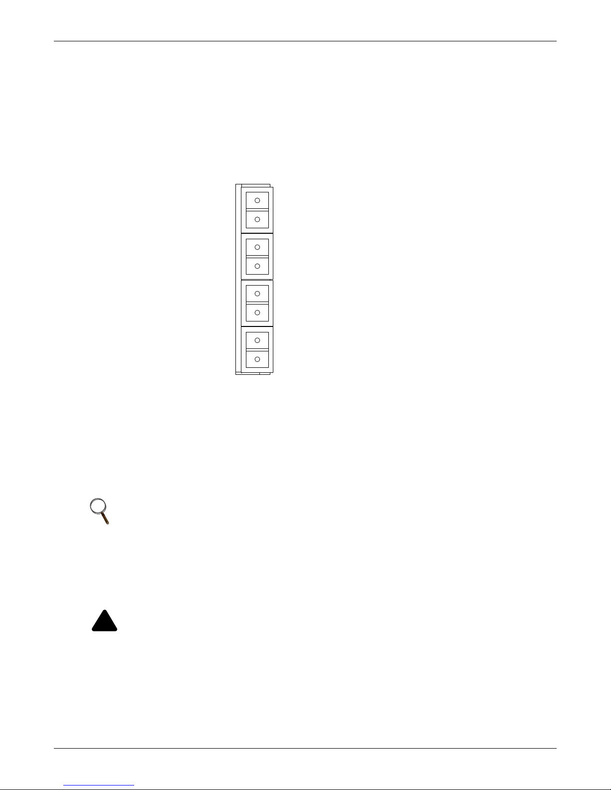
5.3 RS-232 Port
!
1
3
4
5
6
7
8
2
Low Battery
On Battery Mode
Battery Mode
Shutdown
Any Mode
Shutdown
The RS-232 port uses an Emerson® proprietary protocol that is for use with Liebert MultiLink®. This
port enables a more secure connection instead of the USB cable, to the computer or server that has
Liebert MultiLink installed.
5.4 Terminal Block Communication
The Terminal Block includes eight pins, as shown in Figure 40.
Figure 40 Terminal Block Communication pin layout
Communication
5.4.1 Any Mode Shutdown
The purpose of Any Mode Shutdown is to shut down the UPS output by turning Off the rectifier,
inverter and static switch so that there is no power to the loads.
Any Mode Shutdown can be operated locally or remotely:
• Local Any Mode Shutdown can be performed by shorting Pin 1 and Pin 2.
• Remote Any Mode Shutdown can be performed using a switch connected to Pin 1 and Pin 2 and
mounted at a remote location.
NOTE
Remote Power Off will be performed either by NO or NC contact of Any Mode Shutdown,
depending on the settings in the configuration program.
A current-limited source for this optocoupler (+12VDC, 50mA) will be available from the UPS.
The connection to the UPS for remote connection will be via terminal block connector.
Any Mode Shutdown wiring must conform to all national, regional and local wiring
regulations.
WARNING
When the Auto-Enable output option is selected and the UPS output is disabled using Pin 1
and Pin 2, the Liebert GXT4’s output can turn On automatically and without warning if the
Pin 1 and Pin 2 connection is changed.
35 Liebert® GXT4
™
Page 42

5.4.2 Battery Mode Shutdown
Battery Mode Shutdown permits shutting down the UPS by turning Off the rectifier, inverter and
static switch so that there is no power to the load when the UPS is On Battery. The auxiliary power
for the UPS will still be active.
Battery Mode Shutdown can be performed locally or remotely:
• Local Battery Mode shutdown can be performed by shorting Pin3 and Pin4.
• Remote Battery Mode Shutdown can be performed using a switch connected to Pin3 and Pin4 and
mounted at remote location.
NOTE
Remote Power Off will be performed by NO contact.
A current-limited source (+12VDC, 50mA) will be available from UPS.
The connection to the Liebert GXT4 for remote connection will be via terminal block connector.
Battery Mode Shutdown wiring must conform to all national, regional and local wiring codes
and laws.
This signal must last for 1.5 seconds or longer.
A battery shutdown signal will not cause an immediate shutdown. It will start a 2-minute
shutdown timer. This timer cannot be stopped once triggered. If the mains power returns
during this countdown, the Liebert GXT4 will still shut down and must remain shut down for
10 seconds. Whether the UPS turns back On when the power is restored depends on the
auto-restart setting.
Communication
5.4.3 On Battery
On Battery signal is a Normally Open (NO) dry contact. When the UPS is supplying output power
from the battery this dry contact will be closed.
5.4.4 Low Battery
Low Battery signal is a Normally Open (NO) dry contact. When the UPS is supplying output power
from the battery and has reached the Low Battery Warning time selected in the configuration
program, this dry contact will be closed.
NOTE
The rated values for the dry contacts for the On Battery and Low Battery signals are:
• Rated Voltage: 30V (AC or DC)
• Rated Current: 300mA
Liebert® GXT4
™
36
Page 43
6.0 MAINTENANCE
!
!
This section describes replacing the internal battery pack, precautions, checking the Liebert GXT4’s
status and checking UPS functions.
WARNING
The battery can present a risk of electrical shock and high short circuit current. The following
precautions should be observed before replacing the battery pack:
• Remove rings, watches and other metal objects.
• Use tools with insulated handles.
• Do not lay tools or other metal objects on the batteries.
• If the battery kit is damaged in any way or shows signs of leakage, contact your local
Emerson
• Do not dispose of batteries in a fire. The batteries may explode.
• Handle, transport and recycle batteries in accordance with local regulations.
6.1 Replacing the Internal Battery Pack
The Liebert GXT4 is designed to allow the user to replace the internal battery pack safely. Refer to
Table 9 for internal battery pack part numbers for Liebert GXT4 UPS:
Table 9 Replacement battery pack model numbers
UPS Rating, VA
700/1000 GXT4-5A48BATKIT 1
1500 GXT4-9A48BATKIT 1
2000 GXT4-9A48BATKIT 1
3000 GXT4-9A72BATKIT 1
®
representative immediately.
Replacement Internal Battery
Pack Model #
Maintenance
Quantity
Required
Read all safety cautions before proceeding. A trained user can replace the internal battery pack when
the UPS is always in a restricted access location (such as a rack or server closet). Contact your local
dealer or Emerson representative to obtain the pricing of the appropriate replacement battery pack.
CAUTION
Risk of explosion if battery is replaced by an incorrect type. Dispose of used batteries
according to the instructions.
37 Liebert® GXT4
™
Page 44
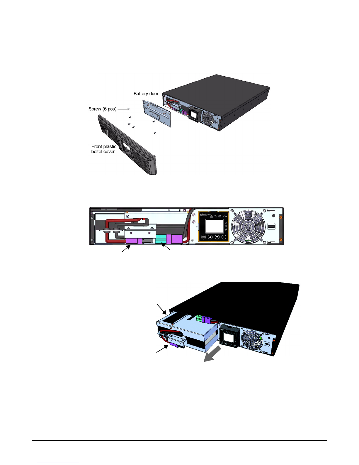
6.1.1 Battery Replacement Procedures
Battery Connector
Battery Receptacle
Internal Battery Pack
Battery Handle
Pull Out with Battery Handle
1. Gently remove the front plastic bezel cover from the UPS.
2. Loosen and remove the six screws on the battery door, as shown in Figure 41.
3. Lay the battery door and screws aside for reassembly.
Figure 41 Removing the front plastic bezel cover and battery door
4. Gently pull the battery wire out and disconnect the battery plug and battery receptacle, as shown
in Figure 42.
Figure 42 Disconnecting the battery plug and battery connector (front view)
Maintenance
5. Grasp the battery handle and pull the internal battery pack out of the UPS, as shown in
Figure 43.
Figure 43 Pulling out the battery
6. Unpack the new internal battery pack. Take care not to destroy the packing.
Compare the new and old internal battery packs to make sure they are the same type and model.
If they are the same, proceed with Step 7; if they are different, stop and contact your local
Emerson
®
representative or Emerson Channel Support.
7. Line up and slide in the new internal battery pack.
8. Reconnect the battery plug and battery receptacle
9. Gently push the battery wire and internal battery pack back into the UPS.
Liebert® GXT4
™
38
Page 45

10. Reattach the front battery door with the six screws.
11. Reattach the front plastic bezel cover to the UPS.
NOTE
The internal battery pack is hot-swappable. However, caution should be exercised because
during this procedure the load is unprotected from disturbances and power outages.
Do not replace the battery while the UPS is in Battery Mode. This will result in a loss of output
power and will drop the connected load.
6.2 Battery Charging
The batteries are valve-regulated, nonspillable, lead acid and should be kept charged to attain their
design life. The Liebert GXT4 charges the batteries continuously when it is connected to the mains
input power.
If the Liebert GXT4 will be stored for a long time, Emerson recommends connecting the UPS to input
power for at least 24 hours every three to four months to ensure full recharge of the batteries.
6.3 Precautions
Although the Liebert GXT4 has been designed and manufactured to ensure personal safety, improper
use can result in electrical shock or fire. To ensure safety, observe the following precautions:
• Turn Off and unplug the Liebert GXT4 before cleaning it.
• Clean the UPS with a dry cloth. Do not use liquid or aerosol cleaners.
• Never block or insert any objects into the ventilation holes or other openings of the UPS.
• Do not place the Liebert GXT4 power cord where it might be damaged.
Maintenance
6.4 Checking UPS Status
Emerson® recommends checking the UPS operation status every six months.
• Check whether the UPS is faulty: Is the Fault Indicator On? Is the UPS sounding an alarm?
• Check whether the UPS is operating in Bypass Mode. Normally, the UPS operates in Normal
Mode. If it is operating in Bypass Mode, stop and contact your local Emerson representative, or
Emerson Channel Support.
• Check whether the battery is discharging. When the mains input is normal, the battery should
not discharge. If the UPS is operating in Battery Mode, stop and contact your local Emerson
representative or Emerson Channel Support.
39 Liebert® GXT4
™
Page 46
7.0 TROUBLESHOOTING
This section indicates various UPS symptoms a user may encounter and provides a troubleshooting
guide in the event the UPS develops a problem. Use the following information to determine whether
external factors caused the problem and how to remedy the situation.
7.1 UPS Symptoms
The following symptoms indicate the Liebert GXT4 is malfunctioning:
• The relative indicators illuminate, indicating the UPS has detected a problem.
• An alarm buzzer sounds, alerting the user that the UPS requires attention.
7.1.1 Indicator and LCD
In addition to the fault indicator being illuminated, the LCD will display the fault. The displayed
fault on the LCD is described in Table 10
Table 10 Description of the displayed fault
Displayed Fault Cause Corrective Steps
UPS self test failed The battery is bad or weak. Contact customer service.
UPS shutdown
command received
UPS overload The UPS is overloaded.
Inverter Out of Order The inverter is faulty. Contact customer service.
Battery Weak/Bad The battery is bad or weak. Replace the battery.
Output Short Circuit The output connection is short-circuited.
DC Bus Overvoltage The DC bus is faulty. Contact customer service.
UPS Overtemperature
Charger Out of Order The charger is faulty. Contact customer service.
Fan Out of Order At least one fan is faulty. Contact customer service.
DC Bus Discharge Fail A DC-DC failure occurs. Contact customer service.
The UPS shuts down through
communication.
Over-temperature occurs to the UPS and the
UPS will transfer to Bypass mode.
Troubleshooting
Contact customer service.
Reduce the load and contact customer
service.
Shut down the equipment and contact
customer service.
Reduce the load and contact customer
service.
NOTE
If the UPS encounters a fault and no correction attempt is performed within 2 minutes, the
LCD backlight will flash (on 1 second and off 1 second) as an alert.
Press any button to exit the alert mode. If no correction attempt is performed on the UPS, the
LCD backlight will flash again until the UPS fault is corrected.
Liebert® GXT4
™
40
Page 47
7.1.2 Audible Alarm
An audible alarm will sound in conjunction with the visual indicators to indicate a change in UPS
operating status. The audible alarm will sound as described in Table 11.
Table 11 Audible alarm description
Condition Alarm
Battery discharge Half-second beep every 10 seconds
Low battery Two half-second beeps every 5 seconds
UPS fault, load on bypass 1-second beep every 4 seconds
UPS fault, no power to load Continuous
Overload Half-second beep every half second
Battery replacement 2-second beep every 2 minutes
Battery loss Continuous
Wiring problem (loss of proper grounding for UPS) Continuous
Bypass reminder 1-second beep every 60 seconds
7.2 Troubleshooting
Troubleshooting
In the event of an issue with the UPS, refer to Table 12 to determine the cause and solution. If the
fault persists, contact Emerson
®
Channel Support.
Table 12 Troubleshooting table
Problem Cause Solution
UPS fails to start
Battery indicator
is illuminated
UPS has
reduced battery
backup time
Battery indicator
is flashing.
Bypass indicator
is flashing.
UPS is short-circuited or
overloaded
Batteries are not charged
enough or not connected
UPS is not plugged in
UPS input protection fuse has
blown/opened
Mains power is out of tolerance
Batteries are not fully charged
UPS is overloaded Check load level indicator and reduce the load on the UPS.
Batteries may not be able to
hold a full charge due to age
Battery source is not available;
continuous horn.
Because the voltage or
frequency is outside acceptable
limits, the bypass is disabled.
Ensure UPS is Off. Disconnect all loads and ensure nothing is lodged in
output receptacles. Ensure loads are not defective or shorted internally.
Check to ensure the internal battery is connected. If it is not, make the
connection and try to start the unit. If the battery is connected, leave the
UPS connected to input power for 24 hours to recharge batteries, then try
to start the unit.
UPS is operating from battery mode. Ensure UPS is securely plugged
into the wall receptacle.
UPS is operating from battery mode. Save data and close applications.
Replace UPS input fuse, then restart UPS.
UPS is operating from battery mode. Save data and close applications.
Ensure mains supply voltage is within acceptable limits for UPS.
Keep UPS plugged in continuously at least 24 hours to recharge
batteries.
Replace batteries. Contact your local dealer, Emerson representative or
Emerson Channel Support for replacement battery kit.
Check battery connections, completely power down and restart UPS.
NOTE: If the battery circuit opens while the UPS is running, it will be
detected when the next battery test is performed.
The AC input powers the PFC input and serves as the bypass source. If
the AC is present but the voltage or frequency exceeds the acceptable
range for safe operation with a load, the bypass will be disabled and this
indicator will flash, indicating that the bypass is unavailable.
When reporting a UPS issue to Emerson, include the UPS model and serial number. These are
located in several places for your ease of location: on the top panel (rack mount orientation); the left
side (tower orientation); the rear panel; on the front of the unit behind the front plastic bezel; and on
the LCD select MAIN MENU > ABOUT.
41 Liebert® GXT4
™
Page 48
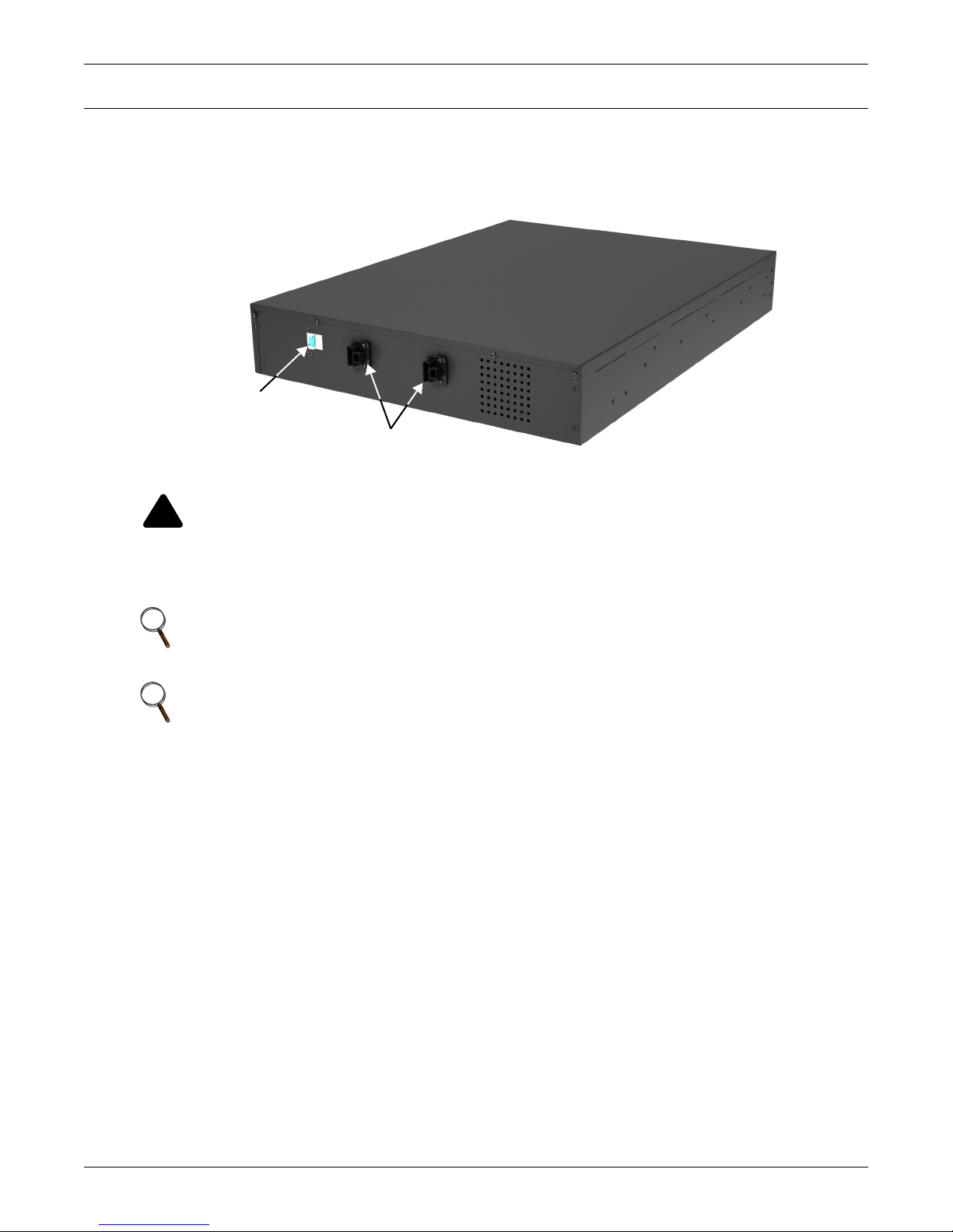
8.0 BATTERY CABINET
!
External Battery
Connector
Isolation Breaker
Optional battery cabinets are available for the Liebert GXT4. The external battery connector and
isolation breaker are on the battery cabinet’s rear panel, as shown in Figure 44. For battery cabinet
specifications, refer to Table 15.
Figure 44 Battery cabinet
Battery Cabinet
WARNING
Do not contact the external battery connector and ground without wearing protective gloves
and clothing and taking other precautions against electrical shock. The battery loop and AC
input are not insulated, which may cause a dangerous voltage between the external battery
connector and ground.
NOTE
External battery connectors are wired in parallel. Either connector can be connected to the UPS
or to another battery cabinet.
NOTE
The length of the standard battery cable delivered with the battery cabinet is 0.65m (2.13ft).
Liebert® GXT4
™
42
Page 49

9.0 SPECIFICATIONS
The specifications of the Liebert GXT4 are listed in Table 13 and Table 14.
Table 13 Specifications of GXT4-700RT230/230E and GXT4-1000RT230/230E UPS
Product model
GXT4-700RT230
Parameters
Model Rating 700VA/630W 1000VA/900W
Dimensions, D x W x H, mm (in)
Unit 408 x 430 x 85 (16.2 x 16.9 x 3.4)
Shipping 617 x 570 x 262 (24.3 x 22.4 x 10.3)
Weight, kg (lb)
Unit 18.2 (40)
Shipping 24 (53); “E” model 20 (44)
Input AC
Voltage Range (typical) 230VAC nominal; variable based on output load
90% ~ 100% loading 177VAC/280VAC
70% ~ 90% loading 168VAC/280VAC
30% ~ 70% loading 150VAC/280VAC
0 ~ 30% loading 115VAC/280VAC
Frequency 40Hz ~ 70Hz; Auto Sensing
Input Power Receptacle C14
Output AC
AC-AC Efficiency > 88% AC-AC, minimum
Output Receptacles C13 × 6
Voltage 200/208/220/230/240VAC (user configurable); ±3%
Frequency 50Hz or 60Hz
Waveform Sine wave
Mains (AC) Mode Overload 200% for 2 seconds; 150% for 50 seconds with transfer to bypass
Internal Battery Charger
Charger Current, Amperes 1.3
Battery
Type Valve-regulated, nonspillable, lead acid
Qty × V× Rating 4 × 12V × 5.0Ah
Battery Mfr/Part# YUASA/NPH5-12; CSB/ HR 1221W; CSB/GP1245
Backup Time See Table 17 - Battery run times
Recharge Time
Environmental Requirements
Operating Temp 0ºC to +40ºC (+32ºF to +104ºF); Table 16 - Operating temperature parameters
Storage Temp -15ºC to +50ºC (5ºF to 122ºF)
Relative Humidity 0%RH to 95%RH, non-condensing
Operating Elevation Up to 3000m (10,000 ft.) at 25ºC (77ºF) without derating
Storage Elevation 15,240 (50,000 ft.) maximum
Audible Noise
Agency
Safety IEC/EN/AS 62040-1:2008, GS mark; UL 1778 Listed
RFI/EMI IEC/EN/AS 62040-2 2nd Ed (Category C2) = CISPR22 Class A
Surge Immunity IEC/EN 62040-2 2nd Ed (IEC/EN 61000-4-5)
Transportation ISTA Procedure 1A
3 hours to 90% capacity after full discharge with 100% load till UPS auto-shutdown
GXT4-700RT230E
(Internal Batteries Only)
< 46 dBA, at 1 meter (3.2ft) from the rear
< 43 dBA, at 1 meter (3.2ft) from the front or sides
GXT4-1000RT230
GXT4-1000RT230E
Specifications
43 Liebert® GXT4
™
Page 50
Table 14 Specifications of the Liebert GXT4-1500RT230/230E, GXT4-2000RT230/230E and
GXT-3000RT230/230E
Product model
Parameters
Model Rating 1500VA/1350W 2000VA/1800W 3000VA/2700W
Dimensions, D x W x H, mm (in)
Shipping
Weight, kg (lb)
Shipping
Input AC
Voltage Range (typical) 230VAC nominal; variable based on output load
90% ~ 100% loading 177VAC/280VAC 196VAC/280VAC
70% ~ 90% loading 168VAC/280VAC 184VAC/280VAC
30% ~ 70% loading 150VAC/280VAC 161VAC/280VAC
0 ~ 30% loading 115VAC/280VAC 115VAC/280VAC
Frequency 40Hz ~ 70Hz; Auto Sensing
Input Power Receptacle C14 C20
Output AC
AC-AC Efficiency > 88% AC-AC, minimum
Output Receptacles C13 x 6 C13 x 6; C19 x 1
Voltage 200/208/220/230/240VAC (user configurable); ±3%
Frequency 50Hz or 60Hz
Waveform Sine wave
Mains (AC) Mode Overload 200% for 2 seconds; 150% for 50 seconds
Internal Battery Charger
Charger Current, Amperes 1.88
Battery
Type Valve-regulated, nonspillable, lead acid
Qty × V× Rating 4 × 12V × 9.0Ah 6 × 12V × 9.0Ah
Battery Mfr/Part# Panasonic/UP-RW1245; CSB/ HR 1234W F2; CSB/UPS 12460 F2
Backup Time See Table 17 - Battery run time
Recharge Time
to 90% capacity after full discharge with 100%
load till UPS auto-shutdown
(Internal Batteries Only)
Environmental Requirements
Operating Temp 0ºC to 40ºC (32ºF to 104ºF); Table 16 - Operating temperature parameters
Storage Temp -15ºC to +50ºC (5ºF to 122ºF)
Relative Humidity 0%RH to 95%RH, non-condensing
Operating Elevation Up to 3000m (10,000 ft.) at 25ºC (77ºF) without derating
Storage Elevation 15000m (50,000 ft.) maximum
Audible Noise
Agency
Safety IEC/EN/AS 62040-1:2008, GS mark; (3000VA model: UL 1778 Listed)
RFI/EMI IEC/EN/AS 62040-2 2nd Ed. (Category C2) = CISPR22 Class A
Surge Immunity IEC/EN 62040-2 2nd Ed. (IEC/EN 61000-4-5)
Transportation ISTA Procedure 1A
GXT4-1500RT230
GXT4-1500RT230E
Unit
497 × 430 × 85
(19.6 x 16.9 x 3.3)
617 x 570 x 262
(24.3 x 22.4 x 10.3)
Unit 23.2 (51.1) 25.5 (56.1) 32.4 (71.4)
30 (66.1)
“E” model: 26 (57.3)
4 hours 3 hours
< 45 dBA max. at 1 meter (3.2ft.)
front and side
< 46 dBA, at 1 meter (3.2ft.) rear
GXT4-2000RT230
GXT4-2000RT230E
GXT4-3000RT230
GXT4-3000RT230E
(23.7 x 16.9 x 3.3)
717 x 570 x 262
(28.2 x 22.4 x 10.3)
32 (70.5)
“E” model: 28 (61.7)
“E” model: 35 (77.2)
200% for 2 seconds;
150% for 55 seconds
2.71 2.5
< 48 dBA max. at 1 meter (3.2ft.)
front and side
< 48 dBA, at 1 meter (3.2ft.) rear
Specifications
602 × 430 × 85
39 (86)
Liebert® GXT4
™
44
Page 51
Table 15 Battery cabinet specifications
Model Number
Parameter
GXT4-700RT230/230E, GXT4-1000RT230/230E,
Used w/UPS Model
GXT4-1500RT230/230E, GXT4-2000RT230/230E GXT4-3000RT230/230E
Dimensions, D x W x H, mm (in)
Unit
Shipping
Weight, kg (lb)
Unit 32 (70.5) 42 (92.6)
Shipping
Battery parameters
Type Valve-regulated, nonspillable, lead acid
Qty × V× Rating 2 × 4 × 12V × 9.0Ah 2 × 6 × 12V × 9.0Ah
Battery Mfr/Part# Panasonic/UP-RW1245 CSB/HR 1234W F2; CSB/UPS 12460 F2
Backup Time See Table 17 - Battery run times
Environmental
Operating Temperature 0ºC to 40ºC (32ºF to 104ºF)
Storage Temperature -15ºC to +40ºC (19ºF to 104ºF)
Relative Humidity 0% to 95%, non-condensing
Operating Elevation Up to 3000m (10,000 ft.) at 40ºC (104ºF) without derating
Storage Elevation 15000m (50,000 ft.) maximum
Agency
Safety IEC/EN/AS 62040-1:2008, GS mark
RFI/EMI FCC Part 15, Class A=CISPR22 Class A
Surge Immunity IEC 62040-2 2nd Ed.: 2006
Transportation ISTA Procedure 1A
GXT4-48VBATT
GXT4-48VBATTE
497 × 430 × 85
(19.7 x 16.9 x 3.3)
617 x 570 x 262
(24.3x 22.4 x 10.3)
39 (86)
“E” model 35 (77.2)
Specifications
GXT4-72VBATT
GXT4-72VBATTE
602 × 430 × 85
(23.6 x 16.9 x 3.3)
717 x 570 x 262
(28.2 x 22.4 x 10.3)
50 (110)
“E” model 46 (101.4)
Table 16 Operating temperature parameters
Ambient Temperature, °C (°F) 25-30 (77-86) 30-35 (86-95) 35-40 (95-104)
Maximum Output Power Factor Derating
@ Maximum Load
100%-93% 93%-86% 86%-79%
45 Liebert® GXT4
™
Page 52
Table 17 Battery run times
Number of
Batteries/Cabinets
Internal Battery
Internal Battery
+ 1 External
Battery Cabinet
Internal Battery
+ 2 External
Battery Cabinets
Internal Battery
+ 3 External
Battery Cabinets
Load Percent
of Capacity
700VA 1000VA 1500VA 2000VA 3000VA
Run Time, Minutes *
10% 105 91 112 81 91
20% 62 38 51 37 39
30% 37 31 34 23 23
40% 32 23 23 16 16
50% 27 17 18 12 12
60% 22 14 14 9 9
70% 18 11 11 7 7
80% 15 9 9 5 5
90% 13 8 7 4 4
100% 11 6 6 3 3
10% 427 334 330 222 302
20% 303 166 160 137 139
30% 164 138 128 94 95
40% 145 108 97 66 66
50% 126 92 72 49 48
60% 106 72 54 39 41
70% 94 56 46 34 34
80% 78 48 38 28 27
90% 69 40 34 23 23
100% 61 37 31 20 21
10% 480 457 447 426 431
20% 434 333 315 201 205
30% 329 224 186 149 150
40% 273 166 151 124 124
50% 203 151 131 97 97
60% 164 135 107 75 76
70% 153 113 92 61 63
80% 142 103 74 50 50
90% 131 92 64 41 45
100% 121 78 53 38 41
10% 480 480 467 451 455
20% 461 442 424 322 325
30% 439 337 311 195 196
40% 345 305 199 154 155
50% 323 208 160 136 136
60% 300 166 146 111 112
70% 213 155 131 96 98
80% 189 144 111 78 79
90% 163 132 99 68 70
100% 156 122 83 56 60
Specifications
Liebert® GXT4
™
46
Page 53
Specifications
Table 17 Battery run times (continued)
Number of
Batteries/Cabinets
Load Percent
of Capacity
700VA 1000VA 1500VA 2000VA 3000VA
10% 480 480 480 466 480
20% 480 460 444 421 423
30% 458 436 340 306 307
40% 442 340 309 192 192
Internal Battery
+ 4 External
Battery Cabinets
50% 425 315 205 157 157
60% 336 218 165 142 143
70% 319 195 153 127 128
80% 301 165 141 107 109
90% 213 156 130 95 97
100% 197 147 112 80 81
10% 480 480 480 480 480
20% 480 467 457 438 440
30% 465 447 431 331 332
40% 452 428 333 224 225
Internal Battery
+ 5 External
Battery Cabinets
50% 438 341 307 189 189
60% 425 320 208 158 159
70% 344 227 167 146 147
80% 329 208 158 133 135
90% 315 189 148 120 122
100% 301 164 139 104 106
10% 480 480 480 480 480
20% 480 480 466 450 452
30% 480 458 444 420 421
40% 462 442 422 319 319
Internal Battery
+ 6 External
Battery Cabinets
50% 451 426 328 217 217
60% 440 341 305 186 187
70% 428 323 209 159 160
80% 368 306 184 148 150
90% 336 217 161 137 139
100% 325 201 153 126 128
* The times above are approximate. They are based on new, fully charged standard batteries at a temperature of
25°C (77°F) with 100% resistive UPS loading. The listed run times can vary by ±5% because of manufacturing variances of the
batteries.
Run Time, Minutes *
47 Liebert® GXT4
™
Page 54

9.1 Product Warranty Registration
Registration is not required to activate the product warranty on a Liebert UPS. Registration is
required to qualify for the Product Protection Promise. To register, visit the Emerson Network
®
Power
Web site to fill out the online form at:
www.emersonnetworkpower.com/en-US/Forms/Pages/LiebertProductWarrantyRegistration.aspx
• To contact warranty support by e-mail: [email protected]
9.2 Technical Support
Technical support contacts are listed on the back cover of this document. To contact Emerson Channel
Product Support:
Phone
• NORTH AMERICA: 1-800-222-5877
• OUTSIDE NORTH AMERICA: 00-800-1155-4499
E-mail
• TECHNICAL SUPPORT: [email protected]
Specifications
Liebert® GXT4
™
48
Page 55

Page 56

While every precaution has been taken to ensure the accuracy
and completeness of this literature, Liebert Corporation assumes no
responsibility and disclaims all liability for damages resulting from use of
this information or for any errors or omissions.
© 2014 Liebert Corporation
All rights reserved throughout the world. Specifications subject to change
without notice.
® Lieber t is a registered t rademark of Lieber t Corporation.
All names referred to are trademarks
or registered trademarks of their respective owners.
SLI-23196_REV0_10-14
Technical Support / Service
Web Site
www.liebert.com
Monitoring
800-222-5877
Outside North America: +00800 1155 4499
Single-Phase UPS & Server Cabinets
800-222-5877
Outside North America: +00800 1155 4499
Three-Phase UPS & Power Systems
800-543-2378
Outside North America: 614-841-6598
Environmental Systems
800-543-2778
Outside the United States: 614-888-0246
Locations
United States
1050 Dearborn Drive
P.O. Box 29186
Columbus, OH 43229
Europe
Via Leonardo Da Vinci 8
Zona Industriale Tognana
35028 Piove Di Sacco (PD) Italy
+39 049 9719 111
Fax: +39 049 5841 257
Asia
29/F, The Orient Square Building
F. Ortigas Jr. Road, Ortigas Center
Pasig City 1605
Philippines
+63 2 687 6615
Fax: +63 2 730 9572
Emerson Network Power
Liebert
www.emerson.com
 Loading...