

Page 1
Liebert® GXT3™
UPS Model
Recommended
(Maximum) External
Over Current
Protection
Recommended Wire
(All wires)
90 degC Copper Wire
Maximum Wire
Accepted by
Terminal Block
Terminal Block
Torque
GXT3-8000RT208
GXT3-10000RT208
60A
6 AWG (10mm2)
4 AWG (16mm2)
10 in-lb
L2 N L1 L2 N L1
OUTPUT
INPUT
Quick Start Guide – 8000-10000VA RT208 Models
The Liebert GXT3 is shipped with the following items:
• Terminal Block Communication terminals
• Compact disc with:
o Liebert MultiLink®
o Configuration program
o User manual (electronic version)
• USB cable, one; 2m (6-1/2 ft.) long
• Rack handles with mounting hardware
• Plastic tower support base, one set
• Plastic Bezel
• Warnings, safety instructions booklet and WEEE recycling sheet (ISO 14001 compliance)
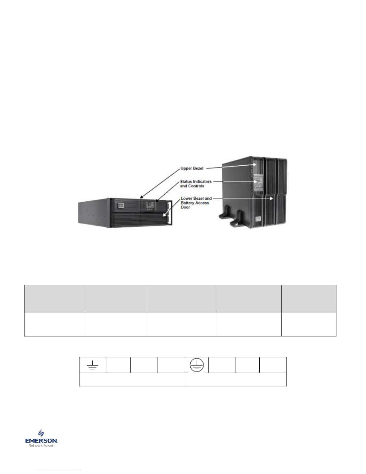
If the installation is in the Tower orientation, locate the support base and stand the UPS up on the support base. Note the
display should be located on the upper half of the unit in the Tower orientation and to rotate the display, grasp the sides
and rotate it 90 degrees clockwise. If the USP is to be installed in a rack enclosure, follow the instructions provided with
the rack mounting hardware for proper installation.
If using an optional POD that was purchased separately, please see instructions shipped with the POD for installation
instructions. This should be done before connecting the UPS to utility power.
The UPS is hardwired input with a conduit entry knockouts provided. Input and output wiring should be installed in
separate conduits. All wiring should be done in accordance to all local and national electrical codes. Before wiring the
UPS ensure that the breaker in the external upstream panelboard is OFF.
Terminal Block Connections
If an optional POD with output receptacles is used, connect the equipment to be protected to the output receptacles.
1 SL-23185QS10_Rev0_09-2012
Page 2
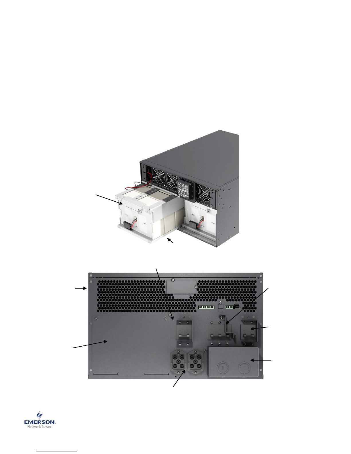
The Liebert® GXT3™ 8000-10000 VA models ship without the internal battery installed. Located the internal battery kit,
Optional POD
Cover
(Replace with POD)
External Battery
Cabinet Connectors
for
GXT3-288RTVBATT
Input / Output
Conduit Box
Input Circuit Breaker
Maintenance
Bypass Breaker
Output Circuit Breaker
Battery Kit Handle
Internal Battery Kit
(1 of 2)
GXT3-288RTBKIT
Liebert GXT3 UPS
GXT3-8000RT208
or
GXT3-10000RT208
model number GXT3-288RTBKIT, and follow these steps to install the battery.
1. Loosen and remove the screws on the battery door and remove the battery door and set aside the screws and
door for reassembly
2. Insert the two battery trays and connect the plugs to the mating receptacles
3. Gently push the battery wiring into the compartment making sure that the wiring will not be pinched when the
battery door is reinstalled.
4. Reinstall the battery door and secure using the screws that were removed in step 1.
5. Locate the plastic bezel from the shipping box and attach the bezel to the UPS taking care to align the fastening
clips on both ends before inserting them into the holes.
6. If your application requires the use of external battery cabinets for longer back up time requirements, connect the
first battery cabinet to the UPS with the cable provided with the battery cabinet. Note: it does not matter which
connector is used on the battery cabinet. If more than one battery cabinet is used the additional cabinets then
connect to the adjoining battery cabinet.
2 SL-23185QS10_Rev0_09-2012
Page 3
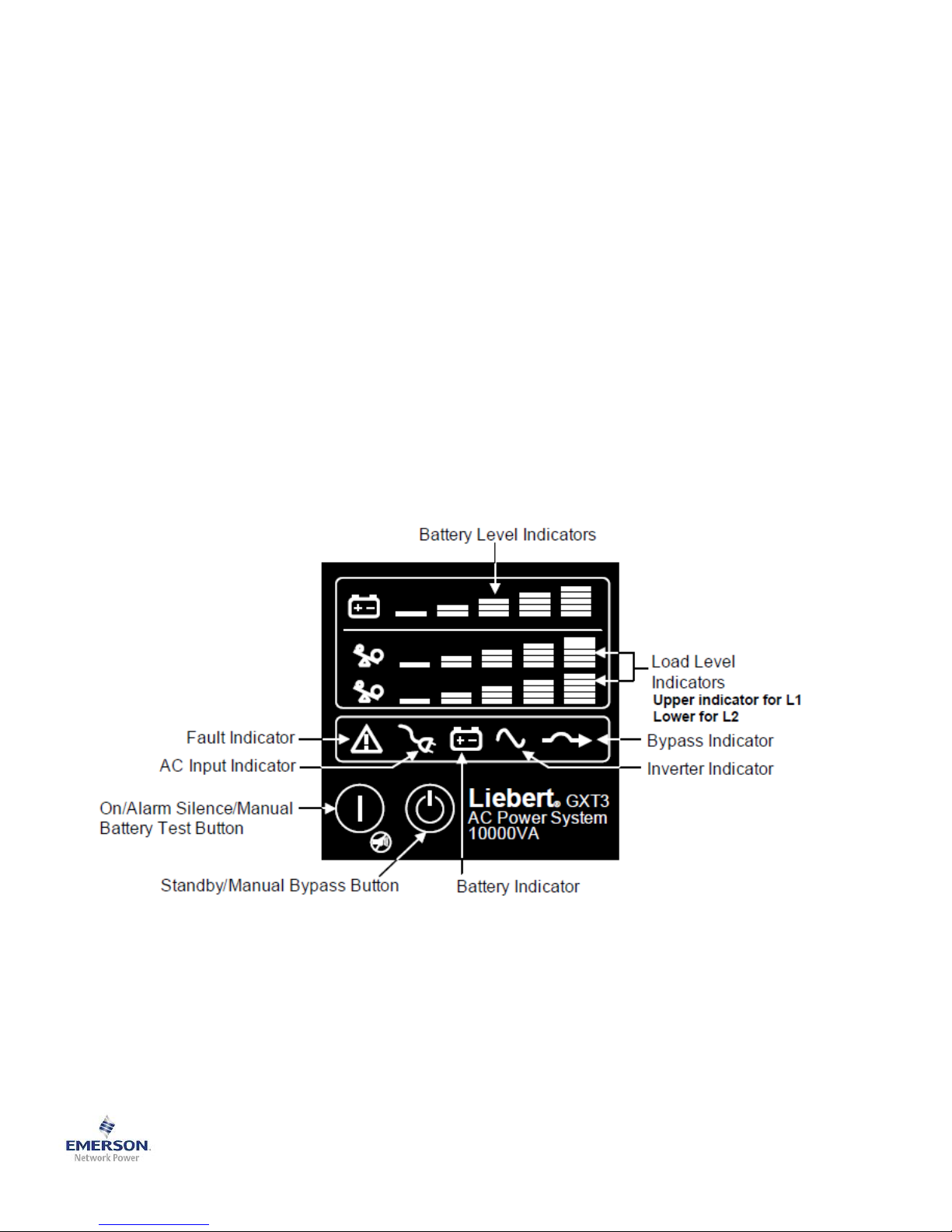
The Liebert® GXT3™ UPS is ready to be powered.
1. Ensure the maintenance bypass breaker is in the open position and that the guard is secured in place.
2. Ensure that the REPO connector on the rear of the unit has a jumper between pins 1-2 of the REPO connector or
properly wired to an Emergency Power Off circuit (normally closed).
3. Install any optional Intellislot communication card into the Intellislot port on the rear of the unit.
4. Ensure the Power Module locking lever is in the locked position. Note: this lever is located on the front of the unit
just to the left of the display (rack orientation) or below the display (tower orientation)
5. Close the input breaker in the panelboard that provides input power to the UPS
6. Close the input breaker on the rear of the UPS unit. Note: the UPS will now have power and the AC Input
indicator on the display should illuminate. The UPS will also begin to charge the internal batteries at this point, so
there will also be battery capacity LEDs illuminated.
7. The Liebert GXT3 UPS has customizable settings that might be required depending on the application. Please
review the CD that ships with the UPS unit for the steps to use the configuration program and make any
necessary changes. Once that is complete, proceed to the next step.
8. Close all output breakers on the rear of the UPS and on the POD (if used) or in an external panelboard (if used)
9. If external battery cabinets are used, close all breakers on the rear of each battery cabinet
10. Press and hold for about 4 seconds, the “ON” button on the UPS display. Note: this will apply power to the output
receptacles via the internal bypass and the bypass indicator will be illuminated along with an audible beep.
11. Over the next several seconds the UPS will perform the self checks and startup routine then automatically
transfer the connected equipment to the inverter power. Once that is complete, the bypass indicator will turn off
and the inverter indicator will illuminate.
The UPS is now running in normal operation mode providing protected, filtered power to the connected equipment.
3 SL-23185QS10_Rev0_09-2012
Page 4
Troubleshooting
Indicator
Diagnosis/Audible alarm
A - E
On bypass from output overload (half-second beep every half-second)
A
On bypass due to over temperature condition (1-second beep every 4 seconds)
B
On bypass due to DC bus overvoltage (1-second beep every 4 seconds)
C
On bypass due to DC/DC power supply failure (1-second beep every 4 seconds)
D
PFC failure (1-second beep every 4 seconds)
E
On bypass due to inverter failure (1-second beep every 4 seconds)
A&B
UPS Failure (includes dual-fan failure, single-fan failure under certain conditions and
battery charger failure) and continuous alarm
A&C
UPS failed battery test (2-second beep every 60 seconds)
A&D
Maintenance bypass switch on (continuous)
A&E
Bypass feedback (1-second beep every 4 seconds)
B&C
REPO (one quarter-second beep at quarter-second intervals)
B&E
Short circuit on the output
C&E
UPS shutdown by command from communication (USB or Liebert IntelliSlot® port)
(no audible alarm)
AC Input Indicator
LED flashing
L-N reverse
Battery Indicator
Flashing
Internal battery source not available (continuous audible alarm); check battery
connection, power down and reboot UPS
Bypass Indicator
Flashing
Utility power voltage or frequency is out of tolerance; bypass is unavailable
United States
1050 Dearborn Drive
P.O. Box 29186
Columbus, OH 43229
800-222-5877
Europe
Via Leonardo Da Vinci 8
Zona Industriale Tognana
35028 Piove Di Sacco (PD) Italy
+39 049 9719 111
Fax: +39 049 5841 257
Asia
29/F, The Orient Square Building
F. Ortigas Jr. Road, Ortigas Center
Pasig City 1605
Philippines
+63 2 687 6615
Fax: +63 2 730 9572
The following symptoms indicate the Liebert® GXT3™ is malfunctioning:
• The relative indicators illuminate, indicating the UPS has detected a problem.
• An alarm buzzer sounds, alerting the user that the UPS requires attention.
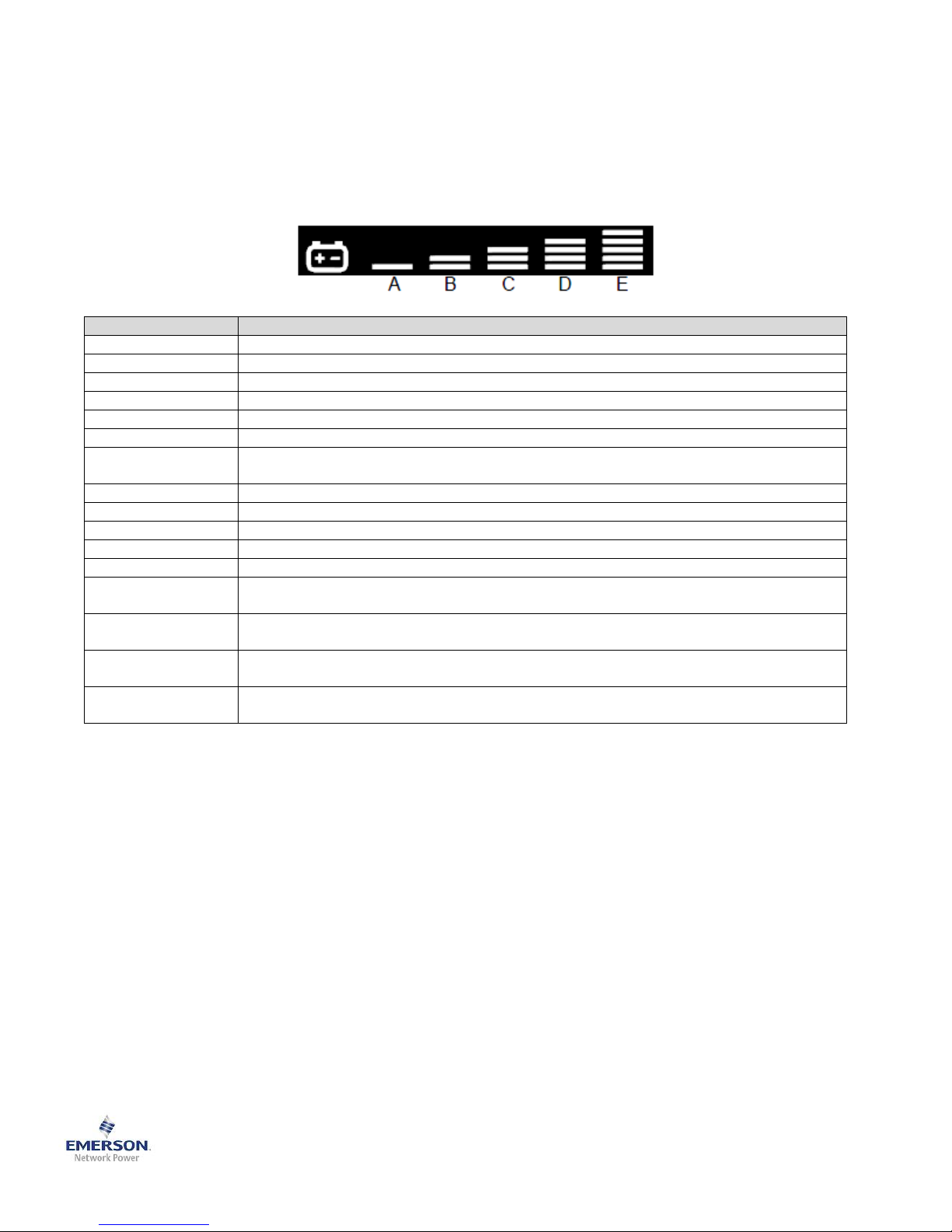
In addition to the fault indicator being illuminated, one or more of LED segments of battery level indicator will also be
illuminated to provide a diagnostic aid to the user, as shown below
The descriptions are listed in the following table
Single-Phase UPS & Server Cabinets Technical Support
[email protected]
800-222-5877
Outside North America: +00800 1155 4499
Emerson Network Power Worldwide Locations
4 SL-23185QS10_Rev0_09-2012
 Loading...