

Page 1

AC Power Systems
For Business-Critical Continuity™
Liebert® GXT2U
™
User Manual - 208V, 2700VA
DISCONTINUED
PRODUCT
Page 2

DISCONTINUED
PRO DU C T
Page 3

i
TABLE OF CONTENTS
IMPORTANT SAFETY INSTRUCTIONS . . . . . . . . . . . . . . . . . . . . . 1
GLOSSARY OF SYMBOLS . . . . . . . . . . . . . . . . . . . . . . . . . . . . 3
INTRODUCTION . . . . . . . . . . . . . . . . . . . . . . . . . . . . . . . . . . . . 4
MAJOR COMPONENTS. . . . . . . . . . . . . . . . . . . . . . . . . . . . . . . 5
Transient Voltage Surge Suppression and EMI/RFI Filters . . . 5
Rectifier/Power Factor Correction (PFC) Circuit . . . . . . . . . . . . 5
Inverter . . . . . . . . . . . . . . . . . . . . . . . . . . . . . . . . . . . . . . . . . . . . . 5
Battery Charger . . . . . . . . . . . . . . . . . . . . . . . . . . . . . . . . . . . . . . 5
DC-to-DC Converter. . . . . . . . . . . . . . . . . . . . . . . . . . . . . . . . . . . 6
Battery . . . . . . . . . . . . . . . . . . . . . . . . . . . . . . . . . . . . . . . . . . . . . 6
Dynamic Bypass. . . . . . . . . . . . . . . . . . . . . . . . . . . . . . . . . . . . . . 6
Liebert GXT2U—Rear View . . . . . . . . . . . . . . . . . . . . . . . . . . . . 7
INSTALLATION. . . . . . . . . . . . . . . . . . . . . . . . . . . . . . . . . . . . . 8
Preparation. . . . . . . . . . . . . . . . . . . . . . . . . . . . . . . . . . . . . . . . . . 8
Tower UPS Installation . . . . . . . . . . . . . . . . . . . . . . . . . . . . . . . . 8
Rack-Mount UPS Conversion and Installation . . . . . . . . . . . . . 9
External Battery Cabinet Installation . . . . . . . . . . . . . . . . . . . 12
CONTROLS AND INDICATORS. . . . . . . . . . . . . . . . . . . . . . . . . 14
ON/Alarm Silence/Manual Battery Test Button . . . . . . . . . . . 14
Standby/ Manual Bypass Button. . . . . . . . . . . . . . . . . . . . . . . . 15
Load/Battery Level Indicators (4 Green, 1 Amber) . . . . . . . . . 15
Fault Indicator LED (Red). . . . . . . . . . . . . . . . . . . . . . . . . . . . . 15
Bypass Indicator LED (Amber) . . . . . . . . . . . . . . . . . . . . . . . . . 15
UPS ON Indicator LED (Green) . . . . . . . . . . . . . . . . . . . . . . . . 15
Battery Indicator LED (Amber) . . . . . . . . . . . . . . . . . . . . . . . . 15
AC Input Indicator LED (Green). . . . . . . . . . . . . . . . . . . . . . . . 15
Output Voltage Selection. . . . . . . . . . . . . . . . . . . . . . . . . . . . . . 16
DISCONTINUED
PRO DU C T
Page 4

ii
OPERATING INSTRUCTIONS . . . . . . . . . . . . . . . . . . . . . . . . . . 17
Normal Mode Operation . . . . . . . . . . . . . . . . . . . . . . . . . . . . . . 17
Bypass Mode Operation . . . . . . . . . . . . . . . . . . . . . . . . . . . . . . . 17
Battery Mode Operation . . . . . . . . . . . . . . . . . . . . . . . . . . . . . . 18
Battery Recharge Mode . . . . . . . . . . . . . . . . . . . . . . . . . . . . . . . 18
COMMUNICATIONS . . . . . . . . . . . . . . . . . . . . . . . . . . . . . . . . 19
Communications Interface Port . . . . . . . . . . . . . . . . . . . . . . . . 19
Pins 4 & 5 - Remote Shutdown on Battery. . . . . . . . . . . . . . . . 19
Pins 5 & 6 - Any-Mode Shutdown . . . . . . . . . . . . . . . . . . . . . . . 20
Auto-Enable Output. . . . . . . . . . . . . . . . . . . . . . . . . . . . . . . . . 20
Pin 6 Logic . . . . . . . . . . . . . . . . . . . . . . . . . . . . . . . . . . . . . . . . 20
UPS Intelligent Communications . . . . . . . . . . . . . . . . . . . . . . . 21
CONFIGURATION PROGRAM . . . . . . . . . . . . . . . . . . . . . . . . . 22
Liebert GXT2U Configuration Program Abilities . . . . . . . . . . 22
What You Will Need . . . . . . . . . . . . . . . . . . . . . . . . . . . . . . . . 22
MAINTENANCE . . . . . . . . . . . . . . . . . . . . . . . . . . . . . . . . . . . 23
Battery Replacement . . . . . . . . . . . . . . . . . . . . . . . . . . . . . . . . . 23
Internal Battery Replacement Procedures . . . . . . . . . . . . . . . 24
TROUBLESHOOTING . . . . . . . . . . . . . . . . . . . . . . . . . . . . . . . 25
SPECIFICATIONS . . . . . . . . . . . . . . . . . . . . . . . . . . . . . . . . . . 29
Battery Cabinet Specifications . . . . . . . . . . . . . . . . . . . . . . . . . 30
Battery Run Times. . . . . . . . . . . . . . . . . . . . . . . . . . . . . . . . . . . 31
Product Warranty Registration. . . . . . . . . . . . . . . . . . . . . . . . . 32
DISCONTINUED
PRO DU C T
Page 5

1
IMPORTANT SAFETY INSTRUCTIONS
SAVE THESE INSTRUCTIONS
This manual contains important safety instructions. Read all safety,
installation, and operating instructions before operating the Uninterruptible
Power System (UPS). Adhere to all warnings on the unit and in this manual.
Follow all operating and user instructions. Individuals without previous
training can install and operate this equipment.
It is not intended for use with life support and other designated “critical”
devices. Maximum load must not exceed that shown on the UPS rating label.
The UPS is designed for data processing equipment. If uncertain, consult your
local dealer or Liebert representative.
This UPS is designed for use on a properly grounded (earthed), 50Hz or 60 Hz,
208V supply (programmable for 200, 208, 220, 230, and 240VAC output).
Installation instructions and warning notices are located in this manual.
ELECTROMAGNETIC COMPATIBILITY—The Liebert GXT2U™ Series
complies with the limits for a CLASS A DIGITAL DEVICE, PURSUANT TO
Part 15 of FCC rules. Operation is subject to the following two conditions: (1)
This device may not cause harmful interference, and (2) this device must
accept any interference received, including interference that may cause
undesired operation. Operating this device in a residential area is likely to
cause harmful interference that users must correct at their own expense.
Operate the UPS in an indoor environment only in an ambient temperature
range of 32°F to +104°F (0°C to +40°C). Install it in a clean environment, free
from moisture, flammable liquids, gases and corrosive substances.
This UPS contains no user serviceable parts except the internal battery pack.
The UPS ON/Standby push buttons do not electrically isolate internal parts.
Under no circumstances attempt to gain access internally other than to
replace the batteries due to risk of electric shock or burn. Do not continue to
use the UPS if the front panel indications are not in accordance with these
operating instructions or if the UPS performance alters in use. Refer all faults
to your local dealer, Liebert representative or the Liebert Worldwide Support
Group.
Servicing of batteries should be performed or supervised by personnel
knowledgeable of batteries and the required precautions. Keep unauthorized
personnel away from the batteries. PROPER DISPOSAL OF BATTERIES IS
REQUIRED. REFER TO YOUR LOCAL LAWS AND REGULATIONS FOR
BATTERY DISPOSAL REQUIREMENTS.
Never block or insert any object into the ventilation holes or other openings of
the UPS.
!
WARNING
Opening or removing the cover may expose you to lethal voltages
within this unit even when it is apparently not operating and the
input wiring is disconnected from the electrical source. Observe all
cautions and warnings in this manual. Failure to do so MAY result
in serious injury or death. Refer all UPS and battery service to
qualified service personnel. Do not attempt to service this product
yourself. Never work alone.
DISCONTINUED
PRO DU C T
Page 6

2
DO NOT CONNECT equipment that could overload the UPS or demand halfwave rectification from the UPS, for example: electric drills, vacuum cleaners,
laser printers or hairdryers.
Storing magnetic media on top of the UPS may result in data loss or
corruption.
Turn the UPS off and isolate the UPS before cleaning; use only a soft cloth,
never liquid or aerosol cleaners. Keep the front and rear vents free of dust
accumulation that could restrict airflow.
When replacing batteries, replace with the same Liebert authorized
replacement battery kits.
!
CAUTION
Do not dispose of battery or batteries in a fire. The battery may
explode.
Do not open or mutilate the battery or batteries. Released
electrolyte is harmful to skin and eyes. It may be toxic.
!
CAUTION
A battery can present a risk of electrical shock and high short
circuit current. The following precautions should be observed when
working on batteries:
• Remove watches, rings, and other metal objects.
• Use tools with insulated handles.
DISCONTINUED
PRO DU C T
Page 7

3
GLOSSARY OF SYMBOLS
Risk of electrical shock
Indicates caution followed by important instructions
AC input
AC output
Requests the user to consult the manual
Indicates the unit contains a valve-regulated lead acid battery
Recycle
DC voltage
Equipment grounding conductor
Bonded to ground
AC voltage
ON
Standby
i
DISCONTINUED
PRO DU C T
Page 8

4
INTRODUCTION
Congratulations on your choice of the Liebert GXT2U™ Uninterruptible
Power System (UPS). It provides conditioned power to microcomputers and
other sensitive electronic equipment.
Upon generation, AC power is clean and stable. However, during transmission
and distribution it may be subject to voltage sags, spikes, or complete power
failure that may interrupt computer operations, cause data loss, or even
damage equipment. The Liebert GXT2U protects equipment from these
disturbances.
The Liebert GXT2U is rated for 2700 VA, 1890 watts. Complete model
specifications appear at the end of this manual.
The Liebert GXT2U is a compact, “on-line” UPS. An on-line UPS continuously
conditions and regulates its output voltage, whether utility power is present
or not. It supplies connected equipment with clean sine wave power. Sensitive
electronic equipment operates best from sinewave power.
For ease of use, the Liebert GXT2U features a light-emitting diode (LED)
display to indicate either load percentage or battery capacity depending upon
the mode of operation. It also provides self-diagnostic tests, a combination ON/
Alarm Silence/Manual Battery Test button, a Standby button, user
configurable program, and two levels of alarms when the unit is operating on
battery.
The Liebert GXT2U has an interface port for communication between the UPS
and a network server or other computer systems. This port provides detailed
operating information including voltages, currents, and alarm status to the
host system when used in conjunction with Liebert MultiLink™ software.
Liebert MultiLink software can also remotely control UPS operation.
DISCONTINUED
PRO DU C T
Page 9

5
MAJOR COMPONENTS
Transient Voltage Surge Suppression and EMI/RFI Filters
These UPS components provide surge protection and filter both
electromagnetic interference (EMI) and radio frequency interference (RFI).
They minimize any surges or interference present in the utility line and keep
the sensitive equipment protected.
Rectifier/Power Factor Correction (PFC) Circuit
In normal operation, the rectifier/power factor correction (PFC) circuit
converts utility AC power to regulated DC power for use by the inverter while
ensuring that the waveshape of the input current used by the UPS is near
ideal. Extracting this sinewave input current achieves two objectives:
• The utility power is used as efficiently as possible by the UPS.
• The amount of distortion reflected on the utility is reduced.
This results in cleaner power being available to other devices in the building
not being protected by the Liebert GXT2U.
Inverter
In normal operation, the inverter utilizes the DC output of the power factor
correction circuit and inverts it into precise, regulated sinewave AC power.
Upon a utility power failure, the inverter receives its required energy from the
battery through the DC to DC converter. In both modes of operation, the UPS
inverter is on-line and continuously generating clean, precise, regulated AC
output power.
Battery Charger
The battery charger utilizes energy from the utility power and precisely
regulates it to continuously “float charge” the batteries. The batteries are
being charged whenever the Liebert GXT2U is plugged in, even when the UPS
is not turned on.
Input Output
Inverter
Battery
Battery
Charger
DC to DC
Converter
Rectifier
/PFC
TVSS &
EMI/RFI
Filters
L1
L2
G
L1
L2
G
Dynamic
Bypass
DISCONTINUED
PRO DU C T
Page 10

6
DC-to-DC Converter
The DC-to-DC converter utilizes energy from the battery system and raises
the DC voltage to the optimum operating voltage for the inverter. This allows
the inverter to operate continuously at its optimum efficiency and voltage,
thus increasing reliability.
Battery
The Liebert GXT2U utilizes valve-regulated, nonspillable lead acid batteries.
To maintain battery design life, operate the UPS in an ambient temperature
of 68°F to 77°F (20°C to 25°C). Optional external battery cabinets are
available to extend battery run times.
Dynamic Bypass
The Liebert GXT2U provides an alternate path for utility power to the
connected load in the unlikely event of a UPS malfunction. Should the UPS
have an overload, overtemperature, or UPS failure condition, the UPS
automatically transfers the connected load to bypass. Bypass operation is
indicated by an audible alarm and illuminated amber Bypass LED (other
LEDs may be illuminated to indicate the diagnosed problem). To manually
transfer the connected load from the inverter to bypass, press the Standby
button once.
NOTE
The bypass power path does NOT protect the connected equipment
from disturbances on the utility supply.
DISCONTINUED
PRO DU C T
Page 11

7
Liebert GXT2U—Rear View
Input Circuit
Breaker
(20 amp)
AC Input
(L6-20)
Output
Receptacles
(L6-15R)
External
Battery
Connector
Cooling
Fans
Liebert
IntelliSlot
®
Port
DB-9
Communications Port
Output
Receptacle
(L6-20R)
Support
Base
DISCONTINUED
PRO DU C T
Page 12

8
INSTALLATION
Preparation
1. Visually inspect the UPS for freight damage. Report damage to the carrier
and your local dealer or Liebert representative.
2. Decide where to place the Liebert GXT2U. Install the UPS indoors in a controlled environment, where it cannot be accidentally turned off. Place it in
an area of unrestricted airflow around the unit, away from water, flammable liquids, gases, corrosives, and conductive contaminants. Maintain a
minimum clearance of 4 inches (100mm) in the front and rear of the UPS.
Maintain an ambient temperature range of 32°F to 104°F (0°C to 40°C).
3. The Liebert GXT2U may be installed in either a tower configuration or in a
rack, depending on available space and use considerations. Determine the
type of installation and follow the appropriate instructions in either Tower
UPS Installation or Rack-Mount UPS Conversion and Installation.
Tower UPS Installation
When using the Liebert GXT2U in a tower configuration, use the included
support base (shown below, left) to stabilize the UPS.
If any battery cabinets are added, they will include spacers to accommodate
the additional cabinets (shown below, right).
!
CAUTION
The UPS is heavy (see Specifications section). Take proper
precautions when lifting or moving it.
NOTE
UPS operation in temperatures above 77°F (25°C) reduces battery
life.
Support base Spacers added to support
base to accommodate
additional battery cabinets
DISCONTINUED
PRO DU C T
Page 13
9
Rack-Mount UPS Conversion and Installation
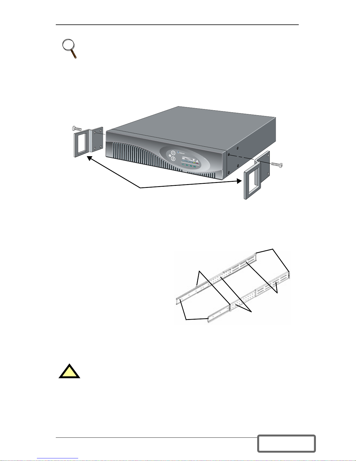
1. For slide rail installations, first remove the top/side fin. Slide the
top/side fin forward, then lift it up to remove. If desired, install the optional
rack mount handles that were shipped with the UPS.
Securing hardware and slide rails are sold separately. Contact your local
dealer or Liebert representative for these additional options and any assistance needed.
2. Unpack the two (2) rack-mounting bracket assemblies and
mounting hardware from the
rack-mounting kit
(P/N: RMKIT18-32). Bracket
assemblies are interchangeable
between left-hand or right-hand.
Remove inner member of each
bracket assembly as shown at
right by extending it to its outermost position, depressing the
retaining latch and then pulling
inner member from bracket
assembly.
3. Determine the height position
inside the rack enclosure where you want to mount the UPS or battery cabinet.
NOTE
When rack mounted, the UPS must be supported by a shelf, brackets
or slide rails on each side. The rack mount handles WILL NOT
support the weight of the UPS. They are used to move the UPS into
and out of the rack.
!
CAUTION
Reduce risk of tipping the rack enclosure by placing UPS or
battery cabinet in the lowest possible rack position.
+
–
AC INPUT BATTERY UPS ON BYPASS
UPStation GXT
Optional rack mount handles
Return
flanges
Inner
members
Retaining
latches
Front
members
Rear
members
DISCONTINUED
PRO DU C T
Page 14
10
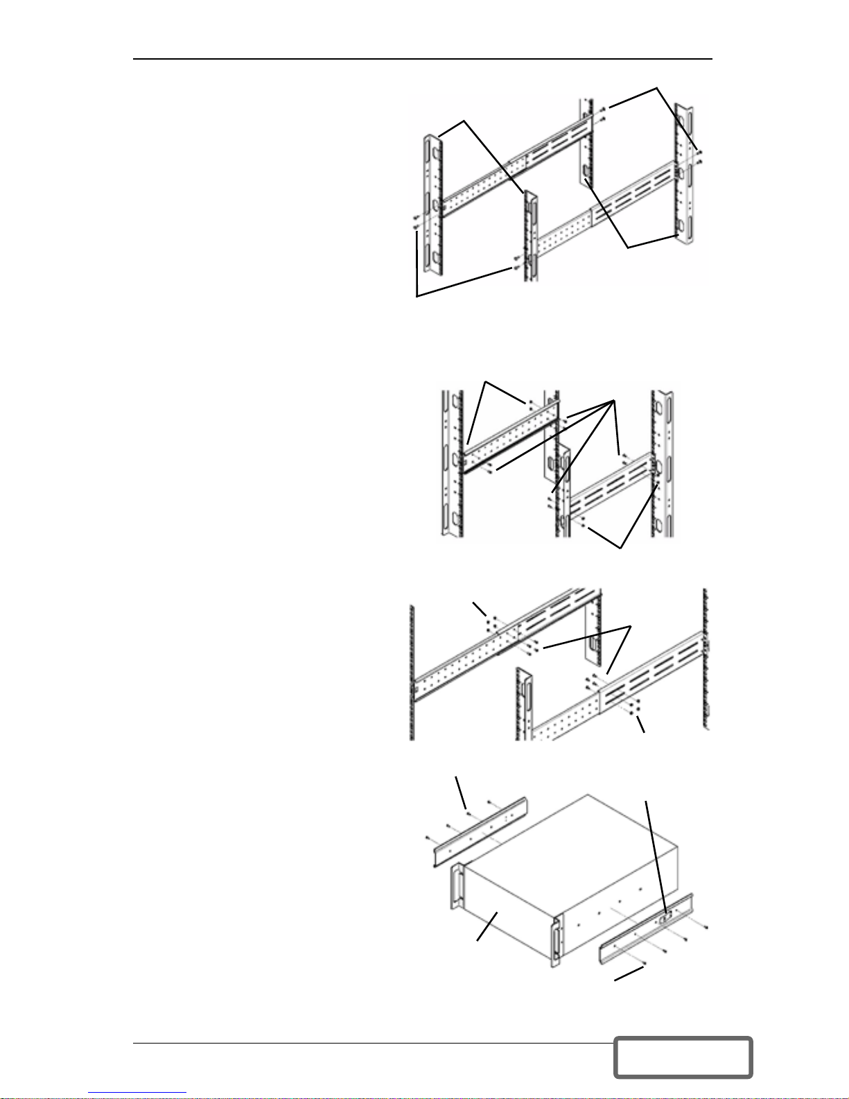
Install rear member of each
bracket assembly into rack enclosure with two (2) M5 screws provided in this kit. (See figure at
right.) Return flanges on bracket
assembly fit to the inside of rack
mounting rails. Insert screws
loosely (finger-tight) into top and
bottom holes of return flange on
rear member. Extend bracket
assembly by sliding front member forward until it touches the
front rack mounting rail. Insert
two (2) M5 screws loosely (fingertight) into top and bottom holes
of return flange on each front member. Make sure bracket assemblies are at
the same mounting height on all four (4) rack mounting rails.
4. Locate eight (8) M4 screws and
eight (8) M4 nuts from hardware
pack in this kit. Each nut has a
locking, nylon insert that begins
gripping the screw when it is
halfway tight. Make sure to
tighten nut and screw completely
to assure locking action. Fasten
rear member and front member
together using four (4) screws
and four (4) nuts per bracket
assembly as shown in the figures
at right. For maximum support,
locate fasteners for each bracket
assembly as far apart as possible,
depending on rack depth, while
still joining both members (See
figures at right). Check alignment of bracket assemblies and
TIGHTEN ALL SCREWS FROM
STEPS 3 and 4.
5. Prepare the UPS or battery cabinet (the “equipment”) for rack
mounting by following instructions
in the equipment’s user manual.
The equipment may require additional parts to be added or parts to
be removed for rack mounting.
After it is prepared, lay equipment
in rack-mounting position. Fasten
inner members from Step 2 to the
equipment on both sides as shown
in the figure at right with (8) M4
screws provided in this kit. Make
sure retaining latch is near the rear
of the equipment as shown in the
figure at right.
M5 screws
M5 screws
Front rack
mounting rails
Rear rack
mounting
rails
32" rack
depth
M4 nuts
M4 nuts
M4
screws
18" rack
depth
M4 nuts
M4 nuts
M4
screws
UPS or battery
cabinet
Front
M4 screws
M4 screws
Retaining
latch
DISCONTINUED
PRO DU C T
Page 15
11
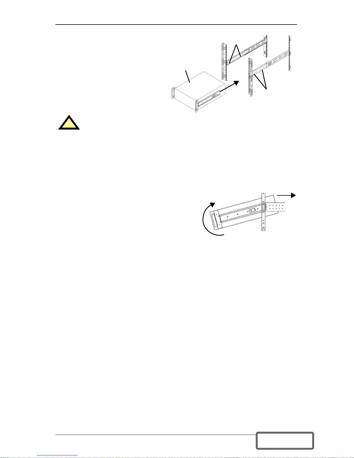
6. Open grease packet provided
in this kit. Apply a 1" long
bead of grease four (4) places
inside the bottom, curved
tracks of front members as
shown at right. The grease
will allow the equipment to
slide into the bracket assemblies more easily.
7. Insert the equipment, with inner members attached from Step 5, into
bracket assemblies by inserting top and bottom edges of inner members
into the top and bottom, curved tracks of front members and sliding the
equipment into rack (see figure in Step 6). Ends of inner members are
tapered to allow rear of the equipment to be angled upward before insertion, if space allows.
Then the rear, bottom edges of inner members can be placed into front edge of bottom
tracks, and the front of the equipment can
be tipped up into horizontal position to
insert the top edges of inner members
before sliding the equipment into rack (see
figure at right). The equipment should
move smoothly into bracket assemblies. If not, recheck alignment of front
and rear members from Steps 3 and 4.
8. Secure front of the equipment to rack mounting rails to prevent the equipment from sliding out of position. If securing holes are provided on front of
the equipment that align with the center holes on return flange of front
members, you can use the four (4) extra M5 screws provided in this kit to
secure the equipment. Otherwise, the equipment should be secured to front
of rack mounting rails with four (4) customer-supplied fasteners.
!
CAUTION
Lifting equipment into rack may be a two-person job, depending
on weight of equipment. See equipment’s user manual.
UPS or
battery
cabinet
Apply
grease
(inside)
Apply
grease
DISCONTINUED
PRO DU C T
Page 16
12
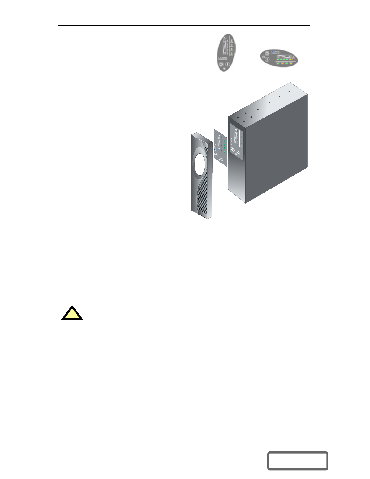
9. To orient the display for horizontal
viewing, remove the front plastic
bezel by pulling forward evenly on
both sides. The unit has two front
panel overlays. Remove the outer
overlay (used for tower installation).
This reveals a horizontally oriented
front panel overlay for rack mounting. Snap the front bezel back into
place.
10.Once the UPS is installed in the
rack, the load may be connected.
Ensure the load equipment is
turned off; plug all loads into the
output receptacles on the rear of the
UPS.
11.Plug the UPS into a dedicated wall
receptacle properly protected by a
circuit breaker or fuse in accordance
with national and local electrical
codes. Use a 20 amp rated device for
the 2700VA, 208 V unit. The wall
receptacle must be grounded.
12.Turn ON the UPS by pressing the
ON button; then turn on the connected load equipment. The UPS is now providing conditioned power to
your equipment.
External Battery Cabinet Installation
Optional Liebert external battery cabinets may be connected to the UPS to
provide additional battery run time. External battery cabinets are designed to
be placed all on one side of the UPS or stacked beneath the UPS. There is no
limit to the number of external battery cabinets that can be used but each
cabinet will increase the battery recharge time.
1. Visually inspect the external battery cabinet for freight damage. Report
damage to the carrier and your local dealer or Liebert representative.
2. For slide rail installations, first remove the top/side fin. Top/side fin slides
forward and then lift up to remove. Optional rack-mount handles are
shipped with the external battery cabinet and may be installed at this time
if desired.
3. Securing hardware and slide rails are sold separately. Please contact your
local dealer or Liebert representative for these additional options and any
assistance needed. Fasten the slides into position with the screws per the
instructions included with the slide rails.
!
CAUTION
The external battery cabinet(s) are heavy (see Specifications
section). External battery cabinets can be used in rack-mount or
tower configuration. Take proper precautions when lifting them.
+
–
UPStation GXT
AC INPUT BATTERY UPS ON BYPASS
+
–
UPStation GXT
AC INPUT BATTERY UPS ON BYPASS
Vertical
overlay
for
tower
UPS
Horizontal
overlay
DISCONTINUED
PRO DU C T
Page 17
13
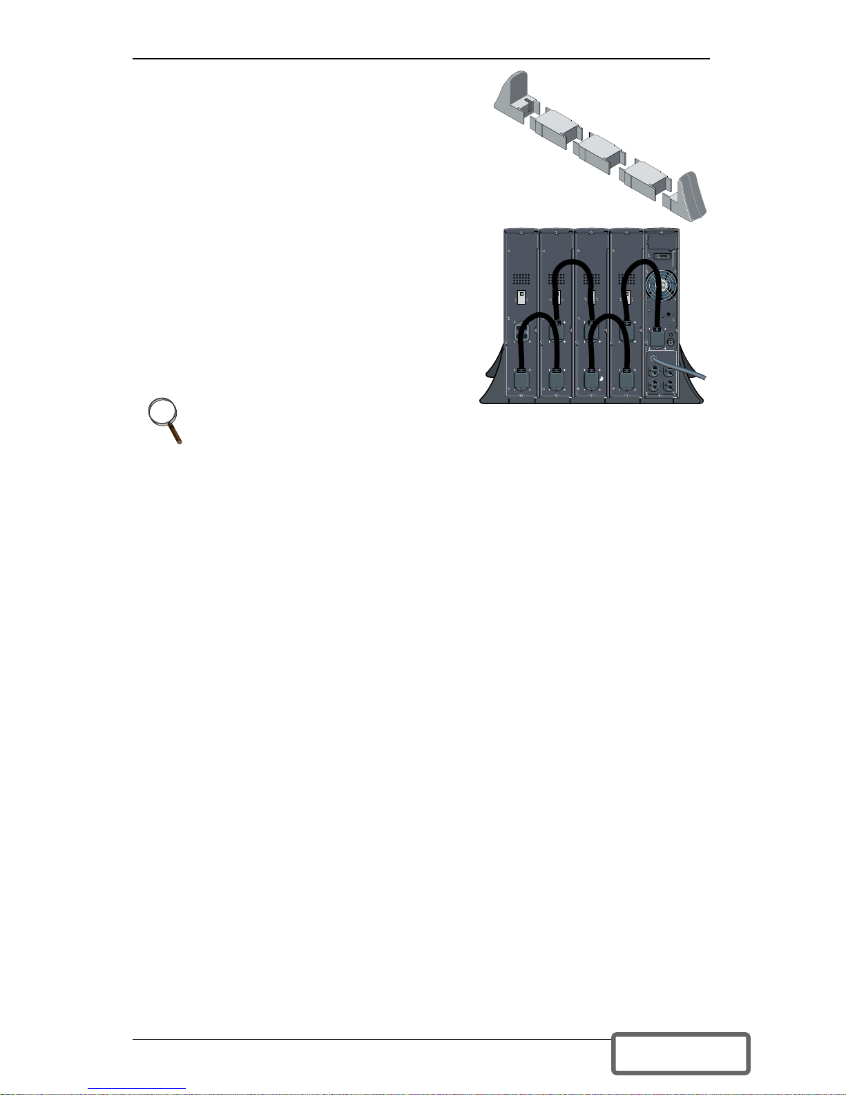
4. Use the enclosed support bases for the tower
option to prevent tip-over. One additional set
of support base extensions ships with each
external battery cabinet.
5. Connect the supplied external battery cabinet cable to the rear of the external battery
cabinet, then to the rear of the UPS.
6. Turn ON the battery breaker on the rear of
the external battery cabinet.
7. The UPS is now equipped with additional
backup battery run time. For approximate
battery run times, refer to the Battery
Run Times charts in this manual.
NOTE
You must use the included Configuration Program to specify the
number of external battery cabinets connected to the UPS. For more
information, see Configuration Program on page 22.
DISCONTINUED
PRO DU C T
Page 18
14
CONTROLS AND INDICATORS
ON/Alarm Silence/Manual Battery Test Button
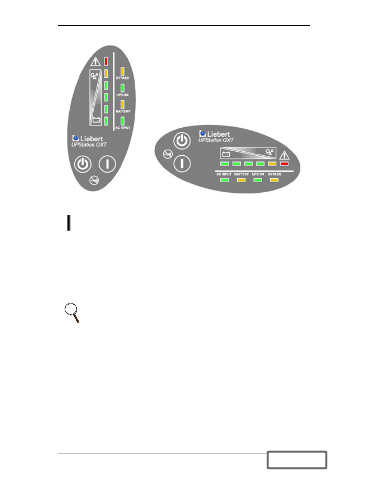
This button controls output power to connected load(s) and has three
functions:
• ON
• Alarm Silence
• Manual Battery Test
ON - Pressing this button will start up the UPS in order to provide
conditioned and protected power.
Alarm Silence - To silence alarms, press this button for at least one second.
After the alarm is silenced, the Liebert GXT2U will reactivate the alarm
system to alert of additional problems.
Manual Battery Test - To initiate a manual battery test, press the ON
button for at least one second while operating from utility power with no
alarm conditions present.
• If only three of the five Battery LEDs illuminate, allow the UPS to recharge
the batteries for 24 hours.
• After 24 hours, retest the batteries.
• After the batteries have been retested, if only three of the five Battery
LEDs illuminate, contact your local dealer, Liebert representative or Liebert Worldwide Support Group.
NOTE
The LOW BATTERY and BYPASS reminder alarms CANNOT be
silenced.
All LEDs illuminated
for illustrative purposes only.
DISCONTINUED
PRO DU C T
Page 19
15
Standby/ Manual Bypass Button
This button controls output power to connected load(s) and has dual
functions: Standby and Manual Bypass.
Load/Battery Level Indicators (4 Green, 1 Amber)
The load/battery level indicators have dual functions. During normal mode
operation LED indicators display the approximate electrical load placed upon
the UPS; and during battery mode operation LED indicators display
approximate battery capacity.
The Liebert GXT2U is equipped with automatic and remote battery test
features. The automatic test occurs every 14 days (this option is user
configurable) if utility has not been interrupted. Should the battery fail this
test, the red Fault indicator LED along with the A and C diagnostic LEDs will
illuminate and an alarm will sound (refer to Troubleshooting section). The
remote test feature functions with Liebert MultiLink 3 software and can
remotely initiate the battery test.
Fault Indicator LED (Red)
The Fault indicator LED is illuminated if the UPS has detected a problem.
Also, one or more of the load/battery level indicators may be illuminated (refer
to Troubleshooting section).
Bypass Indicator LED (Amber)
The Bypass indicator LED is illuminated when the UPS is operating from
bypass power. An alarm will sound indicating the UPS detected a problem, or
the manual bypass function has been activated.
UPS ON Indicator LED (Green)
The UPS ON indicator LED is illuminated when the UPS inverter is operating
and supplying power to your connected loads.
Battery Indicator LED (Amber)
The Battery indicator LED is illuminated when the UPS is operating on
battery.
AC Input Indicator LED (Green)
The AC Input indicator LED is illuminated when utility power is available
and within the input specifications.
!
CAUTION
While the UPS is in Normal Mode operation, pressing the Standby/
Manual Bypass button once will put the UPS into Bypass Mode.
Once the UPS is in Bypass Mode operation, press the Standby/
Manual Bypass button two distinct times (for about one second each
time) to turn off the UPS. Perform all necessary shutdown
procedures on connected loads before turning off the UPS.
DISCONTINUED
PRO DU C T
Page 20

16
Output Voltage Selection
The Output Voltage is user configurable and is designed to allow selecting or
changing the desired output voltage to match the utility via the Liebert
GXT2U Configuration Program provided with the UPS. The settings to choose
from are 200, 208, 220, 230, and 240 VAC output. The factory default setting
is 208 VAC.
!
CAUTION
Never change the voltage settings while the UPS is ON and
powering connected loads.
NOTE
Setting output voltage to 200 VAC will cause the UPS unit to be
derated to 2400 VA, 1680 watts.
DISCONTINUED
PRO DU C T
Page 21
17
OPERATING INSTRUCTIONS
Normal Mode Operation
During normal operation, utility
power provides energy to the
UPS. The filters, power factor
correction circuit and the
inverter process this power to
provide computer grade power to
connected loads. The UPS
maintains the batteries in a fully
charged state.
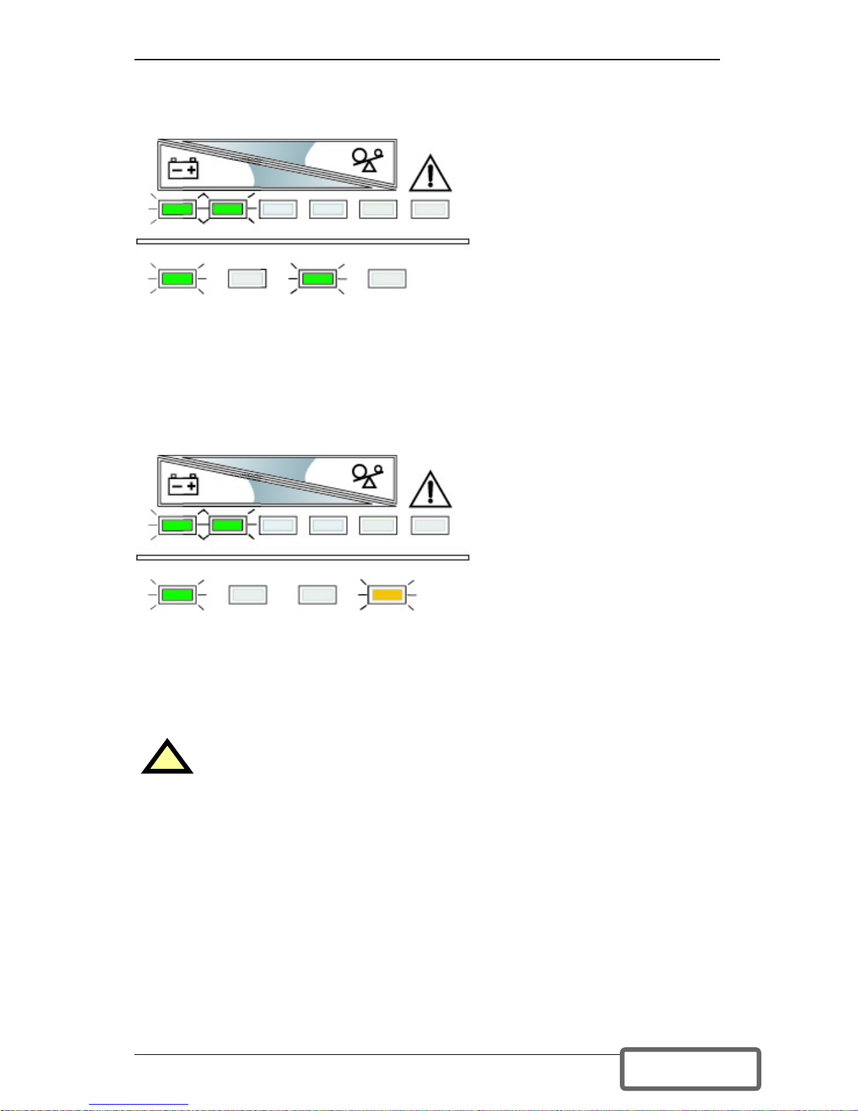
The four green load level LEDs
indicate an approximate level of load in 25% increments. If the UPS becomes
loaded beyond full rating, the fifth (amber) LED indicator will illuminate and
the UPS will sound an audible alarm. The display template indicates the
percentage of load (26-50% of load shown in the example above) on the UPS
output.
Bypass Mode Operation
Bypass mode occurs when the
OFF button is pressed once
while the UPS is in Normal
Mode. During bypass operation,
utility power provides energy to
the UPS. The utility power
bypasses the inverter and
provides power for the connected
load.
The four green load level LEDs
indicate an approximate level of load in 25% increments. If the UPS becomes
loaded beyond full rating, the fifth (amber) LED indicator will illuminate and
the UPS will sound an audible alarm. The display template indicates the
percentage of load (26-50% of load shown in the example above) on the UPS
output.
!
CAUTION
Turning OFF the UPS while in bypass mode will result in loss of
output power.
Normal Mode Operation at 26-50%
AC INPUT BATTERY UPS ON BYPASS
Bypass Mode Operation at 26-50%
AC INPUT BATTERY UPS ON BYPASS
DISCONTINUED
PRO DU C T
Page 22
18
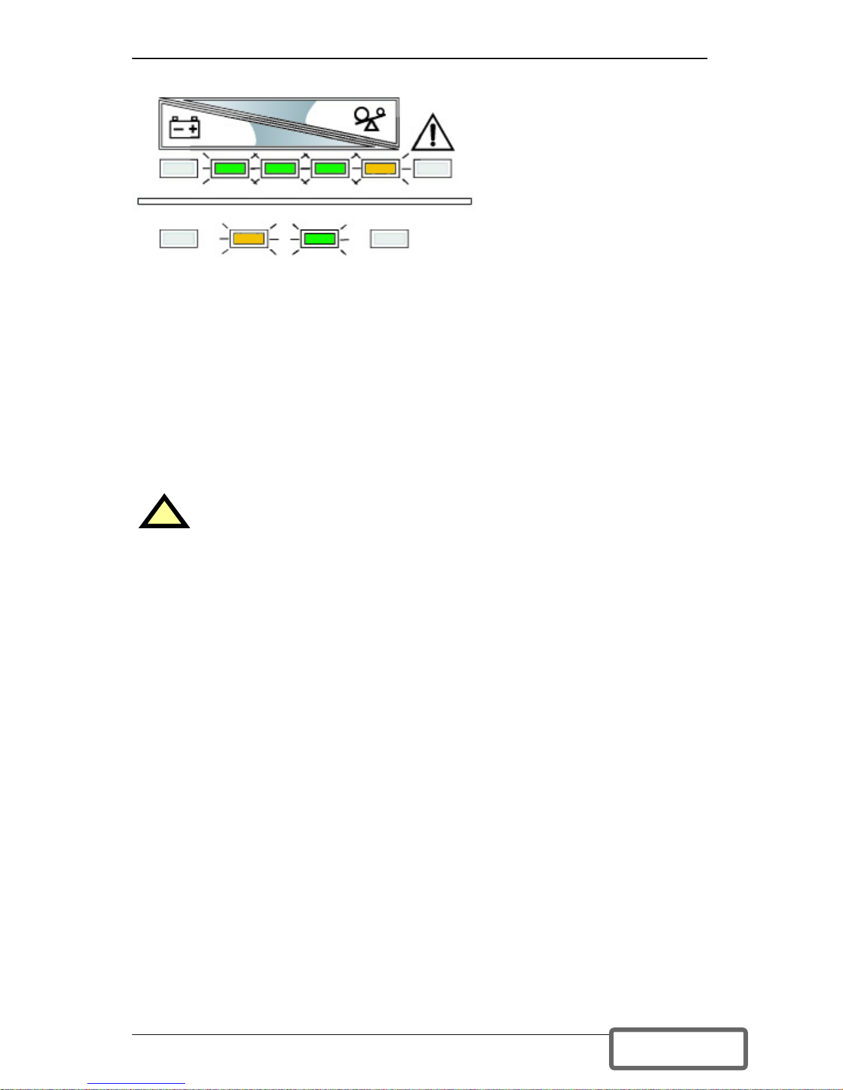
Battery Mode Operation
Battery mode occurs in event
of an extreme input voltage
condition or complete utility
failure. The battery system
supplies power through the DC
to DC converter to the inverter
to generate power for the
connected load.
During battery mode an alarm
sounds every 10 seconds. This
will change to two beeps every
5 seconds when the battery runs low (approximately 2 minutes remaining, but
this is user configurable). The AC Input LED will extinguish, and the Battery
LED will illuminate to warn that a utility problem has occurred. Each battery
level indicator represents a 20% capacity level. As capacity decreases, fewer
indicators remain illuminated. Refer to Troubleshooting section.
For approximate battery run times, refer to the Battery Run Times charts in
this manual. These times are approximates based on resistive load and an
ambient temperature of 77°F (25°C). To increase this time, turn off nonessential pieces of equipment (such as idle computers and monitors) or add the
optional external battery cabinet.
Battery Recharge Mode
Once utility power is restored, the UPS resumes normal operation. At this
time, the Battery Charger begins recharging.
!
CAUTION
Turning OFF the UPS while in battery mode will result in loss of
output power.
Battery Mode Operation at 80-61%
AC INPUT BATTERY UPS ON BYPASS
DISCONTINUED
PRO DU C T
Page 23
19
COMMUNICATIONS
Communications Interface Port
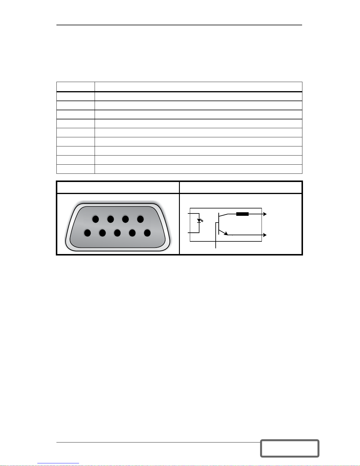
The Liebert GXT2U UPS has a standard DB-9 serial port female connector
located on the rear of the UPS unit. Several signals are provided on this port
and are assigned as follows:
* Maximum voltage and current on pins 1, 7, 8, and 9 is 60VDC; 10.0 mA.
Pins 4 & 5 - Remote Shutdown on Battery
1. This pin is functional only when the UPS is in battery mode. If the UPS is
being powered by the utility, Pin 4 will ignore any signal on this pin.
2. Pin 4 requires a 5-12 VDC signal to shutdown. This normally comes form
the serial port using Liebert’s contact closure cable. It cannot be used with
just a contact closure unless the relay is used to switch a voltage source. A
5-12 VDC signal for 1.5 seconds or greater is required to signal a shutdown.
Signals for less than 1.5 seconds will be ignored. After Pin 4 receives a shutdown signal for 1.5 seconds, the command cannot be canceled.
3. A battery shutdown signal on Pin 4 will NOT cause an immediate shut-
down. A shutdown signal will start a 2-minute shutdown timer. The timer
cannot be stopped. After 2 minutes, the UPS will shut down.
4. If the utility returns during the 2-minute timer countdown, the shutdown
timer will continue until the end of 2 minutes and the UPS will turn OFF.
The UPS must remain OFF for at least 10 seconds even if AC input power
returns before the UPS turns OFF. This serves to reset and restart the
server.
Whether the UPS turns back ON when power is restored depends on the autorestart setting: enabled or disabled.
If the auto-restart is disabled, the UPS will not restart after performing the
2-minute shutdown delay.
Pin Assignment Description
1 Low Battery (open collector)
2 UPS TxD (typical RS-232 levels)
3 UPS RxD (typical RS-232 levels)
4 Remote Shutdown (5-12VDC, 10-24 mA max); battery operation
5 Common
6 Remote Shutdown (short to pin 5); all modes of operation
7 Low Battery (open emitter)
8 Utility Fail (open emitter)
9 Utility Fail (open collector)
Pin Assignment Collector to Emitter*
54321
6789
(-)
(+)
330 Ohms
Open
Collecto
r
Open
Emitter
DISCONTINUED
PRO DU C T
Page 24
20
Pins 5 & 6 - Any-Mode Shutdown
1. Pin 6 of the 9-pin communication connector is used for “Any-Mode Shut-
down” of the UPS output. This control input may be used in special applications to disable the UPS output power—both Inverter and Bypass.
2. The Options tab allows the behavior of the Any-Mode Shutdown feature to
be modified. When the program opens, or the REFRESH button is pressed,
the UPS setting is read by the configuration program and displayed.
Auto-Enable Output
Pin 6 Logic
If version 1.6 (or later) is used with an earlier Liebert GXT2U model (with an
earlier UPS firmware version), the Any-Mode Shutdown features cannot be
changed.
If the configuration program is used with an earlier UPS model (with an
earlier UPS firmware version) that does not support the modification of these
settings, the Options tab will display a reminder of the factory default
settings. These cannot be changed.
!
WARNING
Note that when this option is selected and the UPS output is
disabled using Pin 6, the UPS output can turn on automatically
and without warning if the Pin 6 connection is changed.
!
WARNING
DO NOT CHANGE THIS OPTION from the factory default
setting unless you are ready to install a normally-closed
connection between Pins 5 & 6. This connection must be
maintained to use the UPS or to use the configuration program
again, including the ability to change the UPS setting back to the
default setting using the configuration program via a serial
communication link.
DISCONTINUED
PRO DU C T
Page 25

21
UPS Intelligent Communications
The Liebert GXT2U is equipped with a Liebert IntelliSlot® port to provide
advanced communication and monitoring options.
Liebert’s MultiLink software continually monitors the UPS and can shut
down your computer or server in the event of an extended power failure.
Liebert MultiLink can also be configured for use without the serial cable when
the Liebert IntelliSlot SNMP/Web card is installed in the UPS. Additionally,
Liebert MultiLink can be configured to coordinate shutdown across the
network with other computers running Liebert MultiLink when you purchase
a Liebert MultiLink License Kit. For more information about the Liebert
IntelliSlot SNMP/Web Card and Liebert MultiLink License Kits, visit our
Web site (www.liebert.com) or contact your local dealer or Liebert
representative.
Several option cards are available for use in the Liebert IntelliSlot port of the
Liebert GXT2U. The Liebert IntelliSlot SNMP/Web Card provides SNMP and
Web-based monitoring and control of the UPS across the network.
The Liebert IntelliSlot MultiPort 4 Card allows you to install Liebert
MultiLink software on four computers and coordinate shutdown in the event
of a power failure.
The Liebert IntelliSlot Relay Card provides dry contact relay outputs for
custom-wired applications and delivers support for built-in shutdown for AS/
400 systems.
!
CAUTION
To maintain safety (SELV) barriers and for electromagnetic
compatibility, signal cables should be segregated and run separate
from all other power cables, where applicable.
DISCONTINUED
PRO DU C T
Page 26
22
CONFIGURATION PROGRAM
This is a new feature included with the new Liebert GXT2U line. Several UPS
settings that were previously not available or required custom manufacturing
may now be modified using this program. For most users, the factory default
settings will be adequate. This manual illustrates the features available for
modification, as well as the factory default setting.
Liebert GXT2U Configuration Program Abilities
• Select one of five output voltages to match voltages found around the world.
• Enable/Disable Auto-Restart.
• Select frequency converter operation with a fixed output frequency of 50 or
60 Hz.
• Set the Low Battery Warning alarm time from 2 to 30 minutes.
• Enable/Disable the Auto-Battery test.
• Set the Auto-Battery test to 7, 14, 21, or 28 days.
• Select the number of external battery cabinets connected to the UPS to
adjust the remaining run time calculations reported by Liebert software
products.
• Modify the shutdown setting of DB-9 pin 6 (for information on pin assign-
ments, see Communications on page 19).
What You Will Need
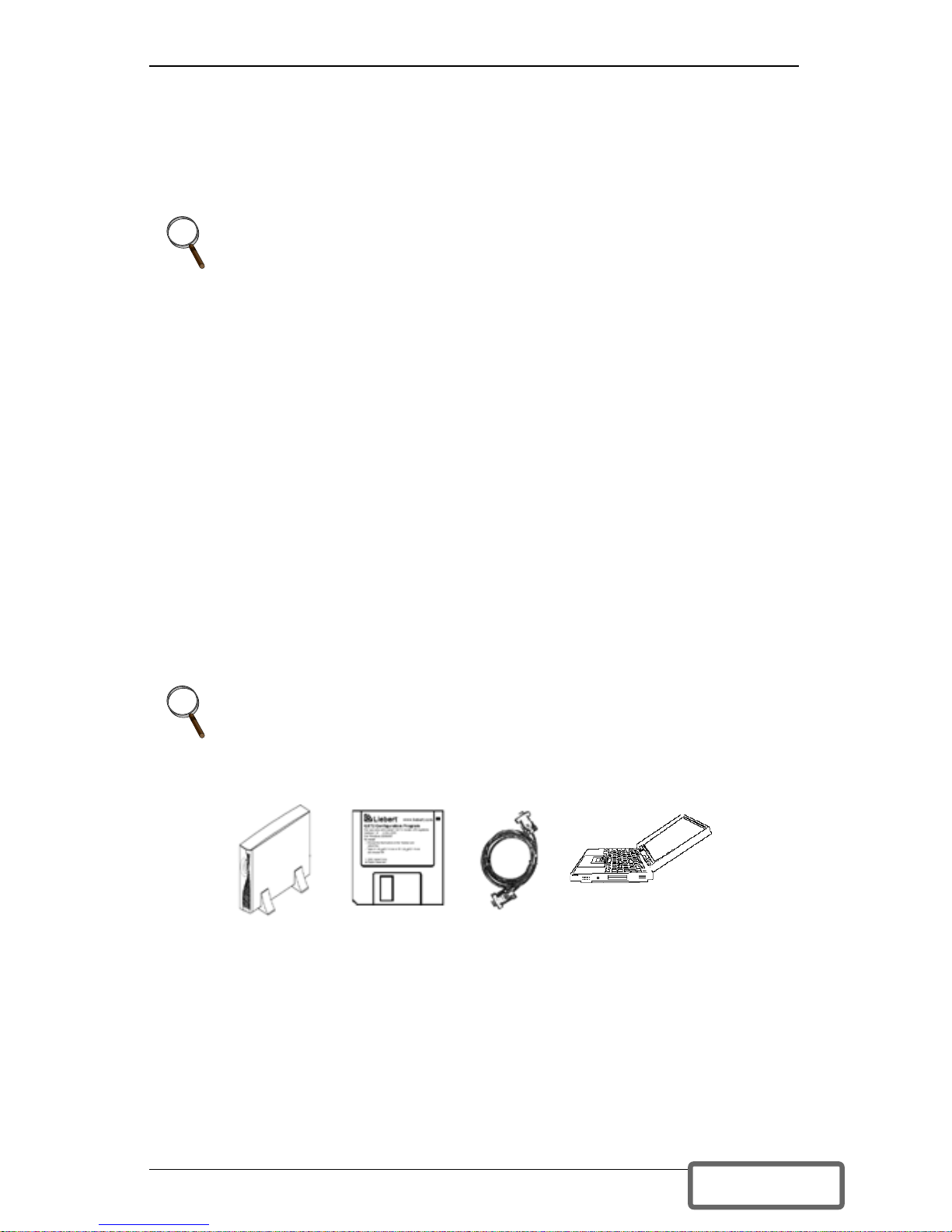
In addition to the Liebert GXT2U UPS, you will need the configuration program
diskette and serial cable (beige or tan, 3-wire: GND, TX, RX; straight through 2-
2, 3-3, 5-5) included in the UPS accessory box. The BLACK ML9P9S CONTACT
CLOSURE communication cable IS NOT compatible with the configuration
program. A Windows 95
®
, 98®, or NT® computer—desktop or laptop—is also
required to set up and run the configuration program.
NOTE
The UPS must be turned off—and not powering connected equipment—
before you make any changes to configuration settings.
While the UPS is in Normal Mode operation, press the OFF button
once to put the UPS into Bypass Mode.
Once the UPS is in Bypass Mode operation, press and release the OFF
button two distinct times (for about a second each time) to turn off the
UPS.
NOTE
This program is compatible with UPS models beginning with
“GXT2-”, as in “GXT2-2700RT208.” It is not compatible with earlier
versions of the Liebert GXT UPS.
DISCONTINUED
PRO DU C T
Page 27
23
MAINTENANCE
The Liebert GXT2U requires very little maintenance. The batteries are valveregulated, nonspillable, lead acid and should be kept charged to obtain their
designed life. The UPS continuously charges the batteries when connected to
the utility supply.
When storing the UPS for any length of time, it is recommended to plug the
UPS in for at least 24 hours every four to six months to ensure full recharge of
the batteries.
The Liebert GXT2U is designed to allow the user to safely replace the internal
batteries. Read the safety cautions before proceeding. Contact your local
dealer or Liebert representative to obtain the appropriate replacement battery
kit part number and pricing.
Battery Replacement
!
CAUTION
A battery can present a risk of electrical shock and high short
circuit current. The following precautions should be observed before
replacing the batteries:
• Remove rings, watches, or other metal objects.
• Use a Phillips (crosshead) screwdriver with insulated grips.
• Do not lay tools or other metal objects on top of the batteries.
• If the battery replacement kit is damaged in any way or shows
signs of leakage, contact your local dealer or Liebert representative immediately.
• Do not dispose of batteries in a fire. The batteries may explode.
DISCONTINUED
PRO DU C T
Page 28

24
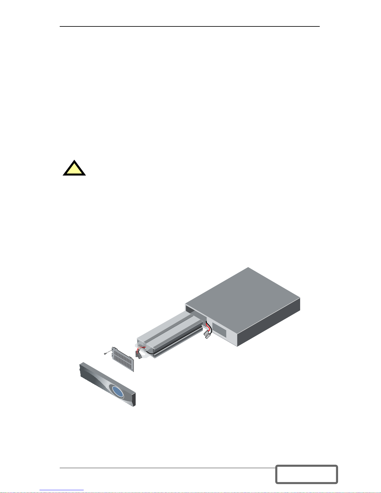
Internal Battery Replacement Procedures
1. Gently remove the front plastic bezel cover from the UPS.
2. Loosen and remove the four screws on the front battery door. Lay the bat-
tery door aside for reassembly.
3. Gently pull battery wiring out and disconnect the two slotted battery con-
nectors.
4. Grasp the battery pack assembly, and pull it out of the front of the UPS.
5. Unpack the new battery assembly taking care not to destroy the packing.
Compare new and old battery assemblies to make sure they are the same. If
so, proceed with Step 6; otherwise STOP and contact your local dealer, Liebert representative, or the Liebert Worldwide Support Group.
6. Line up and slide in the new replacement battery pack.
7. Reconnect the two slotted battery connectors and gently push the battery
wiring and battery pack assembly back into the UPS.
8. Reattach the front battery door with the four screws.
9. Reattach the front plastic bezel cover to the UPS.
NOTE
These are hot-swappable replacement batteries. However, caution
should be exercised because during this procedure the load is
unprotected from disturbances and power outages.
DISCONTINUED
PRO DU C T
Page 29
25
TROUBLESHOOTING
The information below indicates various symptoms a user may encounter in
the event the Liebert GXT2U develops a problem. Use this information to
determine whether external factors caused the problem and how to remedy
the situation.
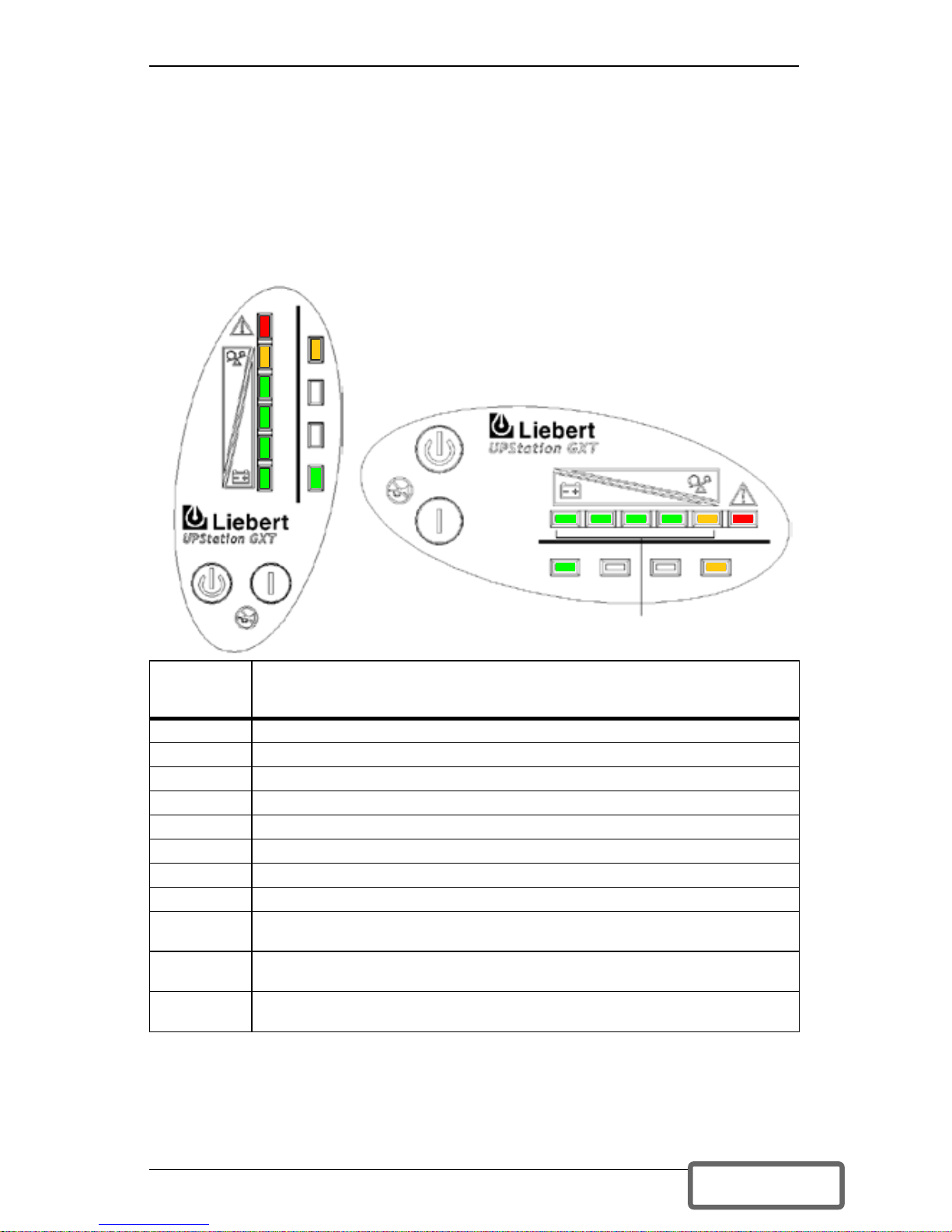
1. The Fault indicator will illuminate, indicating the UPS detected a problem.
2. An alarm will sound, alerting that the UPS requires attention.
3. One or more additional load/battery level LED indicators will be illumi-
nated to provide a diagnostic aid to the operator, as described below:
Under fault conditions, the Fault indicators will be illuminated indefinitely
while battery charger is operational, or for a maximum of 5 minutes while
battery charger is not operational.
If a problem persists, consult your local dealer, Liebert representative or
contact the Liebert Worldwide Support Group. Please have the UPS model
number and serial number available at the time of your inquiry.
LED
Status
Diagnosis/Audible alarm
All LEDs On bypass due to output overload; beep every half-second
A LED On bypass due to overtemperature condition; beep every 4 sec.
B LED On bypass due to DC bus overvoltage; beep every 4 sec.
C LED On bypass due to control power supply failure; beep every 4 sec.
D LED On bypass due to PFC failure; beep every 4 sec.
E LED On bypass due to inverter failure; beep every 4 sec.
A&C LEDs UPS failed battery test; long beep every minute
C&E LEDs UPS shutdown due to command from communication port (SNMP); no beep
Battery LED
Flashing
Internal Battery source not available (continuous horn). Check battery
connection, completely power down and reboot UPS.
AC LED
Flashing
Line-to-neutral reversal in the AC input power supply or a loss of proper
grounding; continuous horn and UPS will not start.
Bypass LED
Flashing
Utility power voltage or frequency is out of tolerance; bypass is unavailable.
This example shows the UPS
on bypass due to output overload.
Fault
E
D
C
B
A
A B C D E Fault
AC INPUT BATTERY UPS ON BYPASS
BATTERY
UPS ON
BYPASS
AC
INPUT
LOAD/BATTERY
LEVEL INDICATORS
DISCONTINUED
PRO DU C T
Page 30

26
Troubleshooting Guide
Problem Cause Solution
UPS fails to start
when the ON button
is pressed.
UPS is short circuited or overloaded.
Ensure UPS is OFF. Disconnect
all loads and ensure nothing is
lodged in output receptacles.
Ensure loads are not defective
or shorted internally.
Battery indicator
LED is illuminated.
UPS not plugged in.
UPS is operating from battery
mode, make certain UPS is
securely plugged into the wall
receptacle.
UPS input protection fuse has
blown/opened.
UPS is operating from battery
mode. Save data and close
applications. Replace UPS
input fuse, then restart UPS.
Utility voltage out of UPS input
range.
UPS is operating from battery
mode. Save data and close
applications. Ensure utility supply voltage is within acceptable
limits for UPS.
UPS has reduced
battery time.
Batteries are not fully charged.
Keep UPS plugged in continuously at least 24 hours to
recharge batteries.
UPS is overloaded.
Check load level display and
reduce the load on the UPS.
Batteries may not be able to
hold a full charge due to age.
Replace batteries. Contact your
local dealer, Liebert representative or the Liebert Worldwide
Support Group for replacement
battery kit.
Fault and Bypass
indicator LEDs and
all load level LEDs
are illuminated.
UPS overloaded or load equipment is faulty.
Check load level display and
remove non-essential loads.
Recalculate the load and
reduce number of loads connected to UPS. Check load
equipment for faults.
Fault and Bypass
indicator LEDs and
diagnostic LED A are
illuminated.
UPS internal fan has a problem
or UPS shutdown due to temperature condition. Load is on
bypass power.
Ensure UPS is not overloaded,
ventilation openings not
blocked, or room ambient temperature is not excessive. Wait
30 minutes to allow UPS to
cool, then restart UPS. If UPS
does not restart, contact your
local dealer, Liebert representative or the Liebert Worldwide
Support Group.
Fault and Bypass
indicator LEDs and
diagnostic LED B are
illuminated.
UPS internal DC bus overvoltage.
UPS requires service. Contact
your local dealer, Liebert representative or the Liebert Worldwide Support Group.
Fault and Bypass
indicator LEDs and
diagnostic LED C
are illuminated.
UPS control power supply fault.
UPS requires service. Contact
your local dealer, Liebert representative or the Liebert Worldwide Support Group.
DISCONTINUED
PRO DU C T
Page 31

27
Fault and Bypass
indicator LEDs and
diagnostic LED D
are illuminated.
UPS PFC (Power Factor Correction Circuit) fault.
UPS requires service. Contact
your local dealer, Liebert representative or the Liebert Worldwide Support Group.
Fault and Bypass
indicator LEDs and
diagnostic LED E are
illuminated.
UPS inverter fault.
UPS requires service. Contact
your local dealer, Liebert Representative or the Liebert
Worldwide Support Group.
Fault indicator LED
and diagnostic
LED A and C are illuminated.
UPS failed the battery test.
Replace batteries. Contact your
local dealer, Liebert representative or the Liebert Worldwide
Support Group.
Fault and Bypass
indicator LEDs and
diagnostic LED C
and E are illuminated.
UPS shutdown due to a command from the communications port(s).
Your UPS has received a signal
or command from the attached
computer. If this was inadvertent, ensure the communication
cable used is correct for your
system. For assistance, contact your local dealer, Liebert
representative or the Liebert
Worldwide Support Group.
AC LED is
flashing.
UPS detected a line-to-neutral
reversal or a loss of proper
grounding; continuous horn and
UPS will not start.This is active
only when power is first applied
to the input. Once the UPS is
running, the AC LED will not
start flashing, even if the input
wiring is changed.
Contact a qualified electrician to
verify site wiring.
Battery LED is
flashing.
Battery source is not available;
continuous horn.
Check battery connections,
completely power down and
restart UPS.
NOTE: If the battery circuit
opens while the UPS is running,
it will be detected when the next
battery test is performed.
Bypass LED is
flashing.
Bypass voltage is present, but
is disabled for use because the
voltage or frequency is outside
acceptable limits.
The AC input powers the PFC
input and serves as the bypass
source. If the AC is present but
the voltage or frequency
exceeds the acceptable range
for safe operation with a load,
the bypass will be disabled and
this LED will flash, indicating
that the bypass is unavailable.
Troubleshooting Guide (Continued)
Problem Cause Solution
DISCONTINUED
PRO DU C T
Page 32
28
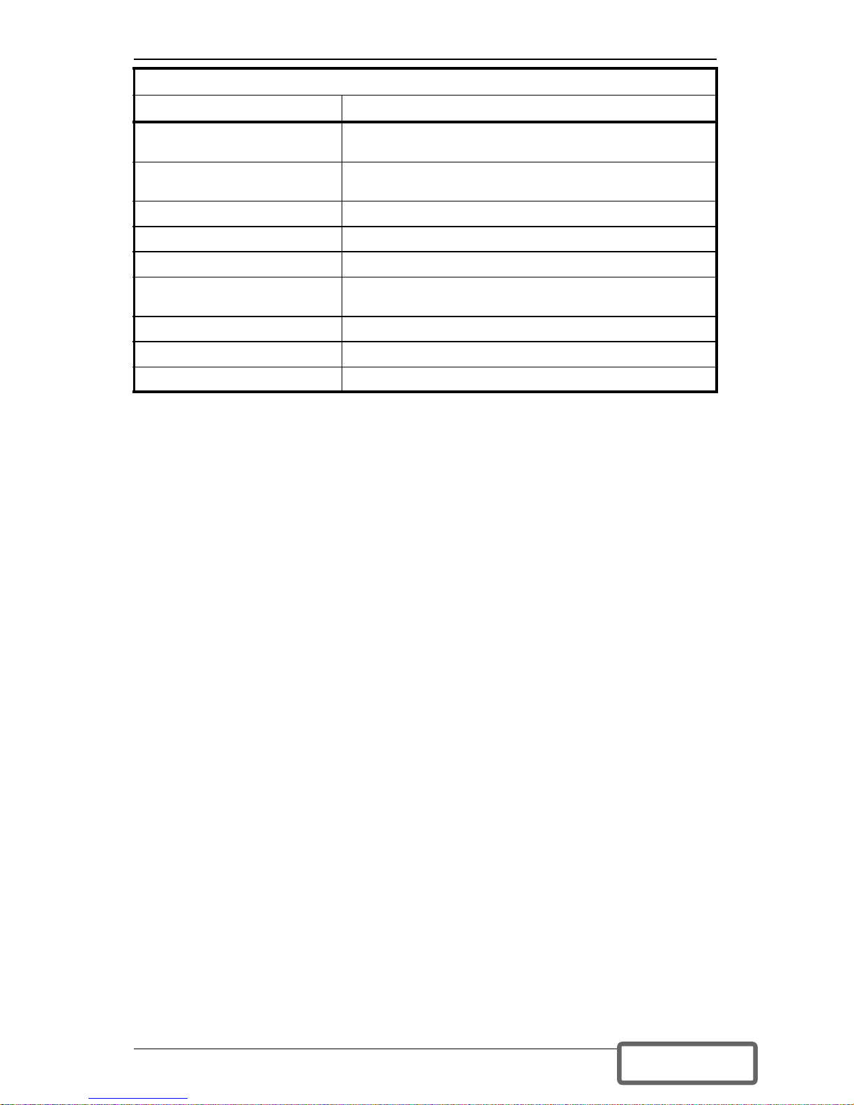
Alarm Conditions
Condition Alarm
Battery Mode (utility failure)
One short beep every 10 seconds; more than 2 minutes
of run time remaining
Low Battery
Two short beeps every 5 seconds; less than 2 minutes
of run time remaining
Output Overload (bypass) One short beep every half second
Overtemperature (bypass) A one-second beep every 4 seconds
DC Bus Overvoltage (bypass) A one-second beep every 4 seconds
Control Power Supply
Failure (bypass)
A one-second beep every 4 seconds
PFC Failure (bypass) A one-second beep every 4 seconds
Inverter Failure A one-second beep every 4 seconds
Battery Test Failure A 2-second beep every minute
DISCONTINUED
PRO DU C T
Page 33

29
SPECIFICATIONS
Model Number GXT2-2700RT208
Model Rating 2700VA/1890W
DIMENSIONS: in. (mm)
Unit - W x D x H: in. (mm) 3.5 x 24.2 x 17 (87 x 618 x 430)
Shipping - W x D x H: in. (mm) 10.5 x 27.2 x 23 (268 x 692 x 585)
WEIGHT lbs (kg)
Unit: lbs (kg) 75.2 (34.1)
Shipping: lbs (kg) 84.9 (38.5)
INPUT AC PARAMETERS
Voltage Range (typical) 208 VAC nominal; variable based on output load
100% - 90% loading 176 VAC/ 280 VAC
90% - 70% loading 159 VAC/ 280 VAC
70% - 30% loading 139 VAC/ 280 VAC
30% - 0% loading 119 VAC/ 280 VAC
Frequency 40 - 70 Hz; Auto Sensing
Input Power Cord 10 ft. attached w/ NEMA L6-20 plug
OUTPUT AC PARAMETERS
Output Receptacles
(2) NEMA L6-15R
(1) NEMA L6-20R
Voltage 200/208 /220/230 / 240 (user configurable) VAC; ±3%
Frequency 50 Hz or 60 Hz
Waveform Sinewave
Main Mode Overload
200% for 8 cycles; 130% for 10 seconds with transfer to
bypass
BATTERY PARAMETERS
Type Valve-regulated, nonspillable, lead acid
Qty x V x Rating 6 x 12V x 9.0 AH
Battery Mfg/Part #
Panasonic/ UP-VW1245P1
Yuasa/ REW 45-12
Back-Up Time See Battery Run Times charts
Recharge Time
5 Hours to 95% capacity after full discharge into 100% load
(Internal Batteries Only)
ENVIRONMENTAL
Operating Temp +32°F to +104°F (0°C to +40°C)
Storage Temp +5°F to +122°F (-15°C to +50°C)
Relative Humidity 0% to 95%, non-condensing
Operating Elevation Up to 10,000 ft. (3000 m) at 104°F (40°C) without derating
Storage Elevation 50,000 ft. (15,000 m) maximum
Audible Noise
<55 dBA, at 1 meter from the rear
<50 dBA, at 1 meter from the front or sides
AGENCY
Safety UL 1778, c-UL Listed
RFI/EMI FCC Part 15, Subpart B, Class A
Surge Immunity IEEE 587 Category A & B
Transportation ISTA Procedure 1A
DISCONTINUED
PRO DU C T
Page 34

30
Battery Cabinet Specifications
Model Number GXT2-72VBATT
Used w/ UPS Model GXT2-2700RT208
DIMENSIONS in (mm)
Unit - W x D x H in. (mm) 3.5 x 24.2 x 17 (87 x 618 x 430)
Shipping - W x D x H in. (mm) 10.5 x 27.2 x 23 (268 x 692 x 585)
WEIGHT, lb (kg)
Unit: lbs (kg) 93.6 (42.5)
Shipping: lbs (kg) 102.5 (46.5)
BATTERY PARAMETERS
Type Valve-regulated, nonspillable, lead acid
Qty x V x Rating 2 x 6 x 12V x 9.0 AH
Battery Mfg/Part #
Panasonic/UP-VW1245P1
Yuasa/REW 45-12
Back-Up Time See Battery Run Times charts
ENVIRONMENTAL
Operating Temp +32°F to +104°F (0°C to +40°C)
Storage Temp +5°F to +122°F (-15°C to +50°C)
Relative Humidity 0% to 95%, non-condensing
Operating Elevation
Up to 10,000 ft. (3000 m) at 104°F (40°C)
without derating
Storage Elevation 50,000 ft. (15,000 m) maximum
AGENCY
Safety UL 1778, c-UL Listed
RFI/EMI FCC Part 15, Subpart B, Class A
Transportation ISTA Procedure 1A
DISCONTINUED
PRO DU C T
Page 35
31
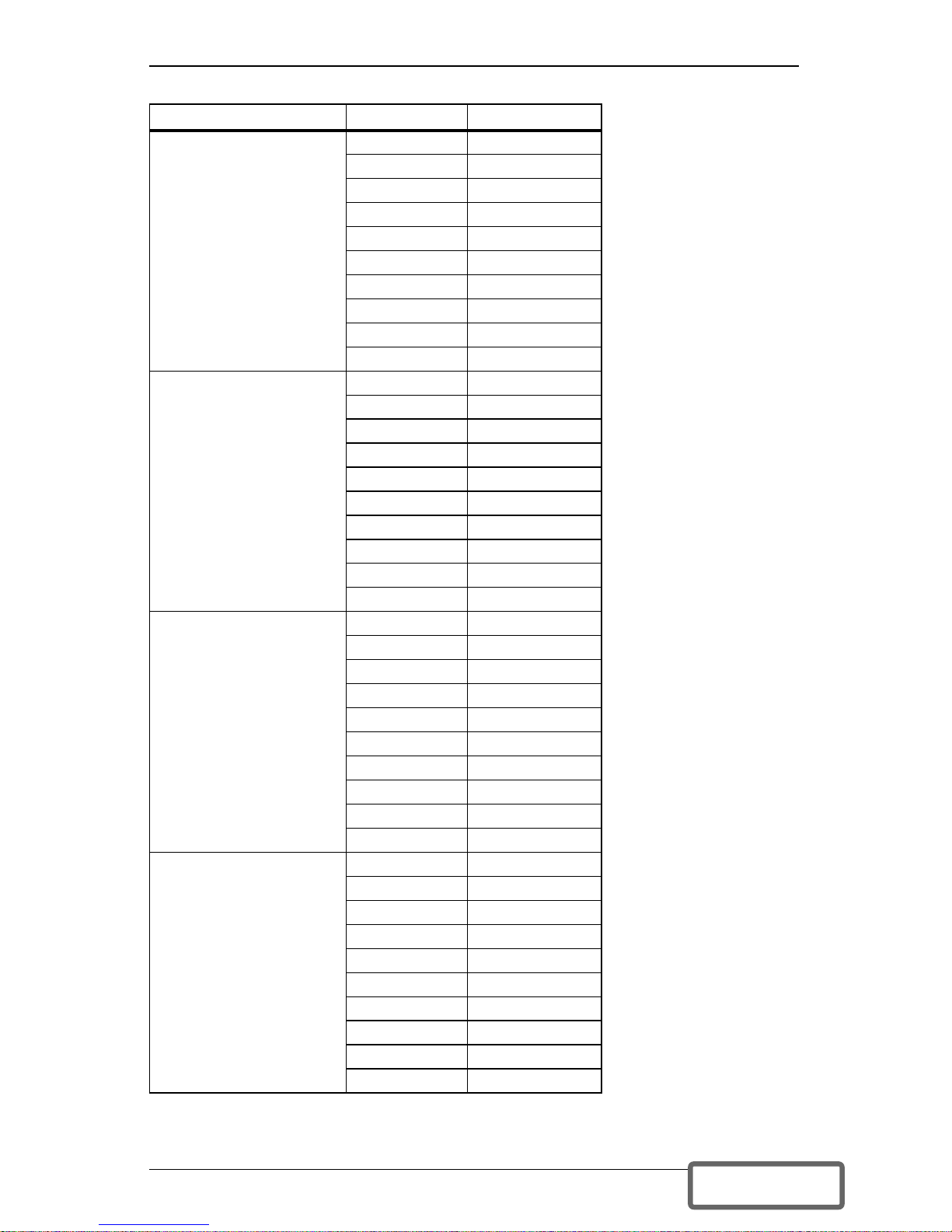
Battery Run Times
Load % Estimated Time
Internal Battery
(minutes)
10% 91
20% 46
30% 30
40% 21
50% 16
60% 11
70% 9
80% 8
90% 7
100% 5
Internal Battery
+ 1 External Battery
Cabinet (minutes)
10% 364
20% 184
30% 120
40% 84
50% 64
60% 44
70% 36
80% 32
90% 28
100% 20
Internal Battery
+ 2 External Battery
Cabinets (minutes)
10% 728
20% 368
30% 240
40% 168
50% 128
60% 88
70% 72
80% 64
90% 56
100% 40
Internal Battery
+ 3 External Battery
Cabinets (minutes)
10% 1092
20% 552
30% 360
40% 252
50% 192
60% 132
70% 108
80% 96
90% 84
100% 60
DISCONTINUED
PRO DU C T
Page 36
32
Product Warranty Registration
To register for warranty protection:
• Visit the Quick Links section of our Web site at:
http://www.liebert.com
• Click on Product Warranty Registration and fill in the form.
If you have any questions, please contact us at:
US: 800-222-5877
Outside the US: 614-841-6755
Internal Battery
+ 4 External Battery
Cabinets (minutes)
10% 1456
20% 736
30% 480
40% 336
50% 256
60% 176
70% 144
80% 128
90% 112
100% 80
Note: Approximate discharge times are in minutes and at 77°F
(25°C) with a 100% resistive load.
Battery Run Times (Continued)
Load % Estimated Time
DISCONTINUED
PRO DU C T
Page 37

33
DISCONTINUED
PRO DU C T
Page 38

34
DISCONTINUED
PRO DU C T
Page 39

DISCONTINUED
PRO DU C T
Page 40
Ensuring The High Availability
0f Mission-Critical Data And Applications.
While every precaution has been taken to ensure the accuracy and completeness of this literature, Liebert Corporation assumes
no responsibility and disclaims all liability for damages resulting from use of this information or for any errors or omissions.
© 2007 Liebert Corporation
All rights reserved throughout the world.
Specifications subject to change without notice.
® Liebert is the registered trademark of Liebert Corporation. All names referred to are trademarks or
registered trademarks of their respective owners.
Locations
United States
1050 Dearborn Drive
P.O. Box 29186
Columbus, OH 43229
Europe
Via Leonardo Da Vinci 8
Zona Industriale Tognana
35028 Piove Di Sacco (PD) Italy
+39 049 9719 111
Fax: +39 049 5841 257
Asia
7/F, Dah Sing Financial Centre
108 Gloucester Road, Wanchai
Hong Kong
852 2572220
Fax: 852 28029250
The global leader in enabling Business-Critical Continuity™.
Business-Critical Continuity, Emerson Network Power and the Emerson Network Power logo are
trademarks and service marks of Emerson Electric Co.
©2007 Emerson Electric Co.
AC Power Systems
Connectivity
DC Power Systems
Integrated Cabinet Solutions
Embedded Computing
Embedded Power
Power Switching & Control
Precision Cooling
Outside Plant
EmersonNetworkPower.com
Services
Site Monitoring
Surge Protection
Technical Support / Service
Web Site
www.liebert.com
Monitoring
800-222-5877
[email protected]
Outside the US: 614-841-6755
Single-Phase UPS
800-222-5877
[email protected]
Outside the US: 614-841-6755
Three-Phase UPS
800-543-2378
[email protected]
Environmental Systems
800-543-2778
Outside the United States
614-888-0246
Emerson Network Power.
SL-23154_REV02_01-08
DISCONTINUED
PRO DU C T
 Loading...