

Page 1

Liebert® EXM™BDC
User Manual—10-100kVA, 60Hz
Page 2

Page 3

TABLE OF CONTENTS
IMPORTANT SAFETY INSTRUCTIONS . . . . . . . . . . . . . . . . . . . . . . . . . . . . . . . . . . . . . . . . . . . . . . . .1
SAVE THESE INSTRUCTIONS . . . . . . . . . . . . . . . . . . . . . . . . . . . . . . . . . . . . . . . . . . . . . . . . . . . . . . . .1
GLOSSARY OF SYMBOLS . . . . . . . . . . . . . . . . . . . . . . . . . . . . . . . . . . . . . . . . . . . . . . . . . . . . . . . . . . . 5
1.0 LIEBERT EXM BDC . . . . . . . . . . . . . . . . . . . . . . . . . . . . . . . . . . . . . . . . . . . . . . . . . . . . . . . . . . . 6
1.1 Normal (UPS) Mode. . . . . . . . . . . . . . . . . . . . . . . . . . . . . . . . . . . . . . . . . . . . . . . . . . . . . . . . . . . . . . . . . . . . . . . . . . . . . . 6
1.2 Maintenance Mode. . . . . . . . . . . . . . . . . . . . . . . . . . . . . . . . . . . . . . . . . . . . . . . . . . . . . . . . . . . . . . . . . . . . . . . . . . . . . . . 6
1.3 Locating the Cabinet. . . . . . . . . . . . . . . . . . . . . . . . . . . . . . . . . . . . . . . . . . . . . . . . . . . . . . . . . . . . . . . . . . . . . . . . . . . . . .7
1.4 Cable Installation . . . . . . . . . . . . . . . . . . . . . . . . . . . . . . . . . . . . . . . . . . . . . . . . . . . . . . . . . . . . . . . . . . . . . . . . . . . . . . . . .7
1.4.1 Wiring Preparation . . . . . . . . . . . . . . . . . . . . . . . . . . . . . . . . . . . . . . . . . . . . . . . . . . . . . . . . . . . . . . . . . . . . . . . . . . . . . . . . .7
1.4.2 Power Cable Installation. . . . . . . . . . . . . . . . . . . . . . . . . . . . . . . . . . . . . . . . . . . . . . . . . . . . . . . . . . . . . . . . . . . . . . . . . . . .7
1.4.3 Input/Output Wiring . . . . . . . . . . . . . . . . . . . . . . . . . . . . . . . . . . . . . . . . . . . . . . . . . . . . . . . . . . . . . . . . . . . . . . . . . . . . . . 8
1.4.4 Accessory Fuses and Back-Feed Breaker Wiring . . . . . . . . . . . . . . . . . . . . . . . . . . . . . . . . . . . . . . . . . . . . . . . . . . . 9
1.5 Bolting Cabinets Together. . . . . . . . . . . . . . . . . . . . . . . . . . . . . . . . . . . . . . . . . . . . . . . . . . . . . . . . . . . . . . . . . . . . . . . . 15
1.5.1 Floor Installation . . . . . . . . . . . . . . . . . . . . . . . . . . . . . . . . . . . . . . . . . . . . . . . . . . . . . . . . . . . . . . . . . . . . . . . . . . . . . . . . . .16
1.5.2 Cable Entry. . . . . . . . . . . . . . . . . . . . . . . . . . . . . . . . . . . . . . . . . . . . . . . . . . . . . . . . . . . . . . . . . . . . . . . . . . . . . . . . . . . . . . .16
1.5.3 Optional Cabinets. . . . . . . . . . . . . . . . . . . . . . . . . . . . . . . . . . . . . . . . . . . . . . . . . . . . . . . . . . . . . . . . . . . . . . . . . . . . . . . . .16
1.6 Liebert EXM UPS Bypass Assembly. . . . . . . . . . . . . . . . . . . . . . . . . . . . . . . . . . . . . . . . . . . . . . . . . . . . . . . . . . . . . . . 17
1.6.1 Liebert EXM BDC Interface . . . . . . . . . . . . . . . . . . . . . . . . . . . . . . . . . . . . . . . . . . . . . . . . . . . . . . . . . . . . . . . . . . . . . . . . 17
2.0 INSTALLATION DRAWINGS . . . . . . . . . . . . . . . . . . . . . . . . . . . . . . . . . . . . . . . . . . . . . . . . . . 20
3.0 SPECIFICATIONS . . . . . . . . . . . . . . . . . . . . . . . . . . . . . . . . . . . . . . . . . . . . . . . . . . . . . . . . . . . . 34
3.1 Electrical Characteristics . . . . . . . . . . . . . . . . . . . . . . . . . . . . . . . . . . . . . . . . . . . . . . . . . . . . . . . . . . . . . . . . . . . . . . . . 36
3.2 Torque Requirements . . . . . . . . . . . . . . . . . . . . . . . . . . . . . . . . . . . . . . . . . . . . . . . . . . . . . . . . . . . . . . . . . . . . . . . . . . . 38
FIGURES
Figure 1 Single input UPS with external Liebert EXM BDC with optional internal transformer—Typical
configuration . . . . . . . . . . . . . . . . . . . . . . . . . . . . . . . . . . . . . . . . . . . . . . . . . . . . . . . . . . . . . . . . . . . . . . . . . . . . . . . . 6
Figure 2 Liebert EXM BDC—Access plate removed. . . . . . . . . . . . . . . . . . . . . . . . . . . . . . . . . . . . . . . . . . . . . . . . . . . . . .7
Figure 3 Accessory fuses . . . . . . . . . . . . . . . . . . . . . . . . . . . . . . . . . . . . . . . . . . . . . . . . . . . . . . . . . . . . . . . . . . . . . . . . . . . . . 9
Figure 4 Liebert EXM BDC with distribution, single input . . . . . . . . . . . . . . . . . . . . . . . . . . . . . . . . . . . . . . . . . . . . . . .10
Figure 5 Liebert EXM BDC wiring, without transformer option, single input . . . . . . . . . . . . . . . . . . . . . . . . . . . . . . 11
Figure 6 Liebert EXM BDC wiring with transformer option, single input . . . . . . . . . . . . . . . . . . . . . . . . . . . . . . . . .12
Figure 7 Wiring for LDMF with panelboard . . . . . . . . . . . . . . . . . . . . . . . . . . . . . . . . . . . . . . . . . . . . . . . . . . . . . . . . . . . . .13
Figure 8 Wiring for LDMF with subfeed breakers . . . . . . . . . . . . . . . . . . . . . . . . . . . . . . . . . . . . . . . . . . . . . . . . . . . . . . .14
Figure 9 Bolting Liebert EXM UPS to a Liebert EXM BDC . . . . . . . . . . . . . . . . . . . . . . . . . . . . . . . . . . . . . . . . . . . . . . . 15
Figure 10 Cabinet arrangement. . . . . . . . . . . . . . . . . . . . . . . . . . . . . . . . . . . . . . . . . . . . . . . . . . . . . . . . . . . . . . . . . . . . . . . . . 17
Figure 11 Liebert EXM UPS bypass assembly connections. . . . . . . . . . . . . . . . . . . . . . . . . . . . . . . . . . . . . . . . . . . . . . . 17
Figure 12 Input dry contacts—J26. . . . . . . . . . . . . . . . . . . . . . . . . . . . . . . . . . . . . . . . . . . . . . . . . . . . . . . . . . . . . . . . . . . . . .18
Figure 13 Output dry contacts and EPO wiring . . . . . . . . . . . . . . . . . . . . . . . . . . . . . . . . . . . . . . . . . . . . . . . . . . . . . . . . . .18
Figure 14 Liebert EXM BDC with 225A or 400A panelboards—Main components. . . . . . . . . . . . . . . . . . . . . . . . 20
Figure 15 Liebert EXM BDC with two subfeed breakers—Main components . . . . . . . . . . . . . . . . . . . . . . . . . . . . . .21
Figure 16 Liebert EXM BDC with optional SKRU and transformer . . . . . . . . . . . . . . . . . . . . . . . . . . . . . . . . . . . . . . . 22
Figure 17 Busbars—Liebert EXM BDC with panelboard . . . . . . . . . . . . . . . . . . . . . . . . . . . . . . . . . . . . . . . . . . . . . . . . . 23
Vertiv |Liebert® BDC User Manual | Rev. 3 | 01/18 | i
Page 4

Figure 18 Busbars—Liebert EXM BDC . . . . . . . . . . . . . . . . . . . . . . . . . . . . . . . . . . . . . . . . . . . . . . . . . . . . . . . . . . . . . . . . . 24
Figure 19 Lineup arrangement, Liebert EXM with Liebert EXM BDC . . . . . . . . . . . . . . . . . . . . . . . . . . . . . . . . . . . . . 25
Figure 20 Outline drawing, Liebert EXM BDC for Liebert EXM, 10-100kVA. . . . . . . . . . . . . . . . . . . . . . . . . . . . . . . 26
Figure 21 Liebert EXM BDC transformer location. . . . . . . . . . . . . . . . . . . . . . . . . . . . . . . . . . . . . . . . . . . . . . . . . . . . . . . 27
Figure 22 One-line diagram, 208V single input 10-100kVA UPS with three-breaker Liebert EXM BDC
and panelboard . . . . . . . . . . . . . . . . . . . . . . . . . . . . . . . . . . . . . . . . . . . . . . . . . . . . . . . . . . . . . . . . . . . . . . . . . . . . . 28
Figure 23 One-line diagram, 208V single input 10-100kVA UPS with three-breaker Liebert EXM BDC,
input isolation transformer and panelboard . . . . . . . . . . . . . . . . . . . . . . . . . . . . . . . . . . . . . . . . . . . . . . . . . . 29
Figure 24 One-line diagram, 208V single input 10-100kVA UPS with three-breaker Liebert EXM BDC
and two subfeed breakers . . . . . . . . . . . . . . . . . . . . . . . . . . . . . . . . . . . . . . . . . . . . . . . . . . . . . . . . . . . . . . . . . . . 30
Figure 25 One-line diagram, 208V single input 60-100kVA UPS with three-breaker Liebert EXM BDC,
input isolation transformer and two subfeed breakers . . . . . . . . . . . . . . . . . . . . . . . . . . . . . . . . . . . . . . . . .31
Figure 26 One-line diagram, 208V dual input 10-100kVA UPS with three-breaker Liebert EXM BDC
and panelboard . . . . . . . . . . . . . . . . . . . . . . . . . . . . . . . . . . . . . . . . . . . . . . . . . . . . . . . . . . . . . . . . . . . . . . . . . . . . . 32
Figure 27 One-line diagram, 208V dual input 10-100kVA UPS with three-breaker Liebert EXM BDC
and two subfeed breakers . . . . . . . . . . . . . . . . . . . . . . . . . . . . . . . . . . . . . . . . . . . . . . . . . . . . . . . . . . . . . . . . . . . 33
TABLES
Table 1 Control wiring for Liebert EXM to Liebert EXM BDC . . . . . . . . . . . . . . . . . . . . . . . . . . . . . . . . . . . . . . . . . . . .8
Table 2 Liebert EXM BDC interface . . . . . . . . . . . . . . . . . . . . . . . . . . . . . . . . . . . . . . . . . . . . . . . . . . . . . . . . . . . . . . . . . . .17
Table 3 Output dry contact relays . . . . . . . . . . . . . . . . . . . . . . . . . . . . . . . . . . . . . . . . . . . . . . . . . . . . . . . . . . . . . . . . . . . .19
Table 4 Wiring for Liebert EXM to Liebert EXM BDC . . . . . . . . . . . . . . . . . . . . . . . . . . . . . . . . . . . . . . . . . . . . . . . . . . 27
Table 5 Hardware torque values . . . . . . . . . . . . . . . . . . . . . . . . . . . . . . . . . . . . . . . . . . . . . . . . . . . . . . . . . . . . . . . . . . . . . 27
Table 6 Physical standards and parameters . . . . . . . . . . . . . . . . . . . . . . . . . . . . . . . . . . . . . . . . . . . . . . . . . . . . . . . . . . 34
Table 7 Mechanical characteristics, Liebert EXM BDC, 10-100kVA . . . . . . . . . . . . . . . . . . . . . . . . . . . . . . . . . . . . 34
Table 8 Liebert EXM BDC, 60-100kVA, mechanical characteristics . . . . . . . . . . . . . . . . . . . . . . . . . . . . . . . . . . . . 35
Table 9 Liebert EXM BDC heat dissipation . . . . . . . . . . . . . . . . . . . . . . . . . . . . . . . . . . . . . . . . . . . . . . . . . . . . . . . . . . . 35
Table 10 Liebert EXM BDC input currents, single input, main, without transformer . . . . . . . . . . . . . . . . . . . . . . 36
Table 11 Liebert EXM BDC input currents, dual input, rectifier, without transformer. . . . . . . . . . . . . . . . . . . . . 36
Table 12 Liebert EXM BDC output currents . . . . . . . . . . . . . . . . . . . . . . . . . . . . . . . . . . . . . . . . . . . . . . . . . . . . . . . . . . . 37
Table 13 Liebert EXM BDC input currents, dual input, bypass, without transformer . . . . . . . . . . . . . . . . . . . . . 37
Table 14 Busbar torque for power wiring . . . . . . . . . . . . . . . . . . . . . . . . . . . . . . . . . . . . . . . . . . . . . . . . . . . . . . . . . . . . . . 38
Table 15 Terminal block torque with compression lugs for control wiring . . . . . . . . . . . . . . . . . . . . . . . . . . . . . . . 38
Table 16 Recommended lug sizes (compression type) M12, 1/2" bolt. . . . . . . . . . . . . . . . . . . . . . . . . . . . . . . . . . . . 38
Table 17 Electrical data—Liebert EXM BDC, 480VAC input, 208VAC output, single input, with
480V:208V transformer . . . . . . . . . . . . . . . . . . . . . . . . . . . . . . . . . . . . . . . . . . . . . . . . . . . . . . . . . . . . . . . . . . . . . 39
Table 18 Electrical data—Liebert EXM BDC, 600VAC input, 208VAC output, single input, with
600V:208V transformer . . . . . . . . . . . . . . . . . . . . . . . . . . . . . . . . . . . . . . . . . . . . . . . . . . . . . . . . . . . . . . . . . . . . . 39
Table 19 Electrical data—Liebert EXM BDC, 208VAC or 220VAC input, single input, with
208V:208V or 220V:220V transformer . . . . . . . . . . . . . . . . . . . . . . . . . . . . . . . . . . . . . . . . . . . . . . . . . . . . . . . 39
Table 20 Breaker torque . . . . . . . . . . . . . . . . . . . . . . . . . . . . . . . . . . . . . . . . . . . . . . . . . . . . . . . . . . . . . . . . . . . . . . . . . . . . . . 39
Vertiv |Liebert® EXM™ BDC User Manual | Rev. 3 | 01/18 | ii
Page 5

IMPORTANT SAFETY INSTRUCTIONS
SAVE THESE INSTRUCTIONS
This manual contains important instructions that should be followed during installation of the Liebert EXM BDC
(bypass distribution cabinet).
Read this manual thoroughly, paying special attention to the sections that apply to your installation, before
working with the UPS. Retain this manual for use by installing personnel.
A properly trained and qualified electrical contractor should oversee the installation of the equipment.
The Liebert EXM BDC cannot be put into operation until it is commissioned by the manufacturer or authorized
engineer. Otherwise, human safety may be endangered and damage to the UPS will not be covered by the
warranty.
The Liebert EXM BDC is designed for commercial and industrial uses and cannot be used as life support
equipment.
WARNING
Risk of moving heavy equipment and electric shock. Can cause equipment damage, injury and death.
Exercise extreme care when handling UPS cabinets to avoid equipment damage or injury to personnel.
The Liebert EXM BDC’s weight ranges from 660 to 1752 lb. (300 to 794kg).
Determine the unit’s weight and locate the center of gravity symbols before handling the Liebert EXM
BDC. Test lift and balance the cabinet before transporting it. Never tilt equipment more than 15
degrees from vertical.
In case of fire involving electrical equipment, use only carbon dioxide fire extinguishers or those approved
for use in fighting electrical fires.
Extreme caution is required when performing maintenance.
Be constantly aware that the UPS system contains high DC as well as AC voltages.
Check for voltage with both AC and DC voltmeters prior to making contact.
AVERTISSEMENT
Risque lors du déplacement de l'équipement lourd et de décharge électrique pouvant entraîner des
dommages matériels, des blessures et même la mort.
Faites preuve d'une extrême prudence lors de la manutention des armoires ASC afin d'éviter de les
endommager ou de blesser le personnel. Les armoires Liebert EXM BDC pèsent de 660 à 1752 lb (de 300
à 794 kg).
Déterminez le poids de l'unité et trouvez les symboles de centre de gravité avant de déplacer l'armoire
Liebert EXM BDC. Faites des essais de levage et d'équilibre avant de transporter l'armoire. N'inclinez
jamais l'équipement à plus de 15 degrés à la verticale.
En cas d'incendie associé à du matériel électrique, n'utilisez que des extincteurs à dioxyde de carbone ou
homologués pour la lutte contre les incendies d'origine électrique.
Les opérations d'entretien requièrent une extrême prudence.
Soyez toujours conscient du fait que le système ASC contient des tensions c.c. et c.a. élevées.
Vérifiez les tensions avec des voltmètres c.a. et c.c. avant d'établir tout contact.
Vertiv | Liebert® EXM™ BDC User Manual | Rev. 3 | 01/18 | 1
Page 6

WARNING
Risk of electric shock. Can cause equipment damage, injury and death.
As with other types of high power equipment, dangerous voltages are present within the UPS and battery
enclosure even after input power has been disconnected. The risk of contact with these voltages is
minimized as the live component parts are housed behind a metal panel. Further internal safety screens
make the equipment protected to IP20 standards. Never remove panels or covers or open doors that will
expose internal components to contact.
Read and follow all warnings, cautions and safety and operating instructions to avoid serious injury or
death from electric shock. No risk exists to any personnel when operating the equipment in the normal
manner, following the recommended operating procedures.
All equipment maintenance and servicing procedures involve internal access and should be carried out
only by trained personnel.
AVERTISSEMENT
Risque de décharge électrique pouvant entraîner des dommages matériels, des blessures et même la
mort.
À l'instar des autres types d'équipement haute puissance, des tensions dangereuses sont présentes à
l'intérieur de l'armoire ASC et du châssis de batteries même après le débranchement de l'alimentation
d'entrée. Le risque de contact avec ces tensions est diminué, car les parties de composants sous tension
sont abritées derrière un panneau métallique. D'autres écrans de sécurité internes protègent
l'équipement en conformité avec les normes IP20. Ne retirez jamais les panneaux ou les couvercles et
n'ouvrez pas les portes donnant accès aux composants internes avec lesquels vous pouvez entrer en
contact.
Veuillez lire et suivre l'ensemble des avertissements, des mises en garde et des instructions de sécurité et
de fonctionnement afin d'éviter des blessures graves, voire la mort, pouvant être causées par une
décharge électrique. Il n'y a aucun risque pour le personnel lorsque l'équipement est utilisé normalement,
en suivant les procédures de fonctionnement recommandées.
Toutes les procédures de réparation et d'entretien de l'équipement exigent un accès à l'intérieur de
l'armoire et devraient être menées uniquement par du personnel compétent.
Ground Leakage Currents
WARNING
Risk of electric shock from high leakage current. Can cause injury, property damage and death.
EARTH CONNECTION IS ESSENTIAL BEFORE CONNECTING THE INPUT SUPPLY.
Earth leakage current exceeds 3.5 mA and is less than 1000 mA.
Transient and steady-state earth leakage currents, which may occur when starting the equipment, should
be taken into account when selecting instantaneous RCCB or RCD devices.
Residual Current Circuit Breakers (RCCBs) must be selected sensitive to DC unidirectional pulses (Class
A) and insensitive to transient current pulses.
Note also that the earth leakage currents of the load will be carried by this RCCB or RCD.
This equipment must be earthed in accordance with the local electrical code of practice.
Vertiv | Liebert® EXM™ BDC User Manual | Rev. 3 | 01/18 | 2
Page 7

AVERTISSEMENT
Risque de décharge électrique due à un courant de fuite élevé pouvant causer des blessures, des
dommages matériels et même la mort.
IL EST PRIMORDIAL D'ASSURER UNE CONNEXION DE TERRE AVANT DE BRANCHER
L'ALIMENTATION D'ENTRÉE. La fuite à la terre est supérieure à 3,5 mA et inférieure à 1 000 mA.
Vous devez tenir compte des fuites de courant transitoires et permanentes à la terre, susceptibles de se
produire au démarrage de l'équipement, lors de la sélection des dispositifs DDFT instantanés.
Vous devez sélectionner des disjoncteurs différentiels de fuite à la terre (DDFT) sensibles aux impulsions
unidirectionnelles c.c. (classe A) et insensibles aux impulsions de courant transitoires.
Notez également que les courants de fuite à la terre de la charge seront acheminés par ce dispositif
DDFT.
Cet équipement doit être mis à la terre conformément au code national de l'électricité.
WARNING
Risk of electric shock. Can cause injury, property damage and death.
Under typical operation and with all UPS doors closed, only normal safety precautions are necessary. The
area around the UPS system should be kept free of puddles of water, excess moisture and debris.
Special safety precautions are required for procedures involving handling, installation and maintenance of
the UPS system and the internal batteries (internal batteries accommodated by the 10-40kVA frame
only). Observe all safety precautions in this manual before handling or installing the UPS system as well
as during all maintenance procedures. Observe all battery safety precautions before working on or near
the battery.
This equipment contains several circuits that are energized with high voltage. Only test equipment
designed for troubleshooting should be used. This is particularly true for oscilloscopes. Always check with
AC and DC voltmeters to ensure safety before making contact or using tools. Even when the power is
turned Off, dangerously high electric charges may exist within the UPS.
All power and control wiring should be installed by a qualified electrician. All power and control wiring
must comply with the NEC and applicable local codes.
ONLY qualified service personnel should perform maintenance on the UPS system. When performing
maintenance with any part of the equipment under power, service personnel and test equipment should
be standing on rubber mats. The service personnel should wear insulating shoes for isolation from direct
contact with the floor (earth ground).
Never work alone, even if all power is removed from the equipment. A second person should be standing
by to assist and summon help in case an accident should occur.
Vertiv | Liebert® EXM™ BDC User Manual | Rev. 3 | 01/18 | 3
Page 8

AVERTISSEMENT
Risque de décharge électrique pouvant causer des blessures, des dommages matériels et même la mort.
Les précautions de sécurité habituelles suffisent lorsque le système ASC est en mode de fonctionnement
normal et que toutes les portes sont fermées. La zone entourant le système ASC doit être exempte de
flaques d’eau, d’humidité excessive et de débris.
Des précautions de sécurité spéciales sont requises pour les procédures associées à la manutention, à
l’installation et à l’entretien du système ASC. Observez toutes les précautions de sécurité décrites dans le
présent manuel avant de manipuler ou d’installer le système ASC, ainsi que pendant toutes les
procédures d’entretien.
Cet équipement comporte plusieurs circuits à haute tension. Seuls des équipements d’essai conçus pour
le dépannage doivent être utilisés. Cette mise en garde couvre notamment les oscilloscopes. Utilisez
toujours des voltmètres c.a. et c.c. pour vérifier les tensions avant d’établir un contact ou d’utiliser des
outils. Des tensions dangereusement élevées peuvent demeurer dans le système ASC même une fois
l’alimentation coupée.
Tous les câbles d’alimentation et de contrôle doivent être installés par un électricien qualifié. Tous les
câbles d’alimentation et de contrôle doivent être conformes au Code national de l’électricité des ÉtatsUnis (NEC) et celui du Canada, ainsi qu’aux codes locaux en vigueur.
L’entretien du système ASC ne doit être confié qu’à des professionnels qualifiés.
Les responsables de l’entretien et l’équipement d’essai doivent reposer sur des tapis de caoutchouc lors
de toute intervention sur une pièce d’équipement sous tension. Les responsables de l’entretien doivent
porter des chaussures isolantes pour prévenir tout contact direct avec le plancher.
Ne travaillez jamais seul, même si toute l’alimentation d’entrée est coupée de l’équipement. Une seconde
personne devrait toujours être présente pour porter assistance ou chercher de l’aide en cas d’accident.
NOTICE
Risk of improper ground connection. Can cause equipment damage.
Ground connection is essential before connecting the input supply. This equipment must be grounded in accordance with
local electrical codes. Maximum load must not exceed that shown on the UPS rating label.
NOTICE
Risk of improper electromagnetic shielding. Can cause radio communication interference.
This unit complies with the limits for a Class A digital device, pursuant to Part 15 Subpart J of the FCC rules. These limits
provide reasonable protection against harmful interference in a commercial environment. This unit generates, uses and
radiates radio frequency energy and, if not installed and used in accordance with this instruction manual, may cause
harmful interference to radio communications. This unit is not designed for use in a residential area. Operation of this unit
in a residential area may cause harmful interference that the user is solely responsible for correcting.
Vertiv | Liebert® EXM™ BDC User Manual | Rev. 3 | 01/18 | 4
Page 9

GLOSSARY OF SYMBOLS
!
PbH2SO4
-
+
R
Risk of electrical shock
Indicates caution followed by important instructions
AC input
AC output
i
Requests the user to consult the manual
Indicates the unit contains a valve-regulated lead acid battery
Recycle
DC voltage
AC voltage
Equipment grounding conductor
Bonded to ground
Vertiv | Liebert® EXM™ BDC User Manual | Rev. 3 | 01/18 | 5
Page 10

1.0 LIEBERT EXM BDC
The Liebert EXM BDC is designed to operate in UPS normal mode, static bypass mode and maintenance mode.
The Liebert EXM BDC offers 10-100kVA capacity to match the associated Liebert EXM frame offerings. Each of
the Liebert EXM BDC capacities offer optional input 208V, 220V, 480V and 600V internal transformers as well as
multiple output distribution selections.
Figure 1 Single input UPS with external Liebert EXM BDC with optional internal transformer—Typical configuration
BYPASS DISTRIBUTION CABINET
* System
AC Input
3 Wire + GND
NOTES
1. Install in accordance with national and local electrical codes.
2. Input and bypass must share the same single source.
3. UPS system input and output cables must be run
in separate conduits.
4. Control wiring must be run in separate conduits.
5. Optional 54-pole, 225A for 10-40kVA frame only or
optional 54-pole 400A for 60-100kVA frame only.
6. Transformer available: 208, 220, 480, 600V input.
BIB MIB
UPS CABINET
BATTERY
MBB
STATIC BYPASS
(Optional)
54 Pole
See Note 5
BIB - Bypass Isolation Breaker
MBB - Maintenance Bypass Breaker
MIB - Maintenance Isolation Breaker
* External Overcurrent Protection by Others
Field-Supplied Wiring
EXM1104
Rev. 0
AC Output
208V
4 Wire + GND
Local Grounding
Electrode
See Note 1
1.1 Normal (UPS) Mode
While the Liebert EXM BDC is in Normal mode (MBB open; BIB/MIB closed), the UPS is supplying the connected
load with continuous, high-quality AC power. In this mode of operation, the load is protected by the UPS.
1.2 Maintenance Mode
When the Liebert EXM BDC is in Maintenance mode (MBB closed; BIB/MIB open), it provides an alternate path
for power to the connected equipment should the UPS need to be taken out of service for limited maintenance
or repair. In this mode of operation, no power is supplied to the UPS and the load is NOT protected by the UPS.
Vertiv | Liebert® EXM™ BDC User Manual | Rev. 3 | 01/18 | 6
Page 11

1.3 Locating the Cabinet
This Liebert EXM BDC may be mounted to the right of the UPS or installed as a stand-alone unit. Ensure that the
unit is in a well-ventilated area and that there is clearance for access to the switches and cable connections as
required by national and local codes.
When the BDC is ordered as a stand-alone cabinet, connecting cables are not included.
1.4 Cable Installation
1.4.1 Wiring Preparation
Be sure that the unit is not connected to any AC utility power source or UPS before installing any wiring to this
unit. This Liebert EXM BDC should be installed by a qualified / certified electrician.
WARNING
Risk of electrical shock and arc flash. Can cause property damage, injury and death.
Read this section thoroughly before attempting to install wiring to this unit. Read and comply with all
warnings and cautions in this manual.
Removing the Cover Plates
Plates cover the input and output terminals on the front of the Liebert EXM BDC (see Figure 2). Remove these
and keep the screws and plates for reinstallation.
Figure 2 Liebert EXM BDC—Access plate removed
1.4.2 Power Cable Installation
Refer to Table 42 when selecting cables.
NOTE
Transient and steady state earth leakage currents may occur when starting the equipment. This should be taken
into account when selecting ground current detection devices because these will carry the earth leakage
currents of both the UPS equipment and the load.
Vertiv | Liebert® EXM™ BDC User Manual | Rev. 3 | 01/18 | 7
Page 12

1.4.3 Input/Output Wiring
Follow the steps below to connect the input wiring:
NOTE
Input wiring must be installed using conduit if cabinet is not mounted to the immediate right of the UPS.
1. Locate the input wiring access (top or bottom access), remove the conduit landing plate and punch the appropriate size
hole for the size conduit being used. Pull the three/four input wires through it, allowing some slack for installation. For
cabinets that are located to the immediate left of the UPS, the access plate is on the lower right of the cabinet. Remove the
access plate and verify that the edge guarding is installed and intact.
2. Secure the conduit to the access plate of the Liebert EXM BDC.
3. Input power cables connect to the system input bus; refer to Figure 14 and to Tabl e 5 .
4. Connect the ground (earth) wire to the earth busbar and tighten it to 428 lb-in (48Nm) for M12 bolt.
5. Locate UPS input and output cables and access panel to UPS on lower right side.
NOTE
If the Liebert EXM BDC is not to be bolted to the UPS, use either top or bottom access plate.
6. Connect the system ground cable between the Liebert EXM BDC and UPS and tighten the connections to 428 lb-in
(48Nm) for M12 bolt.
7. Connect the system input cables between the Liebert EXM BDC “UPS Input” Busbars (A-B-C N terminals) and UPS input
busbars (A-B-C N terminals) and tighten the connections to 428 lb-in (48Nm) for M12 bolt.
8. Connect the system output cables between the Liebert EXM BDC “UPS Output” Busbars (A-B-C N terminals) and UPS
output busbars (A-B-C N terminals) and tighten the connections to 428 lb-in (48Nm) for M12 bolt.
9. Connect TB1 from the Liebert EXM BDC to J23, J24 and J26 on the Liebert EXM.
NOTICE
Risk of improper wiring connection. Can cause equipment damage.
The control wire must be installed to ensure proper operation of the system and fully protect the load when switching
between bypass cabinet and UPS.
NOTES
1. All interconnection hardware supplied by Vertiv.
2. AC connections must be made to the UPS module before attaching Liebert EXM BDC to UPS module.
3. All cabling will be field-supplied when a Liebert EXM BDC is configured as a stand-alone cabinet.
4. Liebert EXM BDC’s must attach to the right side only of the Liebert EXM UPS.
5. Refer to the individual drawing of each piece of equipment for additional details.
Table 1 Control wiring for Liebert EXM to Liebert EXM BDC
From To
Liebert EXM UPS Bypass
Module (X9 J23, J24 and J26)
J24-3 TB1-7
FH1-B TB1-8
J26-15 TB1-6
J26-13 TB1-5
J26-11 TB1-4
J26-9 TB1-3
J23-4 TB1-11
J23-6 TB1-12
FH1-N J24-1
Refer to Figure 3 for the location of fuse block FH1 and to Figure 11 for the location of J23, J24 and J26
Liebert EXM BDC
Terminal Strip (TB1)
Vertiv | Liebert® EXM™ BDC User Manual | Rev. 3 | 01/18 | 8
Page 13

1.4.4 Accessory Fuses and Back-Feed Breaker Wiring
Alber BDSUi Fuse Block,
FH2 (optional for Alber
battery monitoring feature)
Back-Feed
Breaker Fuse
Block, FH1
Fuse Blocks are
on the front of the
Liebert EXM UPS.
The back-feed breaker fuse block provides power to trip the BIB breaker. It is at the lower right of the
input/output panel on the front of the Liebert EXM UPS. See Figure 3 for fuse block locations.
Figure 3 Accessory fuses
The back-feed breaker fuse block provides 120V and is connected to the UPS output (L-N). The fuse is rated for
8A. Figures 4,5 and6 show the back-feed breaker wiring; the connections are made to the static bypass
assembly as shown in Table 1.
For additional details about the FH1 fuse block refer to the Liebert EXM UPS manuals, SL-25648 and SL-25650.
The manuals ship with the UPS and are available at Liebert’s Web site www.liebert.com
Vertiv | Liebert® EXM™ BDC User Manual | Rev. 3 | 01/18 | 9
Page 14

Figure 4 Liebert EXM BDC with distribution, single input
Factory-Supplied Wiring
Field-Supplied Wiring
Notes
1. Customer-furnished electrode conductor must be installed
in accordance with national and local electrical codes.
2. See installation manual for additional connection information.
3. Optional 54-pole, 225A for 10-40kVA frame only or optional 54 pole,
400A for 60-100kVA frame only. Or two 225A subfeeds for 60-100kVA only
4. Optional transformer: 208/220/480/600V input.
5. Overcurrent protection is based on 80% rated devices.
6. MBB auxiliary switch connections are on the normally closed and common positions.
7. MIB auxiliary switch connections are on the normally opened and common positions.
8. When the Liebert BDC is connected to the UPS module, all control and power wiring
is supplied by Vertiv. When the Liebert BDC is remote from the UPS module,
the cables between the Liebert BDC and UPS module must be supplied by others.
Input Neutral
Main Ground Busbar
BIB
MIB
See Note 7
MBB
See Note 6
W07
W08
W09
W04
W05
W06
W85
W86
W87
AC Input
W88
W89
W90
AC Output
Optional
54-Pole/Two Subfeeds
See Note 3
Output Neutral
Output
Ground
Ground to
Unit Frame
Ground to
Unit Frame
Utility
Fuse
UPS
Kirk
Key K2
(2)
Fuses
2A
702
ØB
ØC
ØA
TB1
See Note 1
AC Output
AC 120V
Lamp
Push
Button
Optional
SKRU - Solenoid
Key Release Unit
KO - Key Operator
SKRU
KO
710
704
100
703
706
1
A
B
C
mN
oN
oA
oB
oC
PE
2345
6 7 8 9 10 1112
EXM1405
Rev. 0
X9J26
GND_DRY15
GND_DRY11
Q5_STATUS13
Q3_STATUS 9
BFP_O1
BFP_S3
BFP_C5
INV_D2
INV_S4
INV_C6
X9J23
MFP_C5
MFP_S3
MFP_D1
Main_obnl_S4
Main_obnl_C6
Main_obnl_O2
X9J24
Detail A
Detail BDetail A
Detail B
Vertiv | Liebert® EXM™ BDC User Manual | Rev. 3 | 01/18 | 10
AC Output
FH1
FH2
*Option
BLK
Fuse
oN
oA
oB
oC
UPS
Page 15

Figure 5 Liebert EXM BDC wiring, without transformer option, single input
WIRING LEGEND
Factory-Supplied Wiring
Factory - or Field-Supplied
Customer
Input Neutral
Customer Main
Ground Busbar
Customer Main
Input Busbars
Phase A
Phase B
Phase C
BIB
W07
W08
W09
W04
W05
W06
Detail A
Detail B
DETAIL A
DETAIL B
607509
Pg. 1, Rev. 3
W88
UPS
Fuse
W89
W90
AC Output
AC Input
Ground to
Unit Frame
Utility
Input
TB1
MBB
Output Neutral
Ground
Neutral
W85
W83 W84
W86
W87
MIB
NOTES
1. Wiring furnished by factory.
2. Customer-furnished grounding electrode
conductor to be installed in accordance
with National Electric Code Article 250-26.
AUX.
C
N/O
N/C
AUX.
C
N/O
N/C
Ground Electrode
See Note 2
To Panelboard
or Subfeed
Refer to
Table 1
Refer to
Table 1
Vertiv | Liebert® EXM™ BDC User Manual | Rev. 3 | 01/18 | 11
Page 16

Figure 6 Liebert EXM BDC wiring with transformer option, single input
NOTES
1. Wiring furnished by factory.
2. Customer-furnished grounding electrode
conductor to be installed in accordance
with National Electric Code Article 250-26.
WIRING LEGEND
Factory-Supplied Wiring
Factory - or Field-Supplied
Customer
Input Neutral
Customer Main
Ground Busbar
Ground Electrode
See Note 2
Isolation
Transformer
BIB
W07
W08
W09
W04
W05
W06
Detail A
Detail B
To Panelboard
or Subfeed
DETAIL A
DETAIL B
607509
Pg. 2, Rev. 3
W88
W89
W90
AC Output
AC Input
Ground to
Unit Frame
Ground to
Unit Frame
MBB
Output Neutral
W85
W83
W10
W84
W86
W87
MIB
AUX.
T
H1
W01
W02
W03
H2
H3
X-A
X-B
X-C
X0
A
B
C
A
B
C
mN
PE
C
N/O
N/C
AUX.
C
N/O
N/C
UPS
Fuse
G15, G61, G71, G81
G91, G93, G101 Only
Refer to
Table 1
Refer to
Table 1
Vertiv | Liebert® EXM™ BDC User Manual | Rev. 3 | 01/18 | 12
Page 17

Figure 7 Wiring for LDMF with panelboard
76
88
81
Factory- or Field-Supplied
WIRING LEGEND
Fuse
5A
60770
Pg. 5, Rev. 2
1. Wiring furnished by factory.
2. Customer-furnished grounding electrode
conductor to be installed in accordance
with National Electric Code, Article 250-26.
DB9 to Accent
Ribbon Cable to P16
Ribbon Cable to P8
Ribbon Cable to P9
Ribbon Cable to P15
CT STRIP-1
CT STRIP-2
50 Pin
50 Pin
50 Pin
50 Pin
LEFT SIDE RIGHT SIDE
Rear View
Rear View
P16 (50 Pin)
P15 (50 Pin)
P8 (50 Pin)
P9 (50 Pin)
Pin 1
Pin 1
W508 (Black)
W512 (Black)
W511 (Black)
W510 (Black)
Load
Line
C-Phase
B-Phase
A-Phase
W505 (Blk)
W507
W504 (Wht)
W504 (Wht)
W503 (Blk)
W503 (Blk)
W501 (Red)
W502
(Blk)
Customer-Supplied
Wiring
Panel Board
Output
Neutral
Input
Neutral
Ground
Busbar
CT3
CT4
CT5
CT2
CT1
Ribbon Cable
from LCD
Twisted Pair
from LCD
77
74
75
73
72
78
80
50
AC (N)
AC (L)
+Vout
NC
-Vout
NC
NC
P38 (34 Pin)
Factory-Supplied Wiring
Vertiv | Liebert® EXM™ BDC User Manual | Rev. 3 | 01/18 | 13
Page 18

Figure 8 Wiring for LDMF with subfeed breakers
A-Phase
C-Phase
B-Phase
CB2
CB1
A-Phase
B-Phase
C-Phase
Front View
Subfeed Breaker
50
WIRING LEGEND
Factory-Supplied Wiring
Factory- or Field-Supplied
Neutral
Output
Ground
Busbar
Input
Neutral
MIB
607740
Pg. 5, Rev. 2
MBB
P5
P6
(9 Pin)
(9 Pin)
1. Wiring furnished by factory.
2. Customer-furnished grounding electrode
conductor to be installed in accordance
with National Electric Code, Article 250-26.
80
81
536952G2
J1
J3
78
53834G1
from LCD
Ribbon Cable
from LCD
Twisted Pair
53694P1
77
552454P2
552454P2
Pin 1
Pin 1
P16 (50 Pin)
P15 (50 Pin)
P8 (50 Pin)
P9 (50 Pin)
P38 (34 Pin)
DB9 to Accent
88
W501
(Red)
+Vout
NC
-Vout
TB6
W502
NC
(Blk)
NC
Line
W505 (Blk)
Load
AC (N)
AC (L)
Fuse
5A
76
Vertiv | Liebert® EXM™ BDC User Manual | Rev. 3 | 01/18 | 14
W504
(Wht)
W503
(Blk)
W503 (Blk)
W504 (Wht)
Page 19

1.5 Bolting Cabinets Together
A
DETAIL A
Washer
Flat, M10
Washer
Split, M10
Hex Head Bolt,
M10 x 30mm
Place cabinets so mounting holes are aligned.
A bolt from the adjacent cabinet may be screwed into the threaded top hole, or a bolt may be
inserted through the lower hole and screwed into the threaded hole in the adjacent cabinet.
NOTE
UPS wiring must be completed before the cabinets are bolted together.
1. Line up cabinets so that mounting holes are aligned.
Figure 9 Bolting Liebert EXM UPS to a Liebert EXM BDC
2. Using supplied hardware, bolt the cabinets together. The bolts may be inserted from either the UPS side or from the
Liebert EXM BDC side, whichever is more convenient.
Vertiv | Liebert® EXM™ BDC User Manual | Rev. 3 | 01/18 | 15
Page 20

WARNING
Risk of heavy units tipping over while being moved. Can cause property damage, injury and death.
The Liebert EXM BDC and battery cabinets must be properly prepared and secured for lifting. Improper
lifting may cause the cabinets to fall, causing equipment damage, personal injury and death.
Vertiv recommends lifting the units with one of the following methods:
• Installing four eyebolts in the factory-fabricated holes, one at each corner of the unit, attaching
cables or similar strapping to the eyebolts and lifting with a suitable mechanism.
• Placing suitable straps on the Liebert EXM BDC or battery cabinet. The straps must go under the
unit to be lifted.
AVERTISSEMENT
Le centre de gravité élevé des appareils présente un risque de renversement lors des déplacements,
pouvant entraîner des dommages matériels, des blessures et même la mort.
Les armoires Liebert EXM BDC et de batterie doivent être correctement préparées et sécurisées avant
d’être levées. Un mauvais levage peut faire tomber les armoires, causant des dommages à l'équipement,
des blessures, voire la mort.
Vertiv recommande de soulever les unités en suivant l'une des méthodes suivantes :
• En installant quatre anneaux de levage dans les ouvertures fabriquées en usine, avec un anneau
dans chaque coin de l’appareil, pour ensuite fixer les câbles ou sangles aux anneaux afin d'effectuer
le levage à l'aide d'un mécanisme approprié.
• En plaçant des sangles convenables sur l'armoire Liebert ou de batterie. Les sangles doivent
passer sous l'unité à soulever.
1.5.1 Floor Installation
If the Liebert EXM BDC is to be placed on a raised floor, the UPS should be mounted on a pedestal that will
support the equipment point loading. Refer to the Liebert EXM UPS manual, SL-25648 or SL-25650, to design
this pedestal.
1.5.2 Cable Entry
Cables can enter the Liebert EXM BDC from the top or bottom through removable metal plates.
Some plates have factory-punched holes and others are designed to allow the personnel to punch holes for
fitting and securing the conduit. Once the conduit holes are punched, these plates should be reattached to the
UPS. The conduit size and wiring method must be in accordance with all local, regional and national codes and
regulations, including NEC ANSI/NFPA 70.
NOTE
When installing the UPS, the customer must provide a disconnect with overcurrent protection at the output
of the UPS.
1.5.3 Optional Cabinets
The Liebert EXM BDC must be bolted to right side of the Liebert EXM (see Figure 10).
The Liebert EXM BDC must be cabled and bolted to the Liebert EXM before the UPS and bypass distribution
cabinet are moved into their final position. Connect input wiring to the Liebert EXM BDC ONLY after the units are
internally cabled and positioned.
Battery cabinets may be bolted only to the left side of the Liebert EXM; see Figure 10.
Vertiv | Liebert® EXM™ BDC User Manual | Rev. 3 | 01/18 | 16
Page 21

Figure 10 Cabinet arrangement
Liebert
EXM
Bypass
Distribution
Cabinet
Bypass
Distribution
Cabinet
Liebert
EXM
Battery
Cabinet
Battery
Cabinet
Liebert EXM UPS connected only
to Liebert EXM BDC
(The Liebert EXM BDC must be on right side of
the Liebert EXM UPS)
Liebert EXM UPS connected to Liebert EXM BDC and Battery Cabinets
(BDC must be on right side of the Liebert EXM)
(Battery Cabinets must be on the left side of the Liebert EXM UPS)
ALL UNITS VIEWED FROM ABOVE
Liebert IntelliSlot
Bays 1, 2, 3
Ready Switch
J1
J19
J20 J21 J22
J26
J23 J24 J25
1.6 Liebert EXM UPS Bypass Assembly
Figure 11 Liebert EXM UPS bypass assembly connections
The Static Bypass Assembly has three Liebert IntelliSlot™ interface card bays and connections for ancillary
cabinets (Liebert EXM BDC and battery) and for options.
1.6.1 Liebert EXM BDC Interface
The Liebert EXM BDC interface is on the Auxiliary Terminal Block at J26. Refer to Figure 12 for circuit details.
Table 2 Liebert EXM BDC interface
Position Name Description
J26.1 Q1 STA Main input switch status signal
J26.5 Q2 STA Bypass input switch status signal
J26.9 Q3 STA External maintenance switch status signal
J26, 3, 7, 9 GND Ground for dry contacts
These contacts cannot be active unless they are set via software.
Vertiv | Liebert® EXM™ BDC User Manual | Rev. 3 | 01/18 | 17
Page 22

Figure 12 Input dry contacts—J26
J26
2468
10 12
14
16 18 20
22 24
26
28
30 32
GEN MODE
+12V_DR
Y
GND_DR
Y
GND_DR
Y
TMP BATT IN
_
RESERVED
ENV_DET
GND_DR
Y
CHG SHUT
GND_DR
Y
RESV1
UT2 485+
UT2 485-
GND_DR
Y
NC
NC
135791113151719212325272931
Q1 STATUS
GND_DRY
Q2 STATUS
GND_DRY
Q3 STATUS
GND_DRY
Q5 STATUS
GND_DRY
GND_DRY
RESV2
RESV3
GND_DRY
UT1 485+
GND_MON
UT1 485-
NC
BFP_O
J23
J25
J24
BFP_S
BFP_C
INV_O
INV_S
INV_C
MAIN_O
MAIN_S
MAIN_C
MFP_O
MFP_S
MFP_C
RESV_O
RESV_S
RESV_C
RESV_O
RESV_S
RESV_C
1
3
5
1
3
5
1
3
5
24
6
24
6
24
6
NOTE
All auxiliary cables of terminal must be double-insulated. Wire should be 20-16AWG stranded for maximum runs
between 80 and 200 feet (25-60m), respectively.
NOTE
Refer to Table 1 and Figure 4 for the Liebert EXM BDC wiring.
Figure 13 Output dry contacts and EPO wiring
Vertiv | Liebert® EXM™ BDC User Manual | Rev. 3 | 01/18 | 18
Page 23

Table 3 Output dry contact relays
Port Pin Name Description
1 MFP_O Rectifier back-feed normally open contact. Open when there is no back-feed.
J24
J23
J23
J24
3 MFP_S Rectifier back-feed common contact.
5 MFP_C Rectifier back-feed normally closed contact. Closed when there is no back-feed.
2 INV_O Inverter state normally open contact. Open when the inverter is abnormal.
4 INV_S Inverter state common contact.
6 INV_C Inverter state normally open contact. Closed when the inverter is normal.
1 BFP_O Bypass back-feed normally open contact. Open when there is no back-feed.
3 BFP_S Bypass back-feed common contact.
5 BFP_C Bypass back-feed normally closed contact. Closed when there is no back-feed.
2 MAIN_O Rectifier input state normally open contact. Open when the rectifier is abnormal.
4 MAIN_S Rectifier input state common contact.
6 MAIN_C Rectifier input state normally closed contact. Closed when the rectifier is normal.
Vertiv | Liebert® EXM™ BDC User Manual | Rev. 3 | 01/18 | 19
Page 24

2.0 INSTALLATION DRAWINGS
TOP
BOTTOM
FRONT
FRONT
Door Removed
RIGHT SIDE
Panel Removed
LEFT SIDE
Panel Removed
78.5"
(1994mm)
MBB
Panelboard
MIB
BIB
System
Input
Bus
Ground Bus
Neutral Bus
23.6"
(600mm)
37.5"
(953mm)
NOTES
1. Dimensions are in inches (mm).
2. Control wiring and power wiring must be
run in separate conduits.
3. All wiring must be in accordance with national
and local electrical codes.
4. If bypass distribution cabinet is attached to the
right side of the UPS, Vertiv will supply the
interconnection cables.
See Figure 18.
Figure 14 Liebert EXM BDC with 225A or 400A panelboards—Main components
Vertiv | Liebert® EXM™ BDC User Manual | Rev. 3 | 01/18 | 20
Page 25

Figure 15 Liebert EXM BDC with two subfeed breakers—Main components
RIGHT SIDE
Panel Removed
NOTES
1. All dimensions are in inches (mm).
2. Control wiring and power wiring must be run in separate conduits.
3. Copper cables only are recommended.
4. All wiring is to be in accordance with national and local electrical codes.
5. When the Liebert EXM BDC is attached to the UPS,
Vertiv will supply the interconnection cables.
6. 225A panelboard for 10k-40kVA only. 400A panelboard for 60-100kVA only
BOTTOM
TOP
23.6" (600mm)
37.5" (953mm)
Ground
Busbar
System
Input
Bus
Neutral
Bus
EXM16013
Rev. 0
Neutral
Busbar
Subfeed
Breakers
MIB
MBB
BIB
LEFT SIDE
Panel Removed
FRONT
Door Removed
LDMF
inside front
door
Vertiv | Liebert® EXM™ BDC User Manual | Rev. 3 | 01/18 | 21
Page 26

Figure 16 Liebert EXM BDC with optional SKRU and transformer
Key
Operator
FRONT VIEW
With Covers
Lamp
Kirk
Keys
MBB
BIB
System
Input
Bus
FRONT VIEW
Door Removed
LDB
Transformer
Option for 208V,
220V, 480V
or 600V Input
MIB
Neutral Bus
Ground Bus
EXM15007
Rev. 0
RIGHT SIDE VIEW
Panel Removed
Vertiv | Liebert® EXM™ BDC User Manual | Rev. 3 | 01/18 | 22
Page 27

Figure 17 Busbars—Liebert EXM BDC with panelboard
See Figure 18
for details
about busbars
Neutral
Busbar
MBB
BIB
23.6" (600mm)
37.5" (953mm)
Ground
Busbar
Panelboard
MIB
LEFT SIDE
Panel Removed
FRONT
Door Removed
Notes:
1. All dimensions are in inches (mm).
2. Control wiring and power wiring must be run in separate conduits.
3. All wiring is to be in accordance with national and local electrical codes.
4. Vertiv will supply the interconnection cables when the Liebert EXM
BDC is attached to the UPS.
5. 225A panelboard for 10k-40kVA only. 400A panelboard for 60-100kVA only.
RIGHT SIDE
Panel Removed
EXM16012
Rev. 0
Vertiv | Liebert® EXM™ BDC User Manual | Rev. 3 | 01/18 | 23
Page 28

Figure 18 Busbars—Liebert EXM BDC
See Figure 14.
UPS Bus
Ø 0.44"
(11mm)
Typical
System Input Bus
See Detail B
Input/Output
Bus, Typical
1.5" x 8.9" (38mm x 227mm)
Ø 0.44"
(11mm)
Typical
1.38" (35mm)
1.38" (35mm)
2.44" (62mm)
2.44" (62mm)
Ground Bus
5" x 4" (127mm x 102mm)
Neutral Bus
5" x 8.9" (127mm x 227mm)
Ø 0.44"
(11mm)
Typical
1.75"
(44.5mm)
Typical
All Busbars
Ø 0.56"
(14mm)
Typical
DETAIL A
Input
Breaker
Input
Ground
Bus
System
Input
Busbar
at Rear, Typical
System
Input
Connections
1.38"
(35mm)
1.38" (35mm)
Ø 0.56"
(14mm)
Typical
Shown with
Optional SKRU
Neutral
Input/Output
Connections
Ø 0.56"
(14mm)
Typical
Vertiv | Liebert® EXM™ BDC User Manual | Rev. 3 | 01/18 | 24
DETAIL B
Iso-View Front Left
Corner Post Removed
Page 29
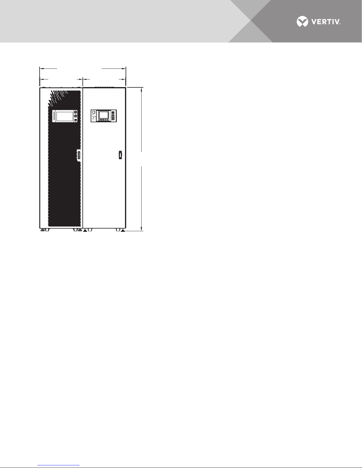
Figure 19 Lineup arrangement, Liebert EXM with Liebert EXM BDC
47.6" (1208mm)
23.6"
(600mm)
23.6"
(600mm)
NOTES
1. Dimensions are in inches (mm).
2. 24" (610mm) minimum clearance above unit.
36" (914mm) front access required for service.
For seismic mounting only 5" (102mm) in rear
for mounting brackets
3. Keep cabinet within 15 degrees of vertical.
4. Top and bottom cable entry available through removable
78.7"
(2000mm)
access plates.
Remove, punch to suit conduit size and replace.
5. Unit bottom is structurally adequate for forklift handling.
6. Control wiring and power wiring must be run in
separate conduits.
7. All wiring is to be in accordance with national and
local electrical codes.
8. Bypass distribution cabinet must be positioned on the right
side of the UPS.
UPS BDC
FRONT VIEW
EXM13028
Rev. 2
Vertiv | Liebert® EXM™ BDC User Manual | Rev. 3 | 01/18 | 25
Page 30

1. All dimensions are in inches (mm).
2. 24" (610) minimum clearance above unit; 36" (914) front access required for service.
3. Keep cabinet within 15 degrees of vertical.
4. Top and bottom cable entry available through removable access plates.
Remove, punch to suit conduit size and replace.
5. Control wiring and power wiring must be run in separate conduits.
6. All wiring is to be in accordance with national and local electrical codes.
Cable Entry Area
11.4" x 13.2"
(290 x 335mm)
Cable Entry Area
6.2" x 13.2"
(57 x 335mm)
6.5" (164mm)
Outside Panel
6.5" (164mm)
Outside Panel
11.5" (292mm)
Outside Panel
5.5"
(140mm)
34.6"
(870mm)
23.7"
(602mm)
23.6"
(600mm)
39.5" (1000mm)
78.7"
(2000mm)
28.3"
(719mm)
Bracket
Centers
6.4" (162mm)
Outside Panel
24"
(609mm)
FRONT
RIGHT SIDE
UAM06008
Rev. 5
Leveling
Feet
BOTTOM VIEW
TOP VIEW
Maximum
Door Swing - 120°
Figure 20 Outline drawing, Liebert EXM BDC for Liebert EXM, 10-100kVA
Vertiv | Liebert® EXM™ BDC User Manual | Rev. 3 | 01/18 | 26
Page 31
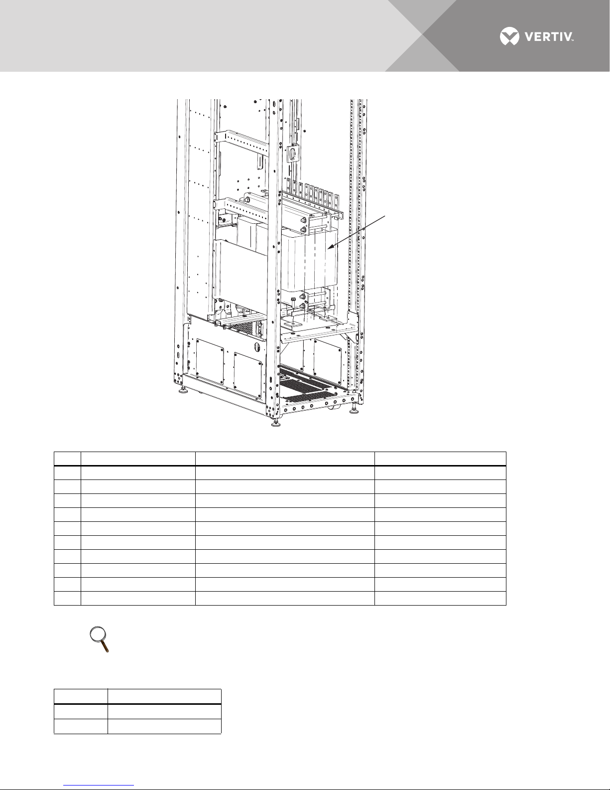
Figure 21 Liebert EXM BDC transformer location
Transformer
REAR OF CABINET
RIGHT SIDE
Table 4 Wiring for Liebert EXM to Liebert EXM BDC
Run From To Conductors
A Utility AC source BDC System Input Bus Phase A, B, C
B Utility AC Source BDC System Input Bus Neutral
C BDC Bypass Isolation Breaker UPS Main Input Phase A, B, C
D BDC Bypass Isolation Breaker UPS Main Input Neutral
E UPS Output Liebert EXM BDC Maintenance Isolation Breaker Phase A, B, C
F UPS Output Liebert EXM BDC Maintenance Isolation Breaker Neutral
G BDC Panelboard Load AC Connection Phase A, B, C
H BDC Panelboard Load AC Connection Neutral
I Utility AC Source All Ground Connections Ground
J BDC Terminal Block TB1 UPS Static Bypass Module J23, J24 and J26 Wiring for KO on Liebert EXM BDC
See Figure 4 and Tabl e 1 for additional details.
NOTE
Interconnection wiring between the UPS and bypass distribution cabinet is supplied by Vertiv when the
Liebert EXM BDC and Liebert EXM UPS are ordered as a system.
Table 5 Hardware torque values
Hardware Two Belleville Washers
M10 (3/8") 240 lb-in. (27 Nm)
M12 (1/2") 428 lb-in (48Nm)
Vertiv | Liebert® EXM™ BDC User Manual | Rev. 3 | 01/18 | 27
Page 32

Figure 22 One-line diagram, 208V single input 10-100kVA UPS with three-breaker Liebert EXM BDC and panelboard
MBB
BIB
MIB
BYPASS DISTRIBUTION CABINET
STATIC BYPASS
UPS CABINET
BIB - Bypass Isolation Breaker
MBB - Maintenance Bypass Breaker
MIB - Maintenance Isolation Breaker
* External Overcurrent Protection by Others
AC Output
208V
4 Wire + GND
(Optional)
54 Pole
See Note 6
* System
AC Input
4 Wire + GND
Field-Supplied Wiring
BATTERY
NOTES
1. Install in accordance with national and local electrical codes.
2. Input and bypass must share the same single source.
3. A neutral is required from the system AC input source.
4. UPS system input and output cables must be run in
separate conduits.
5. Control wiring must be run in separate conduits.
6. Optional 54 pole, 225A for 10-40kVA frame only or optional 54 pole
400A for 60-100kVA frame only.
EM11003
Rev. 0
Vertiv | Liebert® EXM™ BDC User Manual | Rev. 3 | 01/18 | 28
Page 33

Figure 23 One-line diagram, 208V single input 10-100kVA UPS with three-breaker Liebert EXM BDC, input isolation
transformer and panelboard
BYPASS DISTRIBUTION CABINET
* System
AC Input
3 Wire + GND
UPS CABINET
BATTERY
NOTES
1. Install in accordance with national and local electrical codes.
2. Input and bypass must share the same single source.
3. UPS system input and output cables must be run
in separate conduits.
4. Control wiring must be run in separate conduits.
5. Optional 54-pole, 225A for 10-40kVA frame only or
optional 54-pole 400A for 60-100kVA frame only.
6. Transformer available: 208, 220, 480, 600V input.
BIB MIB
MBB
STATIC BYPASS
(Optional)
54 Pole
See Note 5
BIB - Bypass Isolation Breaker
MBB - Maintenance Bypass Breaker
MIB - Maintenance Isolation Breaker
* External Overcurrent Protection by Others
Field-Supplied Wiring
AC Output
208V
4 Wire + GND
Local Grounding
Electrode
See Note 1
EXM1104
Rev. 0
Vertiv | Liebert® EXM™ BDC User Manual | Rev. 3 | 01/18 | 29
Page 34

Figure 24 One-line diagram, 208V single input 10-100kVA UPS with three-breaker Liebert EXM BDC and two subfeed
NOTES
1. Install in accordance with national and local electrical codes.
2. Input and bypass must share the same single source.
3. A neutral is required from the system AC input source.
Vertiv recommends a full capacity neutral conductor and
grounding conductors.
4.UPS system input and output cables must be run
in separate conduits.
5. Control wiring must be run in separate conduits.
6. Optional (2) 225A LDB for 60-100kVA frame only.
Optional single 225A LDB for 10-40kVA frame.
MBB
BIB
MIB
BYPASS DISTRIBUTION CABINET
STATIC BYPASS
UPS CABINET
LDB - Load Distribution Breaker
BIB - Bypass Isolation Breaker
MBB - Maintenance Bypass Breaker
MIB - Maintenance Isolation Breaker
* External Overcurrent Protection by Others
AC Output
208V
4 Wire + GND
Field-Supplied Wiring
EXM11005
Rev. 0
BATTERY
* System
AC Input
4 Wire + GND
LDB
LDB
(Optional)
(2) 225A
See Note 6
breakers
Vertiv | Liebert® EXM™ BDC User Manual | Rev. 3 | 01/18 | 30
Page 35

Figure 25 One-line diagram, 208V single input 60-100kVA UPS with three-breaker Liebert EXM BDC, input isolation
NOTES
1. Install in accordance with national and local electrical codes.
2. Input and bypass must share the same single source.
3. UPS system input and output cables must be run
in separate conduits.
4. Control wiring must be run in separate conduits.
5. Optional (2) 225A LDB for 60-100kVA frame only.
Optional single 225A LDB for 10-40kVA frame.
6. Transformer available: 208, 220, 480, 600V input.
MBB
BIB
MIB
BYPASS DISTRIBUTION CABINET
STATIC BYPASS
UPS CABINET
LDB - Load Distribution Breaker
BIB - Bypass Isolation Breaker
MBB - Maintenance Bypass Breaker
MIB - Maintenance Isolation Breaker
* External Overcurrent Protection by Others
AC Output
208V
4 Wire + GND
* System
AC Input
3 Wire + GND
Field-Supplied Wiring
EXM11006
Rev. 0
BATTERY
LDB
LDB
(Optional)
(2) 225A
See Note 5
Local Grounding
Electrode
See Note 1
transformer and two subfeed breakers
Vertiv | Liebert® EXM™ BDC User Manual | Rev. 3 | 01/18 | 31
Page 36

Figure 26 One-line diagram, 208V dual input 10-100kVA UPS with three-breaker Liebert EXM BDC and panelboard
NOTES
1. Install in accordance with national and local electrical codes.
2. Input and bypass must share the same single source.
3. A neutral is required from the system AC input source.
Vertiv recommends a full capacity neutral conductor.
4. Bypass and rectifier inputs and output cables
must be run in separate conduits.
5. Control wiring must be run in separate conduits.
6. Optional 54-pole, 225A for 10-40kVA frame only or
optional 54-pole 400A for 60-100kVA frame only.
7. Customer must supply shunt trip breaker with 120V coil.
8. Remove bypass jumper busbars inside the UPS to configure
a dual input system.
MBB
BIB MIB
BYPASS DISTRIBUTION CABINET
STATIC BYPASS
UPS CABINET
BIB - Bypass Isolation Breaker
MBB - Maintenance Bypass Breaker
MIB - Maintenance Isolation Breaker
* External Overcurrent Protection by Others
AC Output
208V
4 Wire + GND
* Rectifier
AC Input
4 Wire + GND
See Note 7
(Optional)
54 Pole
See Note 6
* Bypass
AC Input
4 Wire + GND
Field-Supplied Wiring
EXM11007
Rev. 0
BATTERY
See Tables 12 and13 for
details.
Vertiv | Liebert® EXM™ BDC User Manual | Rev. 3 | 01/18 | 32
Page 37

Figure 27 One-line diagram, 208V dual input 10-100kVA UPS with three-breaker Liebert EXM BDC and two subfeed breakers
See Tables 12 and13 for
details.
* Bypass
AC Input
4 Wire + GND
* Rectifier
AC Input
4 Wire + GND
See Note 7
BYPASS DISTRIBUTION CABINET
STATIC BYPASS
UPS CABINET
BATTERY
MBB
LDB
LDB
MIBBIB
(Optional)
(2) LDB
See Note 6
AC Output
208V
4 Wire + GND
Notes
1. Install in accordance with national and local electrical codes.
2. Input and bypass must share the same single source.
3. A neutral is required from the system AC input source.
Vertiv recommends a full capacity neutral conductor and
grounding conductors.
4. Bypass and rectifier inputs and output cables
must be run in separate conduits.
5. Control wiring must be run in separate conduits.
LDB - Load Distribution Breaker
BIB - Bypass Isolation Breaker
MBB - Maintenance Bypass Breaker
MIB - Maintenance Isolation Breaker
* External Overcurrent Protection By Others
Field-Supplied Wiring
EXM11008
Rev. 0
6. Optional (2) 225A LDB for 60-100kVA frame only.
7. Customer must supply shunt trip breaker with 120V coil.
8. Remove bypass jumper busbars inside the UPS to configure
a dual input system.
Vertiv | Liebert® EXM™ BDC User Manual | Rev. 3 | 01/18 | 33
Page 38

3.0 SPECIFICATIONS
Table 6 Physical standards and parameters
Bypass Distribution Cabinet Parameters Values
Standard Color Black (ZP-7021)
Front Door Opening (for serviceability)
Degree of Protection for UPS Enclosure
Minimum Clearance, Top 24" (610mm)
Minimum Clearance, Back 0" (5" [127mm] when seismic brackets are used)
Minimum Clearance, Sides 0"
Standards & Conformities
Environmental
Storage Temperature Range, °F (°C) -13°F to 158°F (-25°C to 70°C)
Operating Temperature Range, °F (°C)
Relative Humidity
Maximum Altitude Above MSL, ft (m)
IP 20 (with and without front door open)
Cable Entrance Top or Bottom
UL 1778 5th Ed.; CSA 22.2 107.3-14
FCC Part 15, Class A; ISTA Procedure 1H; WEEE;
32°F to 86°F (0-30°C) when seismic brackets are used
4920 (1500) (as per IEC 62040/3) -
1% Maximum kW derate / 100m rise between 1500-3000m
More than 180°
IBC 2012/CBC 2010
32°F to 104°F (0 to 40°C)
up to 95% Non-Condensing
(Operating and Non-Operating)
The following are approved branch breakers for the panel boards used in the EXM BDC.
Listed (DIVQ), Schneider Electric Square D branch circuit breakers:
• Type QOB, rated 22 kA, 150 A maximum
• Type QO, rated 22 kA, rated 100 A maximum
• Type QOB, rated 10 kA, rated 100 A maximum
• Type QO, rated 10 kA, rated 100 A maximum
Table 7 Mechanical characteristics, Liebert EXM BDC, 10-100kVA
Dimensions, W x D x H, in (mm)
Frame SizemmRating
kVA
600 10-40 525 (238) 625 (283) 914 (415) 1014 (460)
600 60 550 (249) 650 (295) 1123 (509) 1223 (555)
600 80 550 (249) 650 (295) 1249 (567) 1349 (612)
600 100 550 (249) 650 (295) 1365 (619) 1465 (665)
Add 27 lb. (12 kg) for monitoring.
No Transformer
No Distribution
23.625 x 39.375 x 78.73
Weight, lb. (kg)
No Transformer With
Panel Board or
Subfeed Breaker
With Transformer
No Distribution
With Transformer
and Panel Board or
Subfeed Breaker
Vertiv | Liebert® EXM™ BDC User Manual | Rev. 3 | 01/18 | 34
Page 39

Table 8 Liebert EXM BDC, 60-100kVA, mechanical characteristics
Rated Power, kVA 60-100
Dimensions, W x D x H, in (mm) 23.625 x 39.375 x 78.75 (600 x 1000 x 2000)
Weight, lb (kg)
No Distribution 550 (250)
Two 225A Subfeed Breakers 660 (300)
400A Panelboard 660 (300)
No Distribution & 480V Transformer 1549 (704)
No Distribution & 600V Transformer 1538 (699)
Two 225A Subfeed Breakers & 480V Transformer 1669 (759)
Two 225A Subfeed Breakers & 600V Transformer 1648 (749)
400A Panelboard & 480V Transformer 1669 (759)
400A Panelboard & 600V Transformer 1648 (749)
Color ZP 7021 (Black)
Protection Degree IEC (60529) IP20 (finger-proof with front doors open or closed)
Table 9 Liebert EXM BDC heat dissipation
Liebert EXM BDC
Liebert EXM BDC
Rating, kVA
10 1966 (0.576) 1808 (0.530) 1723 (0.505) 1750 (0.513)
15 2504 (0.734) 2320 (0.680) 2474 (0.725) 2453 (0.719)
20 2938 (0.861) 2593 (0.760) 2958 (0.867) 2986 (0.875)
30 4847 (1.421) 4408 (1.292) 4343 (1.273) 4896 (1.435)
40 5676 (1.664) 5166 (1.514) 5005 (1.467) 4988 (1.462)
60 7479 (2.192) 6804 (1.994) 6670 (1.955) 6445 (1.899)
80 9612 (2.817) 8711 (2.553) 9001 (2.638) 8892 (2.606)
100 9728 (2.851) 8881 (2.603) 9953 (2.917) 10042 (2.943)
Heat Dissipation
208:208 Transformer
BTU/Hr (kW)
Liebert EXM BDC
Heat Dissipation
220:220 Transformer
BTU/Hr (kW)
Liebert EXM BDC
Heat Dissipation
480:208 Transformer
BTU/Hr (kW)
Liebert EXM BDC
Heat Dissipation
600:208 Transformer
BTU/Hr (kW)
Vertiv | Liebert® EXM™ BDC User Manual | Rev. 3 | 01/18 | 35
Page 40

3.1 Electrical Characteristics
NOTE
The breakers and cables used must be in accordance with NEC ANSI/NFPA 70. A disconnect breaker must be
provided for AC input, Bypass and AC output. Recommended cable sizes are suitable for operation at a
maximum temperature of 104°F (40°C).
Table 10 Liebert EXM BDC input currents, single input, main, without transformer
Vol tag e
3-Ph, 60 Hz
208/120
220/127
208/120
220/127
208/120
220/127
208/120
220/127
208/120
220/127
208/120
220/127
208/120
220/127
208/120
220/127
BDC Rating
kVA
10 34 3W + N + G 45 65 (1) #6 (1) #4 M12
15 51 3W + N + G 70 85 (1) #4 (1) #2 M12
20 68 3W + N + G 90 115 (1) #2 (1) 1/0 M12
30 102 3W + N + G 150 175 (1) 2/0 (1) 4/0 M12
40 136 3W + N + G 175 230 (1) 4/0 (2) 1/0 M12
60 205 3W + N + G 300 400 (2) 3/0 (2) 4/0 M12
80 273 3W + N + G 350 460 (2) 4/0 (2) 300kcmil M12
100 341 3W + N + G 450 610 (2) 350kcmil (2) 400kcmil M12
System Input
Current, A, Max Phase
Recommended
Upstream
Protection, A
75°C Wire
Current, A, Total Copper Wire
Aluminum
Wire Bolt Size
Table 11 Liebert EXM BDC input currents, dual input, rectifier, without transformer
Rectifier
Vol tag e
3-Phase, 60Hz
208/120
220/127
208/120
220/127
208/120
220/127
208/120
220/127
208/120
220/127
208/120
220/127
208/120
220/127
208/120
220/127
Refer to Figures 26 and27 for additional details about this system configuration.
BDC Rating,
kVA
10 34 45 3W + N + G 65 (1) #6 (1) #4 M12
15 51 70 3W + N + G 85 (1) #3 (1) #2 M12
20 68 90 3W + N + G 115 (1) #2 (1) 1/0 M12
30 102 150 3W + N + G 175 (1) 2/0 (1) 4/0 M12
40 136 175 3W + N + G 230 (1) 4/0 (2) 1/0 M12
60 205 300 3W + N + G 400 (2) 3/0 (2) 4/0 M12
80 273 350 3W + N + G 460 (2) 4/0 (2) 300kcmil M12
100 341 450 3W + N + G 610 (2) 350kcmil (2) 400kcmil M12
Rectifier Input
Current RIB, A, Max
Recommended
Upstream
Protection, A Phase
75°C Wire
Current, A, Total Copper Wire
Aluminum
Wire Bolt Size
Vertiv | Liebert® EXM™ BDC User Manual | Rev. 3 | 01/18 | 36
Page 41

Table 12 Liebert EXM BDC input currents, dual input, bypass, without transformer
Vol tag e
3-Ph, 60 Hz
208/120
220/127
208/120
220/127
208/120
220/127
208/120
220/127
208/120
220/127
208/120
220/127
208/120
220/127
208/120
220/127
Refer to Figures 26 and27 for additional details about this system configuration.
BDC Rating
kVA
10 28 40 3W + N + G 50 (1) #6 (1) #4 M12
15 42 70 3W + N + G 85 (1) #4 (1) #2 M12
20 56 80 3W + N + G 115 (1) #2 (1) #2 M12
30 83 125 3W + N + G 130 (1) 1/0 (1) 2/0 M12
40 111 175 3W + N + G 175 (1) 3/0 (1) 4/0 M12
60 167 250 3W + N + G 285 (1) 350kcmil (2) 2/0 M12
80 222 350 3W + N + G 400 (2) 3/0 (2) 4/0 M12
100 278 450 3W + N + G 460 (2) 4/0 (2) 300 kcmil M12
Bypass Input
Current
BIB/MBB, A, Max
Bypass Recommended
Upstream Protection, A Phase
75°C Wire
Current, A Total
Table 13 Liebert EXM BDC output currents
Vol tag e
3-Ph, 60Hz)
208/120
220/127
208/120
220/127
208/120
220/127
208/120
220/127
208/120
220/127
208/120
220/127
208/120
220/127
208/120
220/127
System
BDC
Rating, kVA
10 28 3W + N + G 40 50 (1) #6 (1) #4 M12
15 42 3W + N + G 60 85 (1) #4 (1) #2 M12
20 56 3W + N + G 70 115 (1) #2 (1) #2 M12
30 83 3W + N + G 110 130 (1) 1/0 (1) 2/0 M12
40 111 3W + N + G 150 175 (1) 3/0 (1) 4/0 M12
60 167 3W + N + G 225 285 (1) 350kcmil (2) 2/0 M12
80 222 3W + N + G 300 400 (2) 3/0 (2) 4/0 M12
100 278 3W + N + G 350 460 (2) 4/0 (2) 300kcmil M12
Output
Current
A, Max Phase
Recommended
Upstream
Protection, A
75°C
Wire
Current
A, Total
Copper
Wire
Copper
Wire
Aluminum
Wire
Aluminum
Wire Bolt Size
Bolt
Size
Vertiv | Liebert® EXM™ BDC User Manual | Rev. 3 | 01/18 | 37
Page 42

Table 14 Recommended lug sizes (compression type) M12, 1/2" bolt
Cable Size
#6AWG 256-030695-868 —
#4AWG 256-030695-733 —
#2-3AWG 54811BE —
#1AWG 54857BE —
#1/0AWG 256-30695-593 —
#2/0AWG 54862BE 60238
#3/0AWG 54864BE 60244
#4/0AWG 54866BE 60250
250kcmil 54868BE 60256
300kcmil 54870BE 60262
350kcmil 54872BE 60267
400kcmil 54874BE 60269
500kcmil 54876BE 60273
600kcmil 54878BE 60275
700kcmil 54879BE 60277
750kcmil 54880BE 60278
T&B Copper
Two Hole
T&B Aluminum
Two Hole
3.2 Torque Requirements
All electrical connections must be tight.
Tables 15 and16 provide the torque values for the connections to the Liebert EXM BDC. Use these values unless
the equipment is labeled otherwise.
Table 15 Busbar torque for power wiring
Bolt Shaft Size
3/8" (M10) 192 (22)
1/2" (M12) 428 (48)
Tor qu e
Lb-in (Nm)
Table 16 Terminal block torque with compression lugs for control wiring
AWG W ire Size
or Range
#22 - #14 3.5 to 5.3 (0.4 to 0.6)
Tor qu e
Lb-in (Nm)
NOTE
Refer to the manufacturer’s data for proper torque for circuit breaker power connections.
Vertiv | Liebert® EXM™ BDC User Manual | Rev. 3 | 01/18 | 38
Page 43

Table 17 Breaker torque
Manufacturer Part Number Torque, Nm
Tma x2 7.0
Tma x3 8.0
ABB
Siemens
Tma x5 25 .0
XT1 6
XT3 8
D Frame 5.5
F Frame 22.0
J Frame 31.0
Table 18 Electrical data—Liebert EXM BDC, 480VAC input, 208VAC output, single input, with 480V:208V transformer
Liebert EXM
BDC Rating, kVA
10 15 3W + G 20 40 (1) #8 (1) #8 M12
15 23 3W + G 30 40 (1) #8 (1) #8 M12
20 31 3W + G 40 40 (1) #8 (1) #8 M12
30 46 3W + G 60 65 (1) #6 (1) #4 M12
40 61 3W + G 80 85 (1) #4 (1) #2 M12
60 91 3W + G 125 150 (1) #2 (1) 1/0 M12
80 122 3W + G 175 200 (1) 1/0 (1) 3/0 M12
100 152 3W + G 200 205 (1) 4/0 (1) 250 kcmil M12
See Notes on Tables 18 through20. on page 40.
Maximum System
Input Current, A Phase
Recommended
Upstream
Protection, A
75°C Wire
Current, A, Total Copper Wire
Aluminum
Wire Bolt Size
Table 19 Electrical data—Liebert EXM BDC, 600VAC input, 208VAC output, single input, with 600V:208V transformer
Liebert EXM
BDC Rating, kVA
10 12 3W + G 20 40 (1) #8 (1) #8 M12
15 18 3W + G 25 40 (1) #8 (1) #8 M12
20 25 3W + G 35 40 (1) #8 (1) #8 M12
30 37 3W + G 50 50 (1) #8 (1) #6 M12
40 49 3W + G 70 65 (1) #5 (1) #4 M12
60 73 3W + G 100 90 (1) #3 (1) #2 M12
80 98 3W + G 125 120 (1) #1 (1) 1/0 M12
100 122 3W + G 175 150 (1) 1/0 (1) 3/0 M12
See Notes on Tables 18 through20. on page 40.
Maximum System
Input Current, A Phase
Recommended
Upstream
Protection, A
75°C Wire
Current, A, Total Copper Wire
Aluminum
Wire Bolt Size
Table 20 Electrical data—Liebert EXM BDC, 208VAC or 220VAC input, single input, with 208V:208V or 220V:220V
transformer
Liebert EXM
BDC Rating, kVA
10 36 3W + G 45 65 (1) #6 (1) #4 M12
15 53 3W + G 70 85 (1) #4 (1) #2 M12
20 71 3W + G 90 100 (1) #3 (1) #1 M12
30 107 3W + G 150 175 (1) 2/0 (1) 4/0 M12
Maximum System
Input Current, A Phase
Recommended
Upstream
Protection, A
75°C Wire
Current, A, Total Copper Wire
Aluminum
Wire Bolt Size
Vertiv | Liebert® EXM™ BDC User Manual | Rev. 3 | 01/18 | 39
Page 44

Table 20 Electrical data—Liebert EXM BDC, 208VAC or 220VAC input, single input, with 208V:208V or 220V:220V
transformer
Liebert EXM
BDC Rating, kVA
40 141 3W + G 200 230 (1) 4/0 (1) 300 kcmil M12
60 211 3W + G 300 335 (1) 400 kcmil (2) 4/0 M12
80 281 3W + G 400 460 (2) 4/0 (2) 300 kcmil M12
100 352 3W + G 450 510 (2) 250 kcmil (2) 400 kcmil M12
See Notes on Tables 18 through20. below.
Maximum System
Input Current, A Phase
Recommended
Upstream
Protection, A
75°C Wire
Current, A, Total Copper Wire
Aluminum
Wire Bolt Size
Notes on Tables 18 through20.
1. Nominal input current (considered continuous) is based on full rated output load maximum current includes nominal input
current and maximum battery recharge current (considered noncontinuous). Continuous and noncontinuous current are
defined in NEC 100. Recommended overcurrent protection is based on 80% rated devices.
*The recommended overcurrent protection represents 125% of nominal full load current (continuous) per NEC 215.
2. Maximum input current is controlled by the current limit setting.
3. Recommended AC input external overcurrent protection is based on 80% rated devices and maximum input current limit
setting.
4. Recommended AC output external overcurrent protection is based on 80% rated devices and full rated output current.
5. Nominal battery voltage is shown at 2 volts per cell.
6. Input power factor of 0.99 is used for the calculations.
Vertiv | Liebert® EXM™ BDC User Manual | Rev. 3 | 01/18 | 40
Page 45

Notes
Vertiv | Liebert® EXM™ BDC User Manual | Rev. 3 | 01/18 | 41
Page 46

Vertiv | Liebert® EXM™ BDC User Manual | Rev. 3 | 01/18 | 42
Page 47

TECHNICAL SUPPORT / SERVICE
Web Site
www.vertivco.com
Monitoring
liebert.monitoring@vertivco.com
800-222-5877
Outside North America: +00800 1155 4499
Three-Phase UPS & Power Systems
800-543-2378
Outside North America: 614-841-6598
LOCATIONS
United States
1050 Dearborn Drive
P.O. B ox 2 918 6
Columbus, OH 43229
Europe
Via Leonardo Da Vinci 8
Zona Industriale Tognana
35028 Piove Di Sacco (PD) Italy
+39 049 9719 111
Fax: +39 049 5841 257
Asia
29/F, The Orient Square Building
F. Ortigas Jr. Road, Ortigas Center
Pasig City 1605
Philippines
+63 2 687 6615
Fax: +63 2 730 9572
Page 48

VertivCo.com | Vertiv Headquarters, 1050 Dearborn Drive, Columbus, OH, 43085, USA
© 2016 Vertiv Co. All rights reserved. Vertiv and the Vertiv logo are trademarks or registered trademarks of Vertiv Co. All other names and logos referred to are trade names, trademarks or registered trademarks of their respective owners.
While every precaution has been taken to ensure accuracy and completeness herein, Vertiv Co. assumes no responsibility, and disclaims all liability, for damages resulting from use of this information or for any errors or omissions. Specifications are subject to
change without notice.
SL-25653_REV3_01-18
 Loading...