

Page 1

INSTALLATION,
O
PERATION AND
MAINTENANCE
MANUAL
TRANSIENT VOLTAGE SURGE SUPPRESSION
AccuVar ACV
Liebert
Page 2

Surge
®
Suppression
Systems
LIEBERT ACCUVAR® ACV SERIES
INSTALLATION, OPERATION, AND MAINTENANCE MANUAL
TABLE OF CONTENTS
UNPACKING AND INSTALLATION
Unpacking and Preliminary Inspection......................................................................................3
Storage...........................................................................................................................................3
Location Considerations..............................................................................................................3
ELECTRICAL CONNECTIONS
Voltage Ratings & Power Source Configurations....................................................................4
Overcurrent Protection .................................................................................................................4
Connection.....................................................................................................................................5
System Grounding & Bonding....................................................................................................5
OPERATION.......................................................................................................................................7
Summary Alarm Contact Option................................................................................................7
TROUBLESHOOTING / MAINTENANCE / SERVICING
Inspection and Cleaning..............................................................................................................7
Troubleshooting............................................................................................................................7
Corrective Maintenance...............................................................................................................7
Servicing ........................................................................................................................................7
LIMITED WARRANTY.......................................................................................................................9
DECLARATION OF CONFORMITY..............................................................................................11
FIGURES
Figure 1. AccuVar ACV Series Dimensions............................................................................2
Figure 2. Installation Diagram...................................................................................................8
TABLES
Table 1. Terminal Wire Size Range & Suggested Wiring Overcurrent Protection............4
Table 2. Voltage Ratings & Power Source Configurations...................................................6
Installation, Operation ACV Series
and Maintenance Manual - 1 - Rev 2, 3/00
Page 3

Surge
®
Suppression
Systems
INSTALLATION INSTRUCTIONS FOR THE LIEBERT
ACCUVAR® ACV SERIES SURGE PROTECTIVE DEVICE
WITH OPTIONAL FILTERING
The Liebert AccuVar® ACV Series Surge
Protective Device (SPD) is a high quality, high
energy surge current diversion system designed to
protect sensitive equipment from damaging
transient surges and electrical line noise. Proper
installation is required for maximum system
performance.
The installer should perform the following steps to
assure a quality installation. The entire installation
manual should be read before starting installation.
These instructions do not replace national or local
electrical codes. Check applicable electrical codes
to ensure compliance. Installation of the Liebert
AccuVar ACV Series Surge Protective Device
should only be performed by qualified personnel.
Figure 1. AccuVar ACV Series Dimensions.
Installation, Operation ACV Series
and Maintenance Manual - 2 - Rev 2, 3/00
Page 4

Surge
®
UNPACKING AND INSTALLATION
Suppression
Systems
Unpacking and Preliminary Inspection
1. Inspect the shipping crate(s) for damage or
signs of mishandling before unpacking the
unit.
2. If any damage as a result of shipping is
observed, immediately file a claim with the
shipping agency and forward a copy to your
local Liebert Sales Representative.
Storage
The unit should be stored in a clean, dry
environment. Storage temperature range is -55ºC
(-67ºF) to +85ºC (+185ºF). Care should be taken
to avoid condensation. All packing and shipping
materials should be left intact until the unit is
ready for final installation. If the unit has been
stored for an extended period of time, the unit
should be cleaned and carefully inspected before
placing into service.
Location Considerations
Environment – The unit is designed for operation
indoors in ambient temperatures of -40ºC (-40ºF)
to +50ºC (+122ºF) with a relative humidity of 0%
to 95% (non-condensing).
The cover screws and “O” rings are supplied inside
of the unit in the small plastic bag that also
contains the wiring ring terminals. To properly
attach the cover to the enclosure the four “O” rings
must be used with the four screws provided, prior
to placing the screw in hole of cover. Screws
should be torqued between 4 and 10 inch-pounds.
Note: To maintain the integrity of the “O”
rings, protection against direct sunlight is
advised.
Equipment Performance – For maximum system
performance, the unit must be located as close to
the protected circuit as practical to minimize
interconnecting wiring length.
For optimum transient surge protection,
coordinated surge suppression should be applied at
the service entrance, at all other electrical
connections to the building (telephone, CATV,
etc.), and at known transient surge generating
loads within the building (large motors, arc
welders, switched capacitors, etc.). Electrical line
noise protection should also be applied close to the
point of usage for sensitive electronic loads
(computers, electronic appliances, solid state
motor drives, etc.). For interconnected electronic
loads (such as by way of data cabling),
communication line protectors may also be applied
to the interconnect wiring.
The unit is provided in a NEMA 12, 4, and 4X
rated industrial use enclosure, which is dust, drip,
and water tight and should not be installed in areas
with flammable materials or explosive
atmospheres.
Outdoor Use – To assure water tightness for
outdoor use, “O” rings must be used with screws
to secure cover!
Installation, Operation ACV Series
and Maintenance Manual - 3 - Rev 2, 3/00
Mounting – The unit is to be wall mounted. Refer
to Figure 1 for mounting dimensions.
Page 5
Surge
®
WARNING
!!
ELECTRICAL CONNECTIONS
Suppression
Systems
All electrical connections should be installed by a
qualified (licensed) electrician only. All wiring
must comply with the National Electrical Code
(NEC) and applicable local codes.
VERIFY THAT ALL POWER
CIRCUITS ARE DE-ENERGIZED AND
LOCKED OUT BEFORE MAKING
ELECTRICAL CONNECTIONS.
Terminals are provided inside the Liebert AccuVar
SPD units for the line (phase), neutral (if used),
and transient ground connections.
Voltage Ratings &
Power Source Configurations
Before making connections to the unit, verify that
the unit model number and nameplate voltage
rating are appropriate for connection to the
intended power source. See Figure 2 for voltage
rating applications with typical power source
configurations and assure that system voltages do
not exceed the maximum continuous operating
voltage (MCOV) on the unit’s data label.
Surge Voltage Ratings – To obtain the
suppression voltage ratings (SVRs), as obtained by
Underwriters Laboratories, Incorporated, in
accordance with the Standard for Safety, Surge
protective devices, (SPD), Standard 1449, Second
Edition, dated August 15, 1996, marked on this
product, #10 AWG wire must be utilized to
connect the AccuVar® to your facilities’ power
grid. Connections made with other that #10 AWG
conductors may result in different suppression
voltage ratings.
Circuit Ampacity Limitations – Representative
samples of this device have been investigated by
Underwriters Laboratories, Incorporated to
withstand, without exposing live circuits or
components on power sources, with voltage of two
times (2x) the device ratings, and fault currents of
up to 300,000 AIC, as described in the Standard
for Safety, Surge protective devices, (SPD),
Standard 1449, Second Edition, dated August 15,
1996.
Overcurrent Protection
The SPD unit conducts practically no current
under normal operation and only conducts during
very short duration transient conditions. The
Liebert AccuVar ACV Series SPD units contain
UL approved 300 kAIC internal system fusing to
protect against device failure. This overcurrent
protection, while not currently required by SPD
safety agencies or installation codes (NEC Article
280), has proven to be prudent engineering
practice.
External overcurrent protection is not specifically
required, nor is it desired since it impedes the
performance of the transient surge suppressor. If
overcurrent protection of the conductors to the
transient surge suppressor is desired, the suggested
fuse sizes based on the unit’s transient surge
current capabilities and suggested wire sizes are
shown in Table 1.
Table 1. Terminal Wire Size Range and Suggested Wiring Overcurrent Protection (All Models).
SUGGESTED
WIRE SIZE
(AWG)
10* 6-32 screw ring or spade terminal required. 30A
12 (Spare terminal screws enclosed) 20A
Installation, Operation ACV Series
and Maintenance Manual - 4 - Rev 2, 3/00
SPECIAL NOTES
* Must be used for UL1449 performance.
SUGGESTED
FUSE / CIRCUIT BREAKER
AMPACITY (IF USED)
Page 6

Surge
®
Suppression
Systems
Connection
With the AccuVar’s parallel connection, the length
of wiring to the transient voltage surge suppression
(SPD) unit must be minimized for best
performance. Wire lengths longer than 10 feet
must be avoided. Wiring connections may be
made directly into circuit breakers.
To reduce the wiring impedance to surge currents,
the phase, neutral (if required), and ground
conductors are recommended to be twisted
together and routed in the same raceway (conduit).
Avoid any sharp bends in the conductors.
Wire Sizing - With parallel connection, the size of
the wiring to the SPD unit is independent of the
protected circuit’s ampacity. Suggested wire sizes
based on the unit’s transient surge current
capabilities are shown in Table 1.
System Grounding & Bonding
The performance and safety of any SPD system is
dependent on proper grounding. Grounding is
required primarily for safety. Correct
implementation also enhances equipment
performance. Incorrect grounding can reduce or
impede the SPD’s operation.
All electrical circuits to or from the SPD must
include an equipment grounding conductor as
required by the NEC and local codes.
An insulated grounding conductor is recommended
for the SPD. The grounding conductor should be
the same wire size as the associated power
conductors and should be connected in close
proximity to the SPD.
Grounding Electrode – Contrary to popular
belief, transient surge suppressors do not discharge
all surges to ground (earth). Transient surge
suppressors divert the surge current back to its
source to complete the electrical circuit.
In the case of lightning, whose potential is
developed with respect to the earth, the SPD
diverts the surge current to the grounding electrode
(earth connection). However, for most transient
surges which are developed by switching loads,
the SPD diverts the surge current back to its source
without involving the grounding electrode.
For proper SPD performance, the service entrance
grounding electrode system must comply with the
NEC by having all available electrodes (building
steel, metal water pipe, driven rods, concrete
encased electrodes, etc.) properly bonded together
and connected to the power system grounding.
The use of a separate grounding electrode to
ground the SPD defeats the effectiveness of the
SPD, is a potential safety hazard, may cause
equipment damage, is an NEC violation
(reference NEC 250-51 and 250-54), and is not
recommended.
Installation, Operation ACV Series
and Maintenance Manual - 5 - Rev 2, 3/00
Page 7
Surge
®
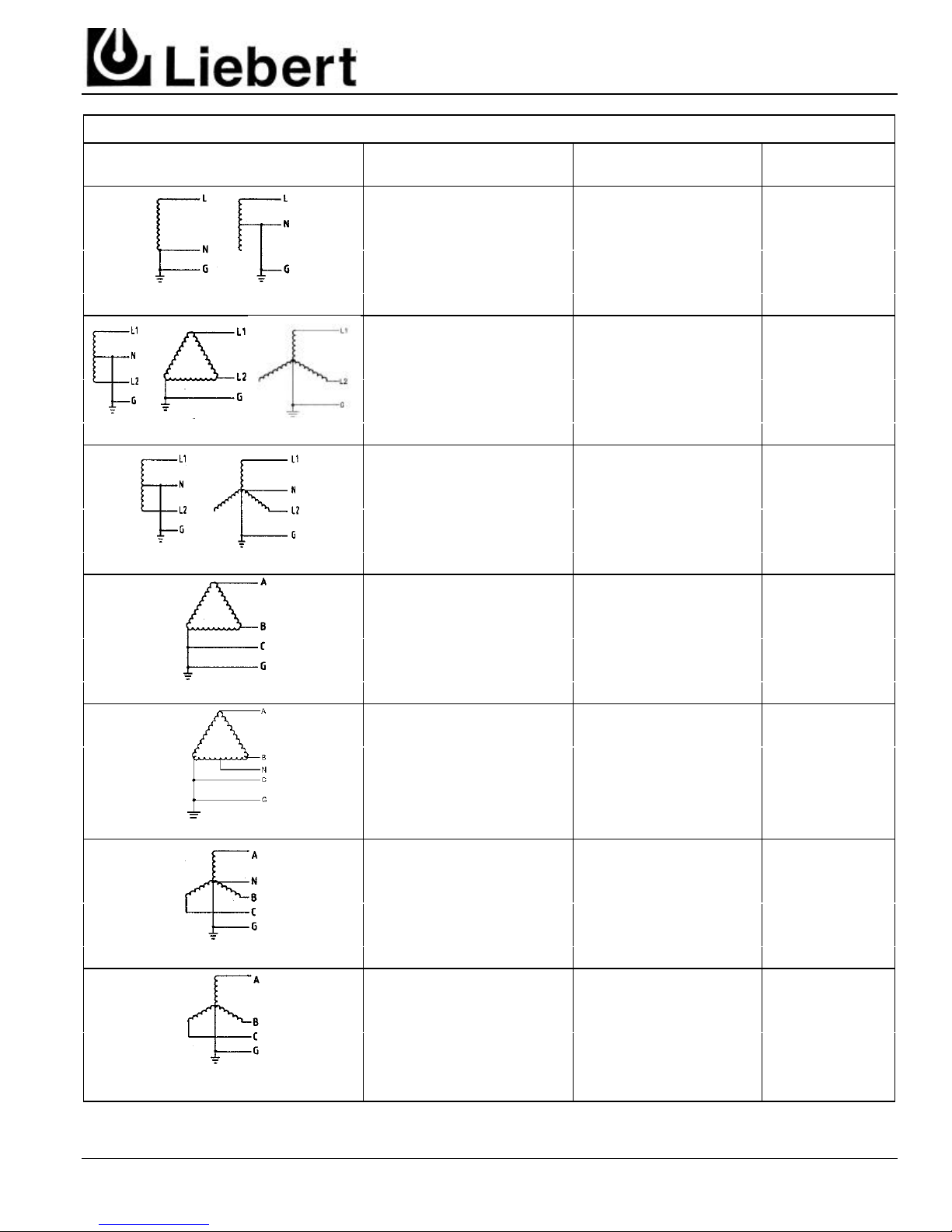
Split Single Phase, 3 W + G
Single Phase L-N, 2 W +G
Three Phase Wye, 3 W + G
VOLTAGE RATINGS & POWER SOURCE CONFIGURATIONS
Suppression
Systems
Source Configurations
Single Phase L-L, 2 W + G
Three Phase Delta, 3 W + G
Nominal
Operating Voltage
Maximum Continuous
Operating Voltage
Model Voltage
Code
100 130 L-N 100N
110 130 L-N 110N
120 150 L-N 120N
230 275 L-N 230N
277 320 L-N 277N
347 420 L-N 347N
208 130 L-L 208L
240 150 L-L 240L
400 275 L-L 400L
480 275 L-L 480L
600 420 L-L 600L
120 / 208 or 120 / 240 150 L-N 120S
277 / 480 320 L-N 277S
347 / 600 420 L-N 347S
208 250 L-L 208D
240 320 L-L 240D
380 420 L-L 380D
415 580 L-L 415D
480 580 L-L 480D
600 680 L-L 600D
120 / 240 150 L-N 240H
208 / 240 250 L-N 240H
Three Phase Delta Hi Leg, 4 W + G
Three Phase Wye, 4 W + G
No Neutral
Table 2. Voltage Ratings and Power Source Configurations.
For other voltages or source configurations, consult factory.
Installation, Operation ACV Series
and Maintenance Manual - 6 - Rev 2, 3/00
120 / 208 150 L-N 120Y
220 / 380 320 L-N 220Y
240 / 415 320 L-N 240Y
277 / 480 320 L-N 277Y
347 / 600 420 L-N 347Y
120 130 L-L 120Y
230 275 L-L 230Y
277 320 L-L 277Y
347 420 L-L 347Y
Page 8

Surge
®
WARNING
!!
Suppression
Systems
OPERATION
Liebert AccuVar ACV Series SPD Systems
require little or no operator intervention after
installation. The units are provided with status
LED, which assist in determining when the unit
needs service (see Troubleshooting/Repair/
Maintenance Section).
If the unit is energized and the green LED is off
(and / or the red LED is on), the AccuVar is not
fully functional and will require replacement.
Summary Alarm Contact Option
Optional Form C ( 1 N.O. and 1 N.C.) relay
contacts may be provided for remote indication of
TROUBLESHOOTING / MAINTENANCE / SERVICING
Inspection and Cleaning
Periodic system inspections, cleaning, and
connection checks are recommended to ensure
reliable system performance and continued
transient protection.
(For any other problems not listed below, or if
cause of the problem cannot be determined,
please call Control Concepts at 800-288-6169 or
607-724-2484.)
phase loss, undervoltage (70% of line voltage,
typical), power loss, and suppression failure. If the
status of the contacts change (indicating a
problem), one of these conditions exists.
The summary alarm contact terminals are located
inside the unit. Contacts are rated for 5 amps at
125 VAC maximum.
Note: Wiring for the Form C contacts may be
routed through the flexible conduit with the phase
wiring. All wire must comply with the National
Electrical Code (NEC) and applicable local codes.
provided to indicate when the unit needs
replacement (see operation section of this manual
for details). To ensure continuity of surge
protection, failed units should be replaced at the
earliest convenient service opportunity.
Servicing
Troubleshooting
If status failure indication occurs or Form C relay
has changed states, a qualified electrician should
first determine if the systems voltage and proper
phasing exists.
If the AccuVar SPD remains in an alarm condition
once the technician is satisfied that the electrical
system and its connections are normal, the unit
should be replaced.
Corrective Maintenance
The Liebert AccuVar ACV Series SPD is designed
for years of trouble-free operation. However, even
the most reliable equipment may fail under
abnormal conditions. Diagnostic indicators are
Installation, Operation ACV Series
and Maintenance Manual - 7 - Rev 2, 3/00
ONLY QUALIFIED PERSONNEL
SHOULD PERFORM MAINTENANCE
ON THE SYSTEM.
HAZARDOUS VOLTAGES ARE
PRESENT INSIDE THE UNIT DURING
NORMAL OPERATIONS.
ELECTRICAL SAFETY PRECAUTIONS MUST BE FOLLOWED
WHEN SERVICING THIS UNIT.
TO PREVENT RISK OF ELECTRICAL
SHOCK, TURN OFF AND LOCK OUT
ALL POWER SOURCES TO THE UNIT
BEFORE SERVICING UNIT.
Page 9

Surge
®
Suppression
Systems
*
*
Figure 2. Installation Diagram.
*If neutral is provided, a reliable neutral must be pulled to the AccuVar.
Installation, Operation ACV Series
and Maintenance Manual - 8 - Rev 2, 3/00
Page 10

Surge
®
Suppression
Systems
LIMITED WARRANTY
This Warranty is given ONLY to purchasers who buy for commercial or industrial use in the ordinary course of each purchaser's business.
General:
Control Concepts' products are in our opinion the finest available. We take pride in our products and are pleased that you have chosen them. Under certain
circumstances, we offer with our products the following Five-Year Warranty Against Defects in Material and Workmanship. Please read your Warranty carefully.
This Warranty sets forth our responsibilities in the unlikely event of defect and tells you how to obtain performance under this Warranty.
FIVE YEAR LIMITED WARRANTY AGAINST DEFECTS IN MATERIAL AND WORKMANSHIP
CONTROL CONCEPTS PRODUCTS COVERED: AccuVar®.
Terms of Warranty:
As provided herein, the Control Concepts product is warranted to be free of defects in material and workmanship for a period of five (5) years from the date of
delivery of the product to User. The delivery date will be determined only from the Control Concepts bill of lading. If any of the Control Concepts products fail to
conform to the warranty within the warranty period, Control Concepts, at its option, will furnish new or factory remanufactured parts for repair or replacement of
that part.
Warranty Extends to First Purchaser for Use, Non-transferable:
This Warranty is extended to the first person, firm, association or corporation for whom the Control Concepts product specified herein is originally installed for
use in the United States (the "User"). This Warranty is not transferable or assignable without the prior written permission of Control Concepts.
Assignment of Warranties:
Control Concepts assigns to User any warranties which are made by manufacturers and suppliers of components of the Control Concepts product and which are
assignable, but Control Concepts makes NO REPRESENTATIONS as to the effectiveness or extent of such warranties, assumes NO RESPONSIBILITY for any
matters which may be warranted by such manufacturers or suppliers and extends no coverage under this warranty to such components.
Descriptions:
Control Concepts warrants for the period and on the terms of the Warranty set forth herein that the Control Concepts product will conform to the descriptions
contained in Control Concepts' final invoices, orders and Control Concepts' product brochures. Control Concepts does not control the installation and use of any
Control Concepts product. Accordingly, it is understood that the Descriptions are NOT WARRANTIES OF PERFORMANCE and NOT WARRANTIES OF
FITNESS FOR A PARTICULAR PURPOSE.
Obtaining Performance Under This Warranty:
Within a reasonable time, but in no case to exceed thirty (30) days, after User's discovery of a defect, User shall contact Control Concepts and request a return
authorization number. User shall ship the product, with proof of purchase, to Control Concepts freight prepaid. Control Concepts products shipped to Control
Concepts without a return authorization number will be refused and returned freight collect to User at User's expense. Control Concepts products shipped by User
to Control Concepts which have incurred freight damage due to User's improper packaging of the product will not be covered by this Warranty and any repairs or
replacement parts, components or products needed will be invoiced in the full current price amount and returned freight collect to User.
Subject to the limitations specified herein, Control Concepts will repair or replace, at its option, without charge for Control Concepts labor or materials,
subsequent to its inspection and F.O.B. Control Concepts' facility, the Control Concepts product shipped to Control Concepts with a return authorization number
and warranted hereunder which does not conform to the Warranty. Replacement parts, components or products shipped to User prior to Control Concepts' receipt
and inspection of the product claimed to be defective, shall be invoiced in the full current price amount and shipped freight collect F.O.B. Control Concepts'
facility. Warranty coverage will be extended only after Control Concepts' receipt of the claimed defective product within thirty (30) days of shipment of any
replacement parts, components or products, if applicable, Control Concepts' inspection discloses the claimed defect and the returned product shows no signs of
treatment or use which would void the coverage of this Warranty.
Items Not Covered By Warranty:
THIS WARRANTY DOES NOT COVER DAMAGE OR DEFECT CAUSED BY misuse, improper application, wrong or inadequate electrical current or
connection, inadequate water or drain services, negligence, inappropriate on site operating conditions, corrosive atmosphere, repair by non-Control Concepts
designated personnel, accident in transit, tampering, alterations, a change in location or operating use, exposure to the elements, Acts of God, theft or installation
contrary to Control Concepts' recommendations or specifications, or in any event if the Control Concepts serial number has been altered, defaced or removed.
THIS WARRANTY DOES NOT COVER shipping costs, installation costs, circuit breaker resetting or maintenance or service items and further, except as
provided herein, does NOT include labor costs or transportation charges arising from the replacement of the Control Concepts product or any part thereof or
charges to remove same from any premises of the User.
THIS WARRANTY DOES NOT COVER DAMAGE OR DEFECT CAUSED BY use of the Control Concepts product in combination with any electrical or
electronic components, circuits, systems, assemblies, or other materials not furnished by Control Concepts. Control Concepts does NOT warrant the suitability for
use or the results of the Control Concepts product in combination with the products of others.
REPAIR OR REPLACEMENT OF A DEFECTIVE PRODUCT OR PART THEREOF DOES NOT EXTEND THE ORIGINAL WARRANTY PERIOD.
Installation, Operation ACV Series
and Maintenance Manual - 9 - Rev 2, 3/00
Page 11

Surge
®
Suppression
Systems
Limitations:
• THIS WARRANTY IS IN LIEU OF AND EXCLUDES ALL OTHER WARRANTIES, EXPRESS OR IMPLIED, INCLUDING MERCHANTABILITY
AND FITNESS FOR A PARTICULAR PURPOSE.
• USER'S SOLE AND EXCLUSIVE REMEDY IS REPAIR OR REPLACEMENT OF THE CONTROL CONCEPTS PRODUCT AS SET FORTH
HEREIN.
• IF USER'S REMEDY IS DEEMED TO FAIL OF ITS ESSENTIAL PURPOSE BY A COURT OF COMPETENT JURISDICTION, CONTROL
CONCEPTS' RESPONSIBILITY FOR PROPERTY LOSS OR DAMAGE SHALL NOT EXCEED ONE TIMES THE NET PRODUCT PURCHASE
PRICE.
• IN NO EVENT SHALL CONTROL CONCEPTS ASSUME ANY LIABILITY FOR INDIRECT, SPECIAL, INCIDENTAL, OR ECONOMIC
CONSEQUENTIAL DAMAGES OF ANY KIND WHATSOEVER, INCLUDING WITHOUT LIMITATION, LOST PROFITS, BUSINESS
INTERRUPTION OR LOSS OF DATA, WHETHER ANY CLAIM IS BASED UPON THEORIES OF CONTRACT, NEGLIGENCE, STRICT
LIABILITY, TORT OR OTHERWISE.
Miscellaneous:
• NO SALESPERSON, EMPLOYEE OR AGENT OF CONTROL CONCEPTS IS AUTHORIZED TO ADD TO OR VARY THE TERMS OF THIS
WARRANTY. Warranty terms may be modified, if at all, only in a writing signed by a Control Concepts' officer.
• This Warranty is effective as of the date of Control Concepts receipt of payment and supersedes all previous warranties. Control Concepts reserves the right
to supplement or change the terms of this Warranty in any subsequent warranty offering to User or others.
• In the event that any provision of this Warranty should be or becomes invalid and/or unenforceable during the warranty period, the remaining terms and
provisions shall continue in full force and effect.
• This Warranty is given in and is intended to be construed under the laws of the State of New York.
• This Warranty represents the entire agreement between Control Concepts and User with respect to the subject matter herein and supersedes all prior or
contemporaneous oral or written communications, representations, understandings or agreements relating to this subject.
Installation, Operation ACV Series
and Maintenance Manual - 10 - Rev 2, 3/00
Page 12

Surge
®
Suppression
Systems
DECLARATION OF CONFORMITY
All models of the AccuVar Series are in compliance with the EMC Directive 89/336/EEC, conforming to
EMC standard IEC 1000-4-4 and IEC 1000-4-5.
----- Office of the Vice-President of Engineering, Binghamton, NY USA, June 1996.
Installation, Operation ACV Series
and Maintenance Manual - 11 - Rev 2, 3/00
Page 13

TRANSIENT VOLTAGE SURGE SUPPRESSION
A World Leader in
Computer Support
Systems
Environment Control
Power Protection
Site Monitoring /
Control
Liebert Corporation
designs, manufactures
and markets complete
systems for improvement of computer
uptime and performance. The result is
improved business
operations, increased
productivity and higher
return on the computer
investment. Liebert
Systems provide
dependable environmental control and
electrical power protection, combined with
centralized monitoring
and control. This
approach represents a
single-source
integrated computer
support network.
Based on over two
decades of experience
and over 80,000
installations worldwide, Liebert is
committed to offering
the highest quality
products and services
for applications
requiring computer
support.
Control Concepts Corporation
A Subsidiary of the Liebert Corporation
328 Water Street, P.O. Box 1380
Binghamton, NY 13902 USA
Tel: 607/724-2484
800/288-6169
Fax: 607-722-8713
While every precaution has been taken to
ensure accuracy and completeness in this
manual. Liebert Corporation assumes no
responsibility, and disclaims all liability for
damages resulting from use of this
information or for any errors or omissions.
©1999 Liebert Corporation
All rights reserved throughout the world.
Specifications subject to change without
notice.
®Liebert and the Liebert logo are registered
trademarks of Liebert Corporation.
Printed in U.S.A
SL-502 (3/00)
 Loading...