

Page 1
AC8
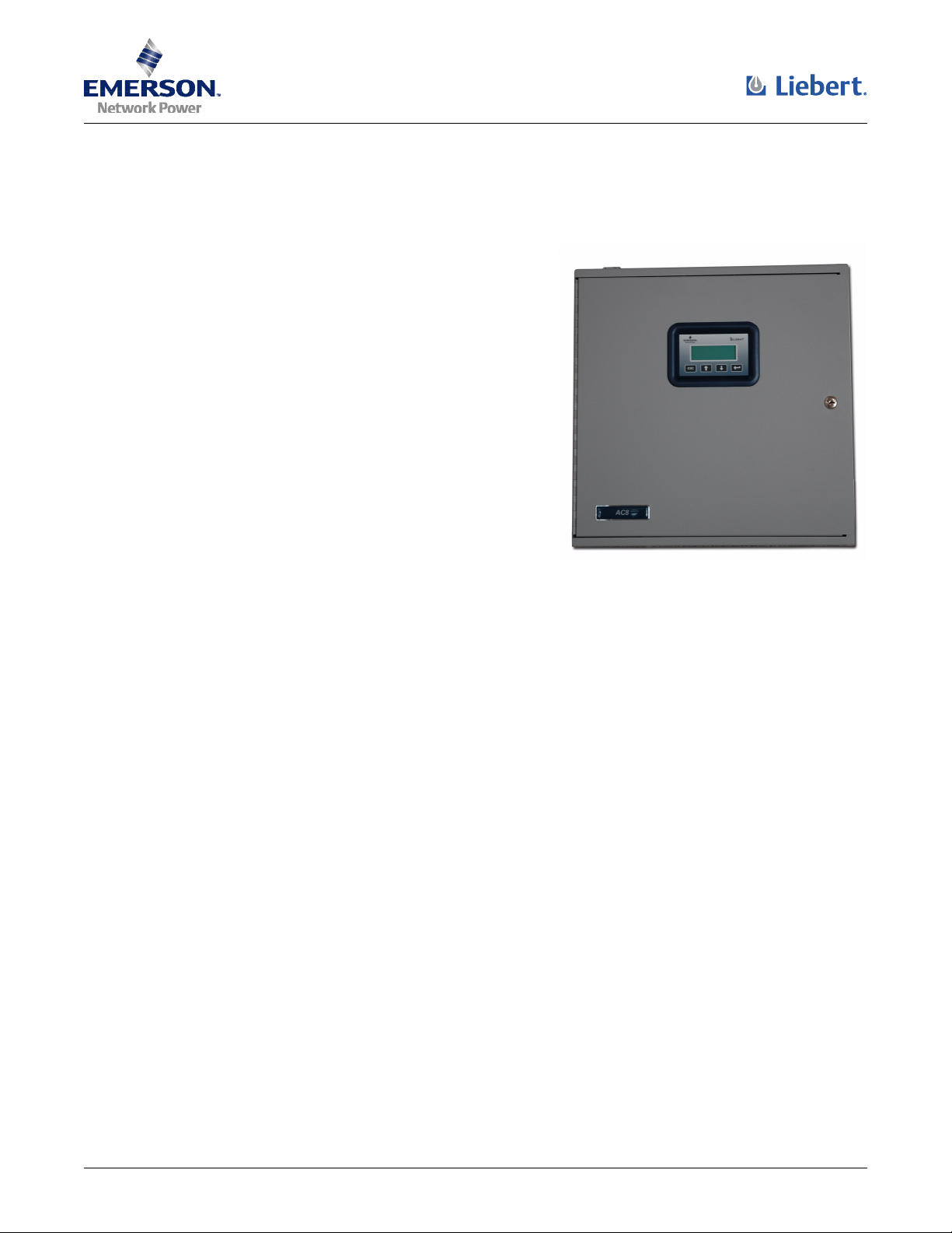
Product Specification/Installation Sheet
Description
The Liebert AC8 is ideal for coordinated control of systems
with redundant equipment, such as multiple environmental
units or pumps. When the AC8 controller detects an alarm in
an operating device, the AC8 enables a standby device and
controls the device in alarm as configured, either leaving that
device operating or disabling it.
The AC8 controller can also balance usage of devices by
rotating units through Operating and Standby modes
according to a user-defined schedule. This helps keep
redundant equipment operating efficiently and only when
needed. The AC8 can perform routine testing of standby
devices and alert personnel if a standby device fails an
operating test and requires attention.
The staging feature permits standby devices to be turned on
or off when a sensor detects specified levels. For example, the
AC8 might be configured to turn on a fan when the
temperature reaches 75°F, then turn on a second fan at 80°F.
When the temperature falls below 80°F, the second fan is turned off; when it drops below 75°F,
the first fan is turned off. Liebert’s TW420 Temperature Transmitter may be connected to any of
the four analog sensor inputs for staging and other functions.
Another capability of the AC8 is monitoring the status of connected devices and keeping
personnel apprised through local alarming. The AC8 employs local alarming and remote paging
services to keep personnel on-site and at remote locations apprised of the status of equipment.
The AC8 controller can interface with
anything that closes an electrical contact.
To improve process efficiency and
troubleshooting, the controller tracks data
in three types of logs: alarm, event and
trend.
The AC8 has both a local LCD interface
and a remote dial-up interface for
configuration and monitoring. Liebert’s
SiteScan Web may also be used for
monitoring, as well as some configuration
functions.
When an alarm condition arises, the AC8
displays alarm information, sounds an
audible alarm, changes the state of the
common alarm relay and turns connected
devices on or off according to user
configuration. If configured, the controller
also sends pager notifications.
Features and Benefits
• Custom configuration for specific applications
• Paging capability—up to four pager numbers
• Preconfigured on-board modem
• Alarm, Event and Trend logs with time and
date stamp
• Battery backup to ensure alarm notification
• Backup and download configuration files
• User interface via RS232 or modem connection
• On-board audible alarm
• Configuration data permanently stored in nonvolatile Electrically Erasable Programmable
Read Only Memory (EEPROM) for protection
against power loss
• Real-time clock
For other applications, contact your local
Liebert representative or call
1-800-222-5877.
• Status LEDs for verification and diagnostics
1
Page 2
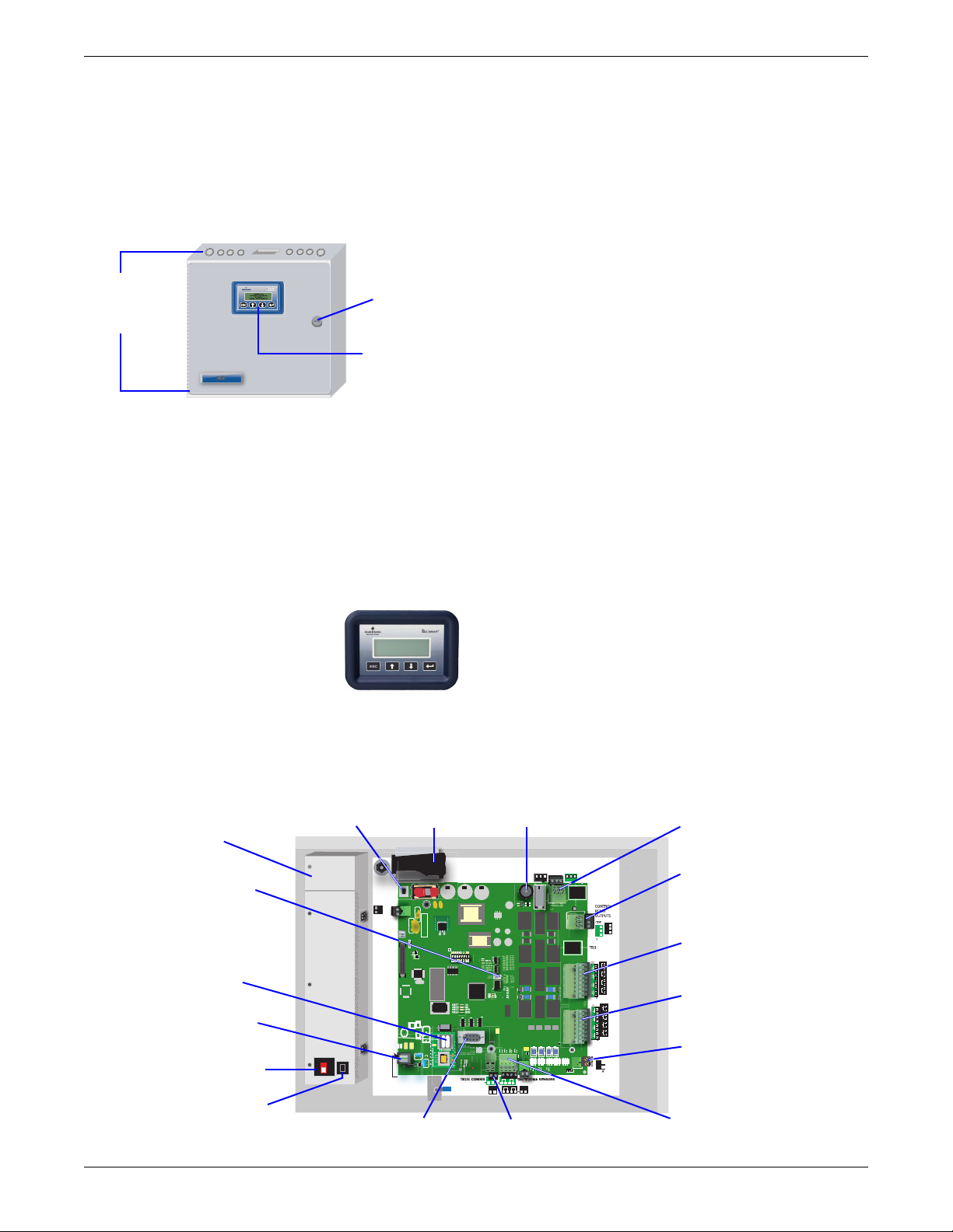
Hardware and Components
BAR CODE
Enclosure
The AC8 comes standard in an enclosure, which
features a key lock for added security. The enclosure
is made of metal to accommodate secure conduit
fittings and protect components against
environmental debris.
AC8 enclosure - External features
Knockouts and
access slots
on top and
bottom
• The enclosure is designed for easy wire routing
and terminations. Access slots for communication
cables and network wires are located on both the
top and bottom of the enclosure.
• The enclosure is 2-3/4" deep, allowing for recess
mounting in a wall. The enclosure may also be
flush-mounted.
• The enclosure houses the controller board and
Transformer Module.
Keypad Display
The keypad is a user interface
mounted on the enclosure door of
the AC8. The liquid crystal display
(LCD) provides for complete
monitoring and configuration of the
panel and is password-protected.
The keypad display provides the ability for the AC8
to operate as a complete standalone panel.
Key
lock
LCD for
configuration
and operation
Keypad
Controller Board
The controller board supports these connections:
• Eight devices, with 1 digital input and 1 digital
output per device
• Up to four zones, with staging for each zone
• Four 4-20mA analog inputs (one sensor per zone)
• Two programmable digital relay outputs
• Two Common Alarm outputs
•One EPOP input
The digital inputs are dry contacts. The analog
inputs are 4-20mA inputs. The digital outputs,
programmable relay outputs and Common Alarm
outputs are Form C contact relays. The Common
Alarm output is one output with two sets of contacts.
The point terminations are made using removable
terminal blocks. This allows for easier access to the
terminators, streamlining the process of connecting
external devices to the AC8.
The controller board is a microprocessor-based
platform for program execution. The firmware may
be easily upgraded at the job site, simplifying the
process of installing new firmware as it becomes
available. Configuration data is stored in nonvolatile
EEPROM to protect against power loss.
An RS232 operator terminal port is included with
each controller board for operator devices such as a
simple CRT terminal or laptop PC.
An integrated on-board modem allows remote access
to the AC8. The modem is factory-configured,
eliminating field configuration and wiring
requirements. An RJ11 phone modem jack is also
included.
An IGM422 connection permits access to Liebert’s
SiteScan Web Enterprise Monitoring System. This
connection allows information and alarms to be
monitored from a centrally located command center.
Transf ormer
Module
Manual Override
Switch (outputs)
Power On/Off
switch
Power receptacle
Power On/Off switch
Modem
Phone line
connector
AC8 Components and Key Features
Battery pack
TB7:
START
24V INPUT
ON
Serial interface
connector (RS232 / EIA574)
P23:
BATTERY
BATTERY
J11: PHONE
PIN 3-TIP
PIN 4-RING
BAR CODE
LIEBERT
LCD
CONTRAST
TP1
VBATT
GND
ON
ON
S2
2345678
1
OFF
MODEM
MODEM
DIP
2
Audible horn
TB5: COMMON ALARM
NO C NC
LS1
+
ENABLE
P11
AUDIBLE
Q11
OUTPUT1
DS56
OUTPUT2
DS54
OUTPUT3
DS63
OUTPUT4
DS61
OUTPUT5
DS60
OUTPUT6
DS62
OUTPUT7
DS55
OUTPUT8
DS57
CTRLLOCK
DS59
DS83
SENLOCK
DS58
CAN TX
CMN ALR
DS84
DS53
CAN RX
MOP
F PROG
574 TX
574 RX
485 RX
485 TX
INPUT1
INPUT2
INPUT3
INPUT4
DS70
INPUT5
DS67
INPUT6
DS66
INPUT7
DS65
INPUT8
DS64
R334
C71
1-2 TOP
3-4 BOTTOM
485
(TOP)
—
——
+
+ +
AG
422
TB9: ANALOG
—
+—+
(BOTTOM)
GROUND
—
+
SiteScan Web
connector (EIA422)
RELAY OUTPUTS
(TOP)
NO C NC
BOTTOM
TOP
PFM5 PFM2
TB1
EPOP INPUT
EPOP
P19
EPOP
DIS EN
TB1, TB2 INPUTS:
DRY CONTACTS ONLY.
TB3, TB4, TB5
OUTPUT RELAY
RATINGS: 24V, 3A
CLASS 2 ONLY.
RELAY
OUTPUTS
(TOP)
4
3
2
1
(TOP)
REV
4
3
2
1
TB2:
CONTACT
ASS
INPUTS
TB1: EPOP
CONTACT
INPUT
Common Alarm
connectors
Control relay
outputs
TB4:
(BOTTOM)
NC
NC
C
C
NO
NO
2
(BOTTOM)
8
7
6
5
(BOTTOM)
8
7
6
5
Digital output
connectors
Digital input
connectors
EPOP contact
input
Analog input
connectors
Page 3

Dimensions - Enclosure and Transformer Modules
ENCLOSURE TRANSFORMER MODULES (115V & 230V)
Front
view
Top/bottom
view
18"
(457.2mm)
18"
(457.2mm)
2.85"
(72.39mm)
Front
view
Top/bottom
view
14"
(355.6mm)
2.65"
(67.3mm)
3.83"
(97.2mm)
Wiring Specifications
Connection Supported Wire Type Maximum Wire Length Rating
Digital
Input/
EPOP
Digital
Output/
Control
Relay
Analog Input
2-Wire
Transducer
Analog Input
4-Wire
Transducer
Common
Alarm
Output
Communication
RS232
Communication
EIA422
SiteScan
Communication
EIA485
Phone/Modem
Line
24VAC Power
Connection
(TB7)
Power Connections (Transformer Module)
115VAC
230VAC
* Recommended
18-22 AWG Stranded & Unshielded
18 AWG* (recommended)
Non Plenum - Belden 9740
Plenum - Belden 89740
18-22 AWG Stranded & Unshielded
18 AWG* (recommended)
Non Plenum - Belden 9740
Plenum - Belden 89740
18-22 AWG Stranded & Unshielded
18 AWG* (recommended)
Non Plenum - Belden 9740
Plenum - Belden 89740
18-22 AWG Stranded & Unshielded
18 AWG* (recommended)
Non Plenum - Belden 8489
Plenum - Belden 88489
18-22 AWG Stranded & Unshielded
18 AWG* (recommended)
Non Plenum - Belden 9740
Plenum - Belden 89740
Null Modem Cable 50 ft. (15m) N/A
18-22 AWG Stranded & Shielded
22 AWG* (recommended)
Non Plenum - Belden 9461
Plenum - Belden 88761
18-22 AWG Stranded & Shielded
22 AWG* (recommended)
Non Plenum - Belden 9461
Plenum - Belden 88761
4 Wire (Pins 3 & 4)
RJ11 Connector
18-22 AWG Stranded & Shielded
18 AWG* (recommended)
Non Plenum - Belden 8770
Plenum - Belden 88770
14 AWG Stranded & Unshielded
Non Plenum - Belden 5101UE
14 AWG Stranded & Unshielded
Non Plenum - Belden 5101UE
18 AWG*
(recommended)
@3A 50 ft. (15m)
@2A 100 ft. (30m)
@1A 200 ft. (60m)
18 AWG*
(recommended)
@3A 50 ft. (15m)
@2A 100 ft. (30m)
@1A 200 ft. (60m)
750 ft. (225m)
20 AWG 22 AWG
@3A 40 ft. (12m)
@2A 60 ft. (18m)
@1A 100 ft. (30m)
750 ft. (225m)
750 ft. (225m)
20 AWG 22 AWG
@3A 40 ft. (12m)
@2A 60 ft. (18m)
@1A 100 ft. (30m)
1000 ft. (300m) N/A
3000 ft. (900m) N/A
N/A N/A
150 ft. (45m)
150 ft. (45m)
150 ft. (45m)
@3A 25 ft. (7m)
@2A 35 ft. (10m)
@1A 75 ft. (23m)
@3A 25 ft. (7m)
@2A 35 ft. (10m)
@1A 75 ft. (23m)
4-20 mA Signal
Input Selectable
Power Source
4-20 mA Signal
Input Selectable
Power Source
Dry Contact
(24VDC,
10 mA)
24VAC@3A
(12/24VDC)
(12/24VDC)
24VAC
@3A
24VAC
@1.3A
115VAC
@4A
230VAC
@0.5A
3
Page 4

AC8 Specifications
Power
Requirements
Dimensions: W x D x H, in. (mm) 18 x 2-3/4 x 18 (457.2 x 69.85 x 457.2)
Weight (Assembled) 20.56 lb. (9.33 kg)
Enclosure Type NEMA 1
Liquid Crystal Display (LCD) Four line, 20 character, backlit
Mounting Surface Building Wall or Structural Member
Ambient Operating Environment 32ºF to 104ºF (0ºC to 40ºC) 0% RH to 95% RH (non-condensing)
Processor Specifics
Model Motorola XC68HC812A4
Clock speed 16MHz
Total RAM 256Kb
Total FLASH 4M
Total EEPROM 4K
A/D Resolution (Analog IN) 12 Bit
Modem Type Embedded 14.4K bps
Clock Type Real-Time Clock
Clock battery backup type Lithium Cell (non-replaceable)
Clock battery life 7 years, constant, no power
Modem battery backup type Nickel Cadmium (replaceable)
Modem battery life 10 minutes at full load
Communications
Local Communications RS232
Remote: Modem (9600-N-8-1)
Remote: Supported pagers
SiteScan Web IGM Protocol, EIA422
Agency Listings
UL UL1012 UL1585
CSA C22.2 No. 66 and C22.2 No. 107.1
CE Yes
FCC Compliance N/A
Inputs & Outputs (Quantity)
Digital Inputs (8) Dry Contact Closure 24VDC, 10 mA
Analog Inputs (4) 4-20 mA signal input with selectable power source of 12VDC or 24VDC
Digital Outputs (8) 24VAC, 3A
Common Alarm Outputs (2) 24VAC, 3A
115VAC Transformer Module / UML11500 230VAC Transformer Module / UML23000
115VAC ±10% of nominal; 60Hz, 4A, 460VA 230VAC ±10% of nominal; 50Hz, 0.5A, 115VA
Baud rate 9600 bps, Parity=None, Data bits=8, Stop bits=1
9600 E-7-1 supports TAPI protocol version 1.8
115VAC Transformer Module (TM115) 230VAC Transformer Module (TM230)
Ordering Information
Quantity Part # Description
AC8L115
AC8L230 AC8 controller board & Transformer Module 230VAC with two 24VAC outputs (40VA each) in enclosure
201258P1 RS232 configuration cable
TW420 Temperature Transmitter Wall 4-20 mA @ 45°F to 96°F
© 2005 Liebert Corporation
All rights reserved throughout the world. Specifications subject
to change without notice.
AC8 controller board & Transformer Module 115VAC with two 24VAC outputs (40VA each) and 115VAC
receptacle in enclosure
Liebert Corporation
1050 Dearborn Drive
P.O. Box 29186
Columbus, OH 43229
Telephone: 1-800-877-9222
Facsimile: 1-614-841-6022
www.liebert.com
® Liebert and the Liebert logo are registered trademarks of
Liebert Corporation. All names referred to are trademarks or
registered trademarks of their respective owners.
SL-31101 (12/05) Rev. 0
4
 Loading...