

Page 1
DISCONTINUED
PRODUCT
OPERATOR’S
MANUAL
POWER PROTECTION
Series 300
Three Phase
Uninterruptible
Power System
WARNING
READ BEFORE
HANDLING
OR INSTALLING.
ONLY QUALIFIED
PERSONNEL
SHOULD HANDLE
THIS EQUIPMENT.
Load Bus
Synchronization
Option
Page 2

Table of Contents
Section 1 Introduction
1.0 System Description ................................................................................................ 1
Section 2 Theory of Operation
2.1 General Description................................................................................................ 2
2.2 Load Bus Sync Controller ..................................................................................... 2
2.3 Series 300 LBS Module Interface .......................................................................... 2
2.4 System Operation .................................................................................................. 3
Section 3 Operation
3.1 Operator Controls .................................................................................................. 4
3.2 Operator Procedures .............................................................................................. 5
Series 300 Load Bus Synchronization
DISCONTINUED
PRODU CT
Page 3
SECTION 1 INTRODUCTION
1.0 SYSTEM DESCRIPTION
The Liebert Load Bus Sync™ (LBS) option keeps the output of two independent Uninterruptible
Power Systems (UPSs) in sync, even when the two UPSs are operating from two different power
sources. Any UPS will typically sync to its own bypass source. As long as both UPSs are tied to the
same input and bypass sources, they will automatically stay in sync. However, if the UPSs are
operating on batteries, or different backup generators, or asynchronous bypass sources, their outputs
will tend to drift out of sync.
Maintaining sync is critically important for installations with dual power distribution systems. These
sites typically feature Liebert Precision Power Centers (PPC) with Liebert Static Bus Transfer
Switches. Each PPC has dual inputs: it can receive power from either UPS, and switch seamlessly
between the two as long as the UPS outputs are held in close synchronization. This provides
redundancy down to the PPC level. It also permits one entire half of the distribution system (upstream
of the PPC) to be taken offline for maintenance or repairs.
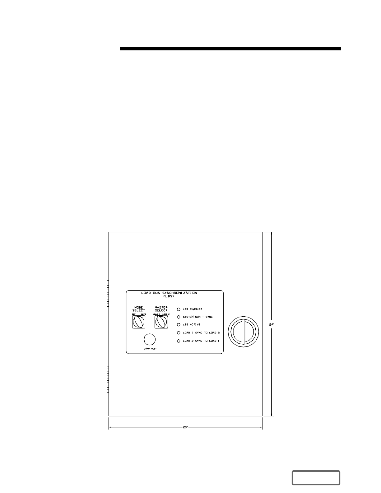
The Load Bus Sync option consists of an LBS interface in each UPS module plus one LBS controller
enclosure installed between the UPSs.
Figure 1. LBS Controller Enclosure
Series 300 Load Bus Synchronization 1
DISCONTINUED
PRODU CT
Page 4

SECTION 2 THEORY OF OPERATION
2.1 GENERAL DESCRIPTION
The Liebert Series 300 Load Bus Sync (LBS) option works by monitoring the sync reference signals of
two UPS modules, each equipped with a specially designed interface. The LBS remains dormant until
the outputs of the UPS modules drift more than a predetermined amount out of sync. In the event of an
out of sync condition, the LBS becomes active and brings the output of both UPS modules back in
sync, and then resumes the dormant state.
2.2 LOAD BUS SYNC CONTROLLER
The Series 300 LBS controller fits into a compact 20x24 inch enclosure. The front panel controls are
simple and fault tolerant. They enable the operator to do the following:
A. Select whether the controller will function automatically or be “Off.”
B. Select which UPS, (System 1 or System 2) will become the Designated Master System
(DMS). The other UPS module will become the Designated Slave System (DSS).
2.3 SERIES 300 LBS MODULE INTERFACE
In order for the LBS controller to send and receive signals from the Series 300 modules, each module
must have the proper interface installed. The Series 300 interface consists of two main components as
follows:
A. The LBS Interface Panel
B. The LBS Adapter PWA
The LBS Interface Panel has many configurations to accommodate the many input and output voltages
available on the Series 300 UPS. The LBS Adapter PWA has only one configuration, which is used with
all Series 300 LBS installations.
The LBS Interface Panel performs the following functions:
A. Receives and scales sync signals from the LBS Controller.
B. Receives signals from the LBS Controller to determine whether to use internal sync or
sync to the other UPS module.
C. Receives static switch disable signals from the LBS Controller.
D. Provides the LBS Controller with bypass voltage signals, output voltage signals and
bypass available signals.
E. Provides the LBS Controller with 120 VAC control power.
The LBS Adapter PWA performs the following functions:
A. Receives and shapes sync signals for the LBS Interface Panel and routes the sync signal
to the processor board.
B. Selects the sync source, either internal or from the other UPS based on signals that
originate with the LBS Controller and passed on through the LBS Interface Panel.
C. Disables the static switch on the slave UPS when the slave UPS is acquiring sync with the
master UPS.
Series 300 Load Bus Synchronization 2
DISCONTINUED
PRODU CT
Page 5

D. Operates the flashing warning light on the front panel of the slave UPS indicating that the
Main Rotary Switch should not be operated while sync is being acquired with the master
UPS.
2.4 SYSTEM OPERATION
The Series 300 LBS option performs the following functions:
A. Continuously senses the phase relationship between the outputs of the two UPS modules
that make up the system.
B. If the two systems lose sync with each other for more than a predetermined period of time
(adjustable from 0.1 to 5 seconds) and the AUTO/OFF switch is set to the AUTO position
then the LBS will sync the Designated Slave System (DSS) to the Designated Master
System (DMS). The DMS and DSS are selected manually using the master system select
switch. If the DSS is on bypass and unable to sync to the DMS then the DMS will sync to
the output bus of the DSS. This reselection of the master system will be accomplished
automatically.
C. Continuously monitors the sync and the quality of the bypass input voltage to both
systems. Once the sync and voltage quality between to two systems have been restored
for 5 seconds, the LBS will become dormant and allow each system to operate
independently.
Note: Failure of any part of the LBS will not cause system failure. The worst case effect would be that
the two systems would not be able to synchronize to each other.
Series 300 Load Bus Synchronization 3
DISCONTINUED
PRODU CT
Page 6

SECTION 3 OPERATION
3.1 OPERATOR CONTROLS
Operation of the LBS has deliberately been kept as simple possible. There are only three controls and
five indicator lights on the SERIES 300 LBS Controller enclosure. Each LBS equipped UPS module has
one indicator light mounted on the bezel below the front display panel. The indicators are:
A. LBS Enabled. Indicates that the LBS circuitry is in the Automatic Mode.
B. System Non-Sync. Indicates that the DSS is no longer in sync with the DMS. This alarm
will appear during the transition from internal bypass sync to DMS sync.
C. LBS Active. Indicates that the LBS circuitry has taken over the sync of the UPS. If the
System Non-Sync indicator is also on, it means that synchronization is in progress.
D. Load 1 Sync to Load 2. Indicates that the UPS critical bus is synchronized to the bypass
input of the DMS, in this case System 2. This indicator will turn on when the sync process
is complete.
E. Load 2 Sync to Load 1. Indicates that the UPS critical bus is synchronized to the bypass
input of the DMS, in this case System 1. This indicator will turn on when the sync process
is complete.
F. Warning LBS Active. This indicator is located on the bezel below the front display panel
on each UPS module. This indicator will be flashing when the DSS is acquiring sync with
the DMS. This is a warning, not to operate the Main Rotary Switch.
Standard LBS controls are:
A. Mode Select Switch. Provides manual selection of automatic operation or “OFF” modes.
In the automatic mode the LBS will be enabled. In the “OFF” mode, both UPS modules
will synchronize independently.
B. Master Select Switch. Provides manual selection of the DMS source. The LBS circuitry
will automatically switch DMS sources should the initially selected DMS lose bypass
input.
C. Lamp Test. Push this button to test the indicators lights on the LBS Controller. There is
no lamp test for the warning indicators on the UPS modules.
3.2 OPERATOR PROCEDURES
The only two operator controls are the Mode Select Switch and the Master Select Switch. The Mode
Select Switch can be left in the Automatic position all the time. The OFF position can be selected at
times when it is desirable to allow the UPS systems to synchronize independently.
The Master Select Switch allows the operator to chose which UPS bypass source will provide the
reference sync signal.
In normal operation, both System 1 and System 2 will be functioning and the LBS Mode Select Switch
will be in the Automatic position. The LBS enable indicator and one of the Load X Sync to Load Y
indicators will be illuminated. If the two UPS systems drift out of sync (while on battery for example),
the LBS Active and System Non Sync indicators will be illuminated. The Load X Sync to Load Y
Series 300 Load Bus Synchronization 4
DISCONTINUED
PRODU CT
Page 7

indicator will be off during the synchronization process and turn back on when the process is
completed.
When the slave system is in the process of synchronizing to the master system, the Warning Indicator on
the slave system will be flashing on and off. This is to warn against operating the Main Rotary Switch.
SL-24536 (5/00)
Series 300 Load Bus Synchronization 5
PRODU CT
DISCONTINUED
 Loading...