

Page 1
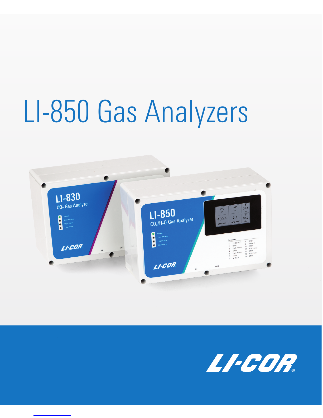
Using the LI-830 and
LI-850 Gas Analyzers
Page 2

Page 3

Using the LI-830 and LI-850
Gas Analyzers
LI-COR Biosciences
464 7 Superior Street
Lincoln , Nebraska 68504
Phone: +1-402 -467-3576
Toll free: 800-44 7-357 6 (U.S. and Canada)
[email protected]
Regional Offices
LI-COR Biosciences GmbH
Siemensstraße 25A
613 52 Bad Homburg
Germany
Phone: +49 (0) 617 2 17 17 771
[email protected]
LI-COR Biosciences UK Ltd.
St. John’s Inno vation Centre
Cowley Road
Cambridge
CB4 0WS
United Kingdom
Phone: +44 (0) 122 3 422 10 2
[email protected]
LI-COR Distributor Network:
www.licor.com/env/distributors
Page 4
Notice
The information in this document is subject to change without notice.
LI-COR MAKES NO WARRANTY OF ANY KIND WITH REGARD TO THIS MATERIAL, INCLUDING BUT NOT
LIMITED TO THE IMPLIED WARRANTIES OF MERCHANTABILITY AND FITNESS FOR A PARTICULAR PURPOSE.
LI-COR shall not be held liable for errors contained herein or for incidental or consequential damages in connection with
the furnishing, performance, or use of this material.
This document contains proprietary information, which is protected by copyright. All rights are reserved. No part of this
document may be photocopied, reproduced, or translated to another language without prior written consent of LI-COR,
Inc.
Windows® is a trademark of Microsoft, Inc. macOS® is a trademark of Apple, Inc., registered in the US and other countries. Drierite is a registered trademark of the W.A. Hammond Drierite Company. Excelon Bev-a-line is a registered trademark of Thermoplastic Processes, Inc. All other trademarks and registered trademarks are property of their respective
owners.
Printing History
© Copyright 2018, LI-COR, Inc. All rights reserved.
Publication Number: 984-17190
Created on Tuesday, September 4, 2018
Notes on Safety
This LI-COR product has been designed to be safe when operated in the manner described in this manual. The safety of
this product cannot be guaranteed if the product is used in any other way than is specified in this manual. The product is
intended to be used by qualified personnel. Read this entire manual before using the product.
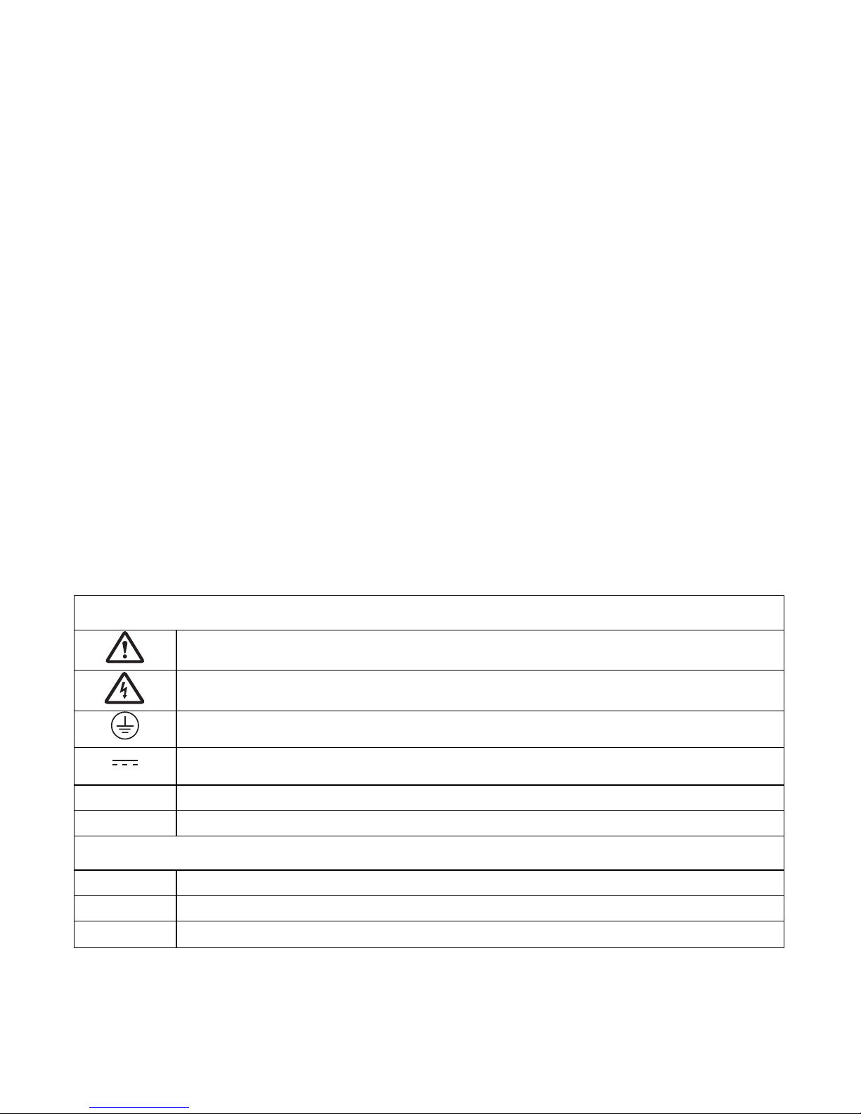
Equipment markings:
The product is marked with this symbol when it is necessary for you to refer to the manual or
accompanying documents in order to protect against injury or damage to the product.
The product is marked with this symbol when a hazardous voltage may be present.
The product is marked with this symbol if a Chassis Ground connection is required.
The product is marked with this symbol to indicate that a direct current (DC) power supply is
required.
WARNING
Warnings must be followed carefully to avoid bodily injury.
CAUTION
Cautions must be observed to avoid damage to your equipment.
Manual markings:
Warning
Warnings must be followed carefully to avoid bodily injury.
Caution
Cautions must be observed to avoid damage to your equipment.
Note
Notes contain important information and useful tips on the operation of your equipment.
ii
Page 5

iii
CE Marking:
This product is a CE-marked product. For conformity information, contact LI-COR Support at [email protected].
Outside of the U.S., contact your local sales office or distributor.
California Proposition 65 Warning
WARNING: This product contains chemicals known to the State of California to cause cancer and birth defects or other
reproductive harm.
Federal Communications Commission Radio Interference Statement
WARNING: This equipment generates, uses, and can radiate radio frequency energy and if not installed in accordance
with the instruction manual, may cause interference to radio communications. It has been tested and found to comply
with the limits for a Class A computing device pursuant to Subpart J of Part 15 of FCC rules, which are designed to
provide a reasonable protection against such interference when operated in a commercial environment. Operation of this
equipment in a residential area is likely to cause interference in which case the user, at his own expense, will be required
to take whatever measures may be required to correct the interference.
Waste Electronic and Electrical Equipment (WEEE) Notice
This symbol indicates that the product is to be collected separately from unsorted municipal waste. The following applies to users in European countries: This product is designated for separate collection at an
appropriate collection point. Do not dispose of as household waste. For more information, contact your
local distributor or the local authorities in charge of waste management.
Page 6

iv
Page 7

v
Contents
Section 1. General description
Online resources 1-1
Application software 1-1
Integrator's guide 1-1
Instruction manual 1-1
What's what 1-2
Gas analyzer 1-2
Accessories kit 1-3
Air pump (optional) 1-3
Display (optional) 1-3
Connecting with the analyzer 1-4
The terminal strip 1-6
Powering the LI-830 and LI-850 1-7
Using the universal power adapter 1-7
Using the terminal strip power connectors 1-7
Installing device drivers 1-8
Storing the gas analyzer 1-8
Section 2. Configuring the gas analyzer
Overview of the software 2-1
Configuring graphs 2-2
Logging data to a PC 2-3
Instrument settings 2-4
Configuring the DAC outputs 2-4
Optimizing the DAC resolution 2-4
Computing readings from the DAC output 2-5
Other options 2-7
Using alarms 2-8
Using the Pump 2-10
Section 3. Troubleshooting
Instrument will not power on 3-1
Unable to span or zero the instrument 3-1
Instrument reports -50 ppm CO2 or measurements jump around 3-2
Page 8

Section 4. Maintenance
User calibration 4-1
Setting the CO2 zero 4-1
Setting the primary CO2 span 4-2
Setting the secondary CO2 span 4-3
Setting the H2O zero and spans (LI-850 only) 4-3
Recovering from a bad zero or span 4-3
Cleaning the optical bench 4-4
Replacing a fuse 4-6
Appendix A. Equation Summary
Appendix B. Specifications
Appendix C. Warranty
vi
Page 9

Section 1.
General description
This section introduces the LI-830 CO2analyzer and LI-850 CO2/H2O analyzer.
The LI-830 and LI-850 both measure CO2in air at concentrations from 0 to 20,000
ppm. The instruments differ in that the LI-850 measures water vapor in air as well,
and the LI-830 does not. As a consequence of the water vapor measurement, the
LI-850 is able to measure CO2concentrations with greater accuracy. Regardless of
this difference, operating both instruments is essentially the same.
Online resources
In addition to the contents of your box, you may be interested in the following
resources. All are available from www.licor.com/env/support. Select the LI-830 and
LI-850 Analyzer.
Application software
Required to configure the instrument through a graphical interface, the software is
available for both Windows®and macOS®operating systems. The software is used
to configure the instrument, read measurements, and configure data logging to a
computer. For Windows®7 and 8, the device drivers must be installed manually
before you can connect with the instrument.
Integrator's guide
The Integrator's Guide describes how to control the instrument using a terminal
program and read data in a command-line interface.
Instruction manual
A .pdf version of this document can be downloaded to your computer.
1-1Using the LI-830 and LI-850 Gas Analyzers
Page 10
Section 1. General description
What's what
The LI-830 and LI-850 include a core set of components and each may include
optional components. These are described below.
Gas analyzer
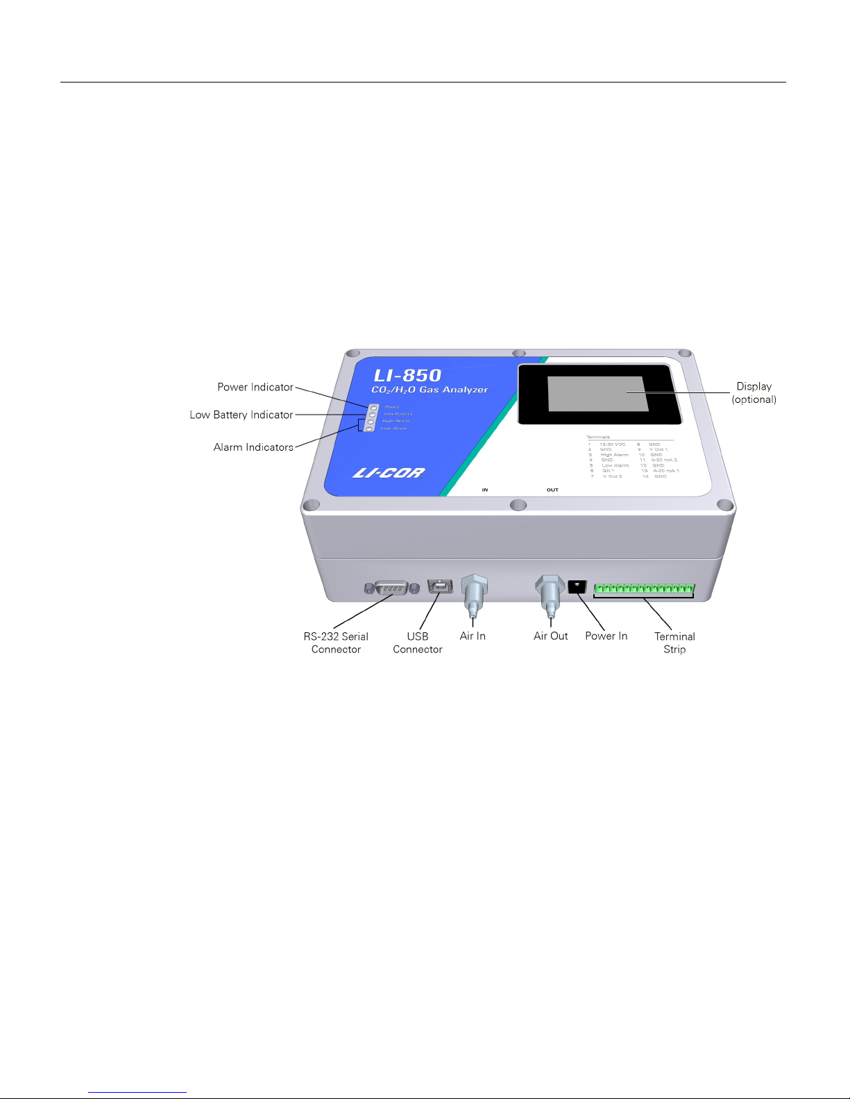
This is the gas analyzer in an enclosure. It may include an optional built-in pump
and display.
l Power indicator: Illuminates when the instrument is powered on.
l Low Battery indicator: Illuminates if the power supply voltage drops below 10.5
volts. The instrument will continue to operate with a low battery, but expect a
corresponding decline in performance.
l Alarm indicators illuminate if an alarm threshold has been crossed. See Using
alarms on page2-8.
l RS-232 Serial and USB connectors to connect with a computer or serial device.
l Air Inlet and Air Outlets are shipped with covers in place. Keep the covers so you
can put them back over the ports when the analyzer is not in use.
l Power In: Compatible with 12 to 30 VDC power supplies.
l The Terminal Strip has another power connector and outputs for alarms and
digital-to-analog converters (DAC).
1-2 Using the LI-830 and LI-850 Gas Analyzers
Page 11

Accessories kit
Accessories kit: Part
Number 9980-065
The instrument includes a standard accessories kit, which has accessories and some
replacement parts for your gas analyzer. The accessories kit includes the following
components:
Description Quantity Part Number
Universal power supply; Input: 100 to 240 VAC, 50 to 60 Hz;
Output: 12 VDC, 2.5 amps
1 591-13032
Outlet adapter kit for universal power supply 1 591-13033
USB cable; Standard 1.8 m USB-A to USB-B
a
1 392-06652
RS-232 null modem, cross-over cable kit
a
1 9975-016
14-pin terminal block; Includes label sticker (250-05340) 1 331-05273
Tube fitting nuts for air inlet and outlet 2 9861-036
Bev-a-line IV plastic tubing; 3.6 meter roll 1 222-01824
Air filters 2 9967-008
Quick-connect straight unions 2 300-03123
Cleaning kit 1 9980-066
3" Source and detector cleaning swabs 5 610-05314
5" Optical path cleaning swabs 5 610-05315
O-Rings (AS-018 Nitrile 70) 4 192-00226
Black polyurethane feet 4 234-02268
Air pump (optional)
An optional air pump is available for the gas analyzer. The pump (if applicable) is
installed in the gas analyzer case. If you want to add a pump, you can order one
later.
Display (optional)
An optional display is available. The display shows CO2concentration, H2O concentration (LI-850 only), bench temperature, and pressure.
a
The use of cables other than those provided may result in improper electrical performance.
Section 1. General description
1-3Accessories kit
Page 12
Section 1. General description
Connecting with the analyzer
The following tutorial describes the basic steps you'll follow when you turn on the
LI-830 or LI-850 for the first time.
1 Install the software on your computer
The software is used to configure data communication, analog and digital outputs,
alarms, data logging, and to verify the calibration.
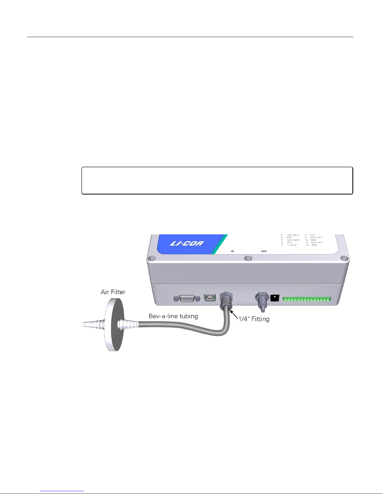
2 Install an air filter on the air-in port
Caution: Always install an air filter on the input air before operating the LI-830
or LI-850. Failure to use a filter will cause contamination of the optical bench.
Retrieve an air filter and tubing from the accessories kit. Cut a 5 to 10 cm piece of
tubing. Attach the filter and tubing to the air-in port. Observe the arrow on the filter and be sure that the air flow is in the proper direction.
3 Install the USB cable
The USBconnection is the simplest way to connect the analyzer with a computer.
If you want to use the RS-232 serial connection instead, connect the cable to the
serial port, and install a serial-to-USB adapter on the serial cable, if needed.
1-4 Using the LI-830 and LI-850 Gas Analyzers
Page 13
4 Power on the gas analyzer
The LI-830 and LI-850 will turn on when power is supplied, so plug in the power
cable to turn it on. If you use an alternative power supply, it must be able to source
a minimum of 1.2 A at 12 VDC while the instrument warms up. After the warmup, the instrument will draw about 0.3 A at 12 VDC.
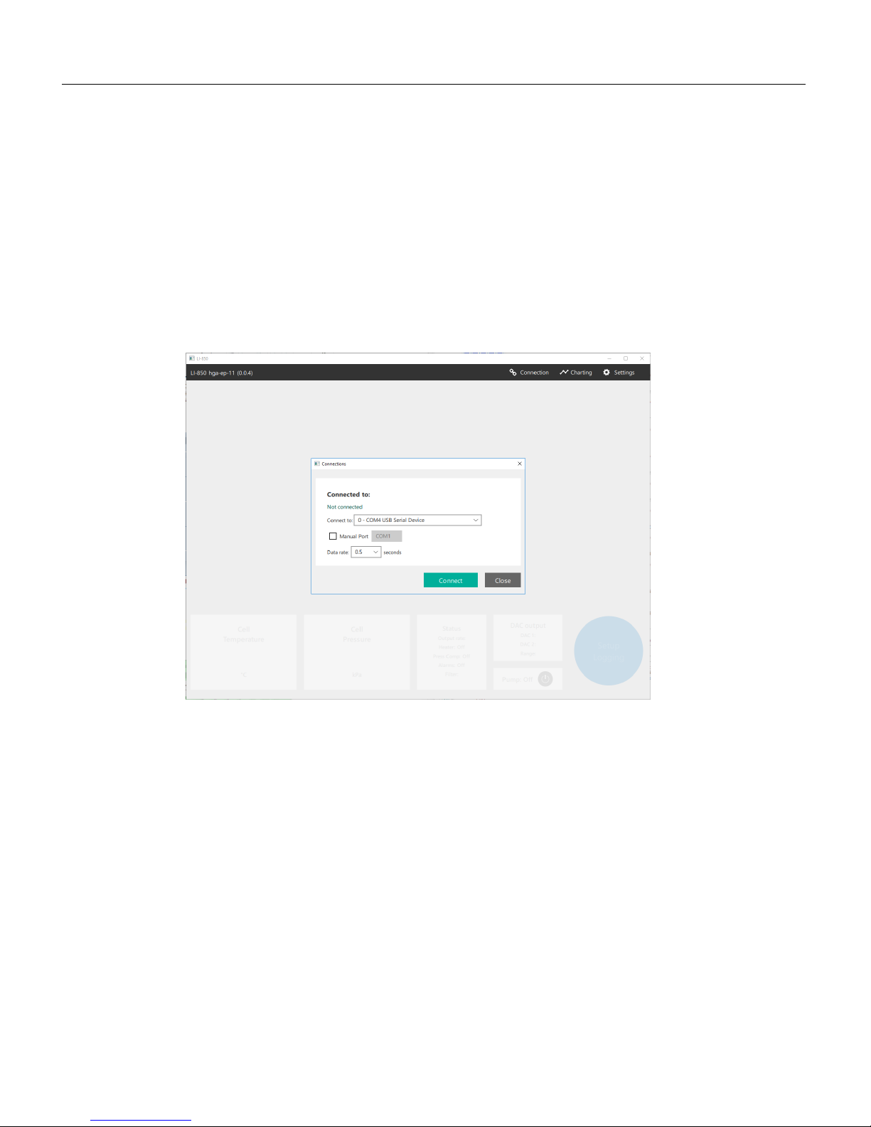
5 Connect with the gas analyzer
Start the software.
Click the Connection button in the upper right of the display. Select your instru-
ment from the list, set the data rate, then click Connect. Data will populate the win-
dow after connecting. You can enter the COM port manually by checking Manual
Port and setting the port number (COM#).
If you are using Windows®7 or 8, install the drivers before you connect, as
described in Installing device drivers on page1-8.
Section 1. General description
1-5Connecting with the analyzer
Page 14

Section 1. General description
The terminal strip
The terminal strip connects to the front panel of the instrument. The pin assignments are given on the top of the instrument, and there is a sticker in the accessories kit that you can use to help identify which terminal is which.
Terminal Label Description
1 12-30 VDC Voltage In, 12-30 VDC
2 GND Ground
3 High Alarm High Alarm
4 GND Ground
5 Low Alarm Low Alarm
6 GND Ground
7 V OUT 2 Voltage output channel 2
8 GND Ground
9 V OUT 1 Voltage output channel 1
10 GND Ground
11 4-20 mA 2 Current output channel 2
12 GND Ground
13 4-20 mA 1 Current output channel 1
14 GND Ground
1-6 Using the LI-830 and LI-850 Gas Analyzers
Page 15
Powering the LI-830 and LI-850
A power supply—either a battery or the universal power adapter—can be connected
to the LI-830 and LI-850 power jack or to pins 1 and 2 on the terminal strip. The
instruments require 12 to 30 VDC. The power supply must be able to provide 14
watts (1.2 A at 12 V) during warmup and about 3.6 watts (0.3 A at 12 V) during
normal operation.
Using the universal power adapter
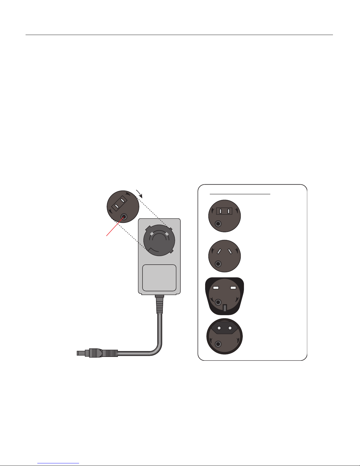
The included power supply is compatible with mains power in most localities globally (input 100 to 240 VAC, 50 to 60 Hz; output 12 VDC, 2.5 amps). You may need
to install different blades from the outlet adapter kit to fit your wall outlets.
P
U
S
H
OPEN
LOCK
N. America, Japan
United Kingdom
Australia
Europe
Turn clockwise
to lock
Push button, then
turn counterclockwise to release
Outlet Adapter Kit
P
U
S
H
OPEN
L
OCK
P
U
S
H
O
P
EN
LOCK
P
U
S
H
OPEN
LO
CK
P
U
S
H
LOCK
OPEN
Using the terminal strip power connectors
The terminal strip has connectors for any power supply that has bare leads. Pin 1 is
the positive (+) terminal, and pin 2 is the negative (-) terminal.
Section 1. General description
1-7Powering the LI-830 and LI-850
Page 16

Section 1. General description
Installing device drivers
If you are using Windows 7 and 8, you'll need to install device drivers. After connecting the LI-830 or LI-850 to your computer with the USB cable, follow these
steps:
1
Download the drivers and unzip the file.
Drivers are available at
https://www.licor.com/documents/pamrygkdwsl8c61wj6y815gnf4tukh3t
2
Press the Windows key ( ), type Device Manager, and press Enter to open your
device manager.
3
Under Other Devices, select the LI-830/850.
4
Right-click LI-830/850 and select Update Driver Software.
5
Browse and select the folder with the driver files.
6
Click Next to finish installing the drivers.
When they are installed, you should see LI-COR 8x0 under Ports (COM & LPT).
Storing the gas analyzer
When you are done using the gas analyzer, follow these practices to be sure that it
is ready to use the next time you need it. The instrument can be stored in non-condensing conditions. If the instrument is stored in high humidity or moderate
humidity for a long time while powered off, some optical components may temporarily become saturated with humidity. If this occurs, the instument may need to
run for several days before readings return to normal. When storing the instrument.
l Install the covers over the air inlet and outlet. This will keep dust, bugs, and
other contaminants out of the optical cell.
l Disconnect the power supply and power wires.
l If possible, store the instrument in an air conditioned environment.
1-8 Using the LI-830 and LI-850 Gas Analyzers
Page 17
Section 2.
Configuring the gas analyzer
This section describes the basic operating procedures for the LI-830 and LI-850 gas
analyzers. This section depends upon the instrument software, which can be downloaded from the LI-CORtechnical support web site: www.licor.com/env/support.
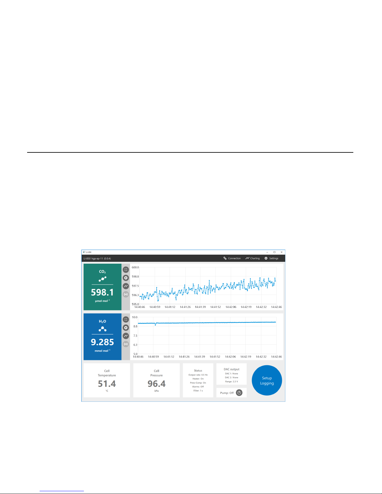
Overview of the software
After connecting, the software presents you with live data and graphs. With the
LI-830, you'll have CO2; with the LI-850, you'll have both CO2and H2O.
2-1Using the LI-830 and LI-850 Gas Analyzers
Page 18
Section 2. Configuring the gas analyzer
Configuring graphs
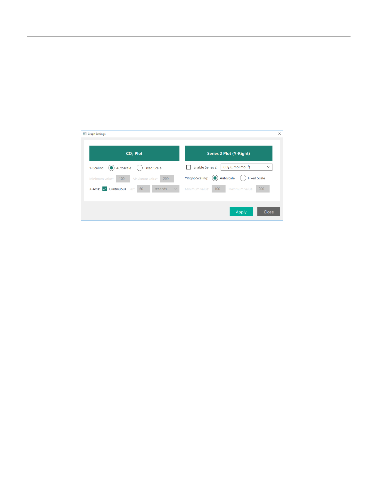
The software will always display a graph on the main page (two with the LI-850),
and you can configure the graphs by clicking the Charting button or any of the
Chart Settings buttons beside a particular chart. The options available are the same,
regardless of how you get to them.
The graphs display a fixed variable: CO2and H2O with the LI-850. You can configure the settings for each graph and add a second variable. The options are:
Y-Scaling: Choose Autoscale or Fixed Scale. With Fixed Scale, you can set the min-
imum and maximum value for each variable displayed.
X-Axis: With Continuous checked, the graph will display all of the data from the
time you connect to the instrument, rescaling the x-axis when needed. With
Continuous cleared, the graph can be configured to display the most recent data for
a time period.
Series 2 is an option to plot a second variable on the graph with scaling on the
right axis. When checked, you can choose from CO2concentration, cell temperature, cell pressure, CO2absorption, or input voltage. With the LI-850, the H2O
concentration, H2O dewpoint, and H2O absorption will also be available.
2-2 Using the LI-830 and LI-850 Gas Analyzers
Page 19
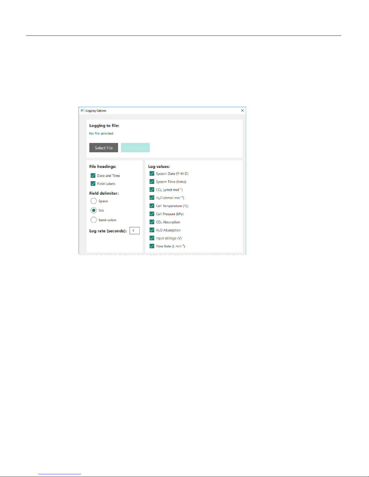
Logging data to a PC
The instrument can log data as a text file, which will be stored to the connected
computer. Configure the log file under Settings > Logging Options. To log data:
1
Create a file.
Click Select File, then choose the directory where you want to store the file, and
name the file.
2
Configure the log parameters.
l File headings: When checked, the Date and Time and Field Labels for data
columns will be included in the data file header.
l Field delimiter: Choose between a space, tab, or semi-colon delimited text file.
l Log rate (seconds): How often a value is recorded. This can be 0.5, 1, 2, 3, 4, 5,
10, or 20 measurements per second. It is independent of the Filter setting
(described in Other options on page2-7).
l Log values: Select the values you want in the log file.
3
Click Start logging.
The instrument will create a text file according to the parameters you set. You can
open the logged data in a text editor or most spreadsheet programs.
Section 2. Configuring the gas analyzer
2-3Logging data to a PC
Page 20
Section 2. Configuring the gas analyzer
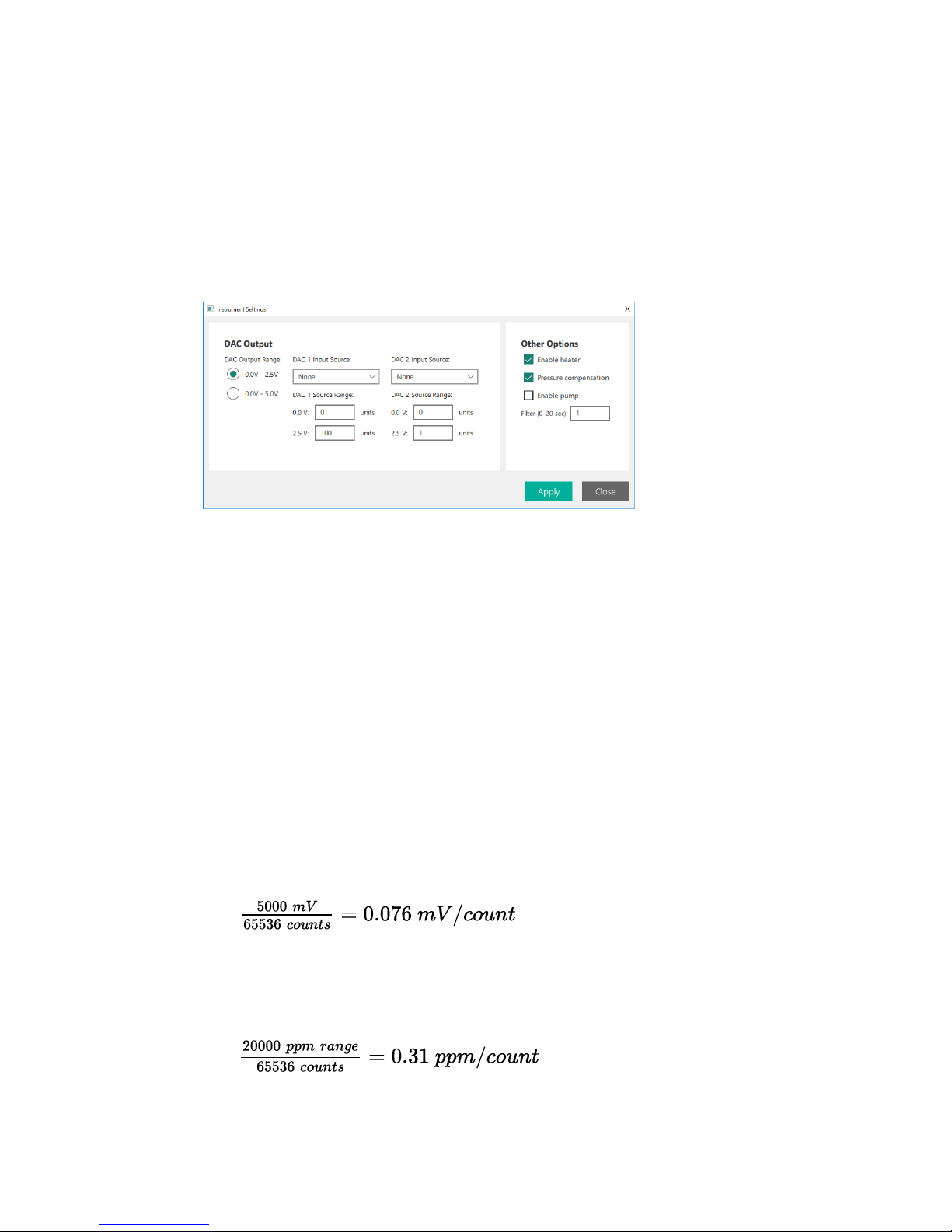
Instrument settings
Under Instrument > Settings, you'll find the DAC (digital-to-analog) Outputs (0 to
2.5 V, 0 to 5 V, and 4 to 20 mA), and Other Options, including the heater controls,
pressure compensation control, pump control, and the digital signal filter.
Configuring the DAC outputs
This section describes how to configure the voltage and current outputs. Both
voltage and current outputs are configured at the same time, in the same place:
l DAC 1 configures V Out 1 (pin 9) and 4-20 mA 1 (pin 13) on the terminal strip
l DAC 2 configures V Out 2 (pin 7) and 4-20 mA 2 (pin 11) on the terminal strip
Optimizing the DAC resolution
When configuring the analog outputs, keep in mind that the selected ppm range
will affect the resolution of data that is sent over the analog outputs.
Think of it like this:The 16-bit DACs can output a fixed number of values (65,536
to be exact). If a DAC is configured to output 0 to 5000 mV, you will have resolution of 0.076 mV per count.
2-1
With the 0 to 5 volt output range corresponding with a 0 to 20,000 ppm CO2concentration range, the finest change in concentration that can be resolved is equal to
0.31 ppm.
2-2
2-4 Using the LI-830 and LI-850 Gas Analyzers
Page 21
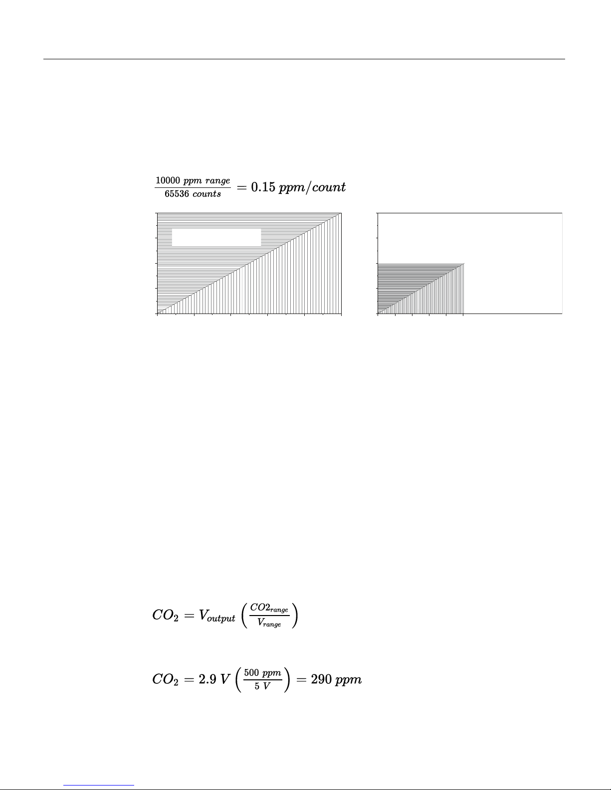
If you are measuring concentrations between 0 and 10,000 ppm, the range is
10,000 ppm. By configuring the DAC range for 0 V = 0 ppm CO2and 5 V = 10,000
ppm, the DAC output will have twice the resolution as it would in the previous
configuration.
2-3
20,000
10,000
15,000
5,000
0
0 2 3 4 51
Volts
CO Concentration (μmol mol
-1
)
20,000
10,000
15,000
5,000
0
0 2 3 4 51
Volts
CO Concentration (μmol mol
-1
)
65,536 discreet points over
the 10,000 ppm range gives 2x the resolution
65,536 discreet points over
the 20,000 ppm range
Figure 2-1. The resolution of the analog outputs depends upon the range. If the DACs are
configured to output data over the full 0 to 20,000 ppm range, the data output over the
DACs will have lower resolution (left). If the DACs are configured to output data over a
narrower range (for example, 0 to 10,000 ppm as shown on the right), the data output over
the DACs will have higher resolution.
Also keep in mind that the instrument will not output meaningful information
over the DACs if the measured value is outside of the configured output range.
Computing readings from the DAC output
Here we give some example computations.
Example 1: Computing CO2from a voltage output; 0 to 500 ppm range
The CO2concentration is calculated from the DAC output. In this example, let's
configure the output range for 0 V = 0 ppm and 5 V = 500 ppm. The concentration
is computed from:
2-4
If the output voltage is 2.9 V, then
2-5
Section 2. Configuring the gas analyzer
2-5Computing readings from the DAC output
Page 22
Section 2. Configuring the gas analyzer
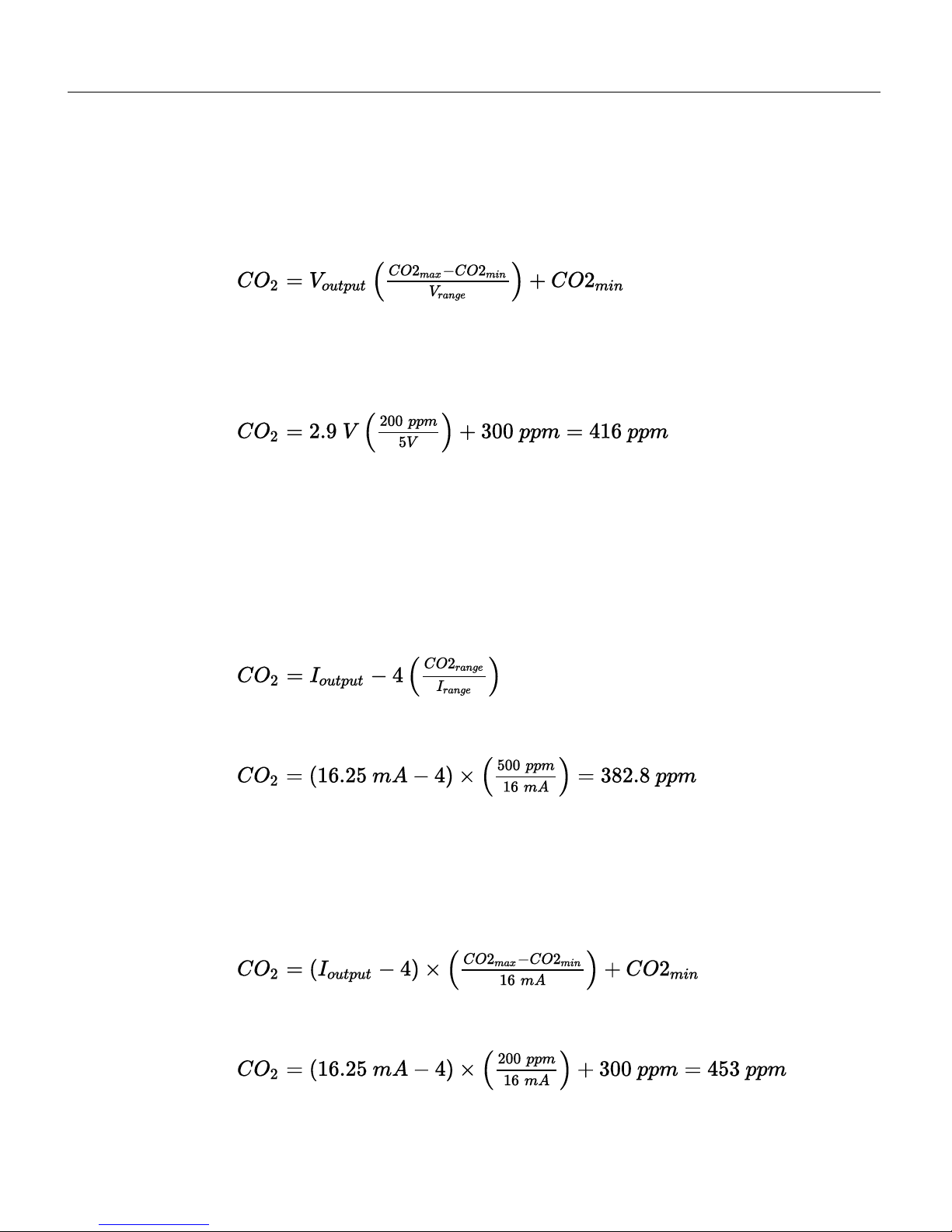
Example 2:Computing CO2from a voltage output; 300 to 500 ppm range
In this example, let's configure the output range for 0 V = 300 ppm and 5 V = 500
ppm, so the full range is 200 ppm, and notably, 0 V is no longer 0 ppm.
2-6
CO2
max
is the reading that corresponds with the high voltage output (500 ppm in
this case), and CO2
min
is the reading that corresponds with the low voltage output
(300 ppm in this case). With an output voltage of 2.9, the concentration is:
2-7
Example 3: Computing CO2from a current output; 0 to 500 ppm range
Unlike the voltage outputs, which are 0 to 2.5 or 0 to 5 V, the current outputs are
from 4 to 20 mA. Therefore, the range is always 16 (20 - 4), and the offset is always
4. Electrical current is indicated with I. In this example, let's configure the output
range for 4 mA = 0 ppm and 20 mA = 500 ppm. The concentration is computed
from:
2-8
If the current is 16.25 mA, then
2-9
Example 4: Computing CO2from a current output; 300 to 500 ppm range
In this example, let's configure the output range so that 4 mA = 300 ppm and 20
mA = 500 ppm. Now, we need an offset that corresponds with the minimum CO
2
reading (300 ppm).
2-10
If the current is 16.25 mA, then
2-11
2-6 Using the LI-830 and LI-850 Gas Analyzers
Page 23

Example 5: Computing cell temperature from a voltage output
Cell temperature (T in °C) is calculated from the DAC output with the following:
2-12
where XFis the full scale temperature value that corresponds to the high voltage,
XZis the temperature value that corresponds to the low voltage, V is the voltage
reading, and V
max
is the output range (either 2.5 V or 5 V).
Example 6: Computing cell pressure from a voltage output
Cell pressure (kPa) can be computed from a voltage output with the following:
2-13
where XFis the full scale pressure value that corresponds to the high voltage, XZis
the pressure value that corresponds to the low voltage, V is the voltage reading, and
V
max
is the output range (either 2.5 V or 5 V).
Other options
Enable heater: The heater should be enabled to maintain the optical bench temperature. Normally the optical bench will be about 51.4 °C. If you disable the
heater, the instrument will not perform as specified.
Pressure compensation: Pressure compensation should be applied to ensure that
the instrument compensates for changes in pressure. Disabling pressure compensation will lead to less accurate measurements.
Enable pump: If your instrument is equipped with a pump, this box will be interactive. Check it to turn the pump on. Clear it to turn the pump off.
Filter: The digital filter instructs the instrument to average the readings. A value of
0 means no averaging, whereas a value of 20 instructs the instrument to average
the previous 20 seconds of measurements. Increasing the averaging time will
decrease the variation in each reported value, but will also reduce the instrument
response time.
Section 2. Configuring the gas analyzer
2-7Other options
Page 24
Section 2. Configuring the gas analyzer
Using alarms
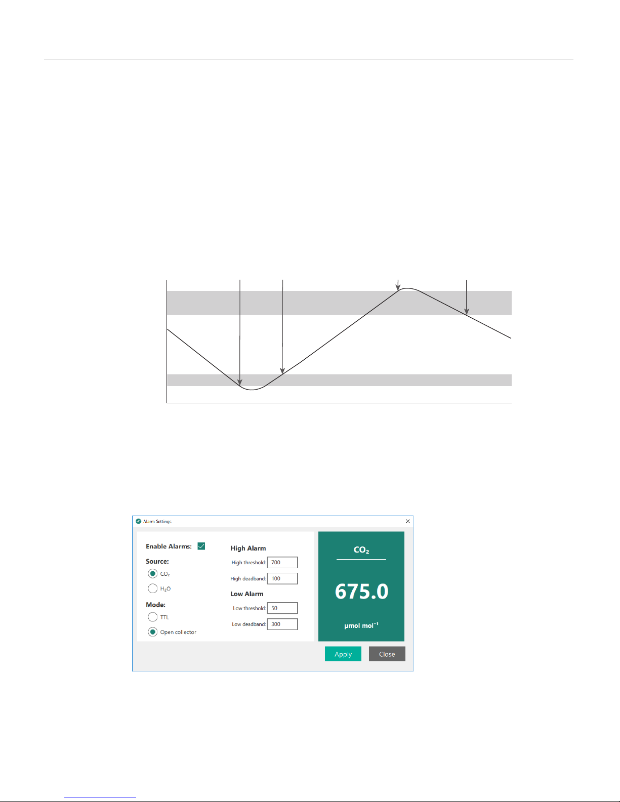
The alarms can be set for CO2or H2O (in the LI-850). In either case, each alarm
features an activation level and a deadband. The low alarm is activated if the measured concentration drops below a threshold. The deadband is the range above the
low level over which the alarm remains activated. The high alarm is activated if the
measured concentration exceeds a threshold. The deadband is the range below the
high level over which the alarm remains activated.
Elapsed Time
CO
2
Concentration, ppm
300
400
700
600
Low Deadband
High Deadband
500
Low alarm
activated when
CO2 <300 ppm
On = 300
Low alarm
deactivated when
CO2 >350 ppm
Deadband = 50
High alarm
activated when
CO2 >700 ppm
On = 700
High alarm
deactivated when
CO2 <600 ppm
Deadband = 100
Figure 2-2. An alarm is triggered when a concentration is outside of a threshold. For
example, the low alarm is activated if the concentration drops below 300 ppm and is deactivated when the concentration rises above 350 ppm. The high alarm is activated if the
CO2concentration exceeds 700 ppm. The alarm is deactivated when the concentration
drops below 600 ppm.
Figure 2-3. The Alarm Settings window is where you configure alarms. The settings shown
here will give the behavior shown in Figure 2-2 above.
2-8 Using the LI-830 and LI-850 Gas Analyzers
Page 25
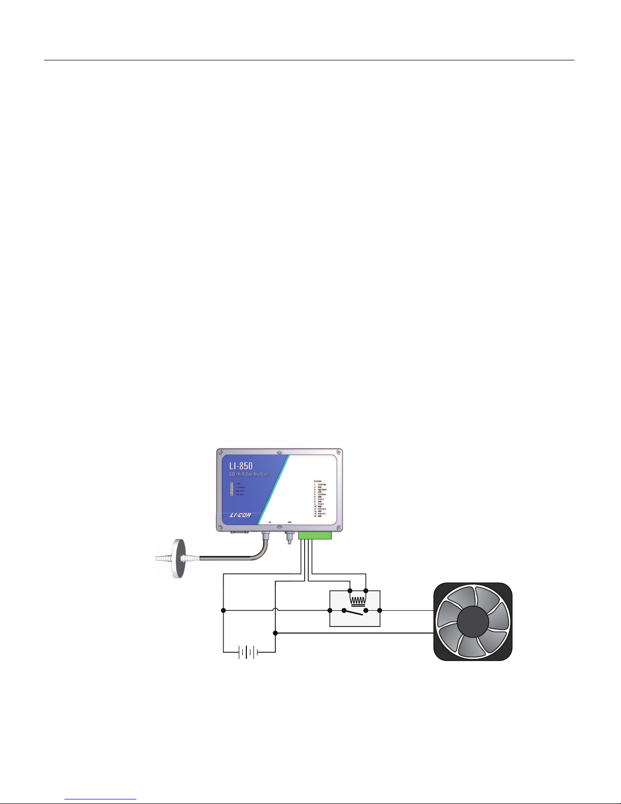
In TTL mode (transistor-to-transistor logic), the instrument sends a +5 V signal
when the alarm is off and a 0 V signal when it is on. The alarm can be used to
activate a relay switch or send a digital signal, for example. In Open collector mode,
the alarm works like a switch. There is infinite resistance when the alarm is off and
low resistance when the alarm is on, allowing current to flow between the pins.
Alarms are configured under Settings > Alarm Thresholds. To configure the alarms:
1
Check Enable Alarms.
Select whether the alarm should be for CO2or H2O (with the LI-850). Alarms can
be set for one or the other, not both.
2
Configure the High Alarms.
l The ON settings is the high level at which the alarm is activated.
l The OFFsetting is the level at which the alarm is deactivated. The deadband is
the range between the ON and OFF settings.
3
Configure the Low Alarms.
l Again, the ON setting is the low level at which the alarm is activated.
l The OFF setting is level at which alarm is deactivated. The deadband is the range
between the ON and OFFsettings.
4
Click Apply when you are done.
12 VDC Power Supply
+ -
5 V Relay
Fan
Air
Inlet
1 2 3 4
Filter
Figure 2-4. In this example, the high alarm is used to activate a relay, which turns on a
fan.
Section 2. Configuring the gas analyzer
2-9Using alarms
Page 26
Section 2. Configuring the gas analyzer
Using the Pump
For instruments that are equipped with the LI-COR-installed pump, the pump is
activated through the interface.
Note: The pump will not run until the optical cell has reached the operating
temperature of about 50 °C, regardless of the setting. If the cell temperature
drops below 50 °C, the instrument will disable the pump temporarily until the
cell warms back up.
To turn on the pump from the main window, click the pump button so it reads
Pump: On. Or, click Settings > Instrument and check Enable pump.
2-10 Using the LI-830 and LI-850 Gas Analyzers
Page 27

Section 3.
Troubleshooting
In this section, we describe how to identify some potential problems. If you can't
find a solution here, contact your local distributor or LI-COR technical support for
more help.
Instrument will not power on
Power supply adequate? The power supply should source at least 1.2 amps at 12
VDC (minimum of 14 watts during warmup).
Blown fuse? The instrument can be powered from the power jack or pins one and
two on the terminal strip. Each connection has its own fuse.
l If you are unable to power on the instrument using the jack, but can power it
on using the terminal strip, you probably have a blown power jack fuse.
l If the opposite is true, you probably have a blown terminal strip fuse.
l If you can't power it using either connection, you may have blown both fuses.
Check the resistance across the fuse contacts using an ohm meter. A reading of 0
means that the fuse is good; a reading of 1 indicates that the fuse is blown.
See Replacing a fuse on page4-6 for complete instructions.
Unable to span or zero the instrument
Dirt in the optics? If the optical cell becomes contaminated, the instrument will
drift in either the zero or span.
See Cleaning the optical bench on page4-4 for complete instructions.
3-1Using the LI-830 and LI-850 Gas Analyzers
Page 28

Section 3. Troubleshooting
Instrument reports -50 ppm CO2or measurements
jump around
If the instrument measures -50 ppm or the measurements are going between negative and positive values, or just simply not making any sense, the optical source
may have failed or be in the midst of failure. Contact technical support for additional troubleshooting help.
3-2 Using the LI-830 and LI-850 Gas Analyzers
Page 29

Section 4.
Maintenance
The LI-830 and LI-850 will require little maintenance. Typical maintenance procedures are described in this section.
User calibration
If the instrument is not measuring as expected, or if you have disassembled the
optical bench for any reason, you should check the zero and span settings and set
them if necessary. The zero and span are an offset and slope. The zero value ensures
that the instrument shows zero when the gas has a zero concentration. A change in
the zero will affect every measurement. The span setting ensures a correct measurement at a known non-zero concentration. A change in the span affects higher
concentration measurements more than lower ones.
Setting the CO2zero
Always perform the zero first. To set the zero, you'll need either a tank of dry air
that is free of CO2or a CO2scrubbing chemical such as wet soda lime and a desiccant such as Drierite.
1
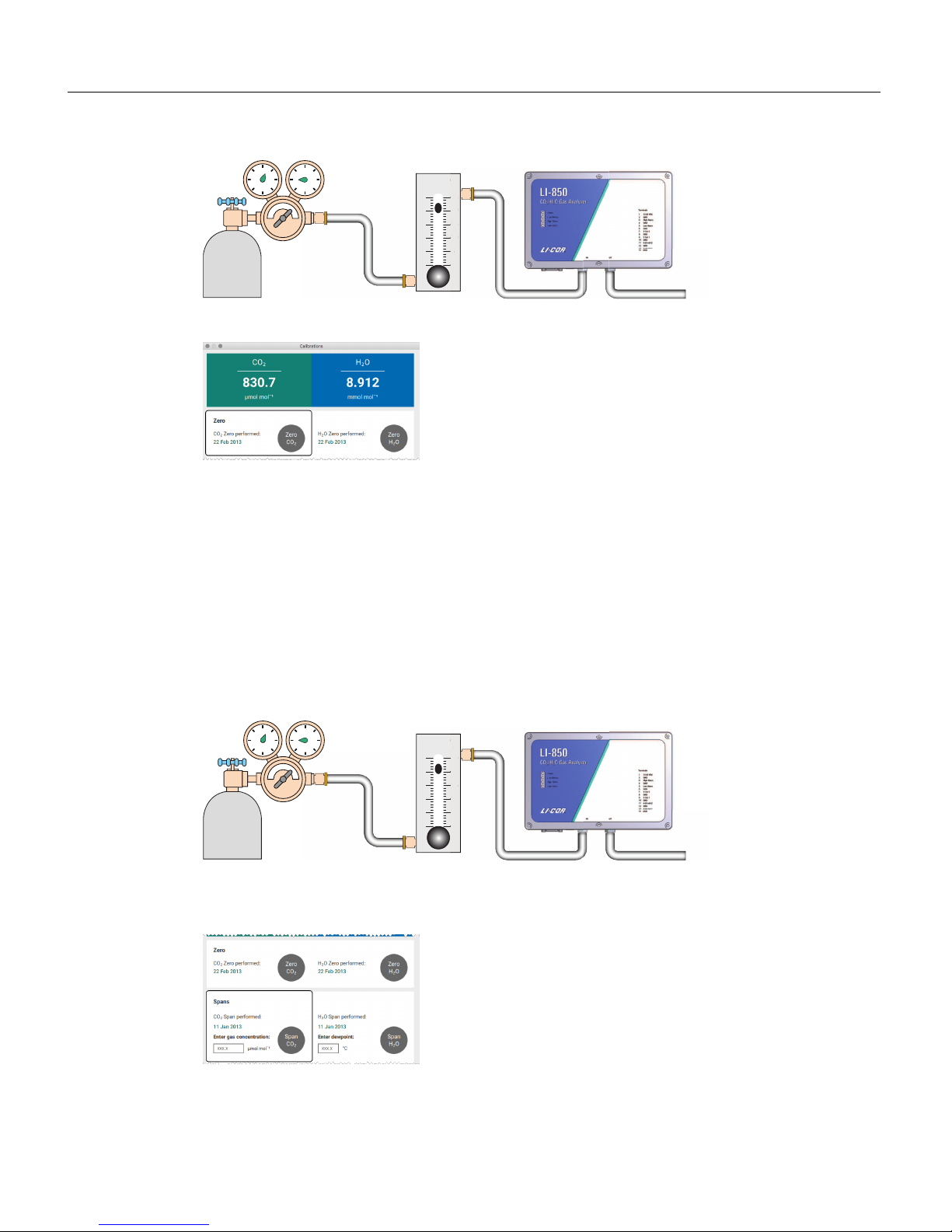
Plumb the zero-gas tank or scrubber to the air inlet.
Be sure to use an air filter to prevent contaminants from entering the optical path.
l If using tank air, the pressure of the tank is sufficient to flow the gas through
the analyzer. Allow at least 0.75 liters per minute to flow through the cell (no
more than 1.0 lpm).
l If using a scrubbing chemical, use a pump to draw air through the analyzer.
2
Install a 10 to 20 cm length of tubing to the air outlet.
This vent prevents ambient air from diffusing upstream into the optical cell.
4-1Using the LI-830 and LI-850 Gas Analyzers
Page 30
Section 4. Maintenance
Zero
Gas
Regulator
Rotameter
× 100 cc/min
5
10
20
15
25
in
5
10
20
15
25
Flow Meter
Vent
3
When the CO2concentration has stabilized, click the Zero CO2button.
Setting the primary CO2span
When choosing a span gas, we recommend a gas concentration that is close to the
upper limit of what you expect to measure. For example, if you are measuring nearambient levels, choose a span gas that is near 400 ppm CO2(as opposed to 18,000
ppm). Similarly, if you are measuring concentrations near 15,000 ppm CO2, a span
gas with 100 ppm would not be ideal.
4
After zeroing, flow a gas with a known CO2concentration through the analyzer at a rate of 0.5
liters per minute.
CO2
Span
Gas
Regulator
Rotameter
× 100 cc/min
5
10
20
15
25
r
in
5
10
20
15
25
Flow Meter
Vent
5
Enter the CO2concentration of the span gas into the software
6
When the CO2reading has stabilized, click Span CO2.
4-2 Using the LI-830 and LI-850 Gas Analyzers
Page 31
Setting the secondary CO2span
You can set a second span (using a gas that has a CO2concentration that is higher
or lower than the primary span gas) to improve the precision of the analyzer. The
process is exactly the same as setting the primary span, only you'll enter a different
concentration and click Span2 CO2.
Setting the H2O zero and spans (LI-850 only)
The water vapor span can be set with a dew point generator such as the LI-610. The
procedure is the same as setting the CO2zero and spans, only this uses known concentrations of water vapor rather than CO2.
Caution: Setting the zero and span incorrectly for either CO2or H2O will
adversely impact the performance of your instrument. If you do not have the
proper equipment to span the analyzer, it is best to leave it alone.
Recovering from a bad zero or span
If your attempt to zero or span does not go as planned, you can restore the factory
default zero and span settings. The information you need is provided on the calibration sheet (included with the instrument or available for download from
www.licor.com/env/support/). Under Settings > Calibrations > Advanced, enter the
factory zero and span values for your instrument.
Section 4. Maintenance
4-3Setting the secondary CO2 span
Page 32
Section 4. Maintenance
Cleaning the optical bench
The optical bench can be removed and cleaned if necessary. If, for example, you are
unable to set the span, the optics may be contaminated. Generally speaking, don't
undertake this procedure unless you've ruled out other potential problems. You'll
have to set the instrument zero and span after reassembling the optical bench.
1
Turn off the instrument.
Unplug the power cable.
2
Remove the top cover.
It is attached with 6 captive screws. Loosen each of the screws until the top cover is
free of the bottom. If your instrument has a display, carefully rotate the top cover
out of the way without straining the cable, and then unplug the display cable. Set
the cover aside, being careful not to strain the ribbon cable.
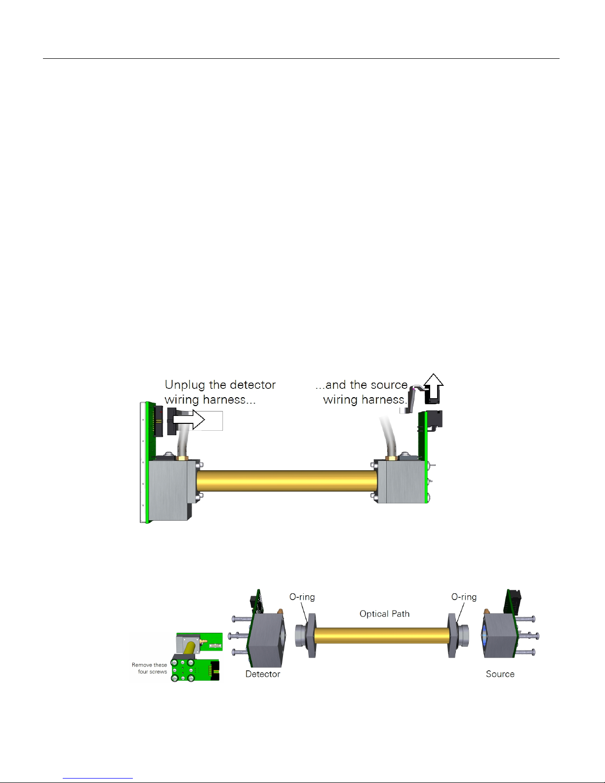
3
Remove the cables from the source and detector.
Gently grasp the plug and pull it free of the assembly. Leave the tubes in place.
4
Carefully lift the optical bench out of the foam.
5
Remove the screws that secure the source and detector (4 each), then separate the source and
detector housings (with circuit boards attached) from the optical path.
4-4 Using the LI-830 and LI-850 Gas Analyzers
Page 33
6
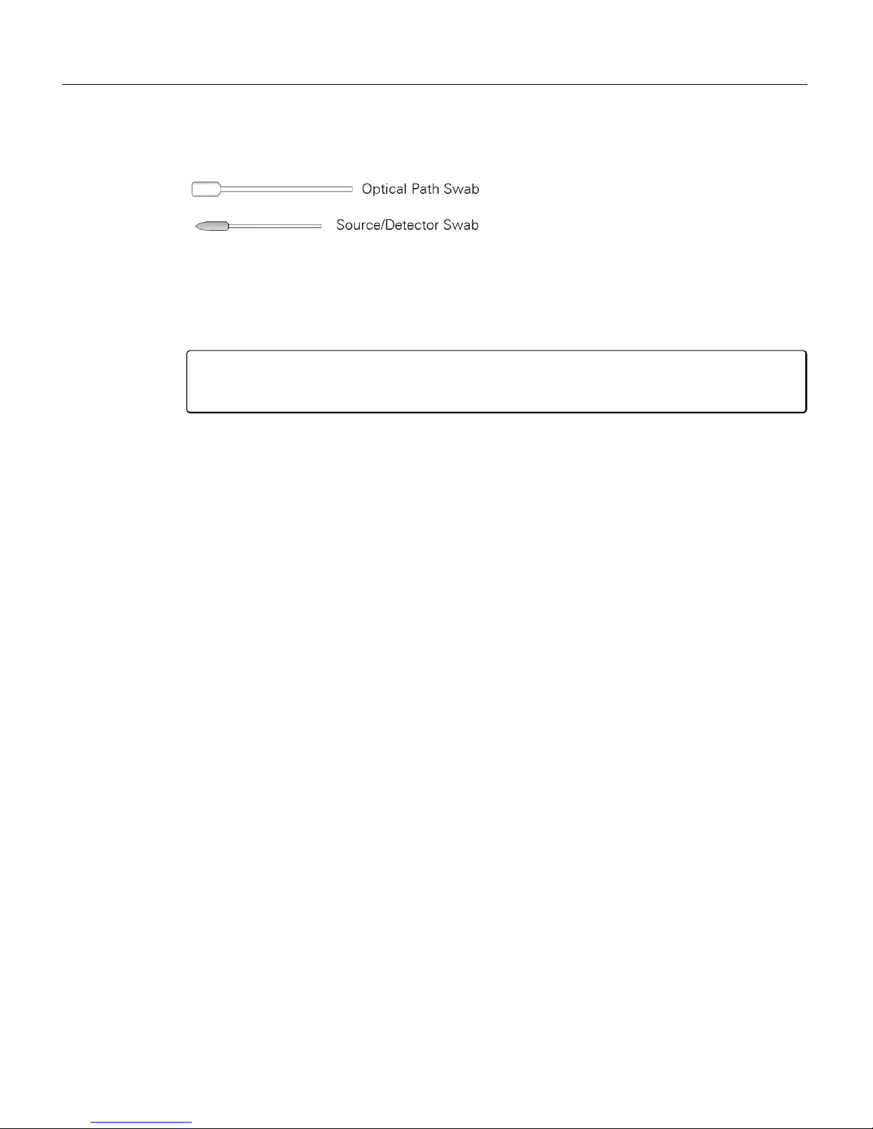
Clean the parts.
Retrieve an optical path swab from the accessories kit. Dip one end into a 50:50 ethanol-water mixture (mild dish washing soap and water will work too) and carefully
swab both ends of the optical path. Dip a Source/Detector swab into the solution
and then swab around the source and detector to remove any residue.
Caution: Do not use abrasive cleansers. Abrasive cleaners can irreparably damage
the gold plating on the optical path, source, or detector.
7
Inspect the hose barbs and tubing.
If the tubes are dirty or damaged, replace them with new tubes (available from
LI-COR, part number 6580-041). Carefully remove them from the hose barbs. If
the tubes are in good condition and clean, you may be able to reuse them. If the
hose barbs are dirty, remove them and clean them with rubbing alcohol or soapy
water. Use caution: Do not scratch the hose barbs because scratches may cause
leaks.
8
Inspect the O-rings.
If they are smashed flat or damaged in any way, replace them with new O-rings
(part number 192-00226) from the accessories kit.
9
Let the optical bench components dry.
10
Reassemble the optical bench.
Attach the source and detector. The orientation of the optical path cylinder is unimportant — either end can be inserted into the source and detector housing. Tighten
each of the screws snugly.
11
Place the optical bench in the foam, plug in the source and detector connectors, and re-assemble
the case.
Be sure the foam insulation on the top cover is positioned over the optical bench. It
is required for thermal stability.
12
Perform a zero and span calibration. See User calibration on page4-1.
Section 4. Maintenance
4-5Cleaning the optical bench
Page 34
Section 4. Maintenance
Replacing a fuse
The power supply and terminal strip are both protected by fuses. The instrument
has one extra fuse (Littel Fuse 476 Series Nano2®6.3 amp fuse) that can be used in
the event that one of the fuses blows. If you are able to power on the instrument
using one of these two ways—but not the other—a fuse may be blown. If you can't
power the instrument using either way, both fuses may be blown (or you may have
a power supply issue).
Before simply replacing a fuse, be sure to identify the problem that caused the fuse
to blow in the first place. Otherwise, you'll just blow the spare fuse, in which case,
you'll still have the problem and you'll be out of spare fuses. After identifying and
solving the problem that caused the fuse to blow, replace the fuse:
1
Open the case.
Loosen each of the six top cover screws until the top cover is free of the bottom. If
your instrument has a display, carefully rotate the top cover out of the way without
straining the cable, and then unplug the display cable. Set the cover aside.
2
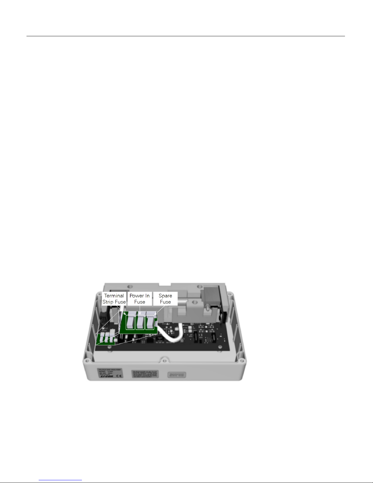
Locate the fuses.
With the air-in and -out ports facing away from you, the fuses are mounted to the
lower left corner of the lowest circuit board. In the image, ribbon cables and tubes
have been removed for clarity.
3
Using a needle-nose pliers, grasp the blown fuse and remove it from the holder.
4
Replace it with a spare fuse.
5
Power on the instrument to verify that the issue is resolved.
4-6 Using the LI-830 and LI-850 Gas Analyzers
Page 35

A-1Using the LI-830 and LI-850 Gas Analyzers
Appendix A.
Equation Summary
The LI-830 and LI-850 compute CO2concentrations using an equation of the form
A-1
where c is concentration, f() is the calibration function,α" is the absorptance, g
(α,P) is the pressure correction, S(α) is the span, and T is the temperature (°C) of
the gas in the cell, typically 51.5 °C. Absorptance is computed from
A-2
α
' is a span corrected absorptance, and g(α',P) is the pressure correction.
A-3
S(α) is the span function, and raw absorptanceαis computed from
A-4
where V and Voare the raw detector sample and reference readings, and Z is the
zeroing parameter.
Span is a linear function of absorptance.
A-5
Page 36
Appendix A. Equation Summary
H2O Equations (LI-850 only)
Absorptance
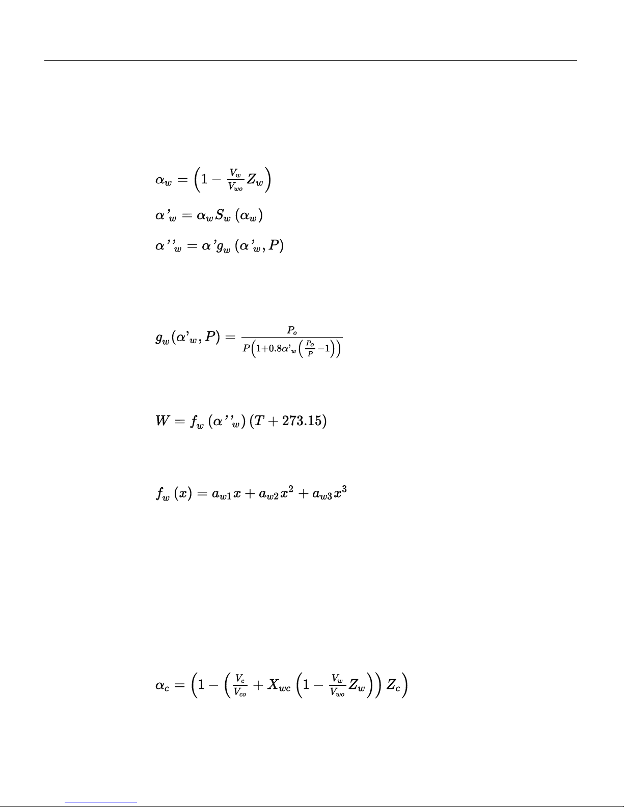
α
ω
for water vapor is computed from
A-6
where Vwand Vwoare the sample and reference raw detector readings, and Zwis
the zero parameter. The pressure correction for water vapor is an empirical function gw() of absorptance and pressure P:
A-7
The value of Pois 99 kPa. When the pressure correction is not enabled, gw() is
simply 1.0. Water vapor concentration W (mmol mol-1) is computed from
A-8
where fw(x) is a third order polynomial whose coefficients are given on the calibration sheet.
A-9
CO2Equations
The measurement of CO2is a bit more complicated than for H2O because of the
influence of water vapor. There is a slight direct cross sensitivity in the CO2signal
to H2O. This is measured at the factory and accounted for in the computation of
absorptance (equation A-10). There is also a band broadening effect that is accounted for in the computation of concentration (equation A-14).
CO2absorptanceαc is computed from
A-10
A-2 Using the LI-830 and LI-850 Gas Analyzers
Page 37

where Vcand Vcoare the raw detector signals for sample and reference, Zcis the
CO2zero parameter, and Xwcis a cross sensitivity parameter for the effect of water
vapor on CO2. Its value is reported on the calibration sheet as XS=.
The empirical pressure correction function gc() depends on CO2absorptance and
pressure:
When P = Po, gc() = 1.
When P < P
o
A-11
where a = 1.10158, b = -6.1217E-3, c = -0.266278, d = 3.69895, and z is the asymptotic value of absorptance, obtained from the calibration coefficients (equation
A-15).
A-12
When P > P
o
A-13
where X, A, and B are computed as in equation A-11. CO2concentration C (µmol
mol-1) is computed from
Appendix A. Equation Summary
A-3Appendix A. Equation Summary
Page 38
Appendix A. Equation Summary
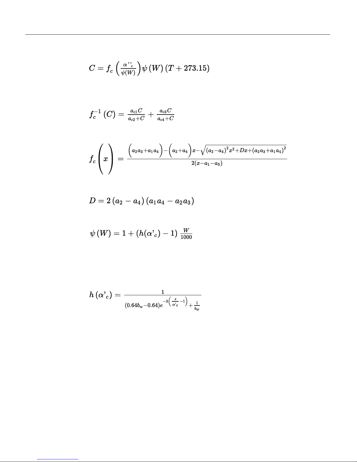
A-14
where fc(x) is a function whose inverse is a double rectangular hyperbola, and
whose coefficients (a1…a4) are given on the calibration sheet.
A-15
Solving equation A-15 for C yields the calibration function
A-16
Where
A-17
ψ (W) accounts for band broadening by water vapor.
A-18
The band broadening coefficient h(α'c) has been determined to be 1.45 for the
instrument for CO2concentrations near ambient. At higher concentrations, the
value decreases. We capture this behavior with an empirical relationship (equation
A-19).
A-19
Where z is from equation A-12, and bwis the low concentration band broadening
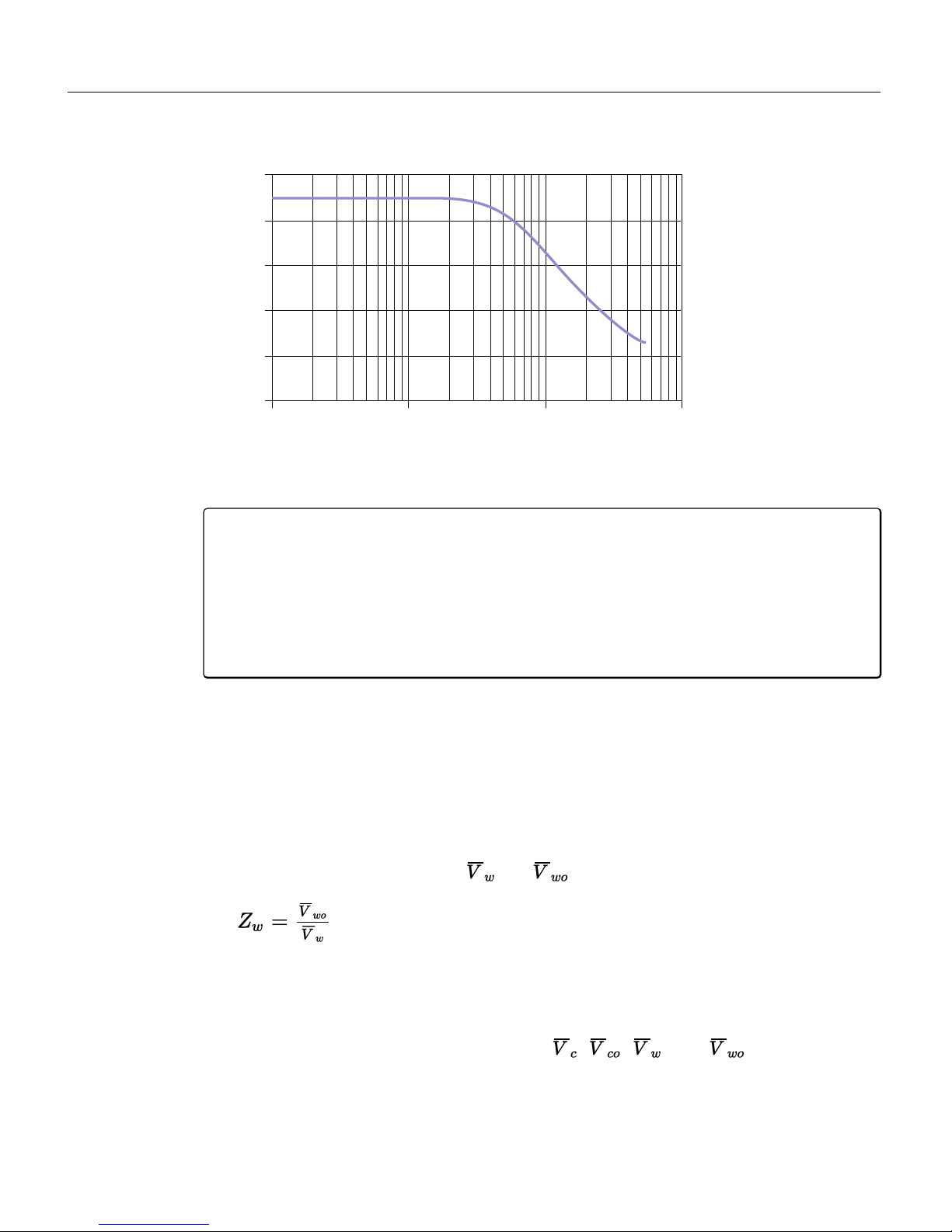
coefficient: 1.45. This is the value shown on the calibration sheet as BB = 1.45.The
typical relationship between h(α'c) and CO2concentration is shown in Figure A-1
on the facing page. (‘Typical’ because the exact relationship depends on the rela-
tionship between absorptance and CO2, which is the calibration curve.)
A-4 Using the LI-830 and LI-850 Gas Analyzers
Page 39
100 1000 10000 100000
Approximate CO Concentration (ppm)
Bandbroadening Coefficient for HO
1.5
1.4
1.3
1.2
1.1
1.0
Figure A-1. The typical relationship between h(α'
c
) and CO2concentration.
Note: We formulated equation A-19 with 0.64bw– 0.64 instead of the simple
equivalent (0.29) because this allows band broadening corrections to be turned
off by setting bwto 1. When bw=1, h(
α
c
) = 1 everywhere. Also, to avoid com-
putational problems (underflows, overflows, and division by zero) we constrain
the argument
α
c
when computing h(
α
c
) to be 0.1 <
α
c
≤ z.
α
c
- 0.1 is typically
equivalent to about 600 ppm.
Calibration Equations
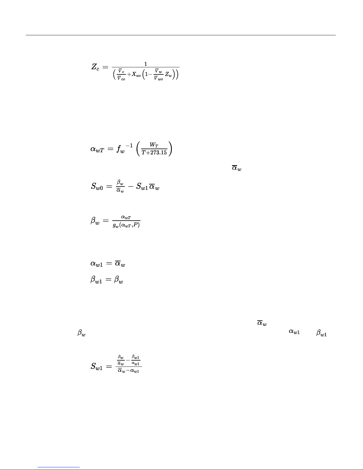
The following equations describe the implementation of zero and span calibrations.
Zeroing H2O (LI-850 only)
When the command for zeroing water is received, the LI-850 computes the water
zero from equation A-20, where and are averaged for 5 seconds.
A-20
Zeroing CO
2
When the command for zeroing CO2is received, the instrument computes the
CO2zero term from equation A-21, where , , , and are averaged for
5 seconds.
Appendix A. Equation Summary
A-5Appendix A. Equation Summary
Page 40
Appendix A. Equation Summary
A-21
Spanning H2O (LI-850 only)
When the command for setting the span for H2O is received, along with the target
concentration WT, from the target concentration, the target absoprtance
α
T
is com-
puted from
A-22
LI-850 computes Sw0from equation A-23 , where is averaged over five seconds.
A-23
where
A-24
The instrument retains the following values, which are used for subsequent secondary spans:
A-25
Secondary Span H2O (LI-850 only)
When the secondary span command for H2O is received, the instrument computes
new values for both Sw0and Sw1. First, it measures a new and computes a new
from equation A-24. Then, it uses these plus the retained values ( and
from the previous normal span) to compute
A-26
Given the new span slope Sw1, it updates the span offset Sw0by equation A-23.
A-6 Using the LI-830 and LI-850 Gas Analyzers
Page 41
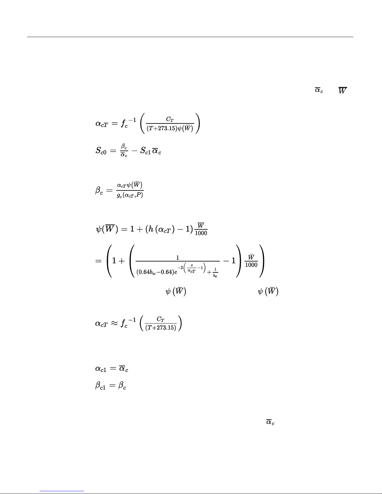
Spanning CO
2
When the command for setting the CO2span is received, along with the target concentration CT, the instrument computes Sc0from equation A-28, where and
are averaged for 5 seconds.
A-27
A-28
where
A-29
Note that
A-30
We needαcT to compute , butαcT depends on . We resolve this by
using an approximation (equation A-31) instead when computing equation A-30
A-31
The instrument retains the following values, which are used for subsequent secondary spans, if necessary:
A-32
A-33
Secondary Span CO
2
When the secondary span command for CO2is received, the instrument computes
new values for both Sc0and Sc1. First, it measures a new and computes a new β
c
Appendix A. Equation Summary
A-7Appendix A. Equation Summary
Page 42

Appendix A. Equation Summary
from equation A-29. Then it uses these, plus the retained values (
α
c1
and βc1from
the previous normal span) to compute
A-34
Given the new span slope Sc1, it updates the span offset Sc0by equation A-28.
A-8 Using the LI-830 and LI-850 Gas Analyzers
Page 43

B-1Using the LI-830 and LI-850 Gas Analyzers
Appendix B.
Specifications
CO2measurements
Measurement range: 0 to 20,000 ppm
Accuracy
LI-850: Within 1.5% of reading
LI-830: Within 3% of reading
Calibration drift
Zero drift1: <0.15 ppm per °C
Span drift2: <0.03% per °C
Total drift at 370 ppm3: <0.4 ppm per °C
RMS noise at 370 ppm with 1 sec signal filtering: <1 ppm
Sensitivity to water vapor (LI-850 only): <0.1 ppm CO2/ mmol mol-1H2O
Lower limit of detection: 1.5 ppm
H2O measurements (LI-850 only)
Measurement range: 0 to 60 mmol mol
-1
Accuracy: Better than 1.5% of reading
Calibration drift
Drift at 0 mmol mol-1: <0.003 mmol mol-1per °C
Span drift at 10 mmol mol-1: <0.03% per °C
Total drift at 10 mmol mol-1: <0.009 mmol mol-1per °C
RMS noise at 10 mmol mol-1with 1 sec signal filtering: <0.01 mmol mol
-1
Sensitivity to CO2: <0.0001 mmol mol-1H2O / ppm CO
2
Lower limit of detection: 0.015 mmol mol
-1
1
Zero drift is the change with temperature at 0 concentration.
2
Span drift is the residual error after re-zeroing following a temperature change.
3
Total drift is the change with temperature without re-zeroing or re-spanning.
Page 44

Appendix B. Specifications
General
Output rate: Up to 2 measurements per second
Response time (T90)
CO2: <3.5 seconds from 0 to 375 ppm
H2O (LI-850 only): <3.5 seconds from 0 to 21 mmol mol
-1
Measurement principle: Non-Dispersive Infrared
Traceability
CO2: Traceable gases to WMO standards from 0 to 3,000 ppm; traceable gases
to EPA protocol gases from 3,000 to 20,000 ppm
H2O (LI-850 only): NIST traceable LI-610 Portable Dew Point Generator
Pressure compensation range: 50 to 110 kPa
Maximum gas flow rate: 1 liter min
-1
Output signals: Two analog voltage (0 to 2.5 V or 0 to 5 V) and two current (4 to
20 mA)
Digital outputs: TTL (0 to 5 V) or Open Collector
DAC resolution: 16 bits across user-specified range
Power requirements
Input voltage: 12-30 VDC
After warmup (without pump): 0.3 A @ 12 VDC (3.6 W) average
After warmup (with pump): 0.4 A @ 12 VDC (4.6 W) average
During warmup: 1.2 A @ 12 VDC (14 W) maximum
Operating temperature range: -20 to 45 °C
Relative humidity range: 0 to 95% RH, Non-condensing
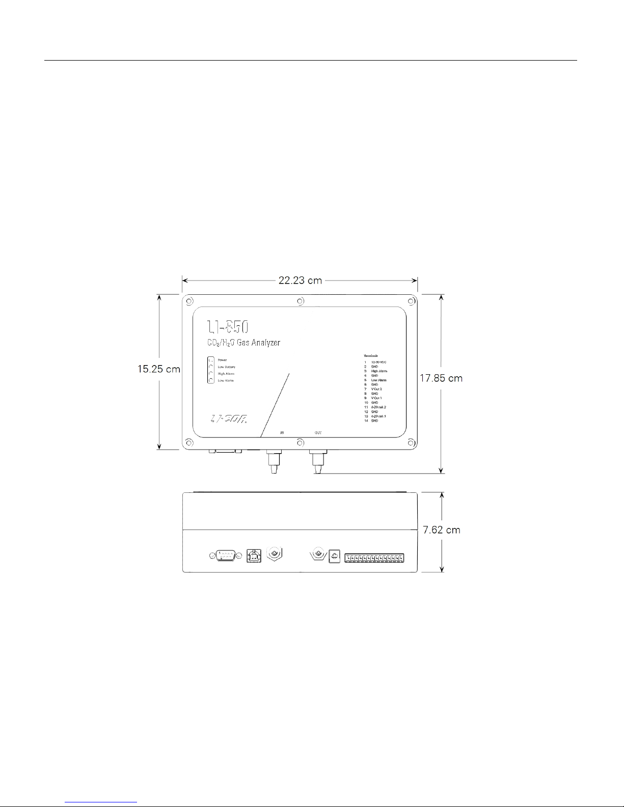
Dimensions: 22.23 cm W × 15.25 cm D × 7.62 cm H
Weight
No pump, no display: 1.0 kg
No pump, with display: 1.02 kg
With pump, no display: 1.3 kg
With pump, with display: 1.32 kg
Internal optical cell volume: 14.5 mL
Pump specifications (optional)
Operating temperature range: 5 to 45 °C
Storage temperature range: -20 to 60 °C
Operating humidity range: 0 to 80% RH
Nominal flow rate: 0.75 liters minute
-1
Power consumption: <0.75 W
Expected life span: 8,000 hrs in standard conditions with a normal load
B-2 Using the LI-830 and LI-850 Gas Analyzers
Page 45
Display specifications (optional)
Dimensions: 6.7 cm corner-to-corner
Resolution: 400 × 200 px; monochrome
Power consumption: <200 µW
Displayed variables: CO2reading, H2O reading (LI-850 only), optical bench tem-
perature, and pressure.
Specifications subject to change without prior notice.
Dimensional drawings
Appendix B. Specifications
B-3Appendix B. Specifications
Page 46
Appendix B. Specifications
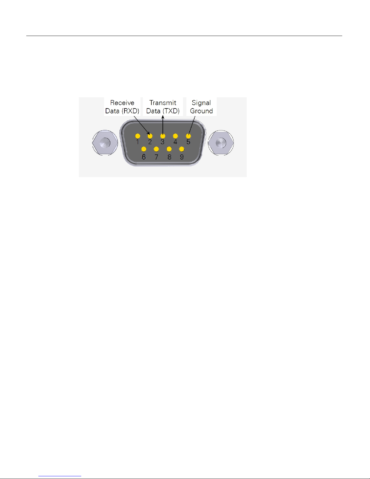
Serial cable pin assignments
The image below shows the pin assignments for the 9-pin RS-232 serial connector.
Serial communication parameters
The LI-830 and LI-850 can communicate through a RS-232 serial port on the front
of the instrument. You may need to set the communication parameters on your
computer or your terminal emulator program. The RS-232 port is configured as
Data Terminal Equipment (DTE) with no hardware handshaking. It is bi-directional, meaning information can be transferred both into and out of the instrument. The port is configured as follows:
l Baud Rate: 9600 bps
l Data Bits: 8
l Parity: None
l Stop Bits: 1
l Flow Control: None
B-4 Using the LI-830 and LI-850 Gas Analyzers
Page 47

C-1Using the LI-830 and LI-850 Gas Analyzers
Appendix C.
Warranty
Each LI-COR, Inc. instrument is warranted by LI-COR, Inc. to be free from defects
in material and workmanship; however, LI-COR, Inc.'s sole obligation under this
warranty shall be to repair or replace any part of the instrument which LI-COR,
Inc.'s examination discloses to have been defective in material or workmanship
without charge and only under the following conditions, which are:
1
The defects are called to the attention of LI-COR, Inc. in Lincoln, Nebraska, in writing within one
year after the shipping date of the instrument.
2
The instrument has not been maintained, repaired or altered by anyone who was not approved by
LI-COR, Inc.
3
The instrument was used in the normal, proper and ordinary manner and has not been abused,
altered, misused, neglected, involved in an accident or damaged by act of God or other casualty.
4
The purchaser, whether it is a DISTRIBUTOR or direct customer of LI-COR or a DISTRIBUTOR'S customer, packs and ships or delivers the instrument to LI-COR, Inc. at LI-COR Inc.'s factory in Lincoln,
Nebraska, U.S.A. within 30 days after LI-COR, Inc. has received written notice of the defect.
Unless other arrangements have been made in writing, transportation to LI-COR, Inc. (by air
unless otherwise authorized by LI-COR, Inc.) is at customer expense.
5
No-charge repair parts may be sent at LI-COR, Inc.'s sole discretion to the purchaser for installation by purchaser.
6
LI-COR, Inc.'s liability is limited to repair or replace any part of the instrument without charge if
LI-COR, Inc.'s examination disclosed that part to have been defective in material or workmanship.
There are no warranties, express or implied, including but not limited to any
implied warranty of merchantability of fitness for a particular purpose on
underwater cables or on expendables such as batteries, lamps, thermocouples,
and calibrations.
Page 48

Appendix C. Warranty
Other than the obligation of LI-COR, Inc. expressly set forth herein, LI-COR,
Inc. disclaims all warranties of merchantability or fitness for a particular purpose. The foregoing constitutes LI-COR, Inc.'s sole obligation and liability with
respect to damages resulting from the use or performance of the instrument
and in no event shall LI-COR, Inc. or its representatives be liable for damages
beyond the price paid for the instrument, or for direct, incidental or consequential damages.
The laws of some locations may not allow the exclusion or limitation on implied
warranties or on incidental or consequential damaged, so the limitations herein
may not apply directly. This warranty gives you specific legal rights, and you may
already have other rights which vary from state to state. All warranties that apply,
whether included by this contract or by law, are limited to the time period of this
warranty which is a twelve-month period commencing from the date the instrument is shipped to a user who is a customer or eighteen months from the date of
shipment to LI-COR, Inc.'s authorized distributor, whichever is earlier.
This warranty supersedes all warranties for products purchased prior to June 1,
1984, unless this warranty is later superseded. To the extent not superseded by the
terms of any extended warranty, the terms and conditions of LI-COR’s Warranty
still apply.
DISTRIBUTOR or the DISTRIBUTOR's customers may ship the instruments directly to LI-COR if they are unable to repair the instrument themselves even though
the DISTRIBUTOR has been approved for making such repairs and has agreed with
the customer to make such repairs as covered by this limited warranty.
Further information concerning this warranty may be obtained by writing or telephoning Warranty manager at LI-COR, Inc.
C-2 Using the LI-830 and LI-850 Gas Analyzers
Page 49

Page 50

cover_back_blank.pdf 1 8/15/16 1:28 PM
LI-COR Biosciences
464 7 Superior Street
Lincoln , Nebraska 68504
Phone: +1-402 -467-3576
Toll free: 800-44 7-357 6 (U.S. and Canada)
[email protected]
Regional Offices
LI-COR Biosciences GmbH
Siemensstraße 25A
613 52 Bad Homburg
Germany
Phone: +49 (0) 617 2 17 17 771
[email protected]
LI-COR Biosciences UK Ltd.
St. John’s Inno vation Centre
Cowley Road
Cambridge
CB4 0WS
United Kingdom
Phone: +44 (0) 122 3 422 10 2
[email protected]
LI-COR Distributor Network:
www.licor.com/env/distributors
984 -17190 • 09/18
 Loading...