

Page 1
Microsatellite
Analysis
Manual
Model 4300
DNA Analyzer
®
Page 2

iii
Page 3

Table of Contents
Section 1. Plate Organization
Introduction...................................................................................................1-1
The Hamilton 8-Channel Syringe...................................................................1-1
Microplate Configurations .............................................................................1-1
Section 2. Gel Preparation and Electrophoresis
Choosing Plates and Spacers .........................................................................2-1
Choosing a Gel..............................................................................................2-1
Plate Assembly ..............................................................................................2-2
Plus
Gel Preparation...................................................................................2-6
KB
Preparing Gel Solutions From Other Manufacturers.......................................2-7
Pouring a 6.5% KB
Pre-electrophoresis Preparation ...................................................................2-13
Starting Runs ...............................................................................................2-18
Sample Loading...........................................................................................2-18
Disassembly ................................................................................................2-19
Cleanup.......................................................................................................2-20
Plus
Gel...........................................................................2-10
Section 3. PCR Protocols
dNTP Recommendation ................................................................................3-1
PCR Optimization .........................................................................................3-1
Multiplexing Loci ..........................................................................................3-1
Microsatellite Optimization ...........................................................................3-2
Lab Organization...........................................................................................3-4
Preparing Genomic DNA ..............................................................................3-5
Size Standards ...............................................................................................3-5
Cycling Programs ..........................................................................................3-7
Tailed Primers................................................................................................3-9
Labeled Primers...........................................................................................3-11
Troubleshooting...........................................................................................3-13
iii
Page 4

Section 4. Appendices
T
Calculation ..............................................................................................4-1
m
Calculation of Oligonucleotide Concentration (nmol) Given
Optical Density (O.D.)...................................................................................4-2
Protocol for 96-well Paper Combs .................................................................4-3
iv
Page 5

Plate Organization
1
Section
Introduction
A system for the arrangement of samples in storage and reaction plates should
be established at the beginning of a microsatellite analysis project. Samples
should be placed in a specific arrangement in the plate to achieve the desired
sample order on the gel. These arrangements can be used for reaction processing
plates as well as stock plates that hold up to a milliliter of the DNA diluted to a
standard concentration.
A consistent volume for each DNA sample can be conveniently transferred to
the 96-well reaction plate with a multichannel pipette or a 96 needle Hydra
(Robbins Scientific). Ideally, samples from an entire family are stored on one
plate and aliquoted to 96-well plates at 20 to 50 ng/µl concentration. Plates are
stored at -20 °C until needed.
The Hamilton 8-Channel Syringe
The Hamilton 8-channel 0.2 mm syringe (Hamilton Co., Part #84511) has
syringe needles are spaced 9 mm apart. Since the wells formed by LI-COR
64-well combs are on 2.25 mm centers, the 8-channel syringe can be used to
load every fourth well of 0.25 mm gels. For 48-well combs, every third lane can
be loaded. LI-COR’s ClickIR Assembly for the Hamilton 8-channel syringe
assures consistent volume delivery through tactile feedback. The ClickIR
assembly attaches to the 8-channel syringe and allows the user to feel clicks that
correspond to 0.3 µl, 0.4 µl, or 0.5 µl (selectable) as sample is dispensed.
Assembly instructions for the ClickIR Assembly can be found in the
Miscellaneous tab of this applications manual.
Microplate Configurations
The arrangement of samples and standards in microplates should be predefined
in order to achieve the desired order on the gel. Two arrangement examples for
64-well combs are shown in Figures 1-1 and 1-2. The wells in each microplate
1-1
Page 6
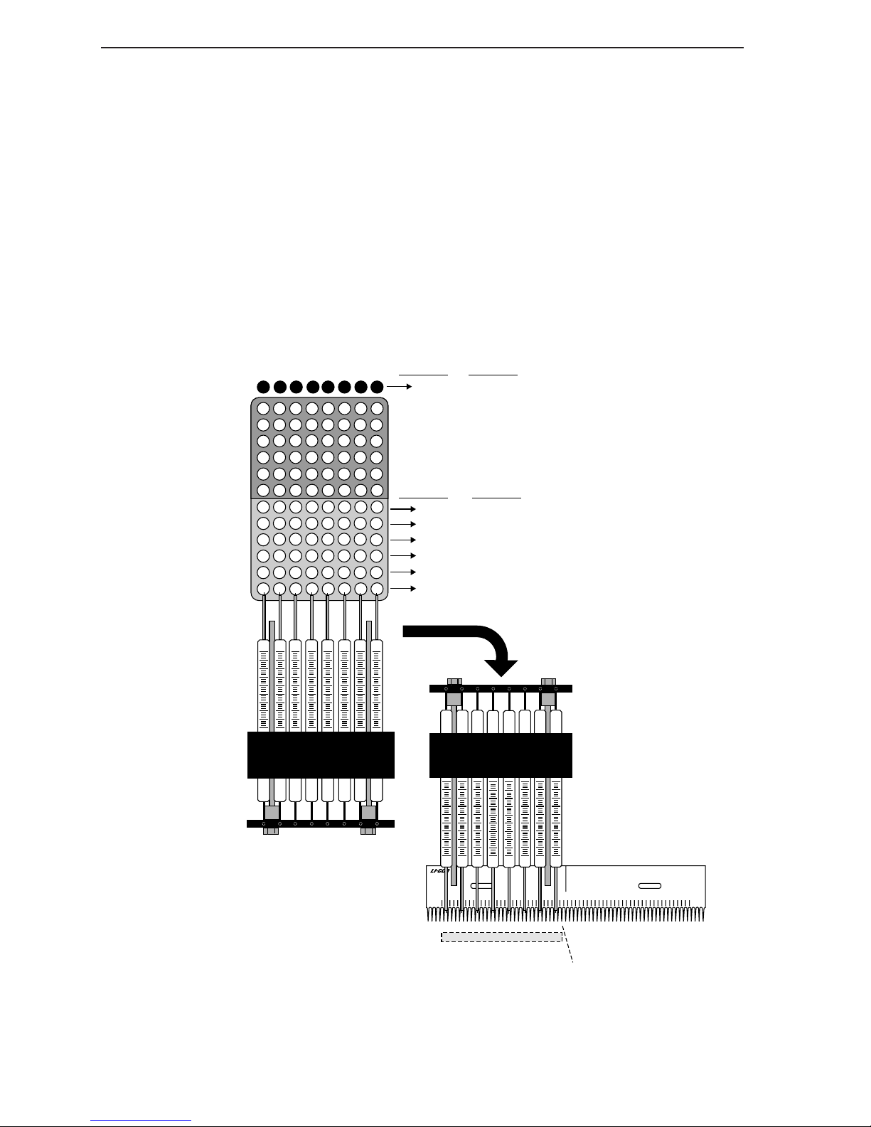
Section 1
are numbered according to the lane number that will be loaded. Both
configurations satisfy Saga’s requirement of at least 5 size standard lanes for dinucleotide repeats (7 lanes or more are better), as should any plate
configurations you design. The first example shows how to load half of a full
microplate on one gel and the other half on a second gel. The second example
shows how to configure a microplate for loading 60 samples on a 64-well
comb.
Loading 48 Samples on a 64-well Comb
In this configuration, size standards are loaded into every fourth lane. Size
standards (designated "S") are loaded from a second plate or a set of strip tubes.
An entire microplate can therefore be loaded onto two gels.
Gel #2
Gel #1
Load #
SS
27
30
29
26
28
25
6
3
5
2
4
1
27
30
26
29
28
25
6
3
5
2
4
1
S
39
38
37
15
14
13
38
37
15
14
13
SSS
42
45
44
41
40
43
21
18
17
20
19 22
16
45
42
41
44
43
40
21
18
17
16 19 22
48
47
46
24
23
Load #
48
47
46
24
2320
7
6
4
3
2
S
S
36
33
32
35
31
34
9
12
8
11
10
7
33
36 39
32
35
31
34
9
12
8
11
10
7
Left syringe tip
starts at well #:
1 & 331 & 5
Left syringe tip
starts at well #:
368
35
34
4
3
2
Figure 1-1. Microplate showing 48 sample loading format. Size standards are loaded
from a second plate or set of strip tubes.
1-2
®
5
1 3 7 9 11 13 15 17 211923 25 27 29 31 3533 37 39 41 43 45 4947 51 53 55 57 59 6361
SS SSSSSSSS SSSSSS
1st Load
2nd Load
3rd Load
4th Load
14 10713161922
25 11814172023
36 12915182124
25 28 3431 37 40 43 46
26 29 3532 38 41 44 47
27 30 3633 39 42 45 48
5th Load
6th Load
7th Load
8th Load
Page 7
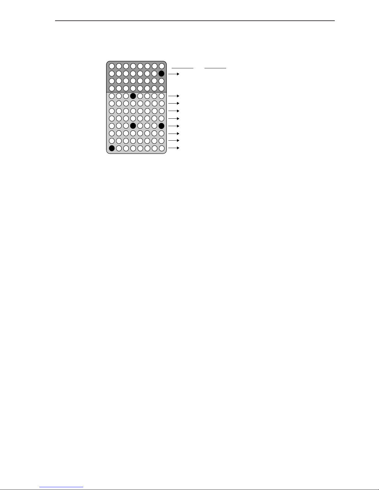
Plate Organization
Loading 60 Samples on a 64-well Comb
Load #
S
37
33
41
S
32
31
30
3
2
1
S
44
36
40
35
43
39
38
42
34
11
7
S
6
10
14
5
9
13
4
12
8
56 60
52
48
59
55
51
47
46
50
54
58
53
45
18
17
16
15
57
49
22
26
S
21
25
29
20
2824
19
23 27
9
7
6
5
4
3
2
11
Left syringe tip
starts at well #:
final load (a single
lane) goes in lane 65
368
35
34
33
4
3
2
Figure 1-2. Microplate showing
60 sample loading format.
1-3
Page 8

iii
Page 9
Gel Preparation and
2
Section
Electrophoresis
Choosing Plates and Spacers
18 and 25 cm gel plates are both suitable for microsatellite analysis
applications. Tri- and tetranucleotide repeats, as well as dinucleotide loci are
clearly resolved on 18 cm gels, providing accurate data. However, for complex
dinucleotide repeats, 25 cm gels provide increased resolution. 18 cm gels
typically resolve fragments of 350 base pairs in 1 hour, while 25 cm gels require
1.5 hours. 0.25 mm spacers should be used with either gel height.
Choosing a Gel
Use 25 cm gels for standard runs since they provide optimum resolution and
have adequate run speeds. Each gel can be loaded up to three times. Throughput
can be increased by using 18 cm gels since they require less time for
electrophoresis between successive loads. 18 cm gels give good performance
with increased speed for many applications.
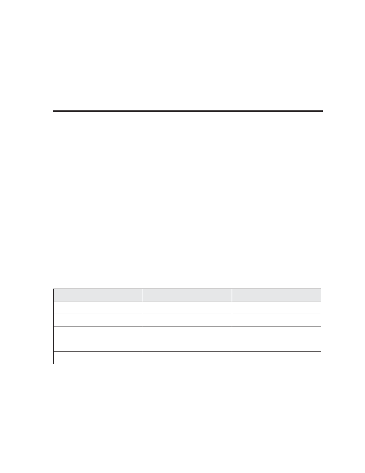
Table 2-1. Parameters for Standard and Fast Run gels.
Parameter Standard Run Fast Run
Plate Length 25 cm 18 cm
Spacer Thickness 0.25 mm 0.25 mm
Gel Composition 6.5% LI-COR KB
Run time (for 350 bases) 1.25 hours 45 minutes
Reload gel after 1.5 hours 1 hour
Plus
6.5% LI-COR KB
Plus
2-1
Page 10
Section 2
Plate Assembly
The following items are required to assemble the electrophoresis apparatus:
• Gloves (non-powdered)
• Safety glasses
• Non-abrasive tissues (Kaydry and Kimwipes)
• Front plate (notched)
• Back plate (rectangular)
• 1 set of spacers
• Comb
• 1 set of rail assemblies
• Casting plate
• Casting stand (optional)
• Concentrated laboratory detergent solution (Micro, Liquinox, etc.
detergent and tap water)
• Deionized water ( ≈ 18.0 MOhm)
• 3-(trimethoxysilyl)propyl methacrylate 98% (bind silane)
• 10% acetic acid
• Test tube or centrifuge tube (must hold 170 µl of liquid)
• Isopropanol (70 - 100%)
Caution: Always follow proper laboratory safety procedures.
Always wear gloves and safety glasses when working with
chemicals.
Cleaning the Plates
Materials needed:
• 2% laboratory detergent solution made from a concentrate such as Micro
(International Products Corp., Burlington NJ), or Liquinox (Alconox Inc., New
York, NY).
• Spray bottle capable of spraying a fine mist, containing 70% ethanol.
1. Pour a small amount (6 cm circle) of 2% detergent onto the side of the
plate that will contact the gel.
2. Work the solution into a lather with the bristle brush included, and
thoroughly scrub the entire plate. Remove any dried-on polyacrylamide with a razor blade, if necessary. Rinse well with water.
Buffer solution that has dried onto the plates can be removed with 1N
NaOH.
3. Pour distilled water onto the plate. Work the water around the plate
with a gloved hand and watch for bubble formation from detergent
residue. Repeat until no bubbles form.
4. Repeat steps 1-3 above with the second plate.
2-2
Page 11
Gel Preparation and Electrophoresis
5. Rinse the plates with deionized distilled water. Use a pump spray bottle
to spray a fine mist of 70% ethanol/ddH
O for a final rinse. Stand plates
2
in a rack to air dry.
Preparing Stock Bind Silane Solution
1. Add 50 µl of bind silane to 10 ml of 100% ethanol.
2. Mix well and store at 4 °C in an amber colored bottle, or wrap the
bottle in aluminum foil.
Silane treatments are used in autoradiography to facilitate removal of the gel
from the plates for exposure to film after electrophoresis. Infrared fluorescence
detection does not require repelling silane treatments because DNA bands are
detected in the gel, in real time, during electrophoresis.
3-(trimethoxysilyl)propyl methacrylate (98%), however, is a binding silane used
to covalently bind the gel to the glass in the area where the comb is inserted.
This treatment helps maintain good well morphology when loading gels multi-
ple times.
Applying the Bind Silane Solution
1. Combine 25 µl of stock bind silane solution and 25 µl of 10% acetic
acid in a 1.5 ml microcentrifuge tube. Mix thoroughly (pipette or
vortex).
2-3
Page 12
Section 2
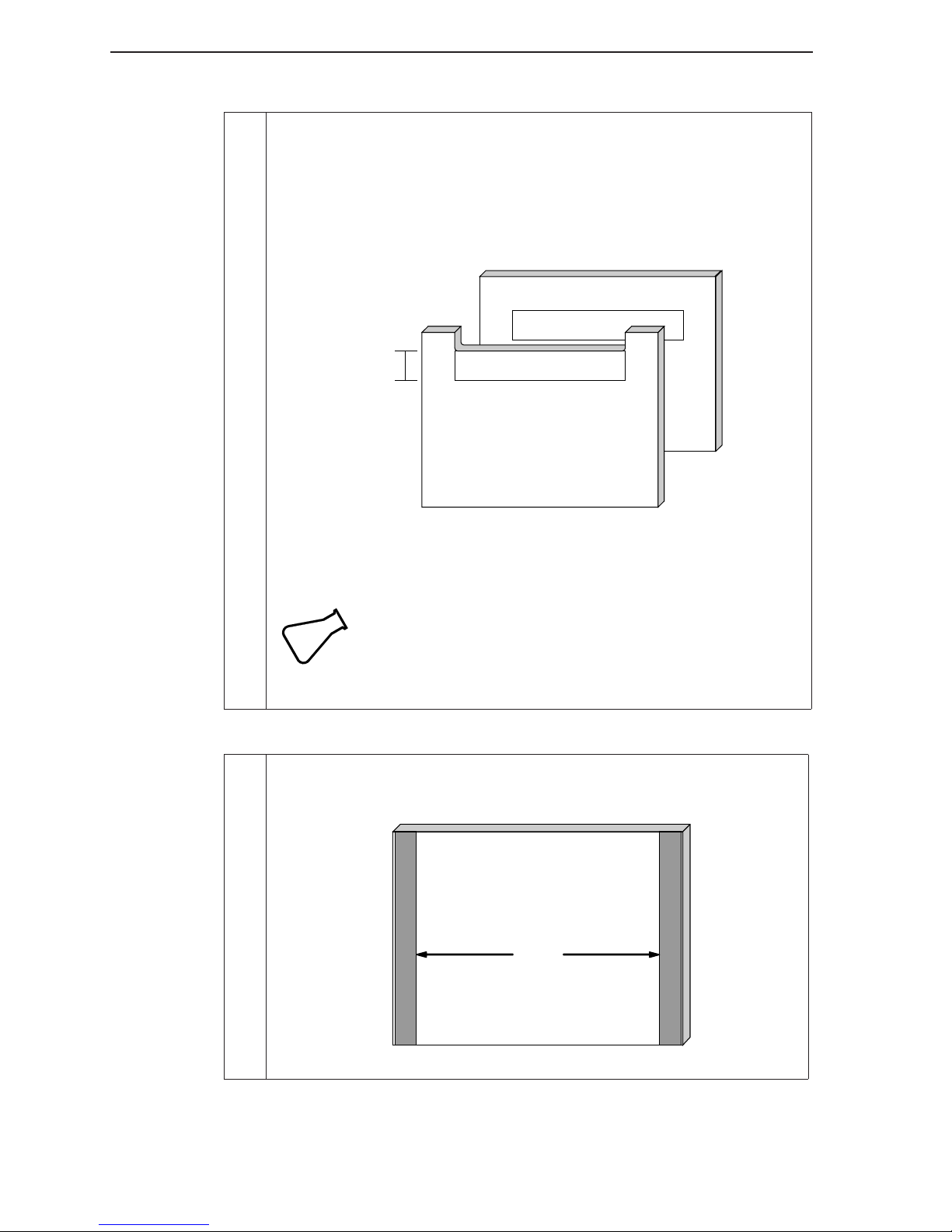
2. Use a cotton swab to apply the solution on the inside of the short plate
over the area below the edge of the notch where the wells will form
(Figure 2-1). If you are using a squaretooth comb, apply solution to the
rear plate using the front plate as a guide to determine where to place
the bind silane onto the rear plate (other combs do not require back
plate silane treatment). Allow the solution to dry before gel assembly.
Rear Plate
Apply bind silane here
1.5 cm
Figure 2-1 . Apply bind silane to the plates as shown.
Note that only squaretooth combs require back plate
silane treatment.
Apply bind silane here
Front Plate
Always put the beveled side of the plate to the inside (gel
Tip
side). The same side of the plates should always be on the
inside because over time the upper buffer tank gasket
leaves a permanent residue on the plate.
Assembling the Gel Sandwich
1. Lay the rear plate down (gel side up) and place the spacers along the
edges, as shown below.
2-4
Spacers
Rear Plate
Figure 2-2 . Place a spacer on the long edges of the plate.
Page 13
Gel Preparation and Electrophoresis
2. Place the front plate on top of the rear plate (gel side down) and align
the spacers with the outside edges of the plates. Make sure that the
plates are aligned evenly at the bottom.
3. Make sure the rails are completely dry from prior runs before assembly.
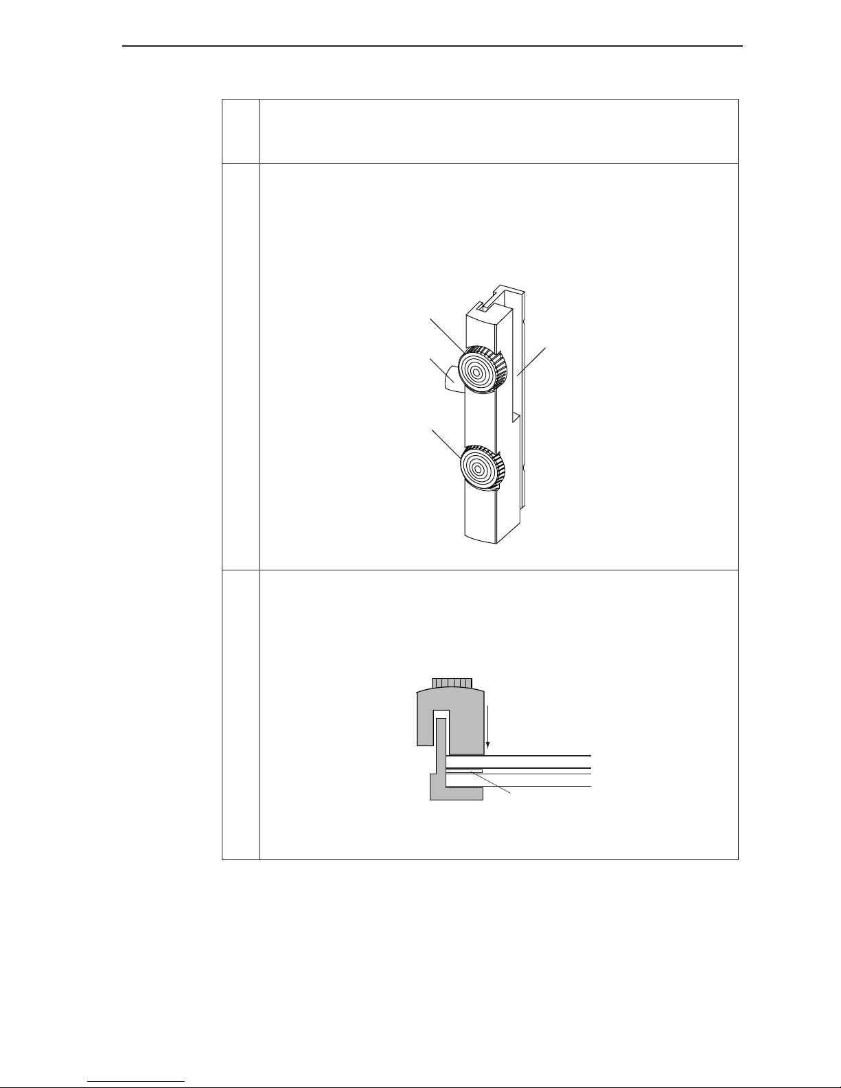
Place the left and right rail assemblies over the plate edges. Note that
the top portion of each rail is notched for insertion of the upper buffer
tank or casting plate (Figure 2-3). The uppermost clamp knob on each
rail is larger than the other one, as well.
Upper buffer tank
clamp knob
Support arm
Glass clamp knob
Groove for upper buffer
tank or casting plate
Figure 2-3 . Note orientation of rail assemblies (left rail shown).
4. Check to make sure the rails fit tightly against the edges of both glass
plates (Figure 2-4). The spacer must also be tight against the rail. A leak
will occur if there is a gap between the rail and either plate, or between
the rail and the spacer.
Rail
Notched Front Plate
Rear Plate
Spacer
Figure 2-4. Bottom view of assembled gel apparatus
showing the proper fit of the plates and spacer in the rail
2-5
Page 14
Section 2
5. Tighten the glass clamp knob on each rail. Tighten only until finger
tight (just past the point of resistance). Over tightening can break or dis-
tort the glass plates. Over tightening is also one of the primary causes of
“smiles” on gel images because distorted plates cause uneven band
migration across the gel.
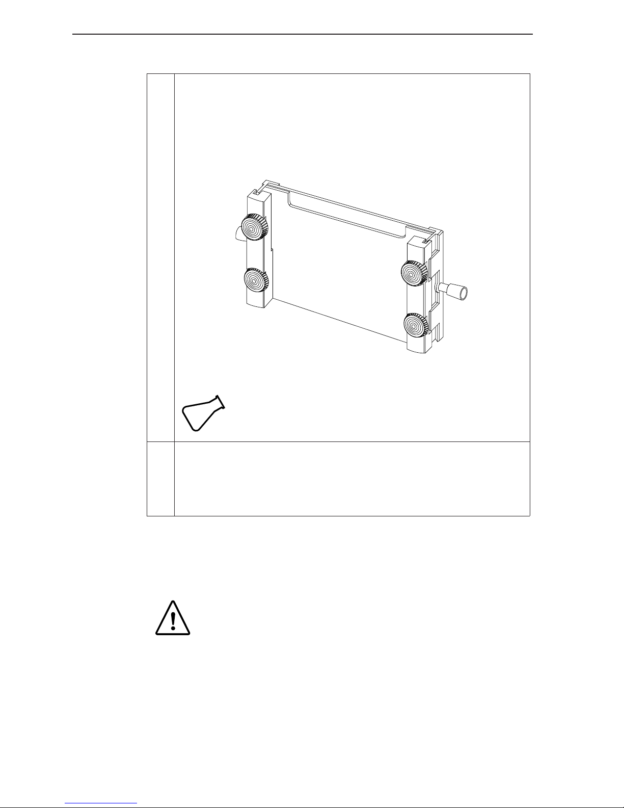
Assemble the apparatus as shown in Figure 2-5.
KB
Plus
Figure 2-5 . Assembled apparatus.
Recheck after tightening all knobs to make sure each knob is
Tip
6. Select a comb (sharkstooth or rectangular tooth comb) with thickness
that matches the spacers. Clean plastic combs with water and/or
ethanol if necessary. Make sure that the comb fits between the two
plates at the top of the gel, behind the notch in the front plate. If it
doesn't fit or is very loose, try another comb.
evenly tightened. Also, try to be consistent from day to day
when tightening the knobs.
Gel Preparation
Caution: Always follow proper laboratory safety procedures.
Always wear gloves and safety glasses when working with
chemicals.
Deionized Water Requirements
The conductivity of the water used in the gel and buffer should be 18 MOhm-cm
or greater.
2-6
Page 15
Gel Preparation and Electrophoresis
Preparing KB
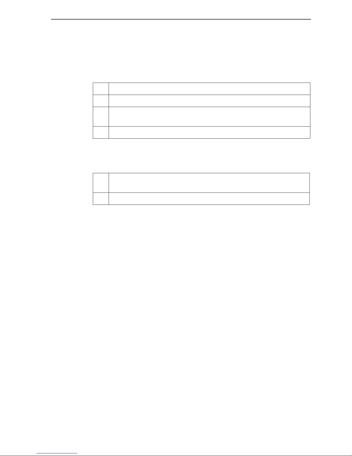
Gel and running buffer solutions are prepared from a standard 10x TBE buffer.
For best results, KB
10x TBE Buffer:
1. Empty the contents of the KB
2. Add enough distilled water (18M Ω ) to bring volume to about 800 ml.
3. Stir the solution well until all of the solids have gone into solution and
the solution is clear.
4. Add enough water to bring the final volume to 1000 ml.
Store at room temperature. Note that some precipitation may occur during
prolonged storage.
1X Running Buffer: (Use this buffer for electrophoresis.)
1. Add 100 ml of 10X TBE prepared as above to 900 ml of distilled water
(18M Ω ).
2. Mix well.
Plus
Buffer
Plus
buffer is recommended for use with KB
Plus
10X TBE pouch into a 1 liter beaker.
Plus
gel matrix.
Preparing Ammonium Persulfate Solution
APS provides a source of free radicals needed for polymerization of the gel
(Sambrook, 1989). A 10% APS solution is made by adding 0.1 g APS to 1.0 ml
deionized water in a small test tube. Prepare APS daily to ensure a fresh
working solution. "Stale" APS will adversely affect band quality and give bands a
“fuzzier” appearance with less distinct edges.
Preparing Gel Solutions From Other
Manufacturers
Deionized Water Requirements
The conductivity of the water used in the gel and buffer should be 18 MOhm-cm
or greater.
Preparing Buffer
Gel and running buffer solutions are prepared from a standard 10x TBE buffer.
Gels generally contain 1.0x-1.2x TBE while the running buffer is 0.8x-1.0x TBE.
2-7
Page 16
Section 2
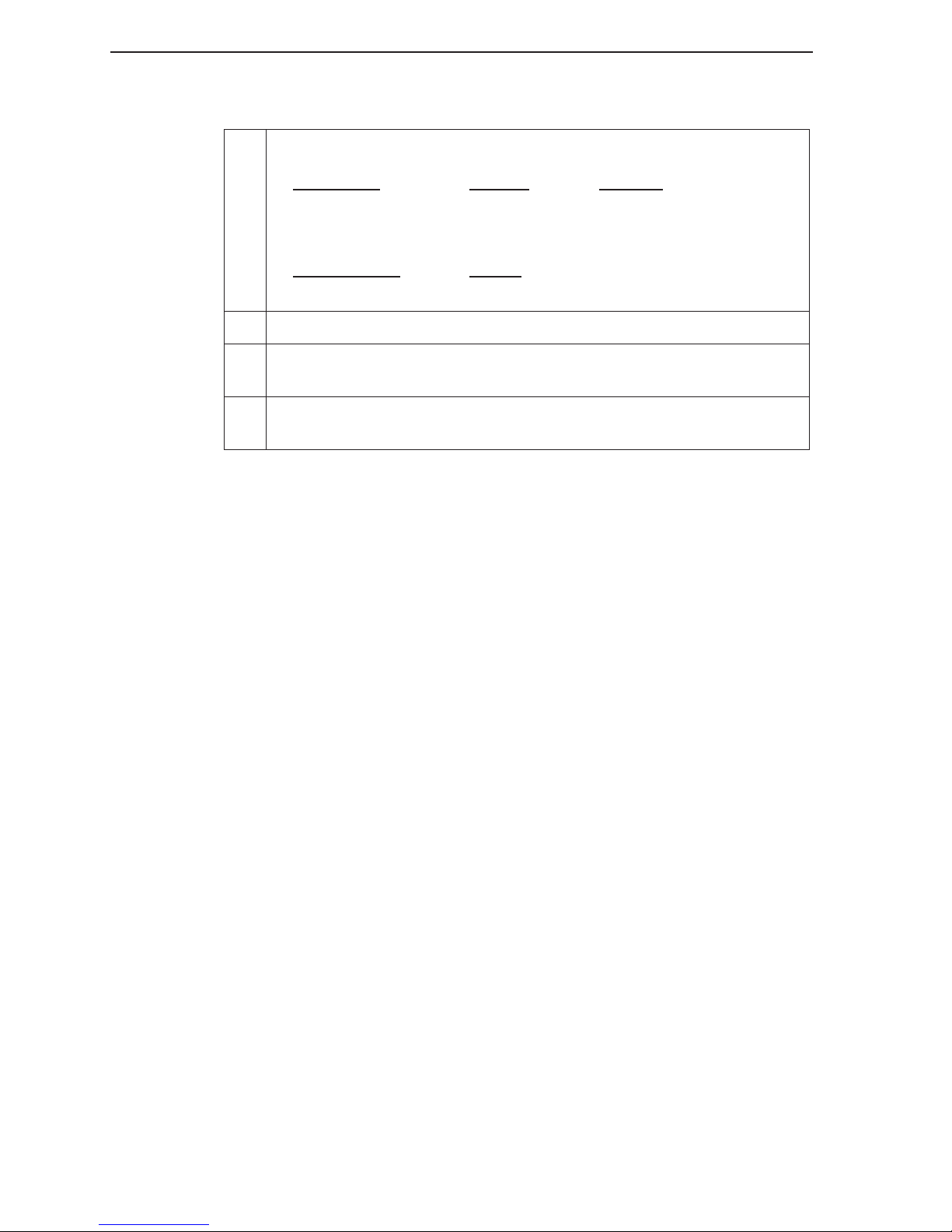
Prepare 10x TBE as follows:
1. Add the following to a 1000 ml beaker:
Component
Amount Molarity
Tris Base 107.8 g 0.89 M
Boric Acid 55.0 g 0.89 M
EDTA (disodium salt) 7.4 g 0.02 M
Distilled w
ater 950 ml
TOTAL VOLUME 1000 ml
2. Stir to dissolve. Bring to a final volume of 1000 ml.
3. Check the freshly prepared 10x TBE to make sure that it has a pH of 8.3
at 25 °C.
4. Store at room temperature. Note that some precipitation may occur during prolonged storage.
Preparing Ammonium Persulfate Solution
APS provides a source of free radicals needed for polymerization of the gel
(Sambrook, 1989). A 10% APS solution is made by adding 0.1 g APS to 1.0 ml
deionized water in a small test tube. Prepare APS daily to ensure a fresh
working solution. "Stale" APS will adversely affect band quality and give bands a
“fuzzier” appearance with less distinct edges.
2-8
Page 17
Gel Preparation and Electrophoresis
Acrylamide
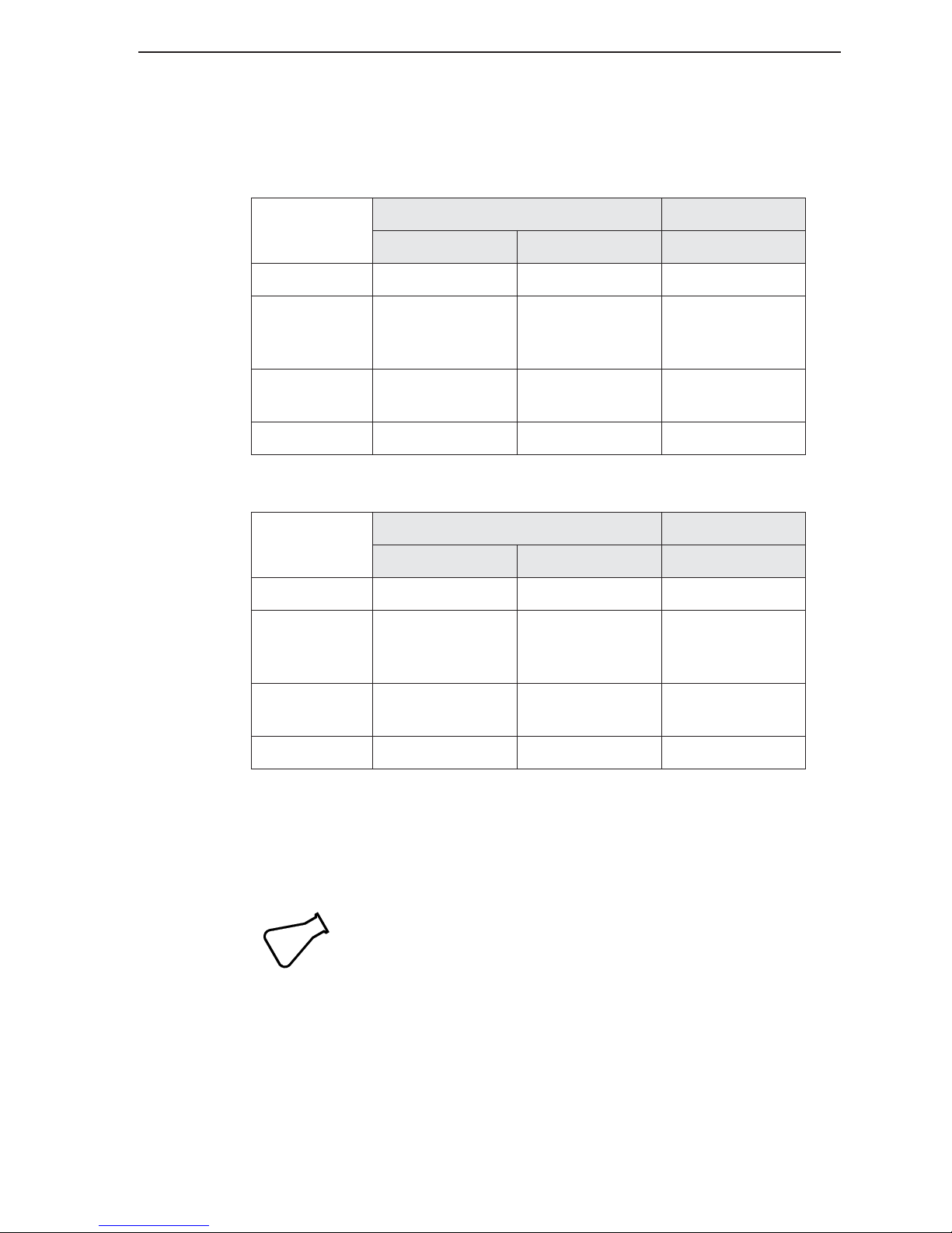
The tables below give examples for mixing gel solutions:
Long Ranger™ Gel Components
41 cm 18 or 25 cm
0.25 mm, 6% 0.20 mm, 5.5% 0.25 mm 6.5%
Urea (7M) 12.6 g 12.6 g 8.4 g
50% Long
Ranger™
acrylamide
10X TBE
buffer
dd water to 30.0 ml to 30.0 ml to 20 ml
Page Plus™ Gel Components
Urea (7M) 12.6 g 12.6 g 8.4 g
40% Page
Plus™ acrylamide
10X TBE
buffer
dd water to 30.0 ml to 30.0 ml to 20 ml
3.6ml 3.3 ml 2.6 ml
3.0 ml 3.0 ml 2.0 ml
41 cm 18 or 25 cm
0.25 mm, 6% 0.20 mm, 5.5% 0.25 mm 6.5%
4.5 ml 4.125 ml 3.25 ml
3.0 ml 3.0 ml 2.0 ml
A number of other commercial acrylamides can be used to cast gels for the
LI-COR system including RapidGel-XL (USB) and Sequagel (National
Diagnostics).
Tip
To mix the gel solution in one beaker: Place a 100 ml beaker with a
stir bar on a balance and tare the balance. Measure 12.6 grams of
urea into the beaker, then add the acrylamide solution and 10x TBE
buffer. Add dd water to target volume of 30 ml gel solution).
2-9
Page 18
Section 2
Mixing the Gel Solution
1. Mix well at room temperature and filter the solution using a membrane
filtration system (syringe top or bottle top from any supplier).
2. Add 150 µl of 10% APS per 20 ml of gel solution and swirl gently.
3. Just before pouring, add 15 µl TEMED. You have approximately 3-5
minutes to pour the gel before it polymerizes.
Pouring a 6.5% KB
The following items are required to pour the gel:
• 20 ml of 6.5% KB
•KB
• 150 µl of 10% Ammonium persulfate (APS)
• Comb
• 60 cc syringe with 14 gauge tip
• Pasteur pipette
• Assembled gel sandwich and casting stand (optional)
• 15 µl of TEMED
1. Bring 20 ml of KB
2. Add 150 µl of 10% APS and 15 µl TEMED when ready to inject gel
3. Mix to homogenate and draw the gel solution into a 60 cc syringe with
Plus
1X TBE buffer (recommended for use with KB
glass plates for gel injection while KB
solution.
14 gauge tip.
Plus
Plus
Plus
Gel
Gel Matrix for Genotyping
to room temperature (10-15 minutes) and prepare
Plus
warms.
Plus
gel matrix)
2-10
Page 19
Gel Preparation and Electrophoresis
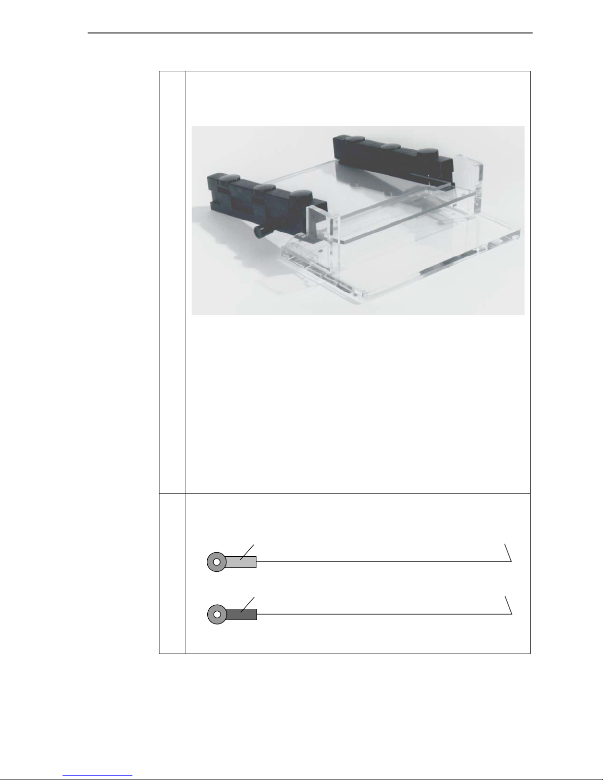
4. For 25 cm gels, a notch on the back of each rail that allows the apparatus to rest on the uppermost metal posts on the casting stand (Figure 2-6).
This slight incline improves the flow of the gel between the plates.
Figure 2-6. Rest the apparatus on the casting stand (25 cm plates).
Start a little above the bottom of the notch at the left or right side of the
notch in the front plate. Inject the gel evenly at a steady rate while moving downward to the bottom of the notch and then side to side across
the notch. Periodically tap the front of the plates firmly to prevent the
formation of air bubbles. If the gel is being injected correctly, you
should get a smooth half moon shaped gel front advancing downward
between the gel plates. If plates are dirty, the advancing primer front
will be jagged. Never pull up the syringe after you start injecting. Any
time you stop you are likely to create an air bubble. When the gel solution reaches the bottom of the plates and a small pool of gel overflows
onto the notch in the front plate, quickly lay the plate assembly flat on
the bench to prevent the gel solution from running out the bottom.
5. Remove any bubbles that form during gel pouring using a bubble hook
(Figure 2-7).
Yellow: 0.25 mm diameter
Blue: 0.20 mm diameter
Figure 2-7 . Bubble Hooks.
2-11
Page 20
Section 2
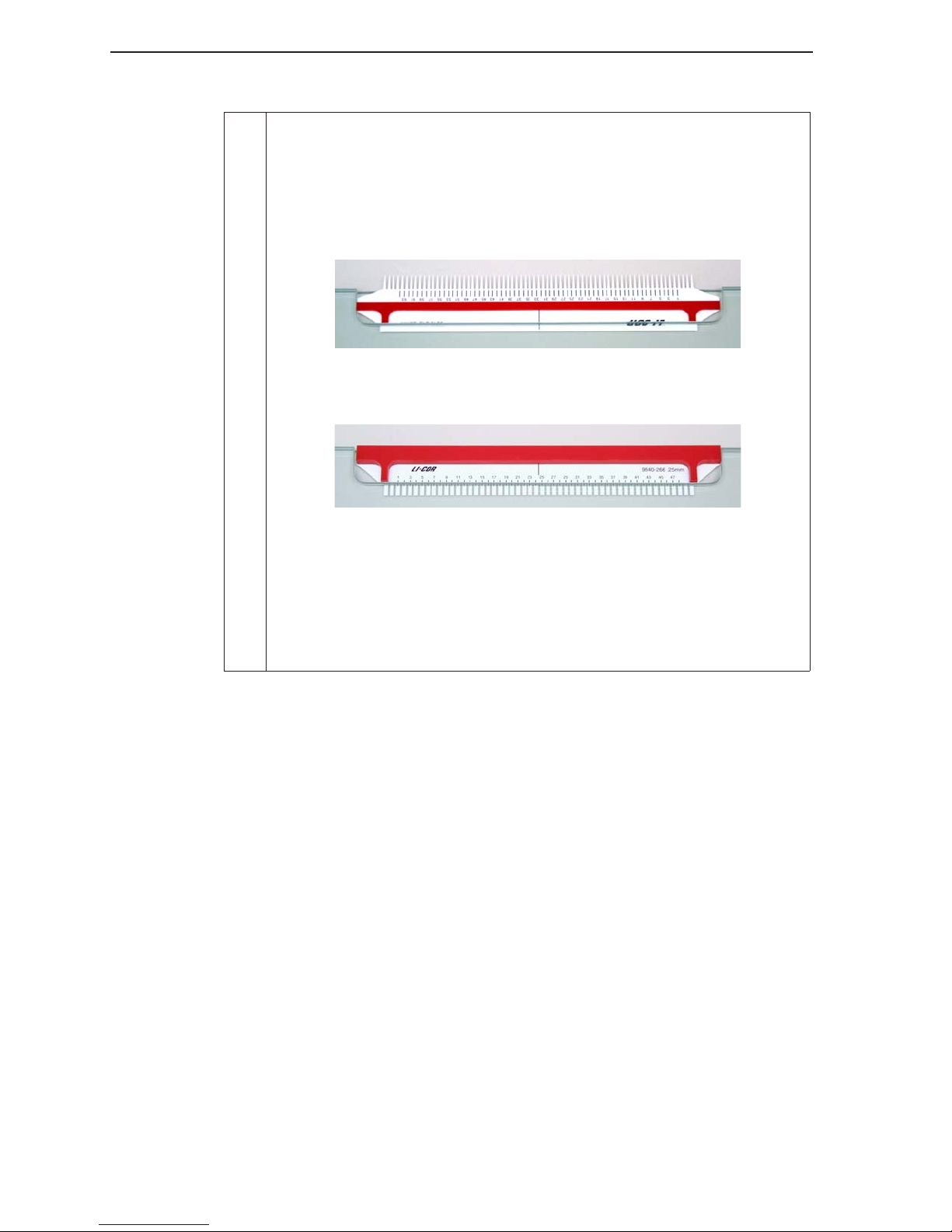
6. Insert the comb. Figures 2-8 and 2-9 show how to insert the mylar
sharkstooth and rectangular tooth combs after pouring the gel. Instructions for inserting paper combs are given in the Appendices (Section 5).
The sharkstooth comb is inserted upside down during polymerization to
make a trough which forms the base of the wells, and is then inverted
before loading the samples.
Figure 2-8 . Center the comb in the notch and insert the
sharkstooth comb upside down until the plastic depth
gauge rests on top of the notch.
Figure 2-9 . Center the comb in the notch and insert the
rectangular tooth comb with the teeth downward, until the
plastic depth gauge rests on the notch.
Insert the comb slowly to avoid air bubbles forming around the comb.
Air bubbles can destroy or deform the wells. Add a small amount of the
gel solution over the comb (near the notch) to compensate for gel
shrinkage as it polymerizes.
2-12
Page 21
Gel Preparation and Electrophoresis
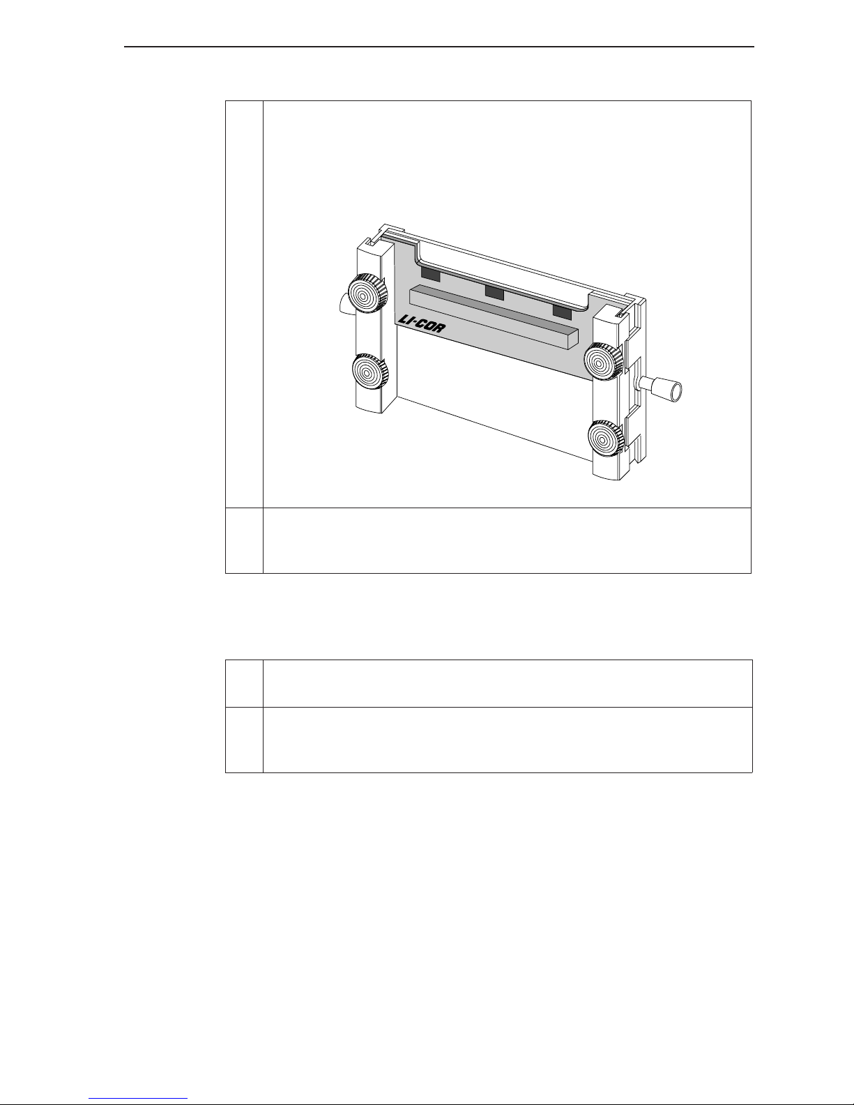
7. Place the casting plate into the grooved area in the rails normally
occupied by the upper buffer tank. Tighten the two tank clamp knobs
until finger tight. Alternatively, the upper buffer tank (with gasket) can
be used in place of the casting plate. If you insert the upper buffer tank,
be careful not to spill gel solution into the tank during gel pouring.
®
CASTING PLATE
Figure 2-10. Insert the casting plate and tighten the knobs.
8. Allow the gel to polymerize for at least 1 hour before use. Check the
tightness of the clamp knobs after polymerization to make sure they are
still tight.
Pre-electrophoresis Preparation
1. After the gel has polymerized, loosen the upper knob on each rail and
remove the casting plate.
2. Add a small volume of water to the notched area on the front plate
where the comb is inserted. When the comb is removed water will be
drawn into the wells, which helps to maintain good well morphology.
2-13
Page 22
Section 2
3. Remove the comb:
Rectangular tooth comb: Carefully remove the comb by slowly
pulling it straight out. This is a critical step, in that the well
morphology must be maintained for sample loading. If the comb
does not slide out easily, it may help to use a razor blade to score
along the edge between the top of the comb and the back plate to
break the gel seal. Rinse the wells with TBE buffer using a 20cc
syringe fitted with a 22 gauge needle.
Sharkstooth comb: Hold a razor blade at a 45° angle relative to the
comb and lightly score the acrylamide along the interface between
the glass and the plastic comb. This will prevent acrylamide from
cracking off and dropping into the well. Carefully remove the comb
from the gel and rinse the single well with TBE buffer using a 20cc
syringe fitted with a 22 gauge needle. Be sure to remove any small
acrylamide fragments in well. Proceed with gel clean-up before reinserting the comb.
4. After removing the comb, use a razor blade to remove excess gel from
the inside of the back plate above the notched area where the comb
was previously inserted. Similarly, remove any gel from the outside of
the plates, at the bottom and top of the gel sandwich, and next to the
rails on the back plate.
5. Use wipes and deionized water to clean the back and front plates, then
100% isopropanol (optional). The area on the plates (between the two
bottom knobs) corresponding to the position of the sequencer's scanning window is the most important and should be carefully cleaned.
6. If using a sharkstooth comb, re-insert the comb until the teeth just touch
the gel. Hold the gel upright against a good light source in order to see
the bottom of the well. (A casting stand is useful for this.)
Lightly coat the teeth of the sharkstooth comb with Cello-
Tip
Seal (Fisher #C-601) to help seal the wells and hold the
comb in place.
7. Press the white rubber gasket into the recessed groove on the back of
the upper buffer tank. Do not stretch the gasket while pressing it into
place. (Note: Do not use alcohol to clean this gasket - use only water).
8. Loosen the upper clamp knob on each rail and slide the upper buffer
tank into place. Be careful not to let the gasket touch or drag against the
plates while installing the tank, as this may pull the gasket from its
position in the groove. If the gasket is displaced from the groove, buffer
will leak from the upper tank during electrophoresis. For new gaskets,
you may need to carefully wet plate near the gasket and rub water over
the gasket with your fingers (only necessary the first 4-5 times a gasket is
used). Don’t let water contact the rails or run down the front plate.
2-14
Page 23
Gel Preparation and Electrophoresis
9. Tighten the upper clamp knobs "finger tight". The electrophoresis apparatus is now fully assembled.
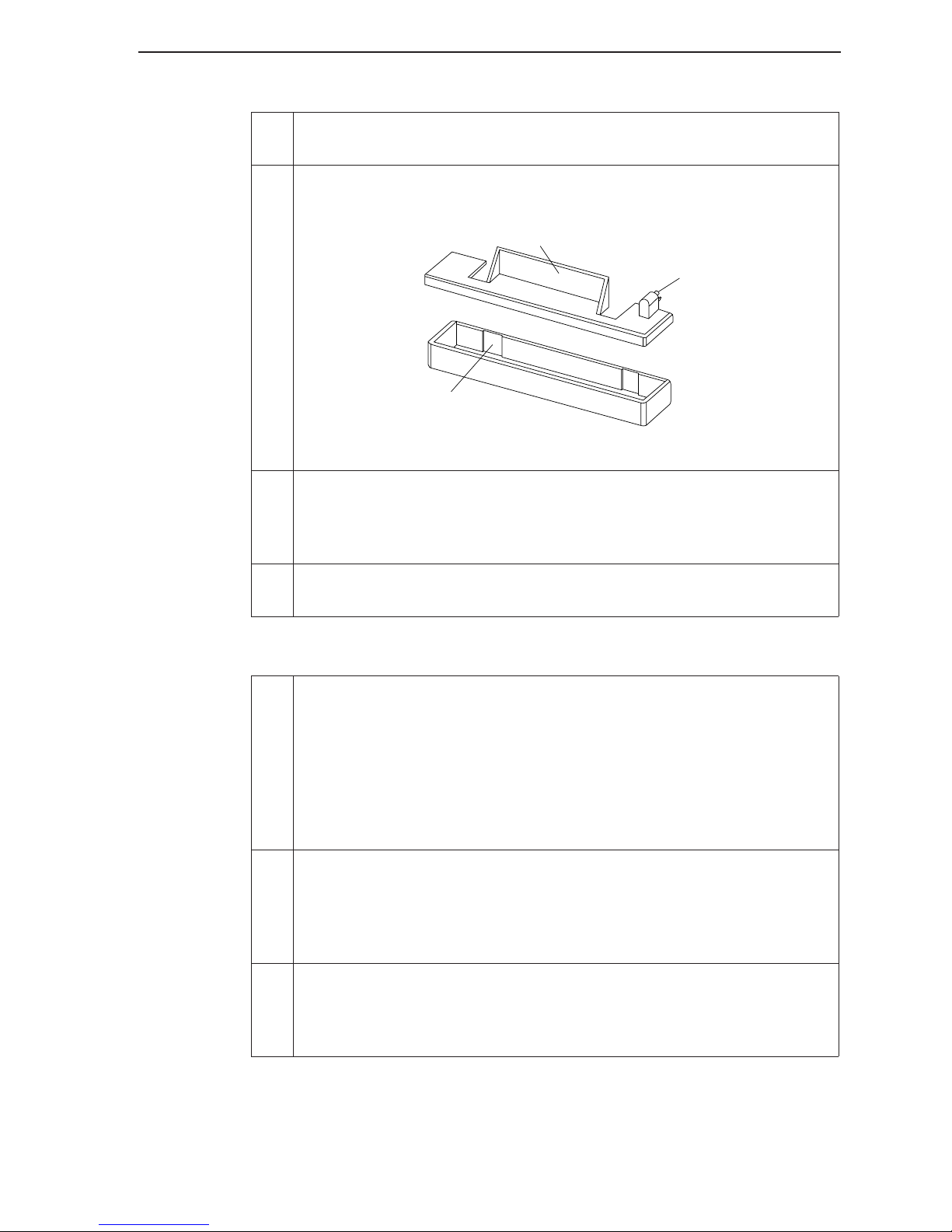
10. Open the instrument door and place the lower buffer tank into position
at the base of the heater plate. The tank has two recessed areas where
the rails rest when the assembled gel apparatus is installed.
Shield
High Voltage
Connector
Recessed Area
Figure 2-11. The side of the lower buffer tank with
the recessed areas is placed against the heater plate.
11. Mount the gel apparatus on the instrument against the heater plate, with
the bottom of the gel sandwich inside the lower buffer tank. Check to
see that the support arms holding the gel assembly on the instrument
are seated evenly on the bracket.
12. Inspect the plates at the location of the scanning window to make sure
they are free of smears, dust, or spots that may interfere with detection.
Filling the Buffer Tanks
Plus
13. For KB
For other gel formulations use 10x TBE buffer stock solution to make
1000 ml of TBE running buffer. For example: To make 0.8x running
buffer for 0.2mm gels, measure 80 ml of 10x TBE buffer into a one liter
graduated cylinder and add dd water to 1000 ml. Seal the top of the
cylinder with Parafilm and invert the cylinder several times (carefully!)
to mix completely before filling the tanks.
14. Fill the upper buffer tank to the Max Fill line. Do not fill past the Max
Fill line. Pour the remainder of the buffer into the lower buffer tank.
(Pour to the left of the left rail.) The level of buffer solution must be high
enough to immerse the platinum electrodes (attached to the tank lids),
so power can be applied to the gel.
15. Fill a 20cc syringe with buffer from the upper tank, add a 22 gauge
needle and flush the wells with buffer to remove crystallized urea and
air bubbles. Be careful not to dislodge the teeth when flushing wells
around the sharkstooth comb.
gels, use 1X TBE running buffer (see Gel Preparation).
2-15
Page 24
Section 2
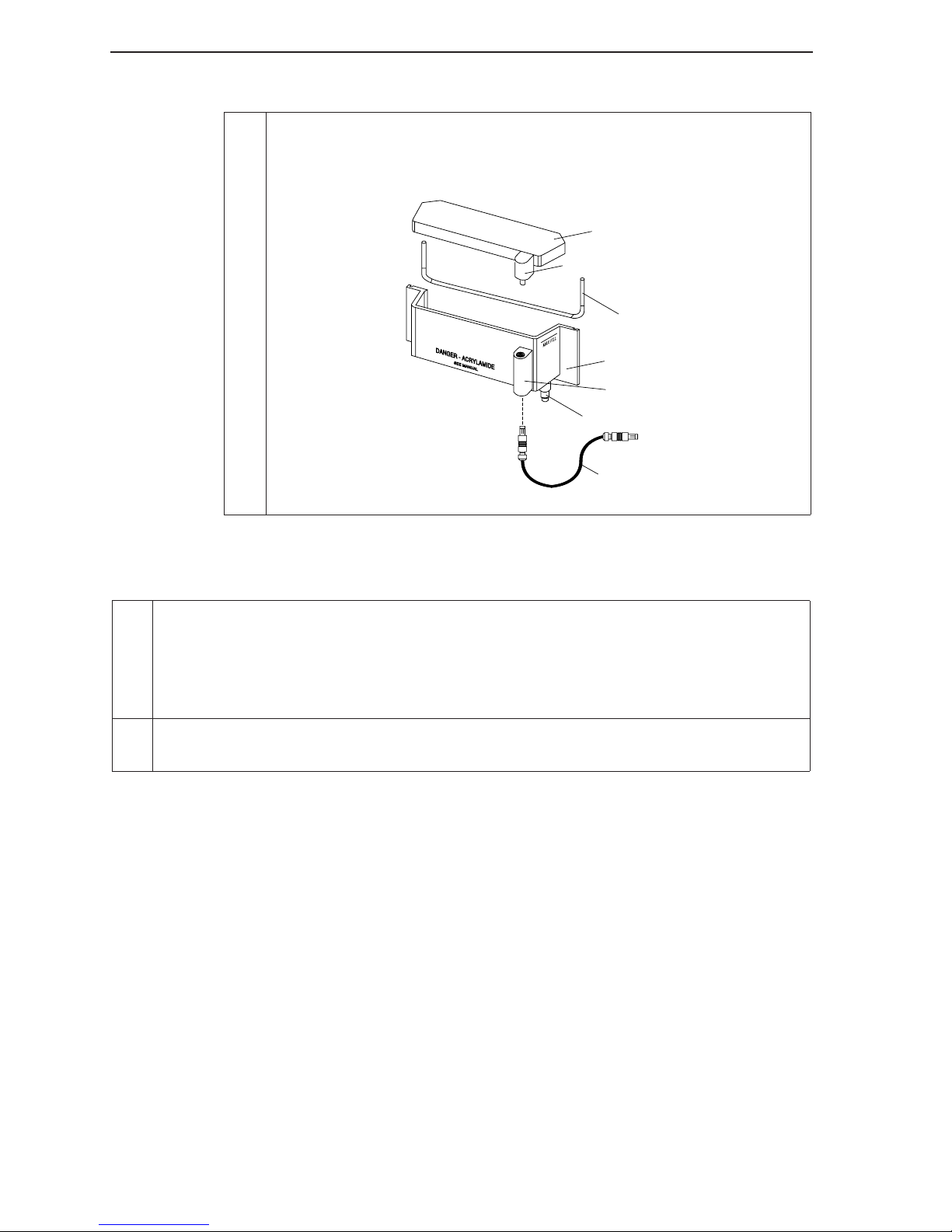
16. Place the upper and lower buffer tank lids onto the tanks. Insert the
power cable on the upper buffer tank and connect it to the high voltage
connector on the instrument chassis, as shown in Figure 5-14. Make
sure that both connectors are fully inserted.
Upper buffer
tank lid
High voltage connector
Gasket
Upper buffer
tank
High voltage
connector
Drain fitting
To chassis
Jumper
Figure 5-14. Upper buffer tank connections.
1.
Pour approximately 500 ml of KB
Plus
1X TBE running buffer (see Gel Preparation above)
into both the upper and lower tanks. Do not fill past the Max Fill line on the upper tank.
Pour the buffer to the left of the left rail in the lower tank. The level of buffer solution
must be high enough to immerse the platinum electrodes (attached to the tank lids), so
power can be applied to the gel.
2. Flush the wells with a 20cc syringe to remove any urea or other particulate matter. Be
careful not to dislodge the teeth when flushing wells around the sharkstooth comb.
2-16
Page 25
Gel Preparation and Electrophoresis
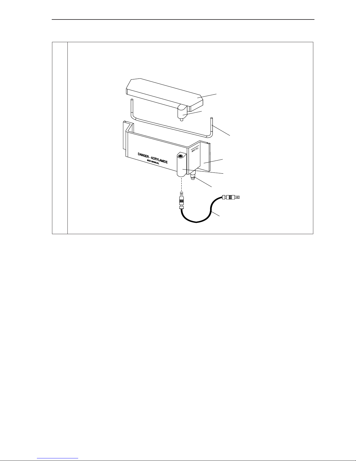
3. Place the upper and lower buffer tank lids onto the tanks. Insert the jumper on the
upper buffer tank and connect it to the high voltage connector on the instrument chassis, as shown below. Make sure that both connectors are fully inserted.
Upper buffer
tank lid
High voltage connector
Gasket
Upper buffer
tank
High voltage
connector
Drain fitting
To chassis
Jumper
Figure 2-11. Upper buffer tank connections.
2-17
Page 26
Section 2
Starting Runs
Pre-electrophoresis and electrophoresis can be started using, SagaGT
Microsatellite Analysis Software, Saga Lite Electrophoresis Software, or through
the browser interface of the DNA analyzer. Information on starting runs can be
found in the following places:
GT
• Saga
: SagaGT Tutorial Manual and SagaGT User Guide
• Saga Lite: Saga Lite help system
• Browser Interface: Model 4300 Operator’s Manual.
These manuals also discuss the procedure for reloading gels. Starting runs on
reloaded gels is different because the pre-run is not necessary.
Sample Loading
Materials required: 20 cc syringe with 25 gauge tip.
1. Denature samples at 94 °C for 3 minutes. After 3 minutes, immediately
put the samples on ice and cover to reduce exposure to light.
2. Open the instrument door and remove the upper buffer tank lid.
Remove particulate matter by flushing the wells with running buffer
using a 20 cc syringe.
3. For a 0.25 mm gel, load with the 8-channel 0.2 mm Hamilton syringe or
a pipette with flat 0.2 mm micropipette tips.
4. Carefully position the tip(s) between the glass plates and slowly release
the mixture into the wells. Load up to 1.0 µl per well depending on comb
size and gel thickness.
Loading Tips:
• Do not load wells that are deformed or contain air bubbles that cannot be removed.
• Do not overload the wells – samples could flow into adjoining wells.
• Avoid injecting an air bubble into the well after the sample is loaded, as this can
force the load into adjoining wells.
• When loading rectangular tooth combs with a single pipette, flush four or five
wells, load them, and repeat. If you waiting too long after flushing the wells, urea
will leach into the wells and makes them even more transparent.
• One of the accessories for the Model 4300 is a well visualization aid that can help
you see rectangular wells. This aid has a mylar sheet that slides in behind the rear
plate and can make the wells more visible. Don’t forget to remove the visualiza-
tion aid before electrophoresis.
• One way to visualize rectangular wells is to look for the reflection of the wells in
the upper surface of the notched front plate. Load by putting the tip in so it touches
the back plate, then down slightly.
5. After sample loading, replace the upper buffer tank lid (Figure 2-11),
close the instrument door, and start the run using Saga
software.
2-18
GT
or the browser
Page 27
Disassembly
1. Remove the buffer tank lids.
2. For 18 cm gels, remove the entire gel apparatus from the instrument
and carefully dispose of the buffer solution.
3. For 25 cm or larger gels, the upper buffer tank has a fitting for draining
the buffer solution, while the apparatus is still secured to the instrument.
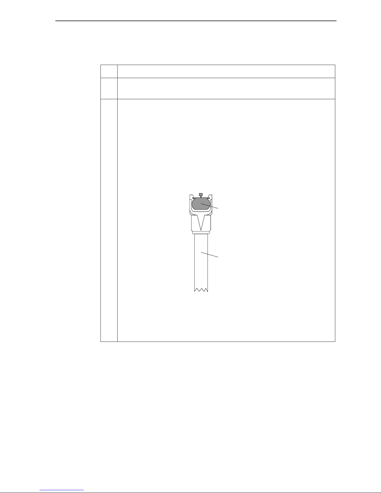
A coupling attached to a length of gum rubber tubing is provided to
facilitate draining the tank (Figure 2-12). Make sure the tubing is placed
in a proper receptacle, as buffer will begin to drain immediately upon
connection of the coupling.
Insert the coupling until it snaps into place.
Gel Preparation and Electrophoresis
Press here to release
Rubber tubing
Figure 2-12. Buffer tank drain fitting.
Depress the metal ring on the coupling and pull straight down to
remove the drain hose when finished.
2-19
Page 28
Section 2
Cleanup
1. After removing the upper and lower buffer tank lids and disconnecting
2. Remove the lower buffer tank and dispose of the buffer solution.
3. Rinse the rails, spacers, and comb, and allow to air dry.
4. Rinse and air dry the upper and lower buffer tanks and lids.
5. Clean any spills on the heater plate, chassis, or front panel.
Cleaning the Plates
Materials needed:
the power cable, take the gel assembly off the sequencer and remove
the upper buffer tank and rails.
• 2% laboratory detergent solution made from a concentrate such as
Micro (International Products Corp., Burlington NJ), or Liquinox
(Alconox Inc., New York, NY).
• Spray bottle capable of spraying a fine mist, containing 70% ethanol.
1. A small black plastic wedge is included in the spare parts kit to aid in
separating the gel plates. Insert the wedge between the plates to pry
them apart for cleaning.
Caution: Do not pry on the left and right sides of the front plate where
the glass is narrow.
Never use metal tools to pry plates apart. Lab spatulas, razor blades, or
similar tools can chip plates.
2. Dispose of the acrylamide in compliance with your local regulations.
Try to clean gels within 1-2 hours after the run is complete. If the gel
has recently cooled to room temperature, acrylamide will adhere to
paper towels, which can be used to lift the acrylamide off the plates. If
gels have been left for more than 4 hours, use a razor blade to scrape
the acrylamide from the plates.
3. Pour a small amount (6 cm circle) of 2% detergent onto the side of the
plate that will contact the gel.
4. Work the solution into a lather with a nylon bristle brush and thoroughly scrub the entire plate. Remove any dried-on polyacrylamide
with a razor blade, if necessary. Rinse well with water.
2-20
Page 29

Gel Preparation and Electrophoresis
5. Pour distilled water onto the plate. Work the water around the plate
with a gloved hand and watch for bubble formation from detergent residue. Repeat until no bubbles form.
6. Repeat steps 3-5 above with the second plate.
7. Rinse the plate with deionized distilled water. Use a pump spray bottle
to spray a fine mist of 70% ethanol/ddH
O for a final rinse. Stand plates
2
in a rack to air dry.
2-21
Page 30

iii
Page 31

PCR Protocols
3
Section
dNTP Recommendation
We recommend using a dNTP mix containing 7-deaza-dGTP to minimize
anomalies in migration that may cause difficulties in band sizing. Stock dNTP
concentration is recommended to be 2 mM, whereas the concentration used in
each reaction is 2 nmol for up to 6 loci per reaction.
PCR Optimization
As with any PCR, IRDye-labeled primer pairs may require optimization.
Conditions employed in radioactive studies may need to be altered to be used
for fluorescently-labeled primers.
Primer Design Considerations:
1. Forward and Reverse primers should not be complimentary, especially at the
3' ends. The last six bases on the 3' end should be approximately 50% G+C,
with a G or C at the end if possible (no T's).
2. Primers should not be less than 17 bases long.
3. Primers should have a T
is T
(°C) = 2(#A + #T) + 4(#G + #C)
m
4. Primers should not have more than 4 consecutive bases of any one base.
5. No palindrome at the 3' end.
6. No stable hairpin loops at the 3' end.
Multiplexing Loci
If you need to design a screening set for an application, all loci should be
separated into groups according to allele size ranges, annealing temperature,
concentration requirements, and possible primer/dimer combinations.
MgCl
2
Markers that can be clearly separated on gels are placed in groups of three to six
loci. The remaining loci can be run in groups of two or individually if needed.
Generally three markers can be multiplexed conveniently by either combining
greater than 60 °C. A general approximation for T
m
m
3-1
Page 32

Section 3
PCR reactions prior to loading the gel (pooling) or by including compatible
primer pairs in the same PCR reaction (single tube).
When selecting compatible primer pairs, the size range of the PCR products
(smallest and largest alleles) must be such that loci are adequately spaced
without overlap. Choose each locus range generously and allow 10-12 bp
between adjacent locus ranges.
Pooling
When reactions are pooled, each primer pair can be run under optimum PCR
conditions without making compromises in PCR that would decrease yields.
Separate PCR reactions produce fewer nonspecific amplification products in
comparison with multiplexing in single tube reactions. Also, with separate
reactions, the reaction volumes can be adjusted to avoid band saturation for
strong reactions, or to increase signal intensity for weak reactions. Saturated
bands decreases accuracy when bands are sized. The disadvantages of pooling
separate reactions are the additional reagent costs, labor and pipetting time.
Single Tube Reactions
Multiplexing will require some optimization, and the final conditions may not
be optimal for all primer pairs. For example, the Marshfield Clinic web site
(http://www.marshfieldclinic.org/research/genetics/) provides information on
multiplexing primer pairs for various screening sets. Multiplexed reactions
reduce pipetting steps and save on reagent costs, but may require more primer
to yield the same band intensity. Since the amount of primer provided is usually
more than adequate to complete even a large study, these advantages may justify
the effort required to define conditions for multiple primer sets in single tube
reactions.
Microsatellite Optimization
There are four considerations when optimizing thermocycling and reaction
conditions for amplifying microsatellites: 1) primer amount; 2) MgCl
concentration; 3) T
be simultaneously addressed for optimum results.
Primer Amount
; and 4) DNA concentration. All four considerations should
m
2
Microsatellite primers have an inherent "quality" due to their base composition,
primer length (ideal length is 20-24 bases), GC clamp (the last 6 bases should be
50% GC ), salt requirements, T
multiplex (multiple loci amplified in the same tube) reactions, primer-dimers,
etc. This "quality" results in the need to use varying amounts of primer to amplify
a particular locus and obtain an acceptable signal intensity. In multiplex
reactions, one primer set may need only 55 fmol of each primer, whereas
3-2
, primer-to-primer interactions in monoplex and
m
Page 33

PCR Protocols
another may need 1.1 pmol to achieve the same band intensity. Even in
monoplex reactions, a few primers may need 2-10 pmol of primer to achieve
optimal results. These primers have relatively poor quality and should be
redesigned if possible.
To begin optimization, start the initial amplification with 0.1 to 0.5 pmol of
primer for either monoplex or multiplex conditions. If you want to multiplex a
group of primers, the initial optimization should be performed as a multiplex
reaction – the conditions used in a monoplex reaction may not be maintained in
a multiplex reaction due to primer-primer interactions, primer-template
interactions, competition for dNTP's, M13 primers, etc.
If M13 primers are used for the “M13 tailed primer protocol”, start with 0.3
pmol of primer (work up to 1.0 pmol). See Tailed Primers protocol on page 3-9
in this section.
If bands on the electrophoresis image look fuzzy or smeared, too much primer
has been used. Dilute the reaction with stop buffer before loading or load a
smaller amount. If this does help, decrease the primer concentration by 50%
and reamplify. Primer concentration should also be reduced when excess nonspecific products are present, along with allele bands that are intense, but fuzzy
or smeared.
If there is no amplification, or very weak signal, check for a strong band at the
primer front, which indicates non-incorporated primer. In this case, make sure
that all
sequence is correct. Also check the T
the range of the T
(or T
reagents are added to the reaction. If this is true, make sure the primer
and make sure the cycling program is in
m
(a good starting point is 3 degrees below the theoretical T
m
)). If there are weak bands and weak or no primer front, double the primer
a
m
concentration and continue until the signal is seen. Increase the concentration
up to 10 pmol if needed.
MgCI
Most loci can be amplified using 1.5 to 2.0 mM of MgCl
Concentration (ranges from 1.0 to 4.0 mM)
2
. If you have poor
2
results after running different primer concentrations with 1.5 to 2.0 mM of
MgCl
3.5 mM and 4.0 mM. Using MgCl
reduce the need to optimize MgCl
T
, set up reactions using 1.0 mM, 1.5 mM, 2.0 mM, 2.5 mM, 3.0 mM,
2
tolerant polymerases, such as Tfl, may
2
.
2
(ranges from 48 °C to 60 °C)
m
Monoplex Reactions: Most loci can be amplified using standard thermocycling
parameters with the annealing temperature set in the range T
the annealing temperature (T
down to T
- 5 °C, though the result may increase the amount of non-specific
m
)). For some primers, it may be necessary to go
a
m
to T
m
- 3 °C (i.e.,
amplification products.
3-3
Page 34

Section 3
Multiplex Reactions: For multiplexing, the "touchdown" protocol (54 °C High
Temperature Enhanced) allows you to mix primer sets that vary widely in T
m
. A
"touchdown" protocol starts with a series of decreasing annealing temperatures
for several cycles (usually decreasing1-2 °C per cycle for 5-10 cycles). These
initial cycles allow primers with higher annealing temperatures to start
amplifying before primers with lower melting temperatures. The final cycles (25-
35) are performed near the lowest T
. With this protocol, higher T
m
primers are
m
given an early start, thereby producing a series of highly specific products. These
products "overwhelm" any non-specific products that may be produced at the
lower annealing temperatures. The primers in the multiplex with lower
annealing temperatures amplify as they would in the standard thermocycling
protocol.
When the results are not satisfactory under standard conditions, test each primer
separately in reactions varying the following conditions:
+2
1. [Mg
2. Annealing temperature (determined from T
]: Test 1.5 mM, 2 mM, 2.5 mM, 3.0 mM, 3.5 mM and 4.0 mM.
of both primers). Refer to the
m
Appendices for calculation of T
.
m
3. Standard PCR methods vs "touchdown" methods.
Template DNA Amount
20-50 ng of DNA is recommended for genotyping, although as little as 5 ng of
DNA can be used with primers of average to high quality. For primers of normal
to lower quality, up to 50 ng of DNA may be necessary. For multiplexing, it is
normally not necessary to use more than 50 ng of DNA total in the same
reaction. As with any amplification of genomic DNA, purity should be 1.7 to 2.0
(spectrophotometrically determined 260nm/280nm ratios).
Lab Organization
Any lab performing routine PCR reactions should consider the potential for
contamination. Laboratories performing PCR on a regular basis generally
establish three separate stations: template isolation, a pre-PCR area and a postPCR area. We strongly recommend this system. It is preferable that the stations
be in separate labs, though this may not always be possible due to space
limitations. If stations are in the same lab, separate the pre-PCR and post-PCR
areas as much as possible. In the protocol below, the PCR reaction is (if possible)
prepared in an isolated pre-PCR hood with UV lighting. The use of UV lighting
will eliminate any cross contamination from previous samples. If possible, the
thermocycler(s) and the DNA analyzer should be in a second location to reduce
the chance of post-PCR contamination in subsequent samples.
3-4
Page 35

Preparing Genomic DNA
DNA Quality
Most DNA preps will work, but as with all PCR, the DNA should have a 260/
280 ratio of 1.7 or greater. If the DNA was isolated from blood, the heme group
can inhibit the DNA polymerase if not removed.
DNA and Primer Amounts
The amplification reactions can be approached in two ways, depending on the
availability of DNA and the laboratory budget for primers. If primer cost
conservation is critical, reactions can be run with higher amounts of DNA (2050 ng) and lower primer amounts (>0.5 pmole). The protocols in this manual
were developed on this basis. Alternatively, if DNA is limiting, the PCR can be
run with significantly less DNA (2-5 ng) at the expense of higher primer amounts
(0.5 - 4.0 pmoles), depending on the quality of the primer reactions. In either
case, the best data will require optimization for each new primer pair. Note that
the quantity of DNA must be uniform for proper optimization.
PCR Protocols
Size Standards
Size standards are composed of IRDye-labeled DNA fragments with equal
banding intensities in 90% formamide solution with bromophenol blue. The
fragment sizes were selected to allow rapid identification of bands and accurate
fragment sizing over the entire range. The fragments cover the size ranges of 50
to 350 bp and 50 to 700.
Description # Lanes Dye Cat. Number
700 bp Size Standards
700 bp Size Standards 125 IRDye 800 4000-45
700 bp Size Standards 2500 IRDye 700 829-05345
700 bp Size Standards 2500 IRDye 800 829-05346
350 bp Size Standards 125 IRDye 700 4200-44
350 bp Size Standards 125 IRDye 800 4000-44B
350 bp Size Standards 2500 IRDye 700 829-05343
350 bp Size Standards 2500 IRDye 800 829-05344
The following concentrated size standards are also available.
Description Volume Dye Cat. Number
350 bp Size Standards
350 bp Size Standards 500 µl IRDye 800 829-06158
125 IRDye 700 4200-60
500 µl IRDye 700 829-06157
3-5
Page 36
Section 3
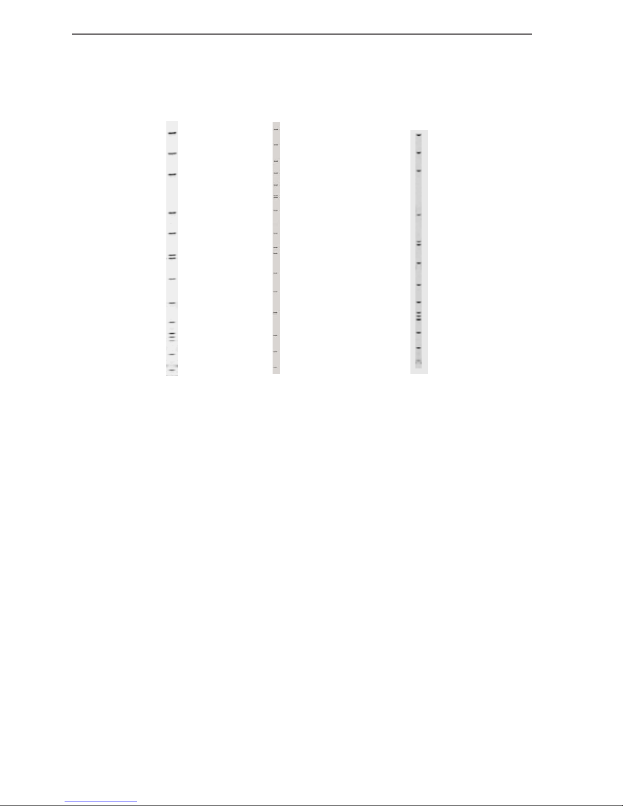
The fragment sizes are listed below:
50 - 350 Size
Standard
Size (bp)
350
325
300
255
50 - 700 Size
Standard
Size (bp)
700
650
600
565
530
500, 495
460
Concentrated
50 - 350 Size
Standard
Size (bp)
350
325
300
240
230
204, 200
175
145
120
105, 100
94
75
50
Figure 3-1. Fragment sizes for
50-350 and 50-700 size standard
sets.
400
364
350
300
255
204, 200
145
100
50
204, 200
175
145
120
105, 100
94
75
50
Figure 3-2. Fragment sizes for
the concentrated 50-350 size
standard set.
Precautions
The IRDye-labeled DNA should be stored in the dark at -20 °C. For best
performance, exposure to light should be minimized.
3-6
Page 37
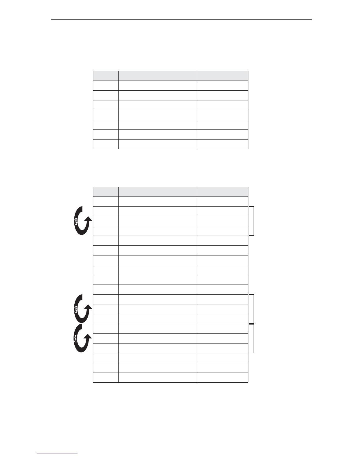
Cycling Programs
1. Standard
PCR Protocols
Step
Temperature (°C) Time
1. 95 5 minutes
2. 95 20 seconds
3. 55* 20 seconds
4. 72 30 seconds
5. 72 3 minutes
6. 4 hold
7. end
* Note: Annealing temperatures will alter depending on the T
2. 54 °C “Touchdown” PCR
Step Temperature (°C) Time
1. 95 5 minutes
2. 95 45 seconds
3. 68 °C minus 2°C/cycle* 5 minutes
4. 72 1 minute
5. 95 45 seconds
of the primers used.
m
5 cycles total
6. 58 2 minutes
7. 72 1 minute
8. 95 45 seconds
9. 56 2 minutes
10. 72 45 seconds
11. 95 45 seconds
12. 54 2 minutes
10 cycles total
13. 72 1 minute
14. 95 45 seconds
15. 54 ** 2 minutes
23 cycles total
16. 72 1 minute
17. 72 10 minutes
18. 4 hold
19. end
* Annealing temperatures are 68, 66, 64, 62 and 60, respectively, for the five cycles.
** Or, lowest annealing temperature of primers used.
3-7
Page 38
Section 3
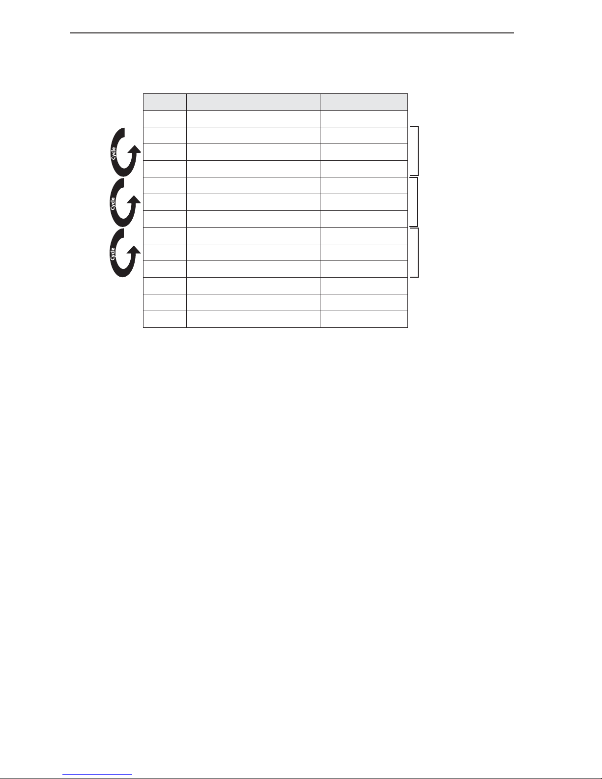
3. 47 °C “Touchdown” PCR
Step Temperature (°C) Time
1. 95 5 minutes
2. 95 45 seconds
3. 68 °C minus 2°C/cycle* 5 minutes
5 cycles total
4. 72 1 minute
5. 95 45 seconds
6. 54 2 minutes
11 cycles total
7. 72 1 minute
8. 95 45 seconds
9. 47 2 minutes
24 cycles total
10. 72 1 minute
11. 72 10 minutes
12. 4 hold
13. end
* Annealing temperatures are 68, 66, 64, 62 and 60, respectively, for the five cycles.
3-8
Page 39
Tailed Primers
In this approach, one of the unlabeled STR primers is synthesized with an M13 forward or
reverse primer sequence on the 5'-end. An IRDye-labeled M13 Primer is included in the PCR
reaction. The M13 primer is added to the PCR product during the first few cycles of
amplification. The labeled M13 primer is incorporated in subsequent cycles, thus labeling the
PCR product. This method requires no purification prior to gel analysis.
Important:
modified minimum and maximum locus boundaries in Saga’s Locus Manager should be increased
by the length of the primer incorporated in the PCR product.
When using tailed primers to amplify a locus that will be analyzed with Saga
GT
, the
The M13 primer sequence can be used on both 800 and 700 channels. LI-COR M13 forward
and reverse primer sequences are as follows:
4000-20B Forward (-29)/IRDye 800-labeled Primer, 19-mer: 5' - CACGACGTTGTAAAACGAC - 3'
4000-21B Reverse/IRDye 800-labeled Primer, 20-mer: 5' - GGATAACAATTTCACACAGG - 3'
Protocol
1. Enter the Standard program on the thermocycler (given earlier in this Section).
2. Add 20-50 ng of genomic DNA to a microcentrifuge tube or a microplate well.
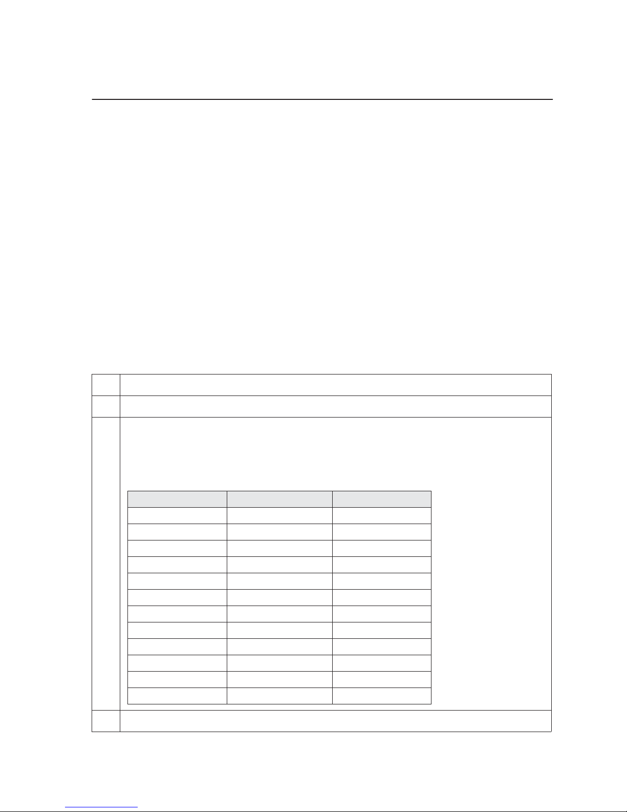
3. Determine the quantity of each component required using the following table, based
on the total number of reactions. Substitute water for the other primers if only a single
locus is being run. If MgCl
essary.
Component Stock Concentration Qty Per Reaction
10X Buffer 1.0
dH2O 3.3
dNTPs 2.0 mM 1.0
Primer 1fwd 1.0 pmol/µl 0.5
Primer 1rev 1.0 pmol/µl 0.5
Primer 2fwd 1.0 pmol/µl 0.5
Primer 2rev 1.0 pmol/µl 0.5
Primer 3fwd 1.0 pmol/µl 0.5
Primer 3rev 1.0 pmol/µl 0.5
M13f-29 primer 1.0 pmol/µl 1.0
Taq 5.0 unit 0.2
Total Volume 9.0 µl
is not premixed in the PCR buffer, account for MgCl
2
as nec-
2
4. Pipette gently to mix.
3-9
Page 40
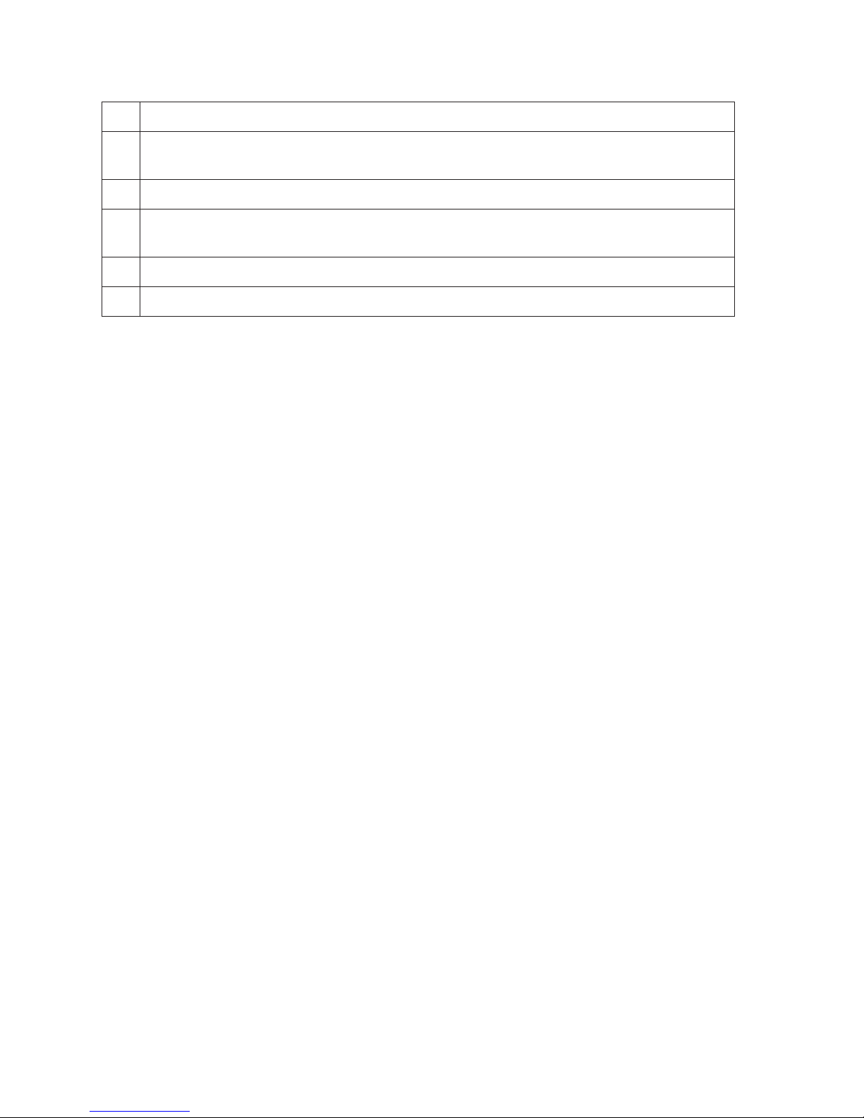
5. Add 9 µl of the STR mixture from above to each tube or well and pipette gently to mix.
6. If the thermocycler does not have a heated lid, add one drop of mineral oil to each
well.
7. Place the tubes or plate in the thermocycler. Start the cycling program.
8. After completion of the program, add 2 µl of stop buffer to each tube or well and mix
gently.
9. Heat samples at 95°C for 3 minutes and snap cool on ice before loading.
10. Load gel (volume depends on comb and gel thickness.
3-10
Page 41
Labeled Primers
One of the STR primer pairs can be synthesized with a 5'-IRDye label. In this manner one
strand of the resulting PCR product is labeled during amplification. The method is very robust
and no purification is required prior to gel analysis. Custom primers are available from LI-COR.
Protocol
1. Enter the Standard program, or a custom program on the thermocycler (given earlier in
this Section).
2. Add 20-50 ng of genomic DNA to a microcentrifuge tube or a microplate well.
3. Determine the quantity of each component required using the following table, based
on the total number of reactions. Substitute water for the other primers if only a single
locus is being run. If MgCl
essary.
Component Stock Concentration Qty Per Reaction
10X Buffer 1.0
dH2O 3.8
dNTPs 2.0 mM 1.0
Primer 1 labeled 1.0 pmol/µl 0.5
Primer 1unlabeled 1.0 pmol/µl 0.5
Primer 2labeled 1.0 pmol/µl 0.5
Primer 2unlabeled 1.0 pmol/µl 0.5
Primer 3labeled 1.0 pmol/µl 0.5
Primer 3unlabeled 1.0 pmol/µl 0.5
Taq 5.0 unit 0.2
Total Volume 9.0 µl
is not premixed in the PCR buffer, account for MgCl2 as nec-
2
4. Pipette gently to mix.
5. Add 9 µl of the STR mixture from above to each tube or well and pipette gently to mix.
6. If the thermocycler does not have a heated lid, add one drop of mineral oil to each
well.
7. Place the tubes or plate in the thermocycler. Start the cycling program.
8. After completion of the program, add 2 µl of stop buffer to each tube or well and mix
gently.
9. Heat the samples at 95°C for 3 minutes and snap cool on ice before loading.
10. Load gel (volume depends on comb and gel thickness.
3-11
Page 42

3-12
Page 43
Troubleshooting
Problem Cause Solution
Multiplexing
Not all loci amplify. Unamplified locus has lower
quality than others.
When using M13 tailed
primers, no loci amplify or a
weak signal is seen.
Reactions
Some tubes are empty after
cycling without oil.
One locus in a multiplex
reaction is very weak.
M13 labeled primer has
been exposed to light.
Caps are not sealing tightly. Seal caps only once.
Lower quality primer, suboptimal annealing temperature.
Choose different locus.
Increase primer concentration.
Replace with fresh primer.
Change tube suppliers to
match with cap supplier.
Switch to the CycleSeal Film
for sealing.
Needs higher concentration
of primer.
Need to alter annealing temperature or change to an
enhanced protocol.
A "smeared" band is seen
where the loci should be
visible.
A particular locus appears
"wavy" across the gel.
No bands appear,
consistently.
High primer concentration. Use primer with lower con-
centration.
High concentration of DNA. Reduce DNA concentration
and/or spectrophotometrically analyze DNA to keep
concentration between 2050 ng/reaction (no need to
increase concentration in a
multiplex reaction).
Possible overload. Reduce loading volume and/
or dilute samples.
Dinucleotide repeat of lower
MW that is not fully
resolved.
Degenerated primers. Try new primers.
dNTP’s are bad. Try dNTP’s with 7-Deaza.
Reload using 25-33 cm gel
plates.
3-13
Page 44
Problem Cause Solution
Bands in the 800 channel are
consistently weaker than the
IRDye 700 is more sensitive
than IRDye 800.
700 channel.
Bands are weak. Primer concentration too
low.
Mg concentration too low. Increase Mg concentration.
DNA concentration too low. Increase DNA concentration.
With the 800 image displayed,
select Alter Intensity from
the View menu in e-Seq and
adjust the image until the
bands are easier to see.
Increase primer concentration.
3-14
Page 45

Appendices
4
Section
T
Calculation
m
There are two different formulas presented below that can estimate the melting
temperature (T
will give a rough estimate. This estimate is based on the following:
4 °C for every G or C and 2 °C for every A or T.
) of a primer. The first is a very simple method (AT + GC)T
m
that
m
Example:
5'-TAC CTG GTT GAT CCT GCC AGT AG-3'
This primer is a 3-mer containing 12 G and C's, 11 A and T's. Therefore,
(12 × 4) + (11 × 2) = 48 +22 = 70 °C.
The second method (based on thermodynamic T
to the actual melting temperature and is the preferred formula. This method is as
follows:
69.3 °C + 0.41 x - 650/Primer length,
where x is the GC percentage.
Example:
Using the same primer shown above, the GC percentage is 52.2% and primer
length is 23 bases, so
69.3 °C + 0.41(52.2) - 650/23 = 69.3 + 21.4 -28.26 = 62.4 °C.
) results in a closer prediction
m
4-1
Page 46
Section 4
Calculation of Oligonucleotide Concentration (nmol) Given Optical Density (O.D.)
Some DNA synthesis laboratories will include the O.D. and possibly the
molecular weight (g/mol) with the primer that was synthesized. Others will
calculate the concentration and report it in nmol. To calculate DNA
concentration in nmol, both the O.D. and the molecular weight must be known.
If the molecular weight was not reported, it can be estimated by the following:
Each dATP = 313.21 g/mol
Each dCTP = 289.19 g/mol
Each dGTP = 329.21 g/mol
Each dTTP = 304.20 g/mol
Added to the calculation is 1 molecule of water (18.02 g/mol).
For example, the sequence 5'-GTA CTG ATT TAA TTC ACA TTT CCC-3' contains
6 A's, 10 T's, 6 C's, and 2 G's. Therefore,
A's 6 × 313.21 = 1,879.26 g/mol
T's 10 × 304.20 = 3,042.00 g/mol
C's 6 × 289.19 = 1,735.14 g/mol
G's 2 × 329.21 = 658.42 g/mol
Total molecular weight = 7,314.82 g/mol, plus 18.02 (one molecule of
water) = 7332.84 g/mol.
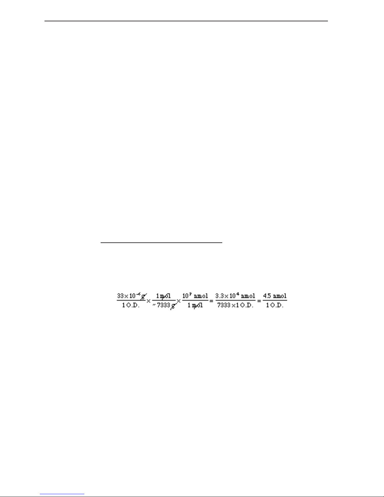
Since 1.0 O.D. is equal to approximately 33.0 µg, then if 1 O.D. of the
aforementioned oligo was synthesized, the calculation would be as follows:
Therefore, the synthetic oligo yield is 4.5 nmol, or 4,500 pmol. If 1.0 ml of TE
(10 mM Tris, 1 mM EDTA, pH 8.0) was added, the concentration would be
4.5 pmol/µl.
4-2
Page 47
Protocol for 96-well Paper Combs
Appendices
96 well paper sharkstooth combs are used for microsatellite, AFLP
genotyping applications. These combs are capable of being inserted, loaded,
and subsequently reloaded several
times without removal.
®
, and other
Protocol
1. After pouring the gel, invert the 0.25 mm casting comb to create a
trough that will form the bottom of each well.
2. After gel polymerization, remove the casting comb from the gel and
clean the single trough that was created. Use a small amount of water
and a razor blade to clean urea and gel debris from the trough area.
Remove the water in the trough by absorbing with a Kim Wipe
3. Mark the bottom of the trough with two dots from a Sharpie
help to identify the bottom when inserting the comb.
4. Add 1-2 ml of 1X TBE to the trough.
5. Insert the comb into the trough until the teeth just touch the gel. Use
the two dots from step 3 as a guide (Since the comb will swell as it
absorbs the buffer, placement of the comb should be completed in less
than 10 seconds).
®
.
®
. This will
6. Set up your gel for pre-electrophoresis, adding the 1X TBE buffer to the
upper and lower buffer tanks.
7. Pre-run your gel for the desired amount of time.
8. Using an 8-channel Hamilton syringe (optional), load samples. The
Hamilton syringe loads every 6th well as described in Section 1.
9. To re-load gels, stop electrophoresis, flush the wells (without removing
the comb), and load again. Note: Gel may not be reloaded after 6 hours
of its initial insertion.
4-3
Page 48

4647 Superior Street
International: 402-467-0700 • FAX: 402-467-0819
LI-COR GmbH, Germany (Serving Europe and Africa): +49 (0) 6172 17 17 771
LI-COR UK Ltd., UK (Serving UK, Ireland, and Scandinavia): +44 (0) 1223 422104
®
• P.O. Box 4000 • Lincoln, Nebraska 68504 USA
Technical Support: 800-645-4260
North America: 800-645-4267
www.licor.com
 Loading...