


50ct

Libretto 50CT/70CT Maintenance Manual i
Copyright
©1998 by Toshiba Corporation. All rights reserved. Under the copyright laws, this manual cannot be
reproduced in any form without the prior written permission of Toshiba. No patent liability is assumed with
respect to the use of the information contained herein.
Toshiba Libretto 50CT/70CT Maintenance Manual
Third edition February 1998
Disclaimer
The information contained in this manual is subject to change without notice.
Toshiba Corporation and Toshiba America Information Systems, Inc., assume no liability for damages
incurred directly or indirectly from errors, omissions, or discrepancies in connection with the furnishing,
performance, or use of this material.
Trademarks
IBM is a registered trademark, and PC/AT, PS/2, OS/2 and VGA are trademarks of IBM Corporation.
MS-DOS and Windows are registered trademarks of Microsoft Corporation.
Intel and Pentium are registered trademarks, and MMX is a trademark of Intel Corporation.
Lotus is a registered trademark of Lotus Development Corporation.
Novell and NetWare are registered trademarks of Novell, Inc.
UNIX is a registered trademark of X/Open Company Ltd.
Sound Blaster and Pro are trademarks of Creative Technology Ltd.
Centronics is a registered trademark of Centronics Data Computer Corporation.
All other properties are trademarks or registered trademarks of their respective holders.

ii Libretto 50CT/70CT Maintenance Manual
Preface
This maintenance manual describes how to perform hardware service maintenance for the
Toshiba Personal Computer Libretto 50CT/70CT.
Information on the Libretto 70CT has been incorporated into this manual since its original
release. Information added that is specific to the Libretto 70CT is noted by an asterisk (*).
The procedures described in this manual are intended to help service technicians in the field
isolate and replace faulty Field Replaceable Units (FRUs).
SAFETY PRECAUTIONS
Four types of messages are used in this manual to bring important information
to your attention. Each of these messages will be italicized and identified as
shown below.
DANGER: “Danger” indicates the existence of a hazard that could result
in death or serious injury if the safety instruction is not observed.
WARNING: “Warning” indicates the existence of a hazard that could
result in bodily injury if the safety instruction is not observed.
CAUTION: “Caution” indicates the existence of a hazard that could
result in property damage if the safety instruction is not observed.
NOTE: A “Note” contains general information that relates to safe
maintenance services.
Improper repair of the computer may result in safety hazards. Toshiba requires
service technicians and authorized dealers or service providers to ensure that
the following safety precautions are strictly adhered to.
q Be sure to fasten screws securely with the correct screwdriver. If a screw is
not fully fastened, it could loosen and create a short circuit, which could
cause overheating, smoke, or fire.
q If you replace the battery pack, RTC battery, or backup battery, be sure to
use only the same model battery or an equivalent battery recommended by
Toshiba. Installation of the wrong battery can cause the battery to explode.

Libretto 50CT/70CT Maintenance Manual iii
The manual is divided into the following parts:
Chapter 1 Hardware Overview describes the system unit and each FRU.
Chapter 2 Troubleshooting Procedures explains how to diagnose and resolve
FRU problems.
Chapter 3 Tests and Diagnostics describes how to perform test and diagnostic
operations for maintenance service.
Chapter 4 Replacement Procedures describes the removal and replacement of the
FRUs.
Appendices The appendices describe the following:
❑ Handling the LCD module
❑ Board layout
❑ Pin assignments
❑ Key layout
❑ Wiring diagrams
❑ BIOS Rewrite Procedures
❑ Reliability

iv Libretto 50CT/70CT Maintenance Manual
Conventions
This manual uses the following formats to describe, identify, and highlight terms and
operating procedures.
Acronyms
On the first appearance, and whenever necessary for clarification, acronyms are enclosed in
parentheses following their definition. For example:
Read Only Memory (ROM)
Keys
Keys are used in the text to describe many operations. The keytop symbol as it appears on
the keyboard is printed in
boldface type.
Key operation
Some operations require you to simultaneously use two or more keys. We identify such
operations by the keytop symbols separated by a plus (+) sign. For example,
Ctrl + Pause
(Break) means you must hold down Ctrl and at the same time press Pause (Break). If three
keys are used, hold down the first two and at the same time press the third.
User input
Text that you are instructed to type in is shown in the boldface type below:
DISKCOPY A: B:
The display
Text generated by the Libretto 50CT, that displays on the screen, is presented in the typeface
below:
Format complete
System transferred

Libretto 50CT/70CT Maintenance Manual v
Table of Contents
Chapter 1 Hardware Overview
1.1 Features..................................................................................................................1-1
1.2 System Unit Block Diagram....................................................................................1-4
1.3 3.5-inch External FDD (Option)..............................................................................1-7
1.4 2.5-inch HDD .........................................................................................................1-8
1.5 Keyboard................................................................................................................ 1-9
1.6 LCD Panel............................................................................................................1-10
1.7 Power Supply ....................................................................................................... 1-12
1.8 Batteries ...............................................................................................................1-13
Chapter 2 Troubleshooting Procedures
2.1 Troubleshooting Overview......................................................................................2-1
2.2 Troubleshooting Flowchart ..................................................................................... 2-2
2.3 Power Supply Troubleshooting ...............................................................................2-5
2.4 System Board Troubleshooting ............................................................................. 2-10
2.5 Floppy Disk Drive (FDD) Troubleshooting ...........................................................2-17
2.6 Hard Disk Drive (HDD) Troubleshooting .............................................................2-19
2.7 Keyboard Troubleshooting....................................................................................2-23
2.8 Pointing Device Troubleshooting ..........................................................................2-24
2.9 Display Troubleshooting .......................................................................................2-25
Chapter 3 Tests and Diagnostics
3.1 The Diagnostic Test................................................................................................3-1
3.2 Executing the Diagnostic Test................................................................................. 3-3
3.3 Subtest Names........................................................................................................3-7
3.4 System Test ............................................................................................................3-9
3.5 Memory Test ........................................................................................................3-10
3.6 Keyboard Test ......................................................................................................3-12
3.7 Display Test..........................................................................................................3-14
3.8 Floppy Disk Test...................................................................................................3-17
3.9 Printer Test...........................................................................................................3-20

vi Libretto 50CT/70CT Maintenance Manual
3.10 Async Test ............................................................................................................3-22
3.11 Hard Disk Test .....................................................................................................3-24
3.12 Real Timer Test....................................................................................................3-27
3.13 NDP Test.............................................................................................................. 3-29
3.14 Expansion Test ..................................................................................................... 3-30
3.15 Sound Test ...........................................................................................................3-31
3.16 Error Codes and Error Status Names....................................................................3-32
3.17 Hard Disk Test Detail Status .................................................................................3-35
3.18 Hard Disk Format................................................................................................. 3-37
3.19 Head Cleaning ......................................................................................................3-41
3.20 Log Utilities ..........................................................................................................3-42
3.21 Running Test ........................................................................................................3-44
3.22 Floppy Disk Drive Utilities ....................................................................................3-45
3.23 System Configuration............................................................................................3-49
3.24 SETUP................................................................................................................. 3-50
Chapter 4 Replacement Procedures
4.1 Overview................................................................................................................4-1
4.2 Battery Pack ...........................................................................................................4-6
4.3 Optional PC Card....................................................................................................4-8
4.4 Hard Disk Drive (HDD)........................................................................................ 4-10
4.5 Optional Memory Module.....................................................................................4-12
4.6 Keyboard..............................................................................................................4-14
4.7 Display Assembly..................................................................................................4-16
4.8 RTC Battery ......................................................................................................... 4-19
4.9 System Board ....................................................................................................... 4-20
4.10 Display Mask........................................................................................................4-21
4.11 FL Inverter Board.................................................................................................4-23
4.12 LCD Module ........................................................................................................4-25
4.13 Power Switch Board.............................................................................................4-27
4.14 AccuPoint Board ..................................................................................................4-29
4.15 LCD Flexible Cable...............................................................................................4-31

Libretto 50CT/70CT Maintenance Manual vii
4.16 I/O Adapter Board................................................................................................4-33
Appendices
Appendix A Handling the LCD Module............................................................................A-1
Appendix B Board Layout................................................................................................B-1
Appendix C Pin Assignments............................................................................................C-1
Appendix D Key Layouts .................................................................................................D-1
Appendix E Wiring Diagrams........................................................................................... E-1
Appendix F BIOS Rewrite Procedures...............................................................................F-1
Appendix G Reliability......................................................................................................G-1

viii Libretto 50CT/70CT Maintenance Manual

TOSHIBA
Toshiba America Information Systems, Inc.
Computer Systems Division
9740 Irvine Boulevard
Irvine, CA 92618

Chapter 1
Hardware Overview

1-ii Libretto 50CT/70CT Maintenance Manual

Libretto 50CT/70CT Maintenance Manual 1-iii
Table of Contents
1.1 Features....................................................................................................................... 1-1
1.2 System Unit Block Diagram......................................................................................... 1-4
1.3 3.5-inch External FDD (Option) ..................................................................................1-7
1.4 2.5-inch HDD..............................................................................................................1-8
1.5 Keyboard.....................................................................................................................1-9
1.6 LCD Panel.................................................................................................................1-10
1.6.1 LCD Module.........................................................................................1-10
1.6.2 FL Inverter Board .................................................................................1-11
1.7 Power Supply............................................................................................................ 1-12
1.8 Batteries....................................................................................................................1-13
1.8.1 Main Battery Pack .................................................................................1-13
1.8.2 Battery Icon..........................................................................................1-13
1.8.3 Battery Charging Control ...................................................................... 1-13
1.8.4 RTC battery .......................................................................................... 1-14
Figures
Figure 1-1 Front of the computer.......................................................................................1-3
Figure 1-2 System unit configuration................................................................................. 1-3
Figure 1-3 System unit block diagram................................................................................1-4
Figure 1-4 3.5-inch FDD ................................................................................................... 1-7
Figure 1-5 2.5-inch HDD...................................................................................................1-8
Figure 1-6 Keyboard..........................................................................................................1-9
Figure 1-7 LCD module................................................................................................... 1-10
Tables
Table 1-1 FDD specifications............................................................................................. 1-7
Table 1-2 HDD specifications............................................................................................ 1-8
Table 1-3 Keyboard specifications .....................................................................................1-9
Table 1-4 LCD specifications...........................................................................................1-10

1-iv Libretto 50CT/70CT Maintenance Manual
Table 1-5 FL inverter board specifications ....................................................................... 1-11
Table 1-6 Power supply board output rating....................................................................1-12
Table 1-7 Battery specifications.......................................................................................1-13
Table 1-8 Time required for quick charge........................................................................1-14
Table 1-9 RTC battery charging/data preservation time.................................................... 1-14

1 Hardware Overview 1.1 Features
Libretto 50CT/70CT Maintenance Manual 1-1
1
1.1 Features
The Libretto 50CT/70CT uses Toshiba’s advanced Large Scale Integration (LSI) and
Complementary Metal-Oxide Semiconductor (CMOS) technology extensively to provide
compact size, minimum weight, low power usage, and high reliability. The following features
and benefits are incorporated:
❑ Microprocessor
The Libretto 50CT has a 64-bit microprocessor, Intel Pentium processor running at a
clock speed of 75MHz.
∗The Libretto 70CT has a 64-bit microprocessor, Intel Pentium processor with MMX
technology running at a clock speed of 120MHz.
q Memory
Standard 16MB of Extend Data Out (EDO) DRAM.
q Hard Disk Drive (HDD)
The Libretto 50CT has a 2.5-inch HDD with a capacity of 815MB.
∗The Libretto 70CT has a 2.5-inch HDD with a capacity of 1.58GB.
q Display
A 6.1-inch, Thin Film Transistor (TFT) color Liquid Crystal Display (LCD), that
enables a display of up to 16M colors at a resolution of 640 x 480 pixels.
A video controller and 1MB of VRAM enable an external monitor to display 16M
colors at a resolution of 1280 x 1024 pixels.
q Keyboard
An easy-to-use 80/82-key keyboard provides: a numeric keypad overlay for fast
numeric data entry and cursor/page control; two keys that have special functions in
Microsoft Windows 95; and software that supports a 101- or 102-key enhanced
keyboard.
q Batteries
Two batteries: a Lithium-Ion main battery pack and RTC battery that backs up the
Real Time Clock and CMOS memory.
q Expansion
An optional 8 or 16MB memory kit can be installed in the memory slot.

1.1 Features 1 Hardware Overview
1-2 Libretto 50CT/70CT Maintenance Manual
q Parallel port
A Centronics compatible parallel port on the I/O adapter enables connection of a
printer or other parallel device and supports the Extended Capabilities Port (ECP)
conforming to IEEE-1284.
q Serial port
A standard, 9-pin, serial port only on the I/O adapter enables connection of such serial
devices as a serial printer, mouse, or modem. A Universal Asynchronous
Receiver/Transmitter (UART) is 16550A equivalent.
q External monitor port
The port is available only on the I/O adapter and enables connection of an external
SVGA compatible monitor.
q PC card slot
A PC card slot accommodates one 5mm card (Type II). The slot supports PCMCIA
Release 2.01 cards and an optional external FDD.
q Docking interface port
A 132-pin, docking interface port enables connection of the I/O port adapter or an
optional Enhanced Port Replicator.
The Enhanced Port Replicator has one additional PC card slot that accommodates a
10.5mm card (Type III) and duplicates the ports available on the I/O adapter, in
addition to the connection of the PS/2 compatible mouse and keyboard.
q AccuPoint
The pointer control stick, located on the right of the display panel, provides
convenient control of the cursor without requiring desk space for a mouse.
q Infrared port
An Infrared Data Association (IrDA) 1.0 standard infrared port, which enables
cableless 115.2Kbps data transfer.
q Sound system
A Sound Blaster Pro compatible, 16-bit sound system enables the computer to play
back sound. The sound system is equipped with a built-in speaker and stereo
headphone jack.
q External Floppy Disk Drive (FDD) (Option)
A 3.5-inch external FDD is connected to the PC card slot and accommodates both
2HD (1.44MB) and 2DD (720KB) disks.

1 Hardware Overview 1.1 Features
Libretto 50CT/70CT Maintenance Manual 1-3
The front of the computer is shown in Figure 1-1.
Figure 1-1 Front of the computer
The system unit configuration is shown in Figure 1-2.
Figure 1-2 System unit configuration

1.2 System Unit Block Diagram 1 Hardware Overview
1-4 Libretto 50CT/70CT Maintenance Manual
1.2 System Unit Block Diagram
Figure 1-3 is a block diagram of the system unit.
Figure 1-3 System unit block diagram

1 Hardware Overview 1.2 System Unit Block Diagram
Libretto 50CT/70CT Maintenance Manual 1-5
The system unit is composed of the following major components:
q Microprocessor
Libretto 50CT: Intel 75 MHz Pentium processor operates at 2.9/3.3 volts and
incorporates the math co-processor and 16 KB cache memory.
∗Libretto 70CT: Intel 120 MHz Pentium processor with MMX technology operates
at 2.9/3.3 volts and incorporates the math co-processor and 16 KB cache memory.
q Standard RAM
• 16 MB, eight 1M x 16-bit EDO DRAM chips
• 3.3 volt operation
• No parity bit
• Access time 70 ns
• Data transfer is 64-bit width
q BIOS ROM (Flash EEPROM)
• 256 KB, one 256K x 8-bit chip
− 64 KB are used for system BIOS
− 40 KB are used for VGA BIOS
− 152 KB are reserved
• Access time 120 ns
• Data transfer is 8-bit width
q Expansion memory
One expansion memory slot is available for 8 and 16 MB memory kits, which consist
of 1M x 16-bit EDO DRAM chips.
• 3.3 volt operation
• No parity bit
• Access time 70 ns
• Data transfer is 64-bit width
q Video Controller
Chips & Technologies F65550 is used. The video controller integrates an LCD/CRT
graphics controller, RAMDAC, and clock synthesizers.
q Video RAM
• 1 MB, two 256K x 16-bit DRAM chips
• 3.3 volt operation
• Access time 50 ns

1.2 System Unit Block Diagram 1 Hardware Overview
1-6 Libretto 50CT/70CT Maintenance Manual
q System Controller Gate Array
This gate array has the following functions:
• Two PICs:82C59 equivalent
• Two UARTs:16550A equivalent (one SIO is used for SIR)
• One PIT:82C54 equivalent
• One RTC:T9934 equivalent
• Two DMACs:82C37 equivalent
• I/O port decode
• SIO port control
• Parallel (ECP) port control
• Speaker control
• Power supply microprocessor interface
• PnP support
• CPU control
− SMI control
− Clock speed control
• Memory control
− 64-bit memory bus control
• Video local bus control
− 64 to 32-bit, 32 to 64-bit data bus interface
• Address latch control
− Address conversion
− Address latch
• Hibernation control
• Ring wake up control
• PC card control
− Memory card control
− I/O card control
• BIOS-ROM interface
• Infrared port control
• Sound control
q Keyboard Controller (KBC)
This KBC includes: the keyboard scan controller and keyboard interface controller;
and controls: the internal keyboard, external keyboard, IPS and PS/2 mouse.

1 Hardware Overview 1.2 System Unit Block Diagram
Libretto 50CT/70CT Maintenance Manual 1-7
q Internal Pointing Stick Controller (IPSC)
Provides simultaneous control of both an AccuPoint and a PS/2 mouse.
q Sound Controller
The Libretto 50CT uses one OPL3-SA2 that incorporates: OPL3 FM synthesizer,
Digital Analog Converter (DAC), and MPU401 MIDI interface.
∗The Libretto 70CT uses one OPL3-SA3 that incorporates: OPL3 FM synthesizer,
Digital Analog Converter (DAC), and MPU401 MIDI interface.
1.3 3.5-inch External FDD (Option) 1 Hardware Overview
1-8 Libretto 50CT/70CT Maintenance Manual
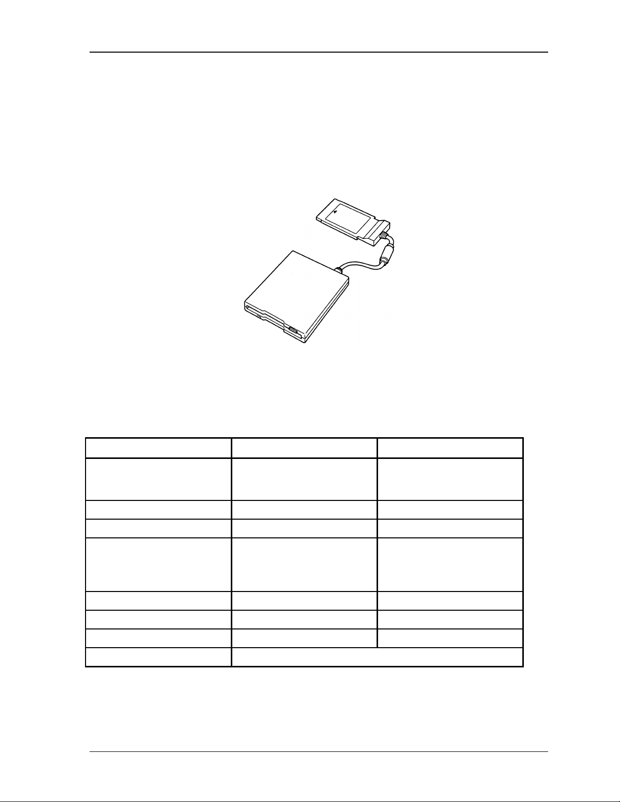
1.3 3.5-inch External FDD (Option)
The 3.5-inch external FDD is a thin, high performance reliable drive that supports 720KB
(formatted) 2DD and 1.44MB (formatted) 2HD disks. The FDD can be connected to the PC
card slot.
The FDD is shown in Figure 1-4.
Figure 1-4 3.5-inch FDD
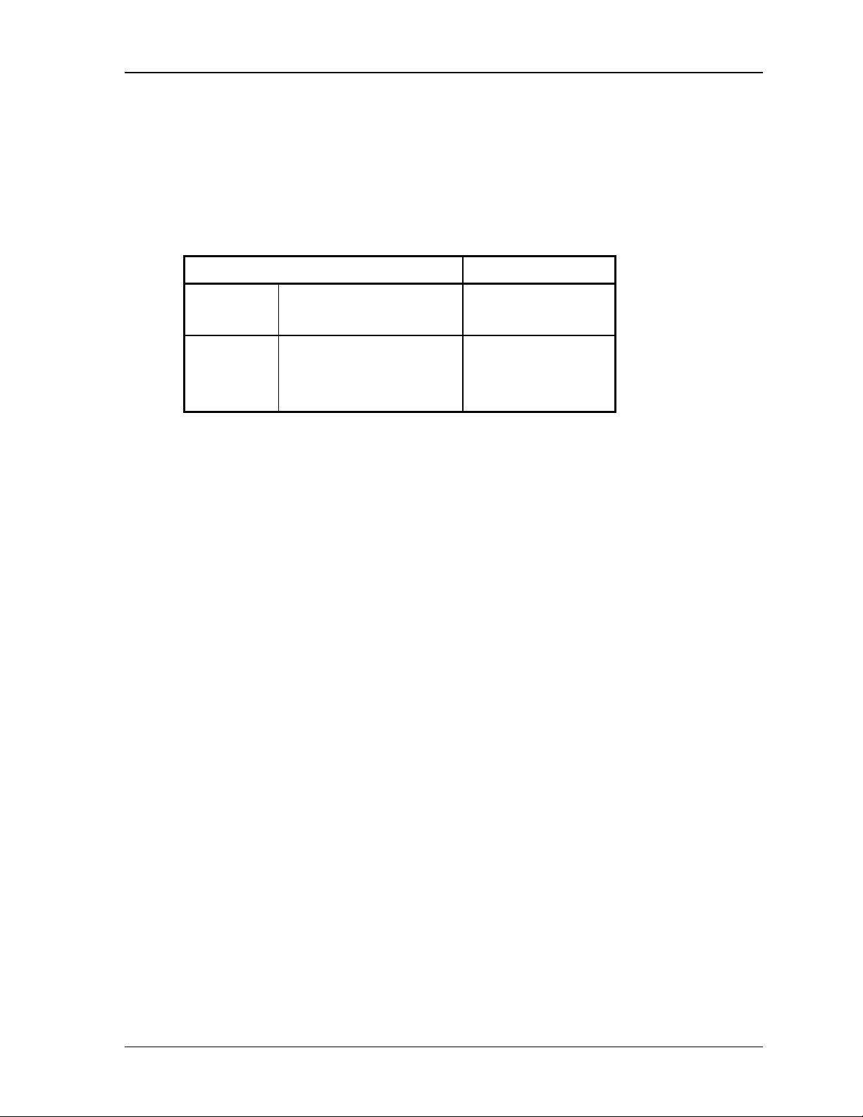
The specifications for the FDD are listed in Table 1-1.
Table 1-1 FDD specifications
Item 2MB mode 1MB mode
Storage capacity (KB)
Unformatted
Formatted
2,000
1,440
1,000
720
Number of heads 2 2
Number of cylinders 80 80
Access time (ms)
Track to track
Average
Head settling time
3
181
15
3
181
15
Recording track density (tpi) 135 135
Data transfer rate (Kbps) 500 250
Rotation speed (rpm) 300 300
Recording method Modified Frequency Modulation (MFM)

1 Hardware Overview 1.4 2.5-inch HDD
Libretto 50CT/70CT Maintenance Manual 1-9
1.4 2.5-inch HDD
The removable HDD is a random access non-volatile storage device. It has a non-removable
2.5-inch magnetic disk and mini-winchester type magnetic heads.
The Libretto 50CT computer supports a 815MB HDD.
∗The Libretto 70CT computer supports a 1.58GB HDD.
The HDD is shown in Figure 1-5.
Figure 1-5 2.5-inch HDD

1.4 2.5-inch HDD 1 Hardware Overview
1-10 Libretto 50CT/70CT Maintenance Manual
The specifications for the HDDs are listed in Table 1-2.
Table 1-2 HDD specifications
Libretto 50CT: 815MB HDD
Item Specifications
Formatted capacity (MB) 815
Number of disks 1
Logical heads 2
Bytes per sector 512
Rotation speed (rpm) 4,000
Recording method 8-9 RLL
*Libretto 70CT: 815MB HDD
Item Specifications
Formatted capacity (GB) 1.58
Number of disks 1
Logical heads 2
Bytes per sector 512
Rotation speed (rpm) 4,000
Recording method 8-9 RLL

1 Hardware Overview 1.5 Keyboard
Libretto 50CT/70CT Maintenance Manual 1-11
1.5 Keyboard
The 80- (USA) or 82- key (European) keyboard is mounted on the system unit. The
keyboard is connected to the keyboard controller on the system board through one 20-pin flat
cable. The AccuPoint, located on the right of the display panel, provides convenient control
of the cursor without requiring desk space for a mouse. The keyboard is shown in Figure
1-6.
See Appendix D for optional keyboard configurations.
Figure 1-6 Keyboard
The specifications for the keyboard are listed in Table 1-3.
Table 1-3 Keyboard specifications
Item Specifications
Input method Pantograph (Function keys use cylinders)
Pitch 15mm
Thickness 6mm

1.6 LCD Panel 1 Hardware Overview
1-12 Libretto 50CT/70CT Maintenance Manual
1.6 LCD Panel
The display panel contains a TFT color LCD module, a fluorescent lamp (FL), and an FL
inverter board.
1.6.1 LCD Module
The TFT color LCD enables display of up to 16M colors at a resolution of 640 x 480 pixels.
The LCD module is shown in Figure 1-7.
Figure 1-7 LCD module
The specifications for the LCD are listed in Table 1-4.
Table 1-4 LCD specifications
Item Specifications
Number of Pixels (pixels) 640x480
Dot pitch (mm) 0.192x0.192
Display area (mm) 122.8(H)x92.16(V)
Contrast 100:1
FL current (mA) 4.6/4.0/2.8/2.4*
(Bright/Semi-bright)
*NOTE: The FL currents at power on are:
Bright Semi-bright
Universal AC Adapter connected 4.6 mA 2.8 mA
Universal AC Adapter not connected 4.0 mA 2.4 mA
1 Hardware Overview 1.6 LCD Panel
Libretto 50CT/70CT Maintenance Manual 1-13
1.6.2 FL Inverter Board
The FL inverter board supplies high frequency current to light the LCD Fluorescent Lamp.
The specifications for the FL inverter are listed in Table 1-5.
Table 1-5 FL inverter board specifications
Item Specifications
Input Voltage (V) 5
Power (W) 2.2
Output Voltage (Vrms) 800
Current (mA) (4.6/4.0/2.8/2.4)*
(Bright/Semi-bright)
*NOTE: The FL currents at power on are:
Bright Semi-bright
Universal AC Adapter connected 4.6 mA 2.8 mA
Universal AC Adapter not connected 4.0 mA 2.4 mA

1.7 Power Supply 1 Hardware Overview
1-14 Libretto 50CT/70CT Maintenance Manual
1.7 Power Supply
The power supply provides two kinds of voltages to the system board, has one
microprocessor operating at 2 MHz, and performs the following functions:
1. Determines if the Universal AC Adapter or Main Battery Pack is connected to the
computer.
2. Detects DC output and circuit malfunctions.
3. Controls the LED icon and the speaker.
4. Detects a fully charged Main Battery Pack.
5. Controls power on/off.
6. Provides more accurate detection of a low Main Battery Pack.
7. Calculates the remaining Main Battery Pack capacity.
The power supply output rating is specified in Table 1-6.
Table 1-6 Power supply board output rating
DC Regulation
Use Name voltage (V) tolerance (%)
CPU, RAM, GA,
VGA, VRAM
B3V +3.3 ±5
GA, BIOS ROM,
KBC, PC card
VCC +12.0 ±5

1 Hardware Overview 1.8 Batteries
Libretto 50CT/70CT Maintenance Manual 1-15
1.8 Batteries
The computer has two types of batteries:
q Main battery pack
q RTC battery
Battery specifications are listed in Table 1-7.
Table 1-7 Battery specifications
Battery name Material Output voltage Capacity
Main battery pack Lithium-Ion 10.8 V 1,200 mAh
RTC battery Nickel Metal Hydride 2.4 V 11 mAh
1.8.1 Main Battery Pack
The removable main battery pack is the computer’s main power source when the Universal
AC Adapter is not connected. The main battery pack maintains the state of the computer
when the computer enters into hibernation mode.
1.8.2 Battery Icon
The icon color shows the status of the removable battery pack. Each color indicates:
Orange The battery is being charged. (Universal AC Adapter connected)
Green The battery is full charged. (Universal AC Adapter connected)
Blinking orange The battery is low when the power is on.
No light Under any other conditions, the LED does not light.
1.8.3 Battery Charging Control
A power supply microprocessor mounted on the system board controls whether the battery
charge is on or off and also detects a full charge when the Universal AC Adapter and battery
are connected to the computer. The system charges the battery using quick charge or trickle
charge.
q Quick Battery Charge
The battery quick charges when the Universal AC Adapter is connected and the
system is powered off or in stand-by mode.

1.8 Batteries 1 Hardware Overview
1-16 Libretto 50CT/70CT Maintenance Manual
Table 1-8 Time required for quick charge
Item Charging time
Power off or standby About 4.5 hours
If one of the following occurs, the Main Battery Pack quick charge process stops.
1. The Main Battery Pack becomes fully charged.
2. The Universal AC Adapter or Main Battery Pack is removed.
3. The Main Battery Pack or output voltage is abnormal.
q Trickle Battery Charge
The Main Battery Pack will trickle charge when the Universal AC Adapter is
connected and the system is on or when the main battery pack becomes fully charged.
The microprocessor automatically changes quick charge to trickle charge.
1.8.4 RTC battery
The RTC battery provides power to keep the current date, time, and other setup information
in memory while the computer is turned off. Table 1-9 shows the charging time and data
preservation period of the RTC battery.
Table 1-9 RTC battery charging/data preservation time
Item Time
Charging Time 48 hours
Data preservation period (full charge) About 1 month

Chapter 2
Troubleshooting Procedures
 Loading...