

Page 1
Single Phase Duplex
ELECTRICAL SHOCK HAZARD
Disconnect power before installing or servicing
this product. A qualified service person must install
and service this product according to applicable
electrical and plumbing codes.
EXPLOSION OR FIRE HAZARD
Do not use this product with flamable liquids
Do not install in hazardous locations as defined
by National Electrical Code, ANSI/NFPA 70.
Failure to follow these precautions could result in serious injury or death. Replace product immediately if switch cable becomes damaged
or severed. Keep these instructions with warranty after installation. This product must be installed in accordance with National Electric
Code, ANSI/NFPA 70 so as to prevent moisture from entering or accumulating within boxes, conduit bodies, fittings, float housing, or cable.
AE21L=3, AE21H=3, AE21L=4, AE21H=4
AE24L=3, AE24H=3, AE24L=4, and AE24H=4
Manufactured by SJE-Rhombus
Installation Instructions and Operation/Troubleshooting Manual
7000 Apple Tree Avenue
Bergen, New York 14416
Phone: 1-800-543-2550
Email: liberty@libertypumps.com
www.libertypumps.com
This control panel must be installed and serviced by a licensed electrician in accordance
with the National Electric Code NFPA-70, state and local electrical codes.
All conduit running from the sump or tank to the control panel must be sealed with conduit sealant
to prevent moisture or gases from entering the panel. NEMA 1 enclosures are for indoor use only,
primarily to provide a degree of protection against contact with enclosed equipment. Cable connectors
are not required to be liquid-tight in NEMA 1 enclosures. Do not use NEMA 1 enclosures if subjected
to rain, splashing water or hose-directed water. NEMA 4X enclosures are for indoor or outdoor
use, primarily to provide a degree of protection against corrosion, windblown dust and rain, splashing
water and hose-directed water. Cable connectors must be liquid-tight in NEMA 4X enclosures.
®
Warranty void if panel is modifi ed.
Call factory with servicing questions:
7249000B
1-800-543-2550
Page 2
Installation Instructions
Most single phase duplex panels are designed to operate as
three or four fl oat systems. The three fl oat system is standard
performing the common pump stop, lead pump start, and lag
pump start/high level alarm functions. The four fl oat system
utilizes separate fl oats for lag pump start and high level alarm.
NOTE: Options ordered may affect the number of fl oats and
their functions. Please reference the schematic provided
with the control panel for proper installation.
Installation of Floats
CAUTION: If control switch cables are not wired and mounted in
the correct location, the pump system will not function properly .
WARNING: Turn off all power before installing fl oats in pump
chamber. Failure to do so could result in serious or fatal
electrical shock.
1. Use fl oat label kit to identify and label cables on both
fl oat and stripped ends (stop, lead, lag, alarm, etc.). See
schematic for fl oat options.
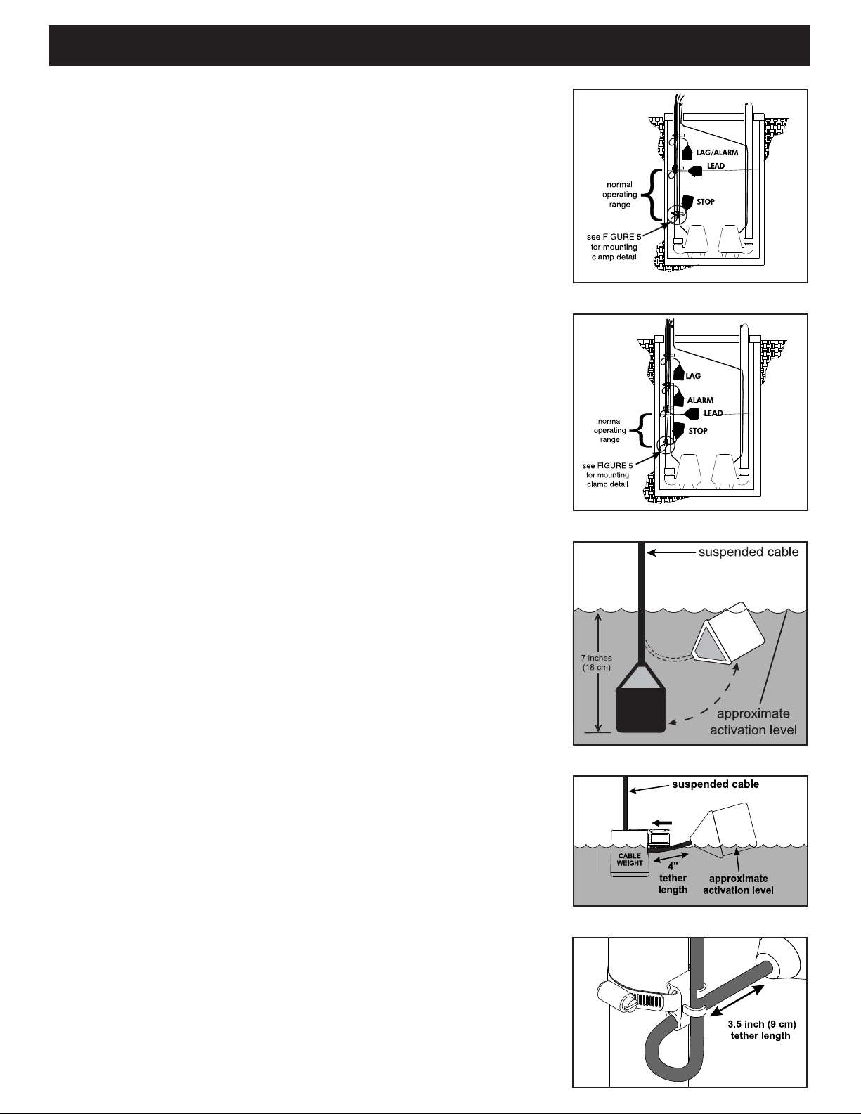
2. Determine your normal operating level, as illustrated in
Figures 1-2.
FIGURE 1: Three fl oat duplex
FIGURE 2: Four fl oat duplex
FIGURE 3: Internally weighted fl oat
3. Mount fl oat switches at appropriate levels as illustrated in
Figures 3-5. Be sure that fl oats have free range of motion
without touching each other, or other equipment in the basin.
If using the mounting clamp; follow steps 4-6.
4. Place the cord into the clamp as shown in Figure 5.
5. Locate the clamp at the desired activation level and secure
the clamp to the discharge pipe as shown in Figure 5.
NOTE: Do not install cord under hose clamp.
6. Tighten the hose clamp using a screwdriver . Over tightening
may result in damage to the plastic clamp. Make sure the
fl oat cable is not allowed to touch the excess hose clamp
band during operation.
NOTE: All hose clamp components are made of 18-8
stainless steel material. See your SJE-Rhombus® supplier
for replacements.
FIGURE 4: Float with cable weight
FIGURE 5: Mounting clamp detail
7249000B
- 2 -
Page 3

Installation Instructions
Mounting the control panel
1. Determine mounting location for panel. If
distance exceeds the length of either the fl oat
switch cables or the pump power cables,
splicing will be required. For outdoor or wet
installation, we recommend the use of a SJERhombus® liquid-tight junction box with liquidtight connectors to make required connections.
You must use conduit sealant to prevent
moisture or gases from entering the panel.
2. Mount control panel with mounting fl anges
furnished with control panel.
8. Run conduit to junction box. Drill proper size
holes for the type of conduit used. Attach liquidtight connectors to junction box.
9. Identify and label each wire before pulling
through conduit into control panel and junction
box. Pull pump power cables and control switch
cables through connectors into junction box.
Make wire splice connections at junction box.
10. Firmly tighten and seal all fi ttings on junction
box. Insure all cable connectors are liquid-tight
and sealed.
3. Determine conduit entrance locations on control
panel. Check local codes and schematic for
the number of power circuits required.
NOTE: Be sure the incoming power, voltage,
amperage, and phase meet the requirements
of the pump motors being installed. If in doubt,
see the pump identifi cation plate for electrical
requirements.
4. Drill proper size holes for type of connectors
being used.
NOTE: If using conduit, be sure that it is of
adequate size to pull the pump and switch
cables through. You must use conduit
sealant to prevent moisture or gases from
entering the panel.
5. Attach cable connectors and/or conduit
connectors to control panel.
11. If a junction box is not required, connect
pump and fl oat wires to proper position on
terminals. See schematic inside control panel
for terminal layouts.
12. Connect control/alarm and pump power
conductors to proper position on terminals.
See schematic inside control panel for terminal
connections.
NOTE: It is the recommendation of the factory to
use separate pump and control/alarm power
sources.
VERIFY CORRECT OPERATION OF CONTROL
P ANEL AFTER INST ALLATION
IS COMPLETE.
FOR INSTALLATION REQUIRING A SPLICE,
FOLLOW STEPS 6-10;
FOR INSTALLATION WITHOUT A SPLICE,
GO TO STEP 11.
6. Determine location for mounting junction box
according to local code requirements. Do not
mount the junction box inside the sump or
basin.
7. Mount junction box to proper support.
7249000B
- 3 -
Page 4

Operations
Single phase duplex panels are designed to operate with three or four fl oats for pump sequencing.
The standard fl oat functions are common pump
stop, lead pump start, lag pump start/alarm (three
fl oats), or separate lag and alarm fl oats (four
fl oats).
Three Float Operation: As the liquid level rises
to the stop fl oat and tips it to the ON (closed)
position, the panel will remain inactive. As the
liquid level tips the lead fl oat, the lead pump will
start. If the liquid level tips the lag/alarm fl oat, the
lag pump will start and the audio/visual alarm will
activate. Both pumps and the alarm will remain
active until the liquid level drops and the lag fl oat
is in the OFF (open) position. At this time the alarm
will silence. Both pumps will remain on until the
liquid level drops to normal and all three fl oats
are in the OFF (open) position. When both pumps
have stopped running, the alternator will switch
the lead pump and lag pump operating functions
in the next sequence.
Four Float Operation: The alarm will activate
and remain on only if the alarm fl oat is tipped to
the ON (closed) position.
Control and Alarm Lights
Lights will illuminate when control/alarm power is
supplied.
Float Status Lights
Lights will illuminate when the respective fl oat is
in the closed position.
Circuit Breaker (optional)
The pump circuit has a thermal-magnetic circuit
breaker which provides pump disconnect and
branch circuit protection.
Dry Auxiliary Contacts
(standard feature)
Normally open - Contacts are open under normal conditions and closed when alarm condition
is present.
Normally closed - Contacts are closed under
normal conditions and open when alarm condition
is present. Both types automatically reset once
alarm condition is cleared.
Alarm System (Horn and Indicator standard)
When an alarm condition occurs, a red light and
a horn will be activated. If the test/normal/silence
switch is moved to the silence position, the horn
will be silenced. When the alarm condition is
cleared, the alarm system is reset. The alarm
system can be tested by moving the test/normal/
silence switch to the test position.
HOA Switch
A hand-off-automatic switch is provided for each
pump. In the hand mode, the pump will turn on
unless other safety features are employed. In
the automatic mode, the pump will turn on from
commands by the fl oat switch(es).
Pump Run Lights
The run light will be ON in either the hand or the
automatic mode when the pump is called to run.
NOTE: Some options ordered may not be included
in this manual. Certain options will require alternative circuitry not including fl oat status and control/
alarm indicators.
For information regarding the operations
of options not listed here or servicing
questions, please call a Liberty Pumps
customer service technician at
1-800-543-2550
Warranty void if panel is modifi ed.
Control and Alarm Fusing
The control circuit and alarm circuit are fused
separately.
7249000B
- 4 -
Page 5

Troubleshooting
Control/Alarm Circuit Board Power
If the green power status indicators are not
illuminated:
1. Check to see if the fuses on the circuit board
are blown.
2. Check to see if the incoming control/alarm
power is present at TB1-1 and TB1-2.
the alarm light. If the light does not activate, replace
with bulb of same type.
Float Controls
Check the floats during their entire range of
operation. Clean, adjust, or replace damaged fl oats.
Checking the float resistance - The float
resistance can be measured to determine if the
fl oat is operating correctly or is defective. Use the
following procedure to measure the fl oat resistance.
Warning: Disconnect all incoming power to
panel. Failure to do so could result in serious
or fatal electrical shock.
1. Isolate the fl oat by disconnecting one or both of
the fl oat leads from the fl oat terminals.
If voltage is present and fuse is not blown,
please call factory for assistance.
Circuit Breaker (optional)
Check each pole of the circuit breaker for proper
resistance reading using the following procedure:
Warning: Disconnect all incoming power to
control panel. Failure to do so could result in
serious or fatal electrical shock.
1. Isolate the circuit breaker by disconnecting
either the line side or load side wires.
2. Place the ohmmeter leads across the
corresponding line and load terminals of each
pole.
3. With the ohmmeter on the R X 1 scale and the
breaker in the OFF position, the reading should
be infinity (very high resistance). With the
breaker in the ON position, the reading should
be nearly zero ohms (very low resistance). If
the readings are not as stated, replace the
circuit breaker with one of the same ratings.
2. Place one ohmmeter lead on one of the fl oat
wires, and the other ohmmeter lead on the other
fl oat wire.
3. Place the ohmmeter dial to read ohms and
place on the R X 1 scale. With the fl oat in the
“off” position, the scale should read infi nity (high
resistance). Replace the fl oat if you do not get
this reading. With the fl oat in the ON position,
the scale should read nearly zero (very low
resistance). Replace the fl oat if you do not get
this reading.
NOTE: Readings may vary depending on the
length of wire and accuracy of the measuring
device.
Fuses
Check the continuity of each fuse. With power
OFF, pull the fuses out of the fuse blocks. With the
ohmmeter on the R X 1 scale, measure resistance.
A reading of infi nity indicates a blown fuse and must
be replaced. Replace fuse with same type, voltage
and amp rating.
Alarm Horn
Moving the test/normal/silence switch to the test
position or activating the alarm fl oat should turn on
the alarm horn. If the horn does not sound, replace
horn with same type.
Alarm Light
Moving the test/normal/silence switch to the test
position or activating the alarm fl oat should turn on
7249000B
Magnetic Contactor Coil
Warning: Disconnect all incoming power to
panel. Failure to do so could result in serious
or fatal electrical shock. Check the coil by
disconnecting one of the coil leads. Measure the
coil resistance by setting the ohmmeter on the R
X 1 scale. A defective coil will read zero or infi nity,
indicating a short or opened coil respectively.
Replace defective contactor with same type.
- 5 -
Page 6

Liberty Pumps Three-Year Limited Warranty
*
NOTE: Liberty Pumps, Inc. assumes no responsibility for damage or injury due to disassembly in the
fi eld. Disassembly, other than at Liberty Pumps or its authorized service centers, automatically voids
warranty.
Liberty Pumps, Inc. warrants that pumps of its manufacture are free from all factory defects in material
and workmanship for a period of 3 years from the date of purchase. The date of purchase shall be
determined by a dated sales receipt noting the model and serial number of the pump. The dated sales
receipt must accompany the returned pump if the date of return is more than 3 years from the “CODE”
(date of manufacture) number noted on the pump nameplate.
The manufacturer’s obligation under this Warranty shall be limited to the repair or replacement of any
parts found by the manufacturer to be defective, provided the part or assembly is returned freight prepaid
to the manufacturer or its authorized service center, and provided that none of the following warrantyvoiding characteristics are evident.
The manufacturer shall not be liable under this Warranty if the product has not been properly installed;
if it has been disassembled, modifi ed, abused or tampered with; if the electrical cord has been cut,
damaged or spliced; if the pump discharge has been reduced in size; if the pump has been used in
water temperatures above the advertised rating, or water containing sand, lime, cement, gravel or other
abrasives; if the product has been used to pump chemicals or hydrocarbons; if a non-submersible motor
has been subjected to excessive moisture; or if the label bearing the serial, model and code number has
been removed. Liberty Pumps, Inc. shall not be liable for any loss, damage or expenses resulting from
installation or use of its products, or for consequential damages, including costs of removal, reinstallation
or transportation.
There is no other express warranty . All implied warranties, including those of merchantability and fi tness
for a particular purpose, are limited to three years from the date of purchase.
This Warranty contains the exclusive remedy of the purchaser, and, where permitted, liability for
consequential or incidental damages under any and all warranties are excluded.
7000 Apple Tree Avenue
Bergen, New York 14416
Phone: 1-800-543-2550
Email: liberty@libertypumps.com
©SJE-Rhombus
Printed in USA
PN1025047B • Rev 06/12
7249000B
www.libertypumps.com
- 6 -
Page 7

Three Phase Duplex
ELECTRICAL SHOCK HAZARD
Disconnect power before installing or servicing
this product. A qualified service person must install
and service this product according to applicable
electrical and plumbing codes.
EXPLOSION OR FIRE HAZARD
Do not use this product with flamable liquids
Do not install in hazardous locations as defined
by National Electrical Code, ANSI/NFPA 70.
Failure to follow these precautions could result in serious injury or death. Replace product immediately if switch cable becomes damaged
or severed. Keep these instructions with warranty after installation. This product must be installed in accordance with National Electric
Code, ANSI/NFPA 70 so as to prevent moisture from entering or accumulating within boxes, conduit bodies, fittings, float housing, or cable.
AE34=3-131, AE34=3-141, AE34=3-171, AE34=3-191,
AE34=3-511, AE34=4-131, AE34=4-141, AE34=4-171,
AE34=4-191, AE34=5-511, AE54=3-121, and AE54=4-121
Manufactured by SJE-Rhombus
®
Installation Instructions and Operation/Troubleshooting Manual
7000 Apple Tree Avenue
Bergen, New York 14416
Phone: 1-800-543-2550
Email: liberty@libertypumps.com
www.libertypumps.com
This control panel must be installed and serviced by a licensed electrician in accordance
with the National Electric Code NFPA-70, state and local electrical codes.
All conduit running from the sump or tank to the control panel must be sealed with conduit sealant
to prevent moisture or gases from entering the panel. NEMA 4X enclosures are for indoor or outdoor
use, primarily to provide a degree of protection against corrosion, windblown dust and rain, splashing
water and hose-directed water. Cable connectors must be liquid-tight in NEMA 4X enclosures.
Warranty void if panel is modifi ed.
Call factory with servicing questions:
7228000B
1-800-543-2550
Page 8

Installation Instructions
3.5 inch (9 cm)
tether length
7"
5
5
suspended cable
4"
tether
length
CABLE
WEIGHT
approximate
activation level
Most three phase duplex panels are designed to operate with three
or four fl oat systems. The three fl oat system is standard, perform-
ing the common pump stop, lead pump start, and lag pump start/
high level alarm functions. The four fl oat system utilizes separate
fl oats for each function.
NOTE: Options ordered may affect the number of fl oats and
their functions. Please reference the schematic provided with
the control panel for proper installation.
Installation of Floats
CAUTION: If control switch cables are not wired and mounted in
the correct order, the pump system will not function properly.
WARNING: Turn off all power before installing fl oats in pump cham-
ber. Failure to do so could result in serious or fatal electrical shock.
1. Use fl oat label kit to identify and label cables on both fl oat and
stripped ends (stop, lead, lag, alarm, etc.). See schematic for
fl oat options.
FIGURE 1: Three fl oat duplex
FIGURE 2: Four fl oat duplex
2. Determine your normal operating level, as illustrated in Figures
1 & 2.
3. Mount fl oat switches at appropriate levels as illustrated in Fig-
ures 3-5. Be sure that fl oats have free range of motion without
touching each other or other equipment in the basin.
If using the mounting clamp; follow steps 4-6.
4. Place the cord into the clamp as shown in Figure 5.
5. Locate the clamp at the desired activation level and secure the
clamp to the discharge pipe as shown in Figure 5.
NOTE: Do not install cord under hose clamp.
6. Tighten the hose clamp using a screwdriver. Over tightening
may result in damage to the plastic clamp. Make sure the fl oat
cable is not allowed to touch the excess hose clamp band
during operation.
FIGURE 3: Internally weighted fl oat
suspended cable
approximate
activation level
FIGURE 4: Float with cable weight
FIGURE 5: Mounting clamp detail
NOTE: All hose clamp components are made of 18-8
stainless steel material. See your SJE-Rhombus® supplier for
replacements.
- 2 -
7228000B
Page 9

Installation InstructionsInstallation InstructionsInstallation InstructionsInstallation InstructionsInstallation InstructionsInstallation InstructionsInstallation InstructionsInstallation InstructionsInstallation Instructions
Mounting the Control Panel
1. Determine mounting location for panel. If dis-
tance exceeds the length of either the fl oat
switch cables or the pump power cables,
splicing will be required. For outdoor or wet
installation, we recommend the use of an SJE-
®
Rhombus
tight connectors to make required connections.
You must use conduit sealant to prevent
moisture or gases from entering the panel.
2. Mount control panel with mounting devices
furnished.
3. Determine conduit entrance locations on control
panel.
NOTE: Be sure the incoming power, voltage,
amperage, and phase meet the requirements
of the pump motors being installed. If in doubt,
see the pump identifi cation plate for electrical
requirements.
4. Drill proper size holes for type of connectors
being used.
NOTE: If using conduit, be sure that it is of ad-
equate size to pull the pump and switch cables
through.
5. Attach cable connectors and/or conduit con-
nectors to control panel.
liquid-tight junction box with liquid-
8. Identify and label each wire before pulling
through conduit into control panel and junction
box. Make wire splice connections at junction
box.
9. Firmly tighten all fi ttings on junction box.
10. If a junction box is not required, pull cables
through conduit into control panel.
11. Set motor protective switches:
a) set the dials to match motor full load
amps.
b) turn dial on motor protective switch to the
ON position.
NOTE: Resetting the dial with power applied
to the motor protective switch could start
the motor.
12. Connect pump wires directly to the motor con-
tactors terminal positions T1, T2, and T3.
NOTE: Three-phase motors will run in either
direction. Check pump motor before installation
for proper rotation. To correct rotation, change
pump cable connections on any two terminals
T1-T2-T3.
13. Connect “power-in” conductors to proper
locations: 208/240/480 VAC on the 3 position
terminal block. Install tagged factory wire to
appropriate transformer primary voltage tap.
FOR INSTALLATION WITHOUT A SPLICE,
GO TO STEP 10; FOR INSTALLATION RE-
QUIRING
A SPLICE, FOLLOW STEPS 6-9.
6. Determine location for mounting junction box
according to state and local code requirements.
Mount the junction box to proper support.
7. Run conduit to junction box. Drill proper size
holes for the type of conduit used. Attach connectors to junction box.
7228000B
VERIFY CORRECT OPERATION
OF CONTROL PANEL AFTER
INSTALLATION IS COMPLETE.
- 3 -
Page 10

Operations
Three phase duplex panels are designed to operate
with three or four fl oats for pump sequencing. The
standard fl oat functions are common pump stop,
lead pump start, lag pump start/alarm (three fl oats),
or separate lag and alarm fl oats (four fl oats). Other
fl oat options, such as redundant off, are available.
Three Float Operation: As the liquid level passes
the stop fl oat and tips it to the ON (closed) position,
the panel will remain inactive. As the liquid level
tips the lead fl oat, the lead pump will start. If the
liquid level tips the lag/alarm fl oat, the lag pump
will start and the audio/visual alarm will activate.
Both pumps and the alarm will remain active until
the liquid level drops and the lag fl oat is in the
OFF (open) position. At this time the alarm will
silence. Both pumps will remain on until the liquid
level drops to normal and all three fl oats are in
the OFF (open) position. When both pumps have
stopped running, the alternator will switch the lead
pump and lag pump operating functions in the next
sequence.
Four Float Operation: The alarm will activate and
remain on only if the alarm fl oat is tipped to the ON
(closed) position.
Alarm System (Horn and Indicator)
When an alarm condition occurs, a red light and
a horn will be activated. If the test/normal/silence
switch is moved to the silence position, the horn will
be silenced. When the alarm condition is cleared,
the alarm system is reset. The alarm system can
be tested by moving the test/normal/silence switch
to the test position.
Control/Alarm Switch
Allows the control/alarm power to be turned on
or off.
HOA Switch
A hand-off-automatic switch is provided for each
pump. In the hand mode, the pump will turn on
unless other safety features are employed. In
the automatic mode, the pump will turn on from
commands by the fl oat switches.
wired in series with the magnetic contactor coil so
that on an overload trip, the magnetic contactor
will be disabled. In the event of an overload trip,
the motor protective switch must be reset by fi rst
turning the selector handle counterclockwise to
the OFF position and then turning the handle 90
clockwise to the ON position.
o
Control/Alarm Light
The light will illuminate when the control ON/OFF
switch is in the ON position.
Pump Run Lights
Each pump has a run light. The run light will be ON
in either the hand or the automatic mode when the
pump is called to run.
Float Status Lights
Lights will illuminate when the respective fl oat is in
the closed position.
Dry Auxiliary Contacts (optional)
Normally open - Contacts are open under normal
conditions and closed when alarm condition is
present.
Normally closed - Contacts are closed under
normal conditions and open when alarm condition
is present.
Both types automatically reset once alarm condition
is cleared.
Seal Failure Circuit and Indicator Light
(optional)
The seal fail circuit has resistance sensitivity and
will sense the presence of water in the pump seal
chamber. Upon installation, turn the sensitivity
dial on the seal fail module to the point where the
light turns on, then dial back slowly until the light
turns off. If water enters the seal chamber at this
point, the seal fail circuit will sense the change in
resistance. After a short time delay, the indicator
light will turn on. When the condition is cleared, the
relay will de-energize and the indicator light will turn
off. The seal fail relay has a sensitivity adjustment
so that false readings may be tuned out.
Motor Protective Switch
A motor protective switch is supplied for each
pump to provide an adjustable overload, branch
circuit protection and disconnect. The overload
must be set in the fi eld. To set the overload, dial
the amp scale to the pump’s full load amp rating
(FLA). If the FLA’s are unknown, use a calibrated
amp meter to measure the pump amperage draw
under loaded conditions. An auxiliary contact is
7228000B
Thermal Cutout (optional)
The thermal cutout is wired in series with the
magnetic contactor coil. If the pump’s thermal
switch opens on high temperature, the contactor
will turn off and stop the pump. When the thermal
switch cools and closes, the magnetic contactor
will turn on if the pump is called to run.
NOTE: Some options ordered may not be included
in this manual.
- 4 -
Page 11

Troubleshooting
Alarm Horn
Pressing the alarm test/normal/silence switch to
the test position or activating the alarm fl oat should
turn on the alarm horn. If the horn does not sound,
replace with horn of same type.
Alarm Light
Pressing the alarm test/normal/silence switch to
the test position or activating the alarm fl oat should
turn on the alarm light. If the light does not activate,
replace with bulb of same type.
3. Place the ohmmeter dial to read ohms and
place on the R X 1 scale. With the fl oat in the
“off” position, the scale should read infi nity
(high resistance). Replace the fl oat if you do
not get this reading. With the fl oat in the ON
position, the scale should read nearly zero
(very low resistance). Replace the fl oat if you
do not get this reading.
NOTE: Readings may vary depending on the
length of wire and accuracy of the measuring
device.
Fuses
Check the continuity of the fuse. Pull the fuse out
of the fuse block. With the ohmmeter on the R X
1 scale, measure resistance. A reading of infi nity
indicates a blown fuse and must be replaced.
Replace fuse with same type, voltage and amp
rating.
Alternating Relay or Device
The alternation can be sequenced by lifting the
fl oat switches or making jumper wires to simulate
the fl oats closing. If the alternator fails during
testing, replace with same type. Consult factory
at 1-800-RHOMBUS (1-800-746-6287) when in
doubt about testing procedures or results.
Float Controls
Check the fl oats through their entire range of
operation. Clean, adjust, or replace damaged
fl oats.
Checking the float resistance - The float
resistance can be measured to determine if the
fl oat is operating correctly or is defective. Use
the following procedure to measure the float
resistance:
1. Isolate the fl oat by disconnecting one or both
of the fl oat leads from the fl oat terminals.
Magnetic Contactor
Contacts - Check the contacts for severely burnt
or welded contacts. The contactor arm should
move freely.
Coil - Measure the coil by disconnecting one of the
coil leads. Measure the coil resistance by setting
the ohmmeter on the R X 1 scale. A defective
coil will read zero or infi nity, indicating a short or
opened coil respectively . If contactor is defective,
replace with same type.
NOTE: Readings may vary slightly depending on
the and accuracy of the measuring device.
Motor Protective Switch
T est by inserting a paper clip or other small device
into the test hole and push to the left. The relay
should trip.
2. Place one ohmmeter lead on one of the fl oat
wires, and the other ohmmeter lead on the
other fl oat wire.
7228000B
- 5 -
Page 12

Liberty Pumps Three-Year Limited Warranty
*
NOTE: Liberty Pumps, Inc. assumes no responsibility for damage or injury due to disassembly in the
fi eld. Disassembly, other than at Liberty Pumps or its authorized service centers, automatically voids
warranty.
Liberty Pumps, Inc. warrants that pumps of its manufacture are free from all factory defects in material
and workmanship for a period of 3 years from the date of purchase. The date of purchase shall be
determined by a dated sales receipt noting the model and serial number of the pump. The dated sales
receipt must accompany the returned pump if the date of return is more than 3 years from the “CODE”
(date of manufacture) number noted on the pump nameplate.
The manufacturer’s obligation under this Warranty shall be limited to the repair or replacement of any
parts found by the manufacturer to be defective, provided the part or assembly is returned freight prepaid
to the manufacturer or its authorized service center, and provided that none of the following warrantyvoiding characteristics are evident.
The manufacturer shall not be liable under this Warranty if the product has not been properly installed;
if it has been disassembled, modifi ed, abused or tampered with; if the electrical cord has been cut,
damaged or spliced; if the pump discharge has been reduced in size; if the pump has been used in
water temperatures above the advertised rating, or water containing sand, lime, cement, gravel or other
abrasives; if the product has been used to pump chemicals or hydrocarbons; if a non-submersible motor
has been subjected to excessive moisture; or if the label bearing the serial, model and code number has
been removed. Liberty Pumps, Inc. shall not be liable for any loss, damage or expenses resulting from
installation or use of its products, or for consequential damages, including costs of removal, reinstallation
or transportation.
There is no other express warranty . All implied warranties, including those of merchantability and fi tness
for a particular purpose, are limited to three years from the date of purchase.
This Warranty contains the exclusive remedy of the purchaser, and, where permitted, liability for
consequential or incidental damages under any and all warranties are excluded.
7000 Apple Tree Avenue
Bergen, New York 14416
Phone: 1-800-543-2550
Email: liberty@libertypumps.com
©SJE-Rhombus
Printed in USA
PN1025048B • Rev 06/12
7228000B
www.libertypumps.com
- 6 -
 Loading...