

Page 1
Installation Manual 4414000B
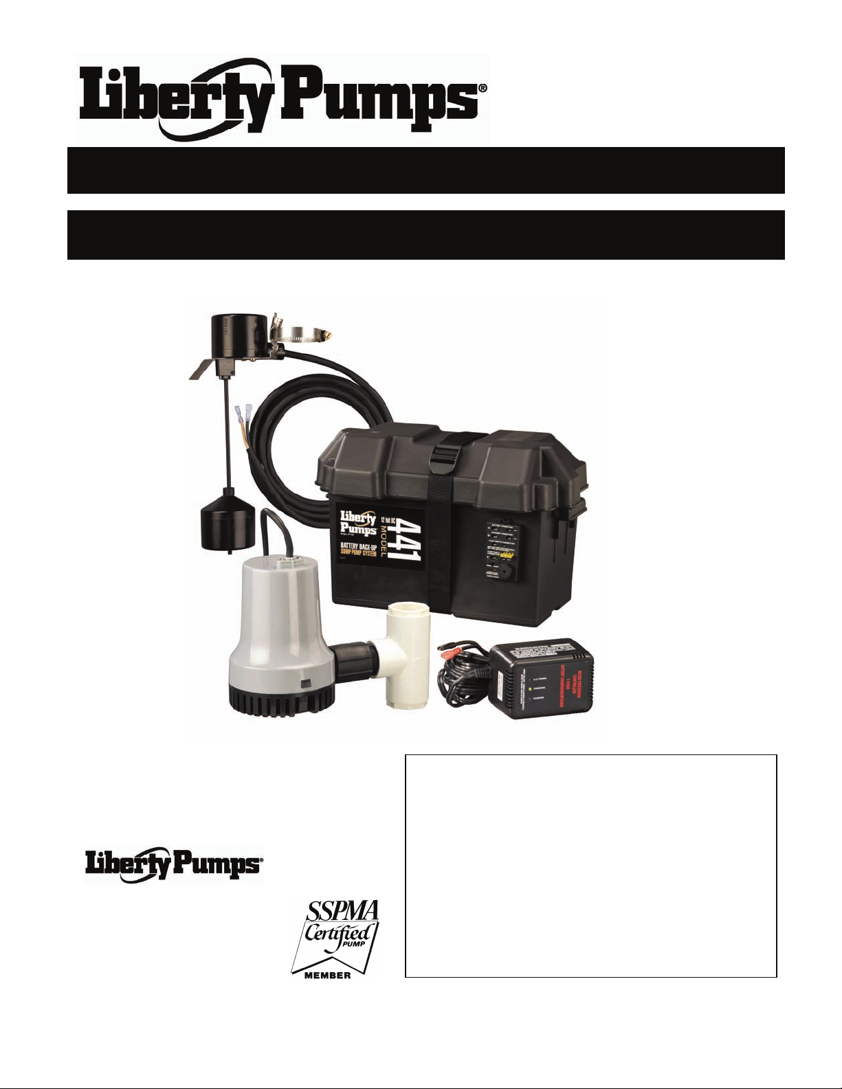
Model 441 Battery Backup System
*Do not throw away or lose this manual.
IMPORTANT:
Prior to installation, record Model, Serial Number, and
Code Number from pump nameplate for future reference.
MODEL ________________________
SERIAL ______________________
7000 Apple Tree Avenue
Bergen, NY 14416
Phone: (800) 543-2550
Fax: (585) 494-1839
www.libertypumps.com
©Copyright 2009 Liberty Pumps Inc. All rights reserved 1
CODE ______________________
INSTALLATION
DATE _______________________
Page 2

1. General Information – All Models
The battery back-up sump pump system is not a substitute for your primary sump pump. It is designed to temporarily
back up your primary sump pump during a power outage or other problem which prevents normal operation of the
primary pump. Do not use this system to pump flammable liquids or chemicals. Pump clear water only with this pump.
Keep battery charger dry and protected from damage.
In an emergency (such as an extended power outage) which depletes the system deep cycle battery, your automobile
battery may be temporarily substituted. Be sure to replace the system deep cycle battery as soon as possible. Use of
an automobile battery instead of a deep cycle battery in this system will significantly reduce system total performance.
Automobile batteries are not designed for this type of application and will be quickly ruined by the repeated
charge/discharge cycling. Do not use GEL-type batteries or maintenance-free batteries with this charger. GEL-type
batteries require a lower voltage than the charger is designed for; they may overcharge. Maintenance-free (sealed)
batteries require a higher voltage and may never reach full charge.
• Hazardous Voltage. Can cause severe or fatal electrical shock. Do not plug in or unplug the battery charger while
standing on a wet floor or in water. Be sure one hand is free when plugging in or unplugging the charger. If
basement floor is wet, disconnect power to basement before walking on floor.
• DO NOT bypass grounding wires or remove ground prong from at tachment plugs.
• Risk of electric shock. Always disconnect the pump from the power source before handling or making
adjustments.
• Battery acid is corrosive. Do not spill on skin, clothing, or battery charger. Wear eye and head protection when
working with the battery. Connect and disconnect DC output terminals only after removing the charger from the AC
outlet. Never allow the DC terminals to touch each other.
• To avoid danger of fire or explosion, keep sparks and flame (pilot light) away from battery.
• The electrical connections and wiring for a pump installation should only be made by qualified personnel.
• This pump is supplied with a grounding conductor and grounding-type attachment plug. To reduce the risk of
electric shock, be certain that it is connected only to a properly grounded, grounding-type 15 Amp receptacle. A
ground fault circuit interrupter (GFCI) is recommended for use on any electrical appliance submerged in wate r.
• DO NOT use an extension cord.
• The electrical outlet shall be within the length limitations of the pump power cord, and at least 4 feet above floor
level to minimize possible hazards from flood conditions.
• The installation must be in accordance with the National Electric Code, Uniform Plumbing Code, International
Plumbing Code, as well as all applicable local codes and ordinances.
• Sump and sewage pumps often handle materials which could cause illness or disea se. We ar adequate protective
clothing when working on a used pump or piping.
• Keep clear of suction and discharge openings. To prevent injury, never insert fingers into pump while it is plugged
in.
• DO NOT use this product for flammable or corrosive liquid.
• DO NOT use this product in applications where human contact with the pumped fluid is common (such as
swimming pools, fountains, etc.)
• NEVER dispose of materials such as paint thinner or other chemicals down drains, as they can chemically attack
and damage pump components, potentially causing product malfunction or failure.
• Use this system only for backup sump pump duty in a residential application. It is not designed as a primary sump
pump.
• Risk of flooding. DO NOT run pump dry. To do so will damage seals and can cause leaking and property damage.
• DO NOT use pumps in water over 140°F (60°C).
• DO NOT use pumps in mud, sand, cement, oil or chemicals.
©Copyright 2009 Liberty Pumps Inc. All rights reserved 2
Page 3

• DO NOT modify the pump in any way.
• DO NOT lift or carry pump by power cord.
• DO NOT remove any tags from pump or cords.
• If pump is installed during construction before power is available, it must be protected from the environment to
prevent water from entering through the cord plug end, etc.
• Keep battery charger and battery box off of the floor and in a dry, cool, well ventilated area.
• Make sure sump is clear of debris. Debris can damage the pump which can result in flooding
• Maximum vertical pumping distance is 24 feet (7.3M)
• The pump should be
operation. The float must be free to move freely through its complete travel without any restrictions. Periodically
(at least every three months), the pump should be tested to ensure proper function. This may be done by
disconnecting power to the primary pump so that the water level rises to activate the back-up unit. Be sure to
follow all safety precautions and remember to reconnect power to the primary pump and verify proper operation
after conclusion of the test.
NOTICE: If a Carbon Monoxide (CO) sensor is installed, it must be at least 15 feet away from battery charger in order
to avoid nuisance CO alarms. Please refer to your CO detector’s installation guidelines for more information.
checked frequently for debris and/or build-up which may interfere with pump of float switch
2. Installation of Pump
BATTERY BACKUP SYSTEM
INSTALLATION AND OPERATION
NOTICE:
• Install this system during a time when the primary pump will not be needed. Gather all supplies before starting.
Read all warnings and installation steps before you start.
• Be prepared for water to leak from the coupling or piping when disassembling or cutting the discharge pipe.
Protect system components, tools and supplies from getting wet. Dry any work areas that get wet immediately.
BASIC TOOLS AND
MATERIALS NEEDED
• Channel locks or large
pliers
• Tape measure
• Socket wrench or 5/16”
Nut driver
• Side cutters
• Hacksaw (to cut PVC
pipe)
• Medium size pliers
• Pencil
• Teflon tape
• PVC glue (solvent weld)
• PVC pipe cleaner
• Cloth towel
• Size 24M or 27M Marine
Deep Cycle Battery
Maximum battery capacity is
100 ampere-hours.
Personal injury and flood hazard. Do not turn the pump on until all the fittings are glued and the glue has dried.
Loose fittings can unexpectedly disconnect from pipes and cause personal injury and flooding.
©Copyright 2009 Liberty Pumps Inc. All rights reserved 3
Page 4
PREPARATION FOR INSTALLATION
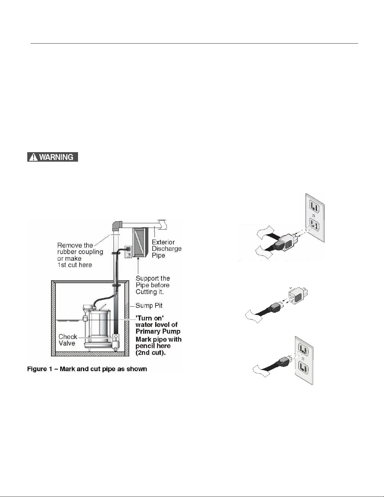
1. Locate the “on” water level of the primary sump pump. Mark this location on the discharge pipe with a pencil.
See Figure 1.
2. Drain the sump pit. The water level must be pumped down as low as possible before going on to the next step.
To drain the sump pit follow either step “2A” or “2B” (below).
2A. Raise the float on the float switch until the pump turns on. Use a wooden broom handle or a stick to do
this.
2B. If the sump pump has a piggy-back type power cord, remove the float switch power cord plug from the
outlet and plug the pump power cord plug directly into the outlet. See Figure 2.
3. Confirm sump has been drained and shut-off pump. NOTICE: Do not let the pump run dry. This will damage
the pump.
4. Unplug the pump
Electrical shock hazard. Shock can burn or kill. Do not use metal or any other electrical
conducting material to raise the float. Do not make contact with the water in the sump pit. Failure
to follow this warning can result in personal injury or death.
1. Unplug the “Piggy-back” float switch cord
plug and the pump power cord plug from
grounded electrical outlet
2. Separate the float switch cord plug
from the sump pump cord plug.
3. Plug the pump
power cord plug
directly into the outlet
Figure 2 - To bypass the float
©Copyright 2009 Liberty Pumps Inc. All rights reserved 4
Page 5

INSTALLATION
5. To separate the primary pump from the discharge
pipe:
5A. For applications with rubber couplings: remove
the coupling clamp with a nut driver.
5B. For applications without rubber couplings: cut
the PVC discharge pipe with a hacksaw above the
basement floor, at a comfortable level. You will
need a new rubber coupling for reassembly. See
Figure 1 on Page 4. NOTICE:
will be filled with water. Drain the water from the
discharge pipe assembly. Keep the work area dry.
Risk of pinching hands or fingers. To
avoid a hand injury from a collapse of plumbing,
support the pipe above the separation before cutting or
disassembly. See Figure 1.
6. Lift the primary pump and discharge pipe assembly
out of the sump.
Risk of electrical shock. Do not lift the
pump by the electrical cord; lift pump only by the lifting
ring, discharge pipe, or handle on the pump. Lifting by
the cord can damage the cord.
The discharge pipe
INSTALL BACKUP PUMP
There are two ways to install the Battery Back-up Pump.
Method A and Method B. See Figure 3 to determine which
method to use. Both methods are acceptable.
©Copyright 2009 Liberty Pumps Inc. All rights reserved 5
Page 6

INSTALLATION cont.
Method A
The recommended method suggests installing both of the pumps on the floor of the sump pit. See Figure 4. The
minimum required sump basin diameter, at the bottom of the pit and the recommended depth of the sump basin is 18”.
Some additional materials you will need are a rubber coupling with clamps to fit your discharge pipe diamete r, (2) 1 1/4” 90° elbows, and (2) 1-1/4” close pipe nipples.
1. Make the second cut in the discharge pipe at the pencil mark as shown in Figure 1 on page 4, and in Figu re 4,
on Page 5. Clean the pipe ends with a cloth towel and set the cut-off piece of discharge pipe aside.
2. If already assembled, remove the check valve assembly (Key No. 3 on page 12) from the battery back-up pump
discharge and set it aside. See Figure 5. The check valve assembly will be used later, during assembly.
3. Apply (2) wraps of Teflon tape to the discharge threads of the pump and thread a 90° elbow (purchased locally)
onto the discharge of the back-up pump.
4. Wrap the threads of all 3 of the close pipe nipples (Key No. 2) with 2 turns of Teflon™ tape and thread one of
them into the elbow. Set the other 2 aside.
5. Thread the check valve assembly, removed back in step 2, onto the close pipe nipple.
NOTICE: Make sure the check valve is installed in the correct direction. See the inset drawing in Figure 5.
6. Thread a close pipe nipple into the other end of the check valve.
7. Thread the second 90° elbow onto the pipe nipple.
8. Thread the last pipe nipple into the elbow.
9. Thread the tee onto the pipe nipple and set this assembly aside.
10. Install a short length of pipe into the top of the check valve in the primary pump discharge. See Figure 4.
NOTICE: There must be a check valve installed in the Primary Sump Pump discharge pipe between the tee
and the Primary Sump Pump. This will prevent recirculation into the Primary Pump when the Backup Sump
Pump comes on.
11. If your discharge pipe is 1-1/2”, you will not need the
reducer bushings. If your discharge pipe diameter is
1-1/4”, you will need to glue the reducer bushings into
the tee.
12. Slip the tee and the back-up pump subassembly onto
the short pipe exiting the primary pump.
13. Glue the cut off piece of pipe into the top of the tee
(with reducer bushing if 1-1/4” pipe).
14. Mount the preassembled vertical switch to the
discharge pipe above the tee with the provided clamp.
Adjustments may be needed later and can be
achieved by loosening the clamp and sliding the
switch bracket up or down on the discharge pipe to
attain the desired activation level.
15. Skip to the section “Cut the Discharge Pipe”, Page 8.
Method B
Method B suggests installing the back-up pump above the
primary sump pump. See Figure 6. The minimum required
sump basin diameter for this type of installation is 13.5” at
the bottom of the pit, and the minimum recommended depth
of the basin is 22”.
©Copyright 2009 Liberty Pumps Inc. All rights reserved 6
Figure 6 –Method B installation diagram
Page 7

INSTALLATION cont.
1. Make a second cut in the discharge pipe at the pencil mark made in step 1, on Page 4, and set the cut-off piece
of discharge pipe aside. See Figures 1 and 6.
2. Wrap the threads of the close nipple (Key No. 2 on Page 12) and backup pump (Key No.4) counterclockwise
with 2 turns of Teflon
3. Thread the check valve onto the backup pump discharge ensuring that the valve housing and inner valve fla p
are oriented correctly. See Figure 5.
4. Thread the close pipe nipple into the check valve.
5. To thread the tee (Key No. 1) onto the close nipple. If needed, hold the check valve with the channel locks,
insert the screwdriver into the tee for leverage, and tighten the tee with the screwdriver. Finish with the tee in a
straight up and down (vertical) position.
6. Clean the pipe ends with the cloth towel.
7. Glue the cut-off piece of discharge pipe into the top of the tee.
NOTICE: There must be a check valve installed in the primary sump pump discharge pipe between the tee and the
primary sump pump. This will prevent recirculation into the primary pump when the backup sump pump comes on.
NOTICE: If your pipe is 1-1/4”, you will need to glue the reducer bushings (Key No. 12) into the tee and glue the pipe
into the bushing. Place the assembly onto the primary discharge pipe. Do not glue the tee onto the primary pump
discharge pipe at this time as it will need to be removed later.
8. Mount the back-up pump float switch assembly (Key No. 6) loosely to the discharge pipe per steps shown on
pages 6 and 7. Approximately 2.5” (63.5 mm) of cord length should be left between the float and the clamp. Do
not tighten the clamp at this time as adjustments may be needed later.
TM
tape.
Cut the Discharge Pipe:
1. Put the double pump assembly
into the sump pit.
NOTICE: The discharge pipe now
overlaps the discharge pipe that
leads outside.
2. Mark the discharge pipe where it
should be cut. Be sure to leave
a 1/4” air gap between the ends
of the pipes. This gap will absorb
the noise from vibration and
allow for flexibility.
3. Make the third cut. See Figure 7.
TRIAL ASSEMBLY OF
DOUBLE PUMP
ASSEMBLY IN THE
SUMP PIT:
1. Connect the pump discharge
pipe to the exterior discharge
pipe with a rubber coupling and
clamps. Do not tighten the
clamps until all the final
adjustments are complete.
2. Make the final adjustments. Make sure the pumps and the switches do not interfere with each other. Make sure
there is plenty of room for the float switches to either swing or to move up and down from their “off” to their “on”
positions.
©Copyright 2009 Liberty Pumps Inc. All rights reserved 7
Note: Always install the back-up sump pump as close to the bottom
of the sump pit as possible.
Figure 7 – Make the third cut to remove the excess discharge pipe.
Page 8
INSTALLATION cont.
Mark and Glue Assembly:
1. Mark the pipe and the fittings at all the connections with a pencil. These marks will be used as a reassembly
guide while gluing to be sure everything is still in the right place and nothing has moved.
2. Loosen the rubber coupling and clamp connection.
3. Carefully pull the double pump assembly back out of the pit.
4. Take the tee assembly off of the primary discharge pipe. Do Not unscrew any of the Teflon taped fittings.
5. Clean all the PVC pipe ends with the PVC cleaner.
Hazardous fumes. Follow the cement and cleaner manufacturer’s inst ructions. Use the PVC
cement in a well ventilated area away from fire or flames.
6. Glue the PVC fittings where indicated by the pencil marks. Wait 10 minutes for the glue to cure.
Final Assembly:
1. Put the double pump assembly back into the pit.
2. Install and tighten the rubber coupling and clamp kit.
3. Make the final float switch adjustments and tighten the mounting clamp and cabl e ties.
ELECTRICAL CONNECTIONS
Hazardous voltage can cause serious or fatal electrical shock. Review safety instructions before
operating charger. Do not modify cord or plug.
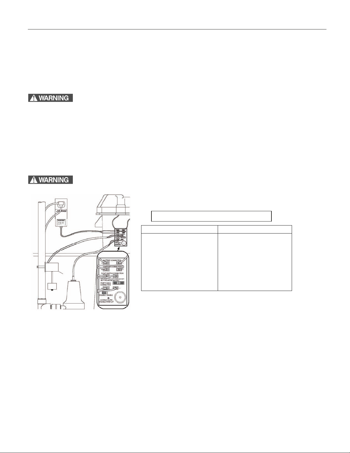
Table I – Model 441 Wiring Connections
Connect the To the Junction Box’s
Positive (+) lead from the battery
Negative (–) lead from the battery
Positive lead from the charger
Negative lead from the charger
Backup pump float switch
Positive lead from the pump
Negative lead from the pump
(2 wires)
Positive battery connection
Negative battery connection
Positive charger connection
Negative charger connection
Float switch connection
Positive pump connection
Negative pump connection
(2 wires)
Figure 8 – Wiring Connections for Model 441
CHARGER/BATTERY INSTALLATION
NOTICE: An alarm, located in the junction box, automatically sounds when the system runs if the alarm is in the
“Enable” position. The alarm is silenced when the alarm switch is in the “Disable” position.
Apply the square two-sided tape (provided, Key No. 9) to the back of the junction box. Press the junction box onto the
1.
battery box as illustrated in Figure 8.
2. Connect the charger as shown in Table I and in Figure 9.
3. Plug the charger into a 115-120 Volt AC outlet delivering at least 15 amps. Do not use a switch controlled o u tlet. Mark
circuit in main power panel “Backup sump pump power supply; do not turn off”.
4. With the charger properly connected and plugged in, the panel on the front of the charger will show one of the conditions
illustrated in Figure 9.
©Copyright 2009 Liberty Pumps Inc. All rights reserved 8
Page 9

INSTALLATION cont.
Red LED - power is present
Yellow LED - Prequalification test stage is complete and testing or charging in process
Green/Occasional Yellow - Charger turns on intermittently to maintain proper charge
Green LED -Charging complete
Green/Yellow LEDs Alternately Flashing - System is in Error Mode (see Table II, Page 10)
NOTICE: For more detailed information, see “Charger Operation” on page 10.
Figure 9 – Model 441 Charger LED Panel
TABLE II - Model 441 Charger Error Table (Green and Yellow LEDs will flash alternately)
Error Description Possible Causes Fix
The Battery Failed Pre-
Qualification Test
Battery Over-Voltage The Charger is connected to a 24 Volt
Charge Time Monitor Battery took too long to complete its charge:
Excessive Battery Drain Pump motor ran during charging (that is,
Reverse Battery
Connection
The battery is highly sulfated
The charger is connected to a six-volt
battery
Battery
A. Load applied (e.g. the pump motor
started) during charging
B. The battery ampere-hour rating is too
large (Max. 96 ampere-hours)
with the main A.C. power ON), causing the
system to shut down
Charger is connected backwards to the
battery. (That is, Charger (+) to Battery (-)
and vice versa)
Replace the battery with a 12-Volt deep-cycle
marine battery
Replace the battery with a 12-Volt deep-cycle
marine battery
Replace the battery with a 12-Volt deep-cycle
marine battery
Be sure pump cannot start during charging; reset
the charger
Replace with correct size battery (see Page 4)
Check primary sump pump. The BBU generally
runs only when the main A.C. power is out. If there
has not been any power outage and the BBU has
run, the primary pump itself may have failed
Reconnect Charger (+) to Battery (+)/(-) to (-)
Battery Overheated Cells in an old battery may deteriorate with
age
Replace battery with a 12-Volt deep-cycle marine
battery
TABLE III - Model 441 Charger Light Indications
Charger Light On/Off/Flashing Indicates
All Lights Off System is not receiving AC power
Power (Red Light) On
Off
Charging (Yellow Light) Flashing 1x/Second
On, steady
Flashing alternately with
green light
Charged (Green Light) On, yellow light Off
Flashing alternately with
yellow light
©Copyright 2009 Liberty Pumps Inc. All rights reserved 9
System is receiving AC power
System is NOT receiving AC power or battery leads are reversed
Charger is running “Pre-Qualification” test (this lasts 45 seconds to 6
hours)
Charger is either in “Constant Current” or “Constant Voltage” stage.
This may last up to 96 hours
System is in an ERROR mode (see Table II, above)
Battery is fully charged
System is in an ERROR mode (see Table II, above)
Page 10

3. Operation / Troubleshooting
CHARGER OPERATION
The backup pump will activate automatically when the sump water level rises far enough to trip the float switch.
If the power to the charger circuit is interrupted, the length of time that the backup pump will run depends on the
Ampere-hour capacity of the battery used, the battery charge level, and the required vertical pumping distance.
Extended periods of operation (for example, during an extended power outage) may exhaust the battery. Once AC
power is restored, the battery charger will begin charging the battery as long as the battery has a voltage differential of
3Volts or more.
Recharge Time: Approximately 100+ hours to fully recharge a 27M battery in a “dead battery condition”.
Approximately 75 hours to recharge a 24M battery. Industrial standards define a “dead battery condition” as 9 Volts or
less.
The 5 Stages of the Charging Process: NOTICE: The LED’s will only illuminate once the AC power has been
applied. They will not light up if the charger is not plugged in.
1. Yellow LED light flashing on and off indicates:
Prequalification test stage is in progress. Normal duration of this stage ranges from 18 minutes to 27 hours. If a
battery has been left in a state of discharge for long periods this stage may require 27 hours to determine if the
battery will even accept a charge.
2. Yellow LED light continuously on indicates:
Constant current charge stage. Charger is charging battery at the full rated output. This stage ends when the
battery terminal voltage reaches the factory preset voltage level.
3. Yellow LED light continuously on also indicates:
Constant voltage charge stage. Battery cells are being equalized. This stage can last up to 72 hours.
4. Green LED light on indicates:
Float charge stage. Battery is charged and ready for use. Charging has stopped. To maintain a full charge on the
battery, the yellow and green LED may alternately turn back on. This means the charger is briefly turning back on
to keep the battery voltage from falling below a preset voltage level.
5. Recycle charge stage:
The charger automatically initiates a charge cycle that begins with the prequalification test stage. This occu rs once
the battery has been in the float charge stage for 84 days.
Special Features:
• The charger is equipped with reverse battery, short circuit, and “run-away charge” protection.
• A built-in safety timer starts when the charger enters the Constant Current/Constant Voltage Charge stage
(Yellow LED is continuously on). The 441 system has a 90 hour safety timer.
• To reset the charger simply unplug it from the 120V outlet for 10 seconds and then plug it back in.
TABLE IV – Capacity Ratings with a 27M Marine Battery
VERTICAL PUMPING DISTANCE
8 FEET 10 FEET 12 FEET 16 FEET 20 FEET 24 FEET
Gallons Per Hour
2040 1920 1740 1140 620 0
* These flow rates were obtained with a fully charged group 27 battery. The actual GPH will vary depending on the
battery chosen and due to a reduction in output voltage from battery over the run time.
©Copyright 2009 Liberty Pumps Inc. All rights reserved 10
Page 11

OPERATION / TROUBLESHOOTING cont.
BATTERY REQUIREMENTS
Hazardous electrical current. Can cause severe burns and start a fire
if battery terminals are short circuited. Install the battery in a battery box (See Key No. 8,
Page 12). To prevent accidental shorting across battery terminals, strap cover securely
(See Figure 11) on the battery box. Do not leave battery uncovered. Do not allow children
to play around the battery backup system installation. Your backup sump pump depends
on the battery used with it for power. The better the battery, the better the performance of
the pump. We recommend the use of a size 27M or a size 24M Marine Deep Cycle
Battery. They will perform as indicated in Table IV, on Page 11, and will stand up well to
long periods of little or no use.
NOTICE: A 24M battery will provide the same performance as a 27M battery, but for a
shorter length of time.
Use of a standard automobile battery, GEL type, or a Maintenance Free (sealed) battery with this charger is not
recommended. An automobile battery may require charging after only 1-2 hours of continuous use, and the
repeated charging cycles may cause early plate failure in the battery. GEL-type batteries require a lower voltage than
the charger is designed for; they may overcharge. Maintenance-free (sealed) batteries require a higher voltage; they
may never reach full charge.
Use only the recommended battery or one of the same type and size so it will fit in the battery box (maximum size 125/8" long, 7" wide and 9-3/8" high [320.7mm x 177.8mm x 238mm] including terminals) and supply enough voltage for
full performance.
BATTERY MAINTENANCE
Figure 10–Battery
Hold-down Strap
Severe burn hazard. A filled battery contains sulfuric acid. Avoid contact with skin, eyes or clothing.
NOTICE: To protect battery case from chipping and gouging, do not let the battery box sit on a concrete floor. Install
the battery box on a shelf or a protective pad (plywood, 2x4s, etc.). Always install the battery box in a dry location that
is protected from flooding.
Follow the battery manufacturer’s recommendations for maintenance and safe use of battery.
TROUBLESHOOTING
Pump won’t run.
1. Check all wiring connections.
2. Check for low or defective battery.
3. Confirm that the automatic switch is free to swing up and down.
4. Check for a blown fuse in the junction box.
Motor hums but pump won’t run:
1. Check for low or defective battery.
Pump runs but pumps very little or no water:
1. Make sure a check valve is installed and functioning between primary pump discharge and Backup Sump Pump
tee.
2. Check for obstruction in discharge pipe.
3. Discharge pipe length and/or height exceeds capacity of pump. See Table IV, Page 10, for pump capacity.
4. Check for low or defective battery.
5. Positive (+) and negative (–) wires are reversed.
Pump cycles too frequently:
1. Improper float switch setting. Adjust distance between rubber stoppers on float rod to achieve desired pump
cycle.
2. Main check valve located between discharge of primary pump and the Backup Sump Pump tee is not installed
or is not working properly. Install or repair as required.
©Copyright 2009 Liberty Pumps Inc. All rights reserved 11
Page 12

4. Repair Parts
Key
No.
1 PVC Tee 1-1/2 x 1-1/2 Slip x 1-1/4 FNPTW (†) 4404000
2 PVC Pipe Nipple, 1-1/4 NPT x Close (†) 4405000
3 Check Valve (†) K001096
4 DC Backup Pump K001122
5 Replacement Fuse, - ATO 20 Amp, 12 Volt *
6 Switch kit - 1/2HP, 10’, 16 Gauge K001240
7 Cable Ties *
8 Battery Case (Complete) K001121
9 Two Face Tape, 1” x 1” (†) *
10 Charger Kit (includes wires, junction box) K001098
11 Battery Lead (††) K001120
12 Reducer Bush ing (2) (†) 4413000
• Fittings Package K001099
Part Description 441
† Included in Fittings Package.
†† Included with Key No. 10.
• Not illustrated.
* Purchase locally.
©Copyright 2009 Liberty Pumps Inc. All rights reserved 12
Page 13

5. 2 Year Limited Warranty
Liberty Pumps, Inc. warrants that pumps of its manufacture are free from all factory defects in material and
workmanship for a period of 2 years from the date of purchase. The date of purchase shall be determined by a
dated sales receipt noting the model and serial number of the pump. The dated sales receipt must accompany
the returned pump if the date of return is more than 2 years from the "CODE" (date of manufacture) number
noted on the pump nameplate.
The manufacturer's obligation under this Warranty shall be limited to the repair or replacement of any parts
found by the manufacturer to be defective, provided the part or assembly is returned freight prepaid to the
manufacturer or its authorized service center, and provided that none of the following warranty-voiding
characteristics are evident.
The manufacturer shall not be liable under this Warranty if the product has not been properly installed; if it has
been disassembled, modified, abused or tampered with; if the electrical cord has been cut, damaged or
spliced; if the pump discharge has been reduced in size; if the pump has been used in water temperatures
above the advertised rating, or water containing sand, lime, cement, gravel or other abrasives; if the product
has been used to pump chemicals or hydrocarbons; if a non-submersible motor has been subjected to
excessive moisture; or if the label bearing the serial, model and code number has been removed. Liberty
Pumps, Inc. shall not be liable for any loss, damage or expenses resulting from installation or use of its
products, or for consequential damages, including costs of removal, reinstallation or transportation.
There is no other express warranty. All implied warranties, including those of merchantability and fitness for a
particular purpose, are limited to two years from the date of purchase.
This Warranty contains the exclusive remedy of the purchaser, and, where permitted, liability for consequential
or incidental damages under any and all warranties are excluded.
7000 Apple Tree Avenue
Bergen, NY 14416
Phone: (800) 543-2550
Fax: (585) 494-1839
www.libertypumps.com
©Copyright 2009 Liberty Pumps Inc. All rights reserved 13
 Loading...