

Page 1
User Manual
DL-EARCEXT-H2
eARC Audio-Only Extender
Page 2

Contents
Introduction ...................................................................................................... 2
Overview ................................................................................................... 2
Features ................................................................................................... 2
Package Contents .................................................................................... 2
Specifications ........................................................................................... 3
Transmission Distance ...................................................................... 4
Panel Descriptions .................................................................................... 4
Transmitter ........................................................................................ 4
Receiver ............................................................................................ 5
Installation and Wiring ..................................................................................... 7
Installation ................................................................................................ 7
Wiring ....................................................................................................... 8
DIP Switch Settings ....................................................................................... 12
RS232 Pass-Through .................................................................................... 13
1
Page 3

Introduction
Overview
This product is an eARC audio-only extender kit. It can transmit eARC/ARC
or alternative S/PDIF audio up to 100m/330ft from TV back to centralized
AVR. The kit supports full eARC capabilities up to Dolby Atmos. It also
supports full eARC function and is backward compatible with 5.1CH ARC. It
also features bi-directional IR, RS232, and CEC pass-through between the
eARC transmitter and receiver.
Features
Supports transmitting eARC/ARC audio up to 100m/330ft over a single
Cat 5e/6 or above cable.
The eARC audio supports article-based audio formats like Dolby Atmos
and DTS:X, and also supports lossless audio formats like Dolby TrueHD
and DTS HD Master.
Provides alternative S/PDIF audio return channel, which can be set
through a simple 2-pin DIP switch.
Multiple control methods, including bi-directional IR, RS232 and CEC
between transmitter and receiver.
Powered via Micro USB. Both transmitter and receiver could be powered
by 5V USB power.
Firmware upgradable via RS232 port.
Package Contents
1 x Transmitter
1 x Receiver
1 x Power Adapter (DC 5V 1A)
2
Page 4

2 x Micro USB to USB Type-A Cables (L=1m)
Technical
1 x IR OUT, 1 x RS232, 1 x Micro USB (for power input)
S/PDIF: Dolby Digital, Dolby Digital Plus, DTS, DTS HD,
DTS HD Master Audio, DTS:X
General
Operating Temperature
0°C to 45°C (32°F to 113°F)
Storage Temperature
-20°C to 70°C (-4°F to 158°F)
Humidity
10% to 90%, non-condensing
±4kV (Contact discharge)
Power Supply
DC 5V 1A
Power Consumption
3.582W (Max)
(W x H x D)
4.72" x 0.98’’ x 2.76’’ each for TX/RX
Product Weight
0.32kg/0.71lb
1 x IR Emitter
1 x IR Receiver
2 x 3.5mm 3-Pin Phoenix Connector
8 x Mounting Brackets (with Screws)
Specifications
Transmitter:
1 x HDMI OUT, 1 x UTP OUT, 1 x S/PDIF IN, 1 x IR IN,
Input/Output Port
Audio Format Supported
1 x IR OUT, 1 x RS232, 1 x Micro USB (for power input)
Receiver:
1 x HDMI IN, 1 x UTP IN, 1 x S/PDIF OUT, 1 x IR IN,
PCM 2.0
ARC: Dolby Digital, Dolby Digital Plus, DTS, DTS HD,
PCM 2.0
eARC: PCM 2.0, PCM 5.1, PCM 7.1, Dolby Digital, Dolby
Digital Plus, Dolby TrueHD, Dolby Atmos, DTS, DTS HD,
Human-body Model:
ESD Protection
Device Dimension
±8kV (Air-gap discharge)/
120mm x 25mm x 70.2mm/
3
Page 5
Transmission Distance
Cable Type
Range
Cat 5e/6 or above
100m/330ft
HDMI
Input/Output: 5m/16ft
1 2 3 4 5
No.
Name
Description
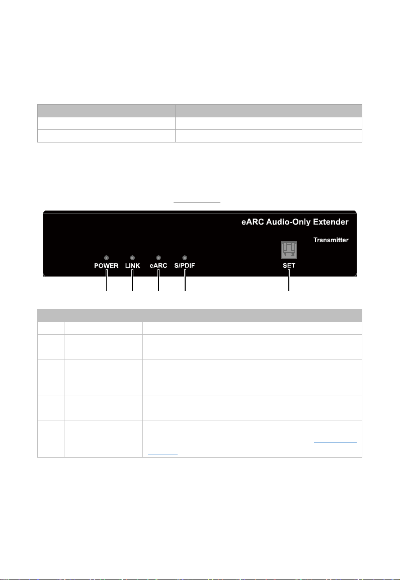
1
POWER LED
On/Off: The device is powered on/off.
Off: No UTP link or link error.
Off: No eARC and ARC audio are being transmitted.
Off: No S/PDIF audio is being transmitted.
For eARC/ARC audio output channel selection.
Note: T568B straight-through Category cable is recommended.
Panel Descriptions
Transmitter
Front Panel
2 LINK LED
3 eARC LED
4 S/PDIF LED
5 SET
On: UTP link is normal.
On: The eARC audio is being transmitted.
Blinking: The ARC audio is being transmitted.
On: The S/PDIF audio is being transmitted.
Note: Detail information, please refer to “DIP Switch
Settings” section.
4
Page 6
Rear Panel
1 2 3 4 5
6
7
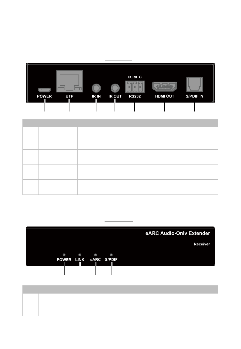
No.
Name
Description
with 5V power source (Such as USB port of display).
2
UTP
Connect to UTP IN port of the receiver.
3
IR IN
Connect to the IR receiver provided.
4
IR OUT
Connect to the IR emitter provided.
upgrading.
6
HDMI OUT
Connect to a display’s eARC/ARC HDMI input port.
7
S/PDIF IN
Connect to a display’s Toslink output port.
1 2 3 4
No.
Name
Description
1
POWER LED
On/Off: The device is powered on/off.
Off: No UTP link or link error.
1 POWER
5 RS232
Receiver
2 LINK LED
Use the provided Micro USB to USB type-A cable to connect
Connect to RS232 enabled device for RS232 pass-through or
Front Panel
On: UTP link is normal.
5
Page 7
No.
Name
Description
3 eARC LED
Off: No eARC and ARC audio are being transmitted.
Off: No S/PDIF audio is being transmitted.
1 2 3 4 5
6
7
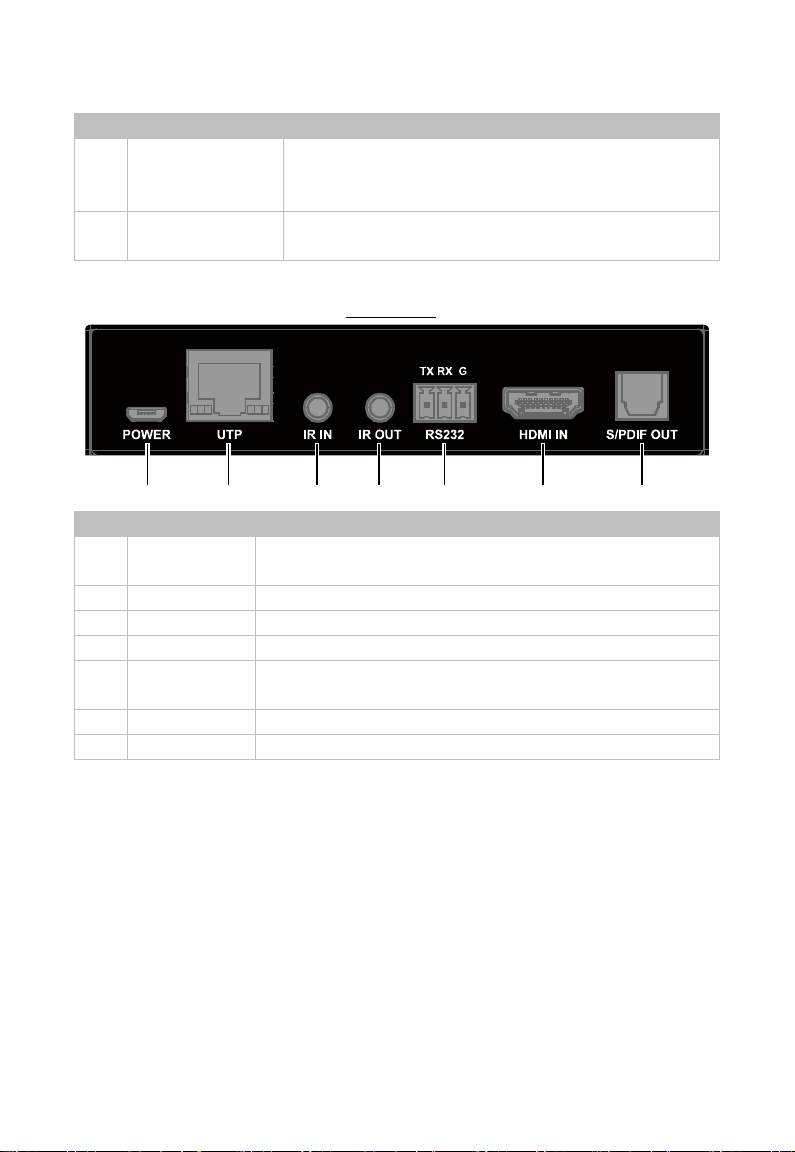
No.
Name
Description
with 5V power source.
2
UTP
Connect to UTP OUT port of the transmitter.
3
IR IN
Connect to the IR receiver provided.
4
IR OUT
Connect to the IR emitter provided.
upgrading.
6
HDMI IN
Connect to an AV receiver’s eARC/ARC HDMI output port.
7
S/PDIF OUT
Connect to an AV receiver’s To s l ink input port.
On: The eARC audio is being transmitted.
Blinking: The ARC audio is being transmitted.
4 S/PDIF LED
1 POWER
5 RS232
On: The S/PDIF audio is being transmitted.
Rear Panel
Use the provided Micro USB to USB type-A cable to connect
Connect to RS232 enabled device for RS232 pass-through or
6
Page 8
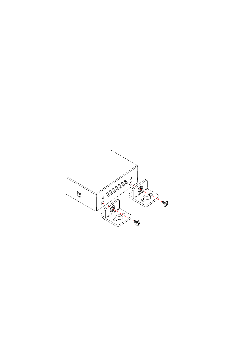
Installation and Wiring
Installation
Warnings:
Before wiring, disconnect the power from the device.
During wiring, connect and disconnect the cables gently.
Steps to install the device:
1. Attach the installation bracket to the enclosure using the screws provided
in the package separately.
2. The bracket is attached to the enclosure as shown.
3. Repeat the steps from 1 to 2 for the other side of the unit.
4. Attach the brackets to the surface you want to hold the unit against using
the screws (provided by others).
5. Repeat the steps from 1 to 4 to install the receiver.
7
Page 9

Wiring
Warnings:
Before wiring, disconnect the power from all devices.
During wiring, connect and disconnect the cables gently.
Note: Ensure the connected display support eARC/ARC function and its
CEC function should be set to enable.
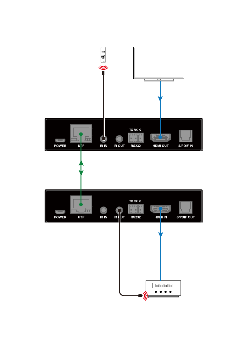
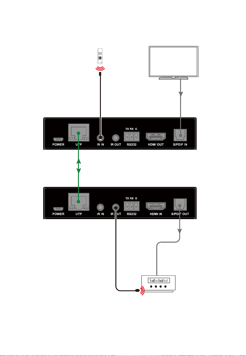
The extender supports two channels to output eARC/ARC audio from the
connected display.
1. Set the DIP switch of transmitter to eARC/ARC or S/PDIF channel (See
“DIP Switch Settings
2. Connect the receiver’s HDMI IN port to an AV Receiver’s eARC/ARC
HDMI output port. Or connect the receiver’s S/PDIF OUT port to an AV
Receiver’s Toslink input port.
3. Connect the transmitter’s HDMI OUT port to a display’s eARC/ARC input
port. Or connect the transmitter’s S/PDIF IN port to a display’s To s l ink
output port.
4. Connect UTP OUT port of the transmitter to UTP IN port of the receiver.
5. Using the provided Micro USB to USB Type-A cables to connect the
transmitter and receiver to 5V power sources.
6. Power on all attached devices. The return audio signal from HDMI OUT
port will be transmitted to HDMI IN port, or the return audio signal from
S/PDIF IN port will be transmitted to S/PDIF OUT port (according to the
selection in step 1).
For additional wiring:
Bi-directional IR pass-through: Connect the provided IR receiver to IR
IN port of the transmitter/receiver, and connect the provided IR emitter to
IR OUT port of the receiver/transmitter. You can control the display at
receiver side or control the AV receiver at transmitter side.
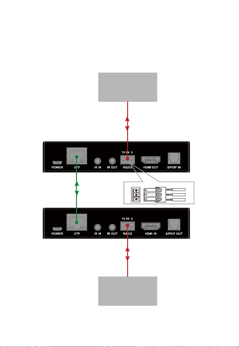
Bi-directional RS232 pass-through: Connect RS232 enabled devices
” section).
8
Page 10

such as PC to RS232 ports of the transmitter and receiver. (See “
Pass-Through” section)
RS232
9
Page 11
Transmitter
Receiver
Cat 5e/6 or above
Receiver Remote
IR Receiver
AV Receiver
IR emitter
eARC/ARC
IN
eARC/ARC
OUT
Display
Figure 1 eARC / ARC Channel
10
Page 12
Transmitter
Receiver
Cat 5e/6 or above
S/PDIF
IN
S/PDIF
OUT
AV Receiver
Display
Receiver Remote
IR Receiver
IR emitter
Figure 2 S/PDIF Channel
11
Page 13

DIP Switch Settings
1 2
Before powering on the kit, using DIP Switch on front panel of the transmitter
to select the channel to output the eARC/ARC audio.
Please refer to the following table to set:
Transmitter Function
1 2
Up - eARC/ARC Channel (default)
Down - S/PDIF Channel
“-“ indicates the position of this DIP switch has no influence on the function.
Note:
1) When select output eARC audio, audio format supported is as follows:
Up to 8ch L-PCM of 24 bit, 192kHz audio;
Support HBR audio formats, such as Dolby True-HD, Dolby Atmos
and DTS-X.
2) When output ARC audio, audio format supported is as follows:
Supports 5.1ch compressed audio, such as Dolby Digital, DTS 5.1,
and Dolby Digital Plus;
Supports 2.0ch uncompressed PCM audio.
3) When output the return audio through S/PDIF port, audio format
supported is as follows:
Supports 5.1ch compressed audio, such as Dolby Digital, DTS 5.1,
and Dolby Digital Plus;
Supports 2.0ch uncompressed PCM audio.
12
Page 14
Transmitter
Receiver
Cat x
RS232 Device
RS232 Device
RX
TX
GND
TX
RX
G
RS232 Port Connected RS232 Devi ce Pins
RS232 Pass-Through
RS232 ports can be used for bi-directional RS232 signal pass-through
between the transmitter and receiver.
13
Page 15

 Loading...