

LG EAY43596801, YP32DVR Schematic
SAFETY PRECAUTIONS
SERVICE WARNING
Only qualified service technicians who are familiar with safety checks and
guidelines should perform service work. Before replacing parts, disconnect power source to protect electrostatically sensitive parts. Do not
attempt to modify any circuit unless so recommended by the manufacturer. When servicing the receiver, use an isolation transformer between
the line cord and power receptacle.
GENERAL GUIDELINES
Perform a final SAFETY CHECK before returning receiver to customer.
Check repaired area for poorly soldered connections, and check entire
circuit board for solder splashes. Check board wiring for pinched wires or
wires contacting any high wattage resistors. Check that all control knobs,
shields, covers, grounds, and mounting hardware have been replaced. Be
sure to replace all insulators and restore proper lead dress.
SAFETY CHECKS FIRE AND SHOCK HAZARD
Cold Leakage Checks for Receivers with Isolated Ground
Unplug the AC cord, connect a jumper across the plug prongs, and turn
the power switch on (if applicable). Use an ohmmeter to measure the
resistance between the jumped AC plug and any exposed metal cabinet
parts such as antenna screw heads, control shafts, or handle brackets.
Exposed metal parts with a return path should measure between 1M ohms
and 5.2M ohms. Parts without a return path must measure infinity.
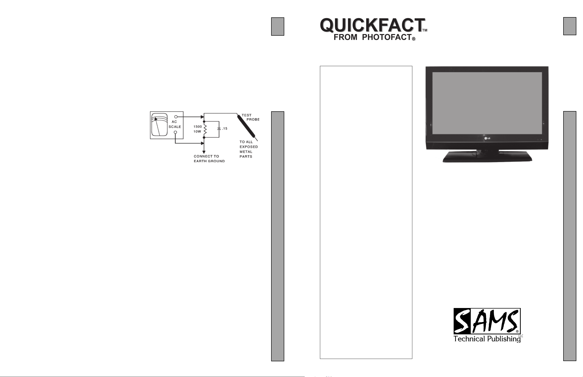
Hot Leakage Current Check
Plug the AC cord directly into an AC outlet. DO NOT use an isolation transformer. Use a 1500 ohms, 10W resistor in parallel with a .15µF capacitor to
connect between any exposed metal parts on the receiver and a good earth
ground. (See figure below.) Use an AC voltmeter with at least 5000 ohms per volt
sensitivity to measure the voltage across the resistor. Check all exposed metal
parts and measure voltage at each point. Voltage measurements should not
exceed .75VAC, 500µA. Any value exceeding this limit constitutes a potential
shock hazard and must be corrected. If the AC plug is not polarized, reverse the
AC plug and repeat exposed metal part voltage measurement at each point.
5388
LCD SERIES
SET 5388
GridTrace Location
Miscellaneous Adjustments ...................... 2
Parts List ................................................... 1
Placement Chart (Resistances) ................. 3
Placement Chart (Voltages) ...................... 3
Safety Precautions .................................... 1
Schematic Component Location .............. 2
Schematic Notes ....................................... 2
Schematics
LCD SERIES
INDEXINDEX
INDEX
INDEXINDEX
Power Supply .................................... 1
Power Supply Schematic ................... 2
5388
Technical Service Data
LG
MODEL 32LC7D (CHASSIS LA73E)
5388
1
The listing of any available replacement part herein in no case constitutes a recommendation, warranty, or guarantee by
SAMS Technical Publishing, LLC as to the quality and suitability of such replacement part. The numbers of the listed parts have
been compiled from information furnished to SAMS Technical Publishing, LLC by the manufacturers of the specific type of
replacement part listed.
Reproduction or use, without express permission, of editorial or pictorial content, in any manner, is prohibited. No patent
liability is assumed with respect to the use of the information contained herein.
© 2008 SAMS Technical Publishing, LLC
9850 E. 30th St.
Indianapolis IN 46229
www.samswebsite.com
MODEL 32LC7D (CHASSIS LA73E)
THIS IS A GREEN PRODUCT
Do not use lead based solder for repair. Use only
green product parts for replacement.
Essential coverage
for servicing an LCD receiver...
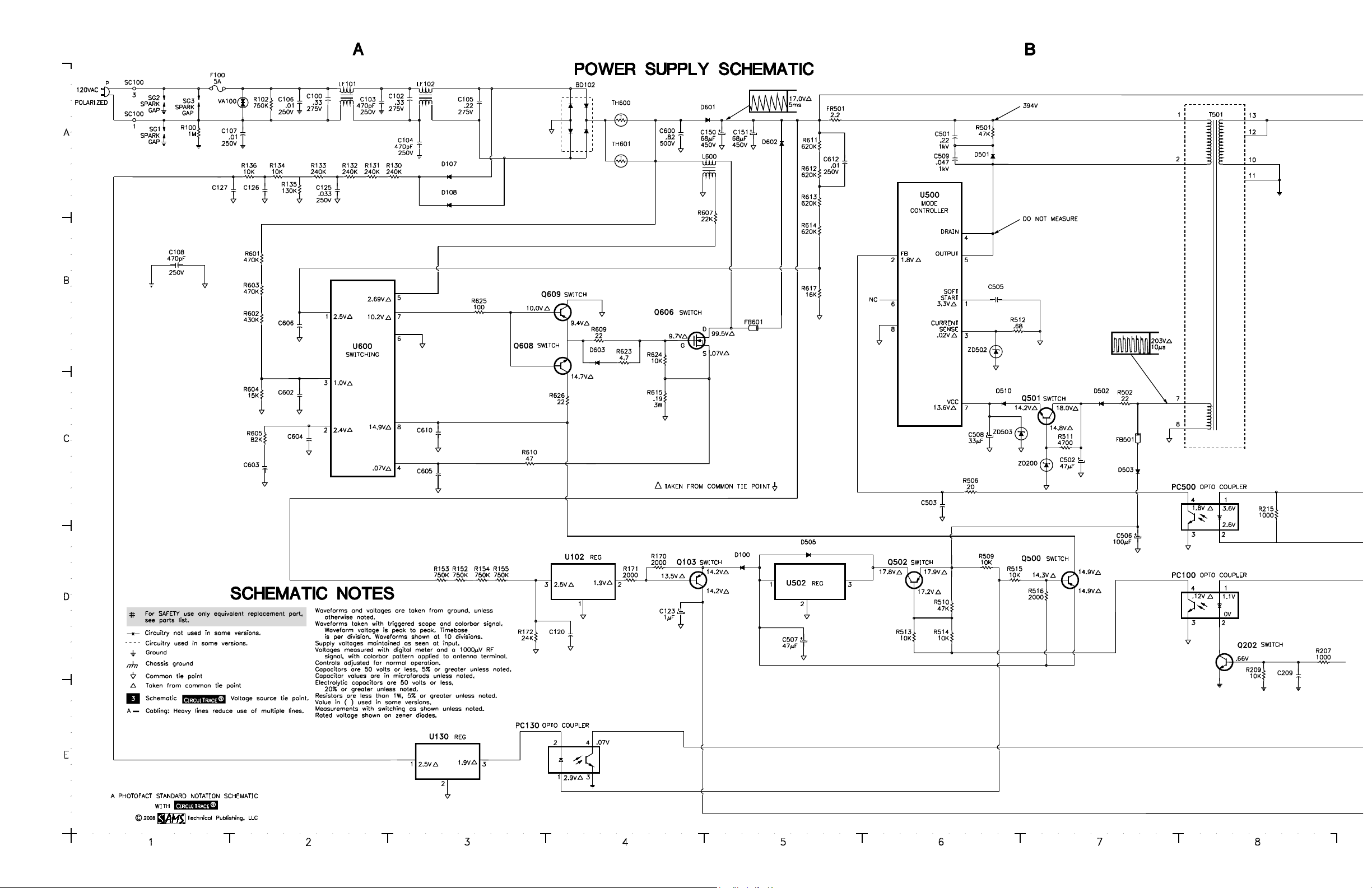
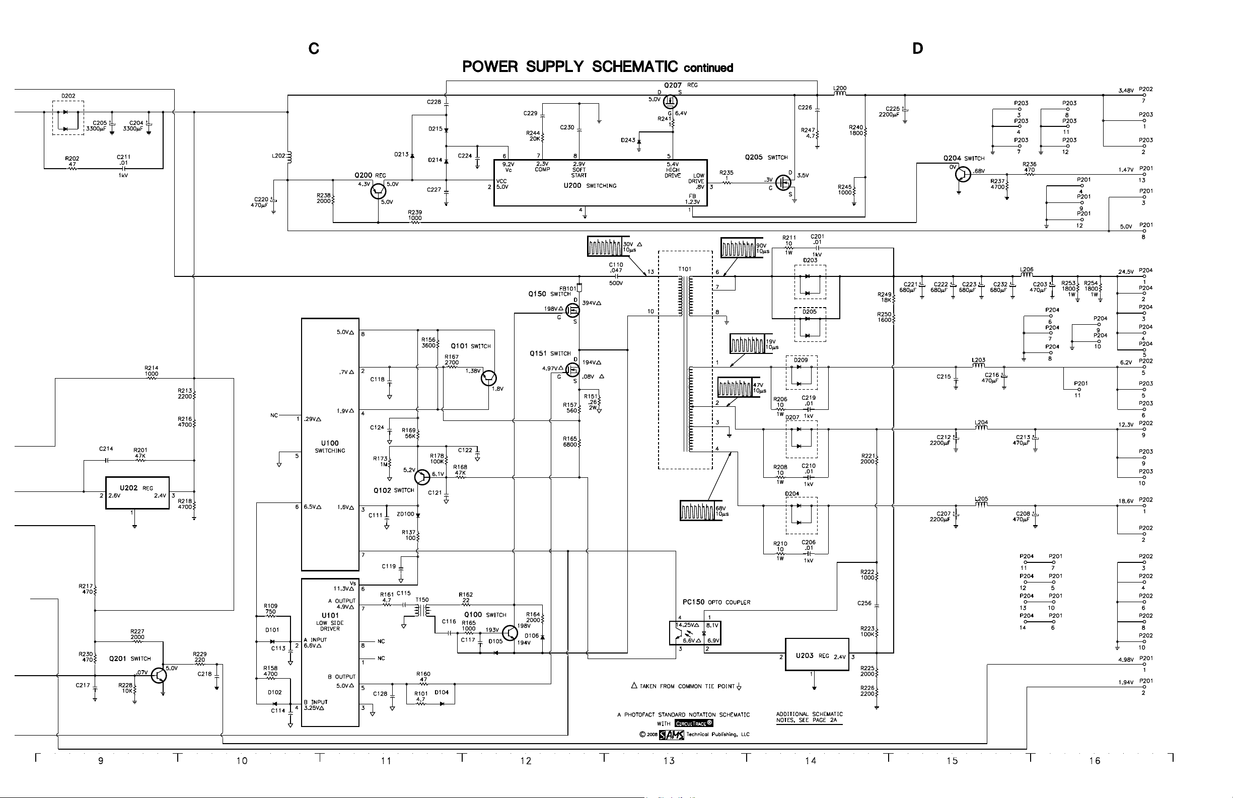
Power Supply Schematic
Miscellaneous adjustments
Placement chart
Parts list
Coverage includes these additional MODELS:
MODELS CHASSIS
32LC7D-UB LA73E
32LC7DC LA73E
32LC7DC-UB LA73E
Printed in the United States of America 5 4 3 2 1 08FP06006
Page 1 SET 5388
!IBCGC|05388X
For a Complete List of Manuals,
Visit www.samswebsite.com
JULY 2008 SET 5388
LG

Page 1 SET 5388
PARTS LIST
Item No. Type No. Mfr. Part No. Notes
BD102 D3SBA60 - -
D100 BAV70WT1 - A4
D101 BAV70WT1 - A4
D102 BAV70WT1 - A4
D104 BAV70WT1 - A4
D105 BAV70WT1 - A4
D106 BAV70WT1 - A4
D107 705S1J - -
D108 705S1J - -
D202 MBRF10100CT - -
D203 MBRD20150CT - -
D204 MBRF10100CT - -
D205 MBRD20150CT - -
D207 MBRF1060CT - -
D209 MBRF1060CT - -
D213 1N4148WS - T4 U3
D214 1N4148WS - T4 U3
D215 1N4148WS - T4 U3
D243 1N4148WS - T4 U3
D501 UF4007 - -
D502 UF1007 - -
D503 UF1007 - -
D505 1N4148WS - T4 U3
D510 1N4148WS - T4 U3
D601 S3V 60 - -
D602 FSU10A60 - -
D603 1N4148WS - T4 U3
PC100 EL817 - -
PC130 EL817 - -
PC150 EL817 - -
PC500 EL817 - -
Q100 MMBT2222AT - 1P
Q101 MMBT2222AT - 1P
Q102 BC850B - 2F
Q103 BC850B - 2F
Q150 STP9NK60Z - -
Q151 STP9NK60Z - -
Q200 BC850B - 2F
Q201 MMBT2222AT - 1P
Q202 MMBT2222AT - 1P
Q204 MMBT2222AT - 1P
Q205 AP62T03GH - -
Q207 AP60T03GH - -
Q500 BC850B - 2F
Q501 MMBT2222AT - 1P
Q502 BC850B - 2F
Q606 STW20NM60 - -
Q608 MMBT2222AT - 1P
Q609 - - SL 2C
U100 001 H26 - -
U101 MIC4428 - -
U102 EA1 - -
U130 EA1 - -
U200 IRU3037GH - -
Item No. Type No. Mfr. Part No. Notes
U202 EA1 - -
U203 EA1 - -
U500 ICE3B1565 - -
U502 KA78L15AZ - -
U600 1D0750 5501A - -
Item No. Function/Rating Mfr. Part No. Notes
C211 .01 1kV - -
F100 Fuse - 5Amp, 250V
FB101 Ferrite Bead - -
FB501 Ferrite Bead - -
FB601 Ferrite Bead - -
L200 - - -
L202 - - -
L203 - - -
L204 - - -
L205 - - -
L206 - - -
L600 Choke - LP-001/SJ0729
LF101 Line Choke - -
LF102 Line Choke - -
T101 SMT - LM-002/SJB-003/SJ/SJ0732
T150 - - DT101
T501 SMT - LS-003/SJ0727
TH600 DSC 15D-15 - -
TH601 DSC 15D-15 - -
VA100 Varistor TVR14621 - -
ZD100 - - WJ
ZD200 1N5245 - -
ZD502 1N5227 - -
ZD503 1N5251 - -
# Display EAJ37543301 LCD
PC Board EBR37277301 Control Key
PC Board EBR38577601 LED
EBR36011401 LED
PC Board (1) EBU38568601 Main
PC Board (2) EBU38099801 Main
# PC Board EAY34795001 Power Supply
EAY36768101 Power Supply
PC Board EBR38575001 Side AV
EBR36010601 Side AV
Power Cord 6410TUW008A AC, Polarized
Remote Control AKB32559904 Assembly
Speakers EAB33496901 8 Ohms, 10W
# For SAFETY use only equivalent replacement part.
(1) Used in MODELS 32LC7D and 32LC7D-UB.
(2) Used in MODELS 32LC7DC and 32LCDC-UB.
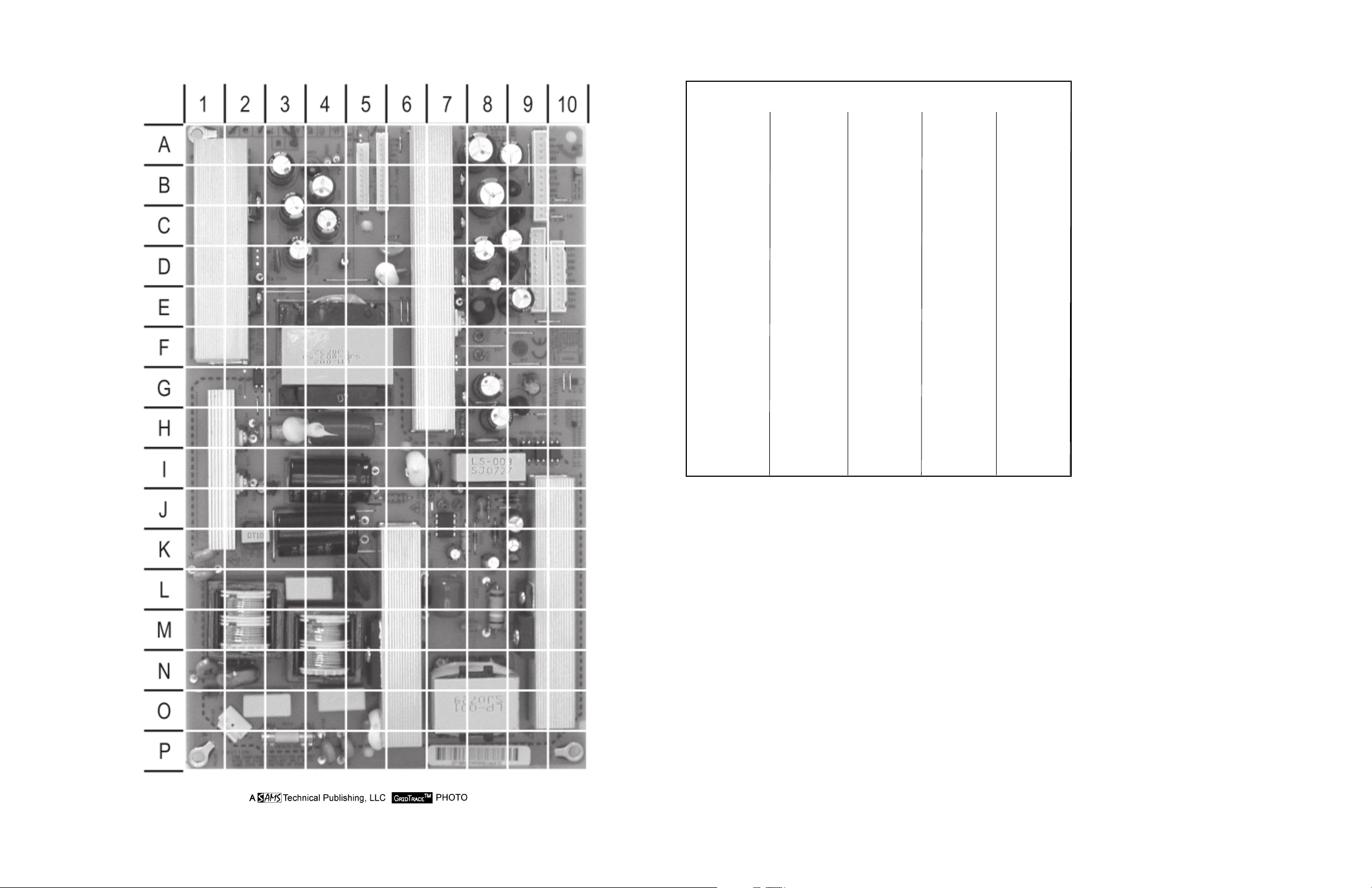
POWER SUPPLY BOARD TOP
POWER SUPPLY BOARD TOP, GRIDTRACE LOCATION GUIDE
SET 5388 Page 1
BD10 M5
C100 O2
C102 L4
C103 L1
C104 P4
C105 O4
C106 P4
C107 N1
C108 K1
C110 H4
C123 I3
C150 J4
C151 I4
C201 D3
C203 B4
C204 H8
C205 G8
C206 C6
C207 A8
C208 A9
C210 D6
C211 G8
C212 B8
C213 C9
C215 D8
C216 D8
C219 D8
C220 G9
C221 B3
C222 A3
C223 D3
C225 E9
C232 C4
C501 I6
C502 K9
C506 J9
C507 K8
C508 K7
C509 I7
C600 L7
C612 M8
D202 G7
D203 B2
D204 B7
D205 E2
D207 C7
D209 D7
D501 I7
D502 K8
D503 J9
D601 L7
D602 L9
F100 P3
FB101 H3
FB501 J8
FB601 L8
FR50 J6
L200 E8
L202 G9
L203 D9
L204 C9
L205 B9
L206 B4
L600 O8
LF101 M2
LF102 M4
P201 A9
P202 D1
P203 D9
PC10 I9
PC13 I1
PC15 G2
PC50 I9
Q150 I2
Q151 H2
Q207 E7
Q606 M9
R100 N1
R102 N2
R151 H3
R202 H7
R206 E7
R208 D5
R210 D4
R211 D2
R253 A4
R254 A4
R501 I6
R502 J8
R512 K7
R615 L8
SC10 O2
T101 F4
T150 K2
T501 I8
TH60 L5
TH60 L5
U500 J7
U502 K9
VA100 N2
ZD20 K9
ZD50 K8
ZD50 K7
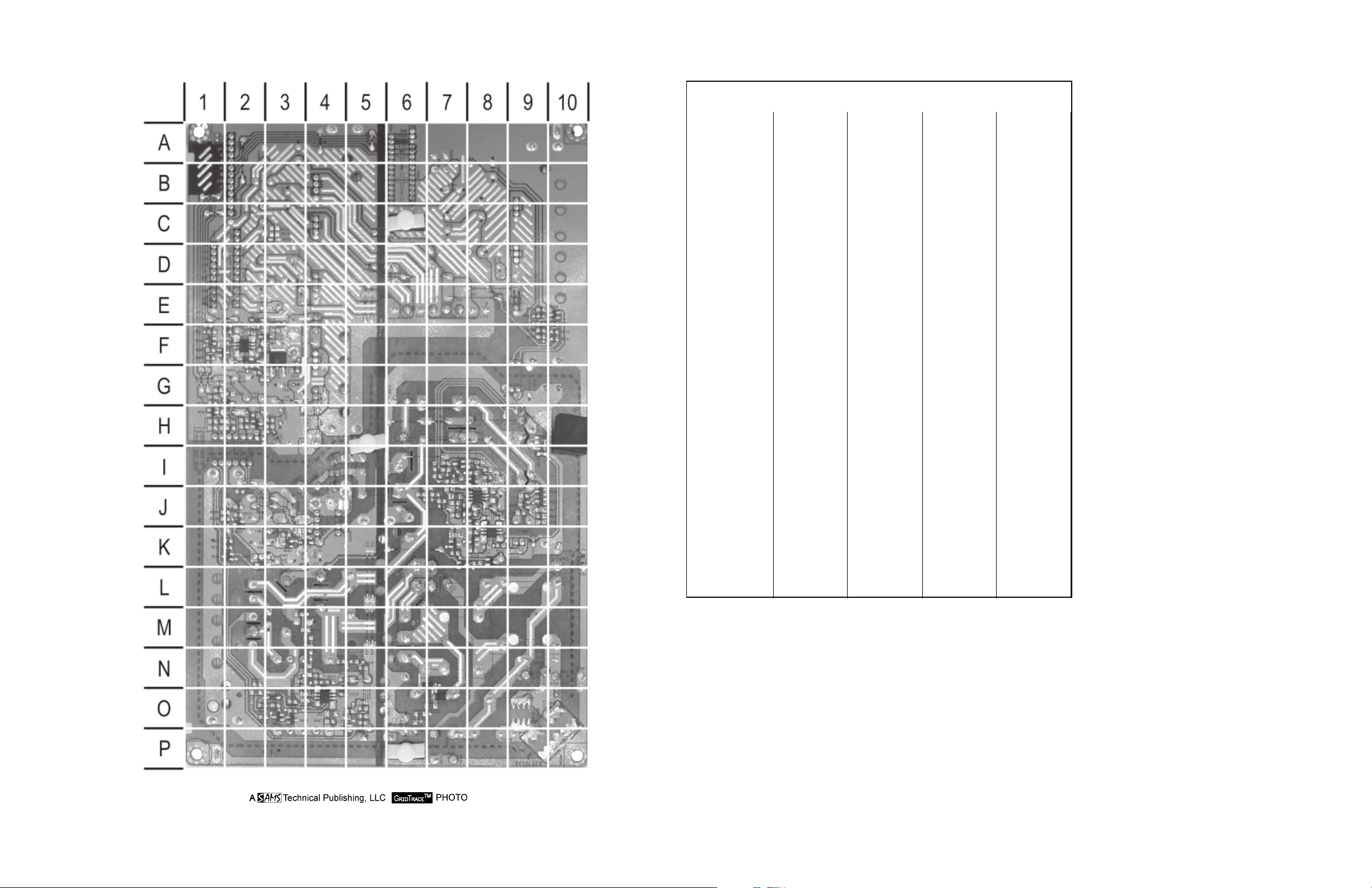
POWER SUPPLY BOARD BOTTOM
POWER SUPPLY BOARD BOTTOM, GRIDTRACE LOCATION GUIDE
C111 J7
C113 J8
C114 K8
C115 K9
C116 J9
C117 J9
C118 J7
C119 J8
C120 K7
C121 I7
C122 I8
C124 I8
C125 O6
C126 O5
C127 O5
C128 K9
C209 G1
C214 H2
C217 H1
C218 G1
C224 F2
C226 F3
C227 F1
C228 F3
C229 G2
C230 F2
C256 E1
C503 K4
C505 K4
C602 N4
C603 N3
C604 O3
C605 O3
C606 N4
C610 O4
D100 K7
D101 J8
D102 K8
D104 H9
D105 J9
D106 J9
D107 O7
D108 N7
D213 E3
D214 E2
D215 F2
D243 F2
D505 K2
D510 K4
D603 O3
Q100 J9
Q101 I8
Q102 I7
Q103 K8
Q200 F1
Q201 H1
Q202 G2
Q204 F1
Q205 F2
Q500 K2
Q501 K3
Q502 J2
Q608 O3
Q609 O3
R101 I9
R109 K8
R130 O7
R131 O6
R132 O6
R133 O5
R134 O5
R135 O5
R136 O5
R137 J8
R152 J7
R153 J6
R154 J7
R155 J7
R156 I8
R157 I7
R158 K8
R160 I9
R161 K8
R162 J9
R163 J9
R164 J9
R165 I7
R167 J7
R168 I7
R169 I8
R170 K8
R171 K7
R172 K7
R173 I8
R201 H2
R207 G1
R209 G2
R213 H3
R214 H2
R215 H2
R216 H3
R217 H2
R218 H2
R221 F10
R222 F10
R223 E9
R225 E9
R226 E9
R227 H1
R228 H1
R229 G1
R230 H1
R235 G3
R236 F1
R237 F1
R238 F1
R239 F1
R240 F2
R241 F2
R244 G2
R245 F2
R247 G3
R249 F9
R250 F9
R506 J2
R509 J2
R510 J2
R511 K3
R513 K2
R514 K2
R515 K2
R516 K2
R601 N4
R602 N5
R603 N5
R604 N4
R605 N3
R607 O4
R609 O3
R610 O3
R611 M3
R612 M4
R613 M4
R614 M4
R617 M4
R623 O3
R624 N2
R625 O3
R626 O2
U100 J8
U101 K8
U102 K7
U130 O5
U200 F2
U202 H2
U203 E1
U600 O4
ZD10 J7
SET 5388 Page 1
Page 2 SET 5388
SET 5388 Page 2
 Loading...