

Page 1

2013 LED/LCD TV
Copyright © 2013 LG Electronics. Inc. All rights reserved.
Only for training and service purposes
LGE Internal Use Only
Engineering guide
< Applicable Model : Mid-end Platform >
XXLA74*-Z*
XXLA71*-Z*
XXLA69/66*-Z*
XXLA64/62/61*-Z*
XXLN57*-Z*
1/ 88
Page 2

◈ CONTENT ◈
Copyright © 2013 LG Electronics. Inc. All rights reserved.
Only for training and service purposes
LGE Internal Use Only
1. New features
2. Main PCBs
3. Block Diagrams, IIC Map
4. Structure of TV set and connection of sub ass’ys
5. New sub ass’ys
- Instruction of new sub ass’ys
6. Adjust way of new features
7. Repair guide
2/ 88
Page 3

EPI Interface
Copyright © 2013 LG Electronics. Inc. All rights reserved.
Only for training and service purposes
LGE Internal Use Only
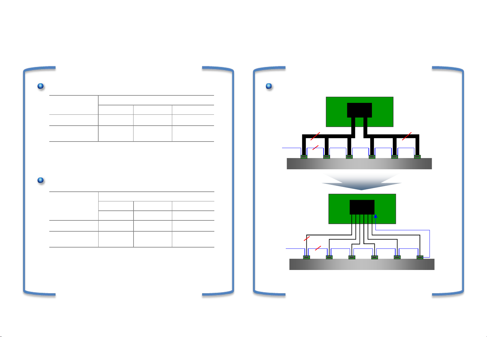
EPI(Embedded Point-Point Interface)
Features
• Point-Point topology (support 2 Pair option)
• CDR (Clock Data Recovery)
• Bandwidth up to 1.85Gbps/pair
at FHD 120Hz 10 bit application
• Lock signal cascading and feedback to T-Con
• Embedded Control Data
Merits
VCC
TCON
LOCK
2
1
Figure1. Topology
• Better reliability on common noise
• No data skew and better EMI margin
• Fewer lines than mini-LVDS
• Slim PCB design
3/ 88
Page 4
EPI Interface (mini-LVDS vs. EPI)
Copyright © 2013 LG Electronics. Inc. All rights reserved.
Only for training and service purposes
LGE Internal Use Only
Comparison
HF mini-LVDS
HF mini-
LVDS
No. of Signal 36 36 72
Connector
60Hz 120Hz 240Hz
60pin
(2ea)
-Difficult to upgrade bandwidth limit
-Multiple number of wires needed for higher bandwidth
EPI (Embedded clock P-to-P Interface)
EPI
No. of Signal 12 12 32
Connector -
-Better reliability on common noise
-No data skew. Better EMI margin
-Lower cost ( Cable, Connector )
-Slim S-PCB design (14mm Æ 10mm) helps slimmer TV
60Hz 120Hz 240Hz
960ch 960ch 720ch
FHD (10bit)
60pin
(2ea)
FHD (10bit)
50 pin
(2ea)
80pin
(2ea)
70pin
(2ea)
What to change
LCM (T-con to S-Driver IC)
HF mini-LVDS
18
VCC
1
EPI
2
VCC
* Bandwidth Capability
- FHD 120Hz 10Bit : 594Mbps@36Lines → 1.65Gbps@12Lines
- FHD 240Hz 10Bit : 594Mbps@72Lines → 1.25Gbps@32Lines
1
TCON
18
(FHD 120Hz)
TCON
LOCK
(FHD 120Hz)
4/ 88
Page 5
EPI Interface (mini-LVDS vs. EPI)
Copyright © 2013 LG Electronics. Inc. All rights reserved.
Only for training and service purposes
LGE Internal Use Only
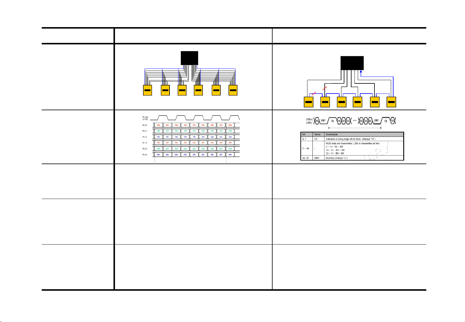
HF mini-LVDS EPI
Topology
Protocol
Features
@10bit, FHD120
Merit
TCON
• Multi Drop
• Data rate: 660Mbps
• External clock
• Simple structure
• Standardization
TCON
2
1
• Point to Point
• Data rate : 1.8Gbps
• Embedded clock, Control
• Fewer Lines : 12
• Embedded clock
: low EMI, Clock skew free
Lock
Demerit
• Too many lines : 36
• Clock skew
• EMI due to clock lines
• Bandwidth limit
• Easy to PCB design
• Transmission Overhead
: 4bit delimiter
5/ 88
Page 6
NFC (Near field communication)
Copyright © 2013 LG Electronics. Inc. All rights reserved.
Only for training and service purposes
LGE Internal Use Only
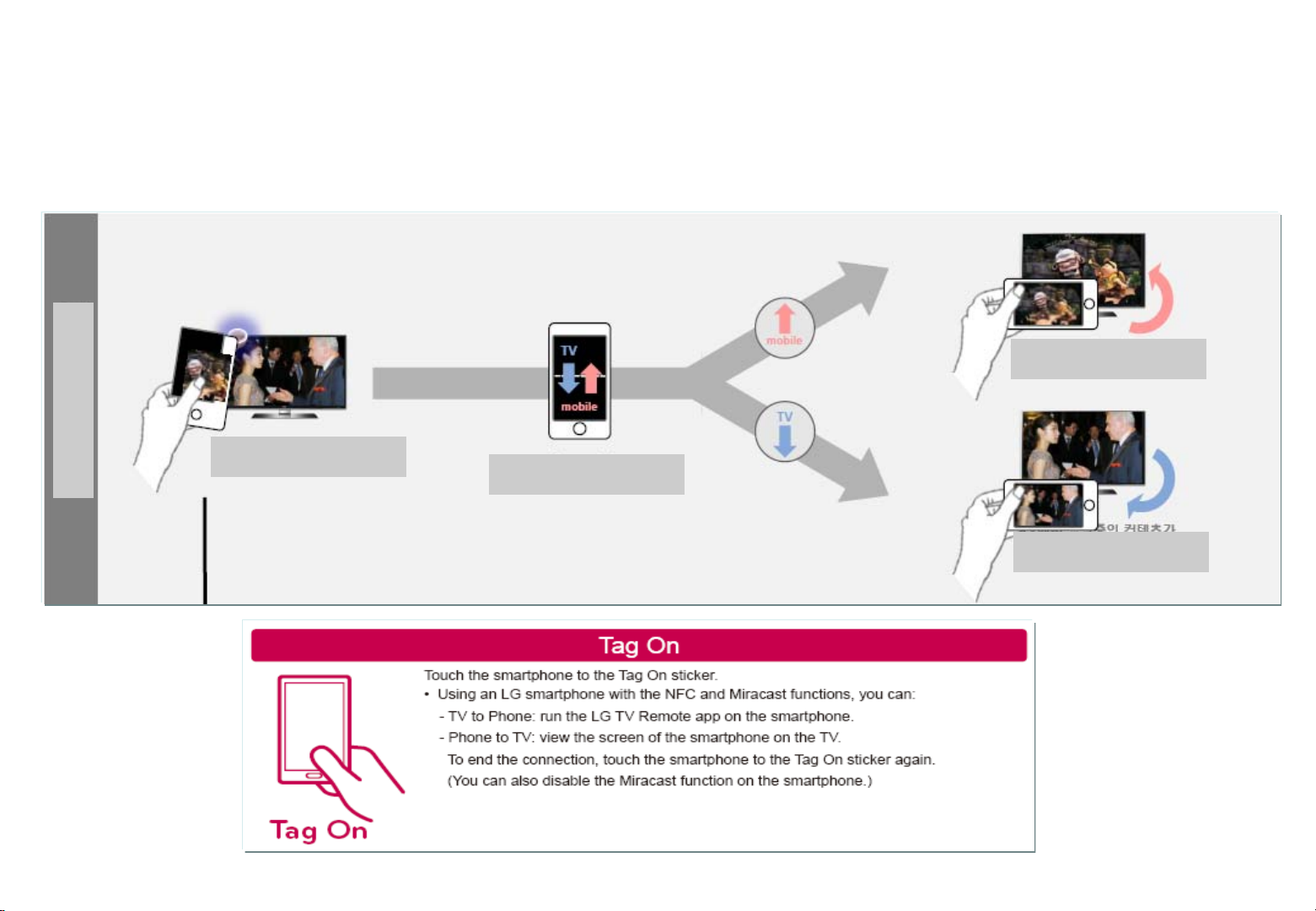
Near field communication (NFC) is a set of standards for smartphones and similar devices to establish radio communication
with each other by touching them together or bringing them into close proximity, usually no more than a few centimetres.
Present and anticipated applications include contactless transactions, data exchange, and simplified setup of more complex
communications such as Wi-Fi. Communication is also possible between an NFC device and an unpowered NFC chip, called
a "tag".
From Smart phone
to TV
User Action Area
Samrt phone close to
NFC Tag
Player choose
From TV
to Smart phone
6/ 88
Page 7
Main PCB for Broadband
Copyright © 2013 LG Electronics. Inc. All rights reserved.
Only for training and service purposes
LGE Internal Use Only
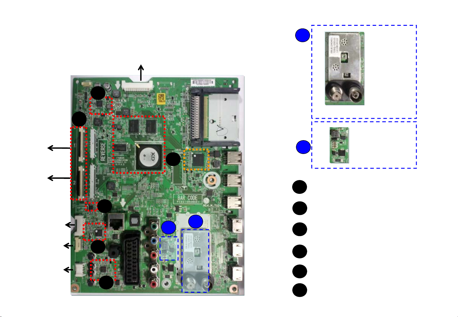
xxLA660S-Zx
To PSU
3
5
Main + TCON all in one
1
Chassis : LD33B
PCB P/No : EAX64797003
S
model
To module
6
WIFI/BT
Key+IR
2
Front Spk
4
2
Only S model
1
LNB IC Block
Main processor, DDR Memory
1
eMMC Memory
Micom for Key/IR sensing
2
1
2
3
4
5
6
PMIC
Audio AMP
EPI Wafer
Level shifter
7/ 88
Page 8
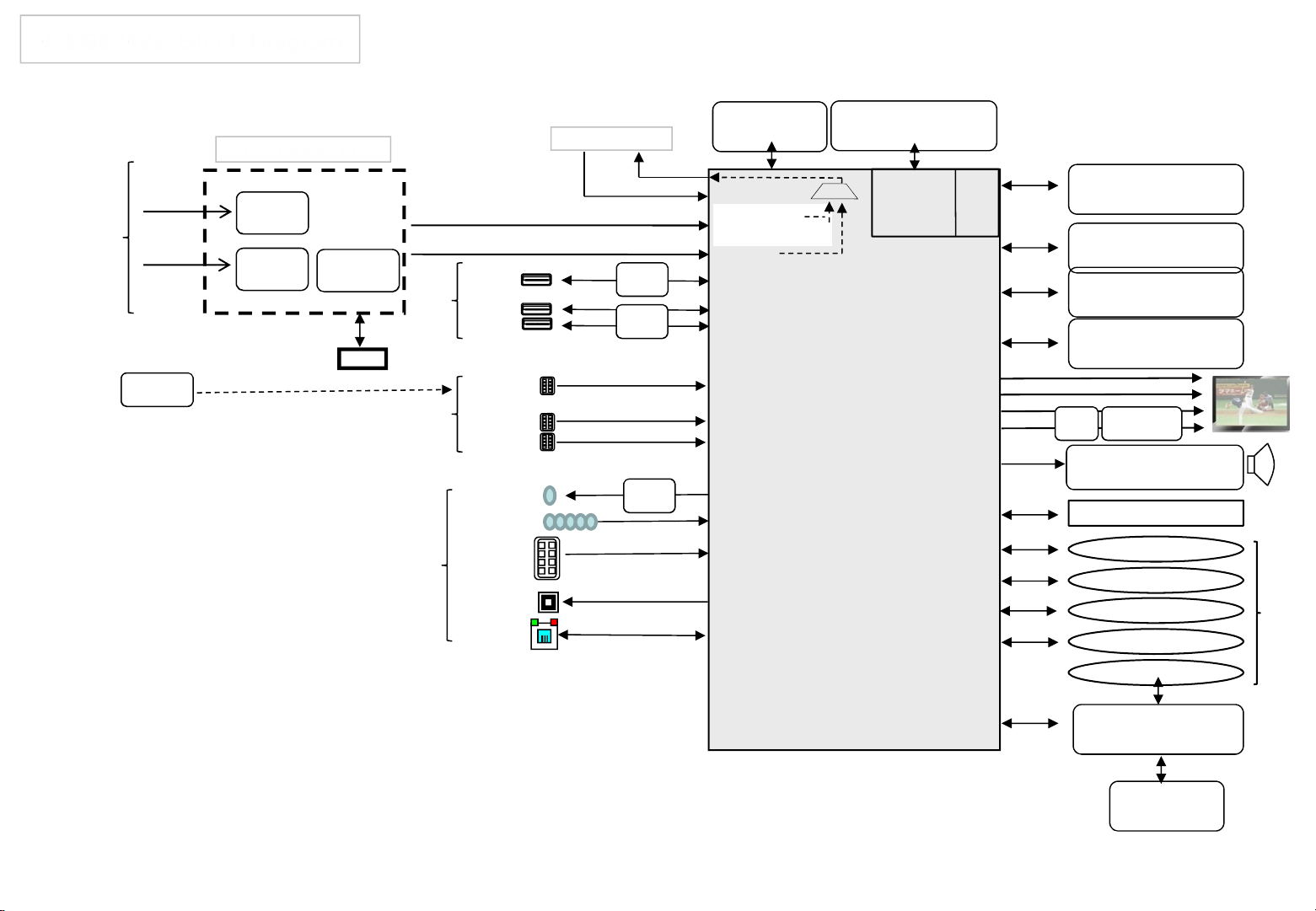
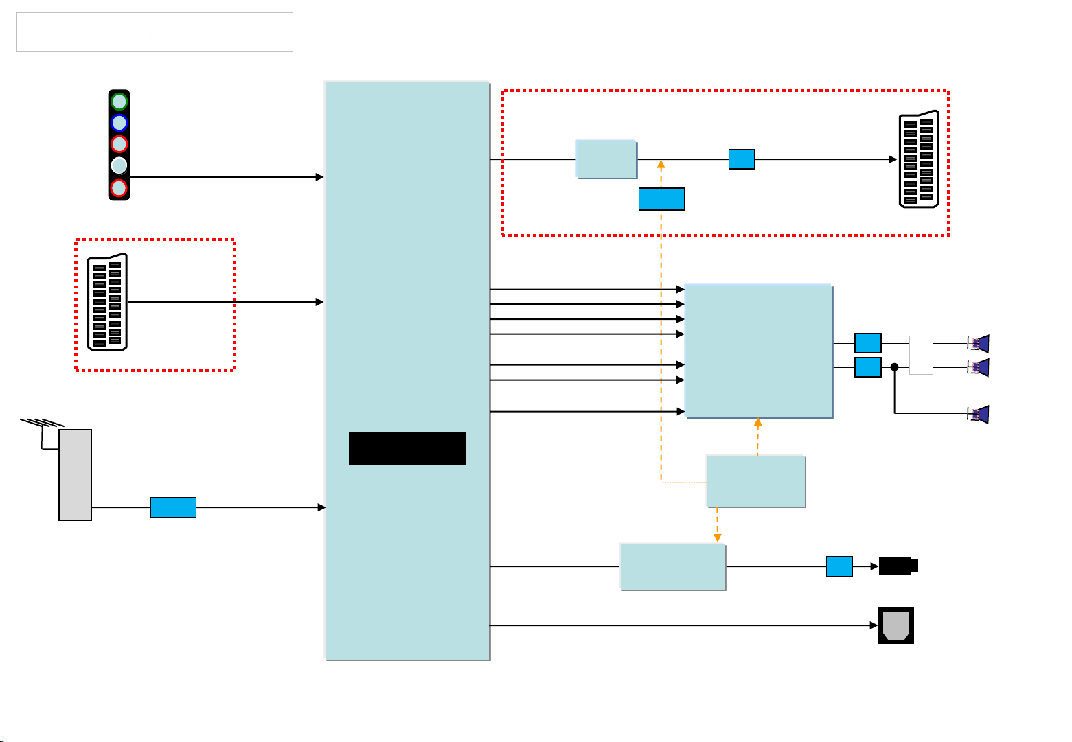
1. LGE2122 Block Diagram
Copyright © 2013 LG Electronics. Inc. All rights reserved.
Only for training and service purposes
LGE Internal Use Only
Cable
R
E
A
DVB-S
R
(H)
MHL 1A
SIL1392
MHL : I2C 4
Air/
T/C/S2 Without ATV
TUNER
(T/C/A)
TUNER
(S2)
DVB-S : I2C 4
MHL
DEMOD
(S2)
LNB
Tuner : I2C 6
USB1
S
(HDD)
I
USB2
D
USB3
E
HDMI1
S
I
HDMI2
D
HDMI3
E
H/P
AV/COMP
R
SCART
E
A
R
OPTIC
LAN
CI Slot
P_TS
IF (+/-)
P_TS
OCP
2.5A
OCP
1A
AMP
TI
P_TS
X_TAL
27MHz
T/C Demod
Analog Demod
P_TS
USB
HDMI
MUX
CVBS/YPbPr
CVBS/RGB
SPDIF OUT
ETHERNET
DDR3 1600 X 16
(512MB X 2EA)
LGE 2122
A B
I2C 5
I2C 1
LVDS
EPI
I2C 2
I2S Out
I2C 1
I2C 1
UART
KEY
USB_WIFI
DDR3 1600 X 16
(256MB X 1EA)
SYSTEM EEPROM
(256Kb)
HDCP EEPROM
(16Kb)
eMMC
(4GB)
51P
41P
50P
50P
IR
PM ICLEVEL
SHIFTER
Audio AMP
(NTP7513)
LOCAL DIMMING
BLUTOOTH
IR / NFC
KEY
WIFI
LOGO LIGHT
SUB
ASSY
I2C 3
Sub Micom
(RENESAS R5F1000G)
X_TAL
32.768KHz
Page 9
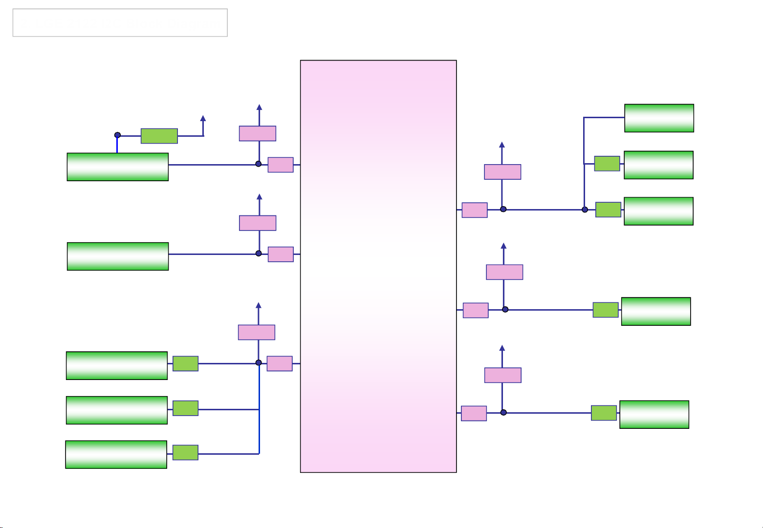
2. LGE 2122 I2C Block Diagram
Copyright © 2013 LG Electronics. Inc. All rights reserved.
Only for training and service purposes
LGE Internal Use Only
IC3000
Renesas MICOM
IC7700
PMIC
IC8101
NTP7513(AMP)
3.3KΩ
+3.5V_ST
100Ω
+3.3V_Normal
2.7KΩ
33Ω
+3.3V_Normal
2.7KΩ
33Ω
+3.3V_Normal
1.2KΩ
33Ω
IC105
LGE 2122
I2C_SDA3
I2C_SCL3
I2C_SDA2
I2C_SCL2
I2C_SDA1
I2C_SCL1
I2C_SDA4
I2C_SCL4
I2C_SDA5
I2C_SCL5
+3.3V_Normal
2.7KΩ
33Ω
+3.3V_Normal
2.7KΩ
33Ω
+3.3V_Normal
2.7KΩ
33Ω
22Ω
33Ω
IC3304
MHL
LNB
TUNER(S)
IC100
NVRAM
P7600
Local dimming
IC101
HDCP EEPROM
33Ω
22Ω
I2C_SDA6
I2C_SCL6
33Ω
33Ω
TUNER(D)
Page 10
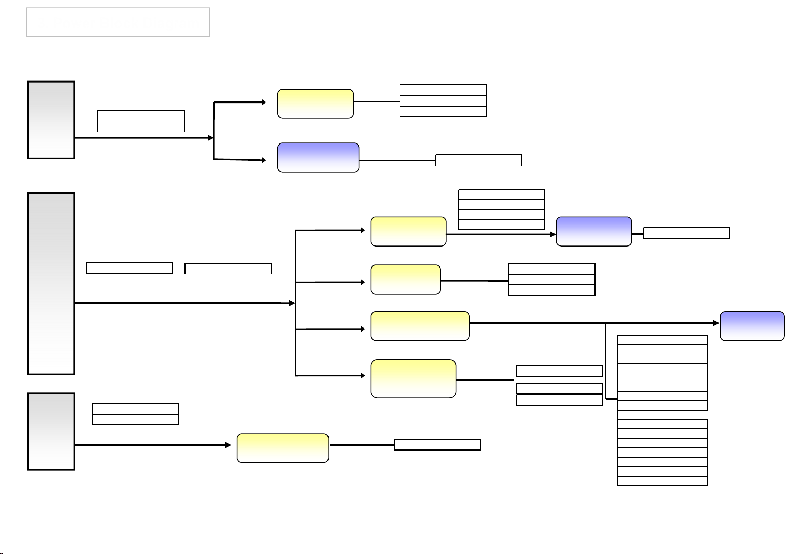
3. Power Block Diagram
(
)
y
(
)
)
)
L
)
)
A
(
)
Q)
T
)
Copyright © 2013 LG Electronics. Inc. All rights reserved.
Only for training and service purposes
LGE Internal Use Only
3.5V
12V
24V
MICOM(VDD)
IR A'ssy
PANEL_VCC
PANEL_POWER
NTP_7400(PVDD1)
NTP_7400(PVDD2)
AMP
+12V_LNB
LNB option
1.5V DDR
5V USB 3A
3A
1.23V
2A
MTK (DDRV)
DDR(VDD)
DDR(VDDQ)
TUNER(+1.23V)
5V Normal
3A
1.2V Core
6A
3.3V Noraml
4A
5V USB
1CH DCDC 4A
2CH OCP 1.2A
USB1(DVR Max 1.5A
HDMI_EEPROM
RGB_EEPROM
CI (+5V_CI_ON)
TUNER(+5V_TU)
MTK(AVDD12_LVDS)
MTK
MTK(VCCK)
AVDD_
USB_WIFI
USB2(Max 1.2A)
USB3(Max 1.2A)
3.3V DAC
MTK(AVDD33_DAC)
SPDIF
IR A'ss
M_REMOTE
HDCP EEPROM
NVRAM
DVDD3V3
MTK
MTK (AVDD33_AADC
MTK (AVDD3V3
MTK(AVDD3V3_MEMPL
MTK(AVDD3V3_LVDS
MTK(AVDD33_STB
UDIO AMP
EARPHONE AMP
VCC
EMMC
EMMC(VCC
UNER(+3.3V_TU)
1.8V_TU
Page 11
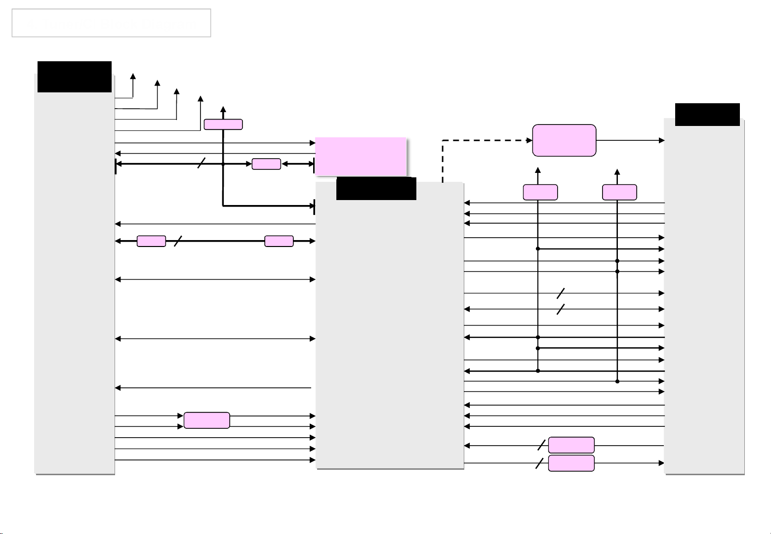
4. Tuner/CI Block Diagram
Copyright © 2013 LG Electronics. Inc. All rights reserved.
Only for training and service purposes
LGE Internal Use Only
TDSQG501D
[+3.3V_S2_DEMOD] 32
[+3.3V_TUNER] 5
[+.1.8V_TUNER] 7
[+1.23V_S2_DEMOD] 30
[S2_F22_OUTPUT] 33
[LNB] 36
[S2_SCL] 34
[S2_SDA] 35
+3.3V_D_Demod
+3.3V_TU
+1.8_TU
+1.23V_D_Demod
LNB_TX
LNB_OUT
I2C_SCL4
+3.3V_NORMAL
3.3K Ω
22 Ω
10 [TONECTRL]
2 [LNB]
7 [SCL]
8 [SDA]
I2C_SDA4
[RESET] 2 AG24 [ADIN6_SRV]
[SLC] 3
[SDA] 4
[ERROR] 16
[SYNC] 17
[VALID] 18
[MCLK] 19
/TU_RESET1
IC2_SDA6
IC2_SCL6
FE_DEMOD1_TS_SYNC
FE_DEMOD1_TS_VAL
FE_DEMOD1_TS_CLK
33 Ω33Ω
FE_DEMOD1_TS_DATA [0-7]
[D0-7] 20-27
[S2_RESET] 31 AM18 [ADIN7_SRV]
[T/C_DIF[P]] 10
[T/C_DIF[N]] 11
IF_P
IF_N
/S2_RESET
Attenuator
TUNER_SIF(for T2/C/S)
ADCINP_DEMOD
ADCINN_DEMOD
AM27 [ADCINP_DEMOD]
AN27 [ADCINN_DEMOD]
TU_CVBS(for
T2/C/S)
IF_AGC
A8303SESTR-TB
IC6900
LGE 2122
AP6 [S CL3]
AR6 [S DA3]
AF19[OPCTRL1]
AJ19 [OPCTRL0]
R29 [DEMOD_TSSYNC]
P27 [DEMOD_TSVAL]
P30 [DEMOD_TSCLK]
[DEMOD_TSDATA0-7]
LNB
T34[DEMOD_RST]
P34[PVR_TSDATA1]
P33[PVR_TSDATA0]
R33[PVR_TSSYNC]
R35[CI_TSDATA0]
PCM_5V_CTL
CI 5V
Power detect
+5V_CI_ON
VCC
+5V_CI_ON +3.3V_NORMAL
F28[TCON12]
L33[SPI_CLK]
L30[SPI_CLK1]
M31[CI_TSCLK] CARD_EN1
N34[SPI_DATA]
N35[SPI_CLE]
[GPIO0-14]
[GPIO26-33]
N36[CI_INT]
R36[CI_TSVAL]
R37[CI_TSSYNC]
CI_ADDR[0-14] CI_A_ADDR[0-14]
CI_DATA[0-7] CI_A_DATA[0-7]
MTK5398_TS_CLK
R3[PVR_TSCLK]
[GPIO34-41] TS_OUT[0-7]
[GPIO18-25] TS_IN[0-7]
MTK5398_TS_VAL
MTK5398_TS_SYNC
MT5398_TS_IN[0-7] CI_TS_DATA[0-7]
MT5398_TS_OUT[0-7] CI_MDI[0-7]
10K Ω
/CI_CD1
/CI_CD2
CI_VS1
/PCM_CE1
/PCM_CE2
/PCM_IOWR
/PCM_IORD
PCM_RST
/PCM_WAIT
PCM_INPACK
/PCM_A_REG
/PCM_IRQA
/PCM_OE
/PCM_WE
47 Ω
47 Ω
47K Ω
CI_TS_CLK
CI_TS_VAL
CI_TS_SYNC
CI_DET1
CI_DET2
VS1M27[PVR_TS_VAL]
CARD_EN2
IOWD
IORD
ADDR[0-14]
DAT[0-7]
CI_RESET
CI_WAIT
INPACK
REG
/IRQA
O_EN
WR_EN
TS_OUT_CLK
TS_OUT_VAL
TS_OUT_SYNC
CI Slot
Page 12

5. Video/Audio In Block Diagram
Copyright © 2013 LG Electronics. Inc. All rights reserved.
Only for training and service purposes
LGE Internal Use Only
JK501
SCART
COMP1_Y/AV1_CVBS
COMP1_Pb
COMP1_Pr
COMP1/AV1/DVI_L_IN
COMP1/AV1/DVI_R_IN
SC_CVBS_IN
SC_ID/FB
SC_R/G/B
SC_L/R_IN
Jack Side
SoC Side
COMP1_Y/AV1_CVBS_SOC
COMP1_Pb_SOC
COMP1_Pb_SOC
COMP1/AV1/DVI_L_IN_SOC
COMP1/AV1/DVI_R_IN_SOC
SC_CVBS_IN_SOC
SC_FB_SOC
SC_R/G/B_SOC
SC_L/R_IN_SOC
[CVBS2P]
[PB0P]
[PR0P]
[AIN4_L_AADC]
[AIN4_R_AADC]
LGE 2122
[CVBS3P]
[ADIN0_SRV, SOY1]
[PR1P, PB1P, Y1P]
[AIN1_L/R_AADC]
JK4600
Tuner
TU_CVBS
TUNER_SIF, IF_P/N
Parallel TS / ERROR,VAL,SYNC,CLK
TU_CVBS
TUNER_SIF, IF_P/N
Parallel TS / ERROR,VAL,SYNC,CLK
[CVBS1P]
[MPXP, ADCINP_DEMOD, ADCINN_DEMOD]
Page 13
6. Audio Out Block Diagram
Copyright © 2013 LG Electronics. Inc. All rights reserved.
Only for training and service purposes
LGE Internal Use Only
COMP1/AV1/DVI_L_IN_SOC
COMP1/AV1/DVI_R_IN_SOC
JK501
SCART
[AIN4_L_AADC]
[AIN4_R_AADC]
[AL1_ADAC]
[AR1_ADAC]
SCART_L/Rout
IC6000
AZ4580MTR
OP AMP
Mute CTRL
(TR)
SCART_MUTE
LPF
SCART
DTV/MNT_L/R_OUT
JK4600
DVB only
JK4600
Tuner
SC_L_IN / SC_R_IN
DVB only
TR BUF
TUNER_SIF
[AIN1_L_AADC]
[AIN1_R_AADC]
LGE 2122
[MPXP]
[AOMCLK]
[AOSDATA0]
[AOLRCK]
[AOBCK]
[STB_SDA]
[STB_SCL]
[OPCTRL4]
[AL0_ADAC]
[AR0_ADAC]
[ASPDIF0]
AUD_MASTER_CLK
AUD_LRCH
AUD_LRCK
AUD_SCK
I2C_SDA1
I2C_SCL1
AMP_RESET_N
HP_L/ROUT_MAIN
SPDIF_OUT
IC6100
TPA6138A2PWR
HP AMP
IC8101
Audio AMP
NTP7513
AMP_MUTE
IC3000
MICOM
SIDE_HP_MUTE
HP_L/ROUT_AMP
LPF
LPF
LPF
JK3700
JK3602
4P WAFER
SPEAKER_L
SPEAKER_R
WOOFER
HEAD PHONE
Page 14
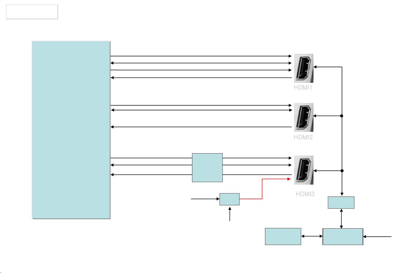
7. HDMI
Copyright © 2013 LG Electronics. Inc. All rights reserved.
Only for training and service purposes
LGE Internal Use Only
DDC_SCL_1_SOC
DDC_SDA_1_SOC
HDMI_ARC
TMDS Link 8bits
HDMI1
LGE 2122
DDC_SCL_2_JACK
DDC_SDA_2_JACK
TMDS Link 8bits
I2C_SCL4
I2C_SDA4
TMDS Link 8bits
SIL1292
5V_MHL
OCP
MHL_DET
DDC_SCL_3_JACK
DDC_SDA_3_JACK
TMDS Link or MHL Link
5V_BUS
X-tal
32.768kHz
HDMI2
HDMI3
CEC_REMOTE
Q3001
HDMI_CEC
RENESAS
MICOM
WOL_CTL
Page 15
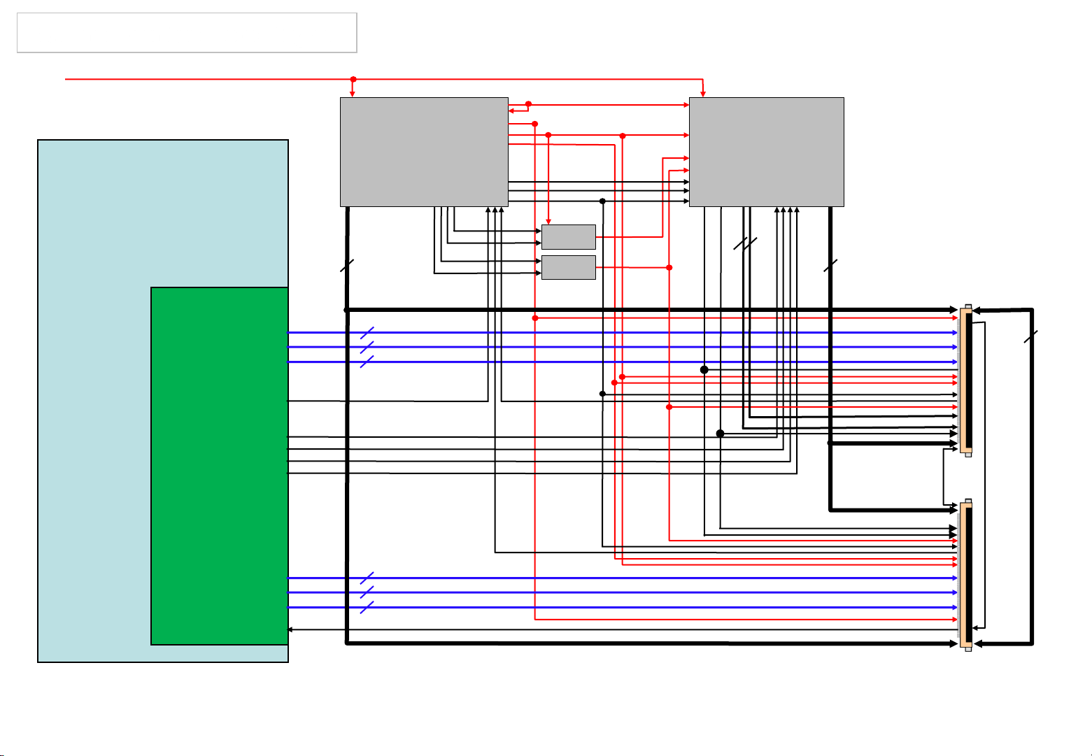
8. Panel Interface Block Diagram
Copyright © 2013 LG Electronics. Inc. All rights reserved.
Only for training and service purposes
LGE Internal Use Only
PANEL_VCC
(+12V)
LGE 2122
EPI Tx
Block
VCC
VCC1.8
VDD
PMIC
H_VDD
TPS65178
VCOM_P
SWP
CTRLP
6
GMA4/GMA5/GAM7/GMA12/GMA14/ GMA15
2
2
2
SWN
CTRLN
EPI CH1 +/EPI CH2 +/EPI CH3 +/-
VCOM_DYN VCOMLFB
VCOM_N
TR/
Diode
TR/
Diode
VCOM_LOOP
VGH
VGL
VCOM
EO
GST
GCLK
MCLK
Level Shift
TPS65198
2
VGL_I
GIP_RST
VST
CLK1_I~CLK6_I
2
6
50Pin X 2
6
GMA1/GMA3/GAM9/GMA10/GMA16/GMA18
VGH_EVEN/VGH_ODD
VGH_F/VGH_R
EPI_LOCK3
Z_Out
VCOMRFB
2
2
2
GMA4/GMA5/GAM7/GMA12/GMA14/GMA15
EPI CH4 +/EPI CH5 +/EPI CH6 +/-
EPI_LOCK6_SOURCE EPI_LOCK6
Page 16
9. PMIC & Level Shift Bloc Diagram
Copyright © 2013 LG Electronics. Inc. All rights reserved.
Only for training and service purposes
LGE Internal Use Only
PANEL_VCC
Boost Converter
Buck 1 converter(VCC)
Buck 2 converter(Vcore)
Buck 3 converter(HVdd)
Buck 4 converter(VCC18)
Positive Charge Pump Controller
Negative Charge Pump Controller
6-Ch Gamma Buffer(DAC output)
Vcom reference & gain
Reset
Vdd
VCC
Vcore
HVdd
VCC18
SWN
CTRLN
SWP
CTRLP
GAM4/5/7/12/14/15
VCOM_P
VCOM_N
VCOM_LOOP
PMIC_RESET
TR/
Diode
TR/
Diode
Level Shift
TPS65198
VGL
VGH
TPS65178
PMIC
Page 17
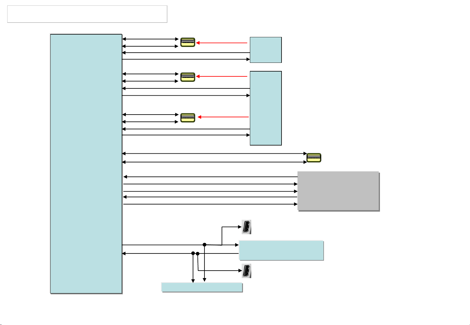
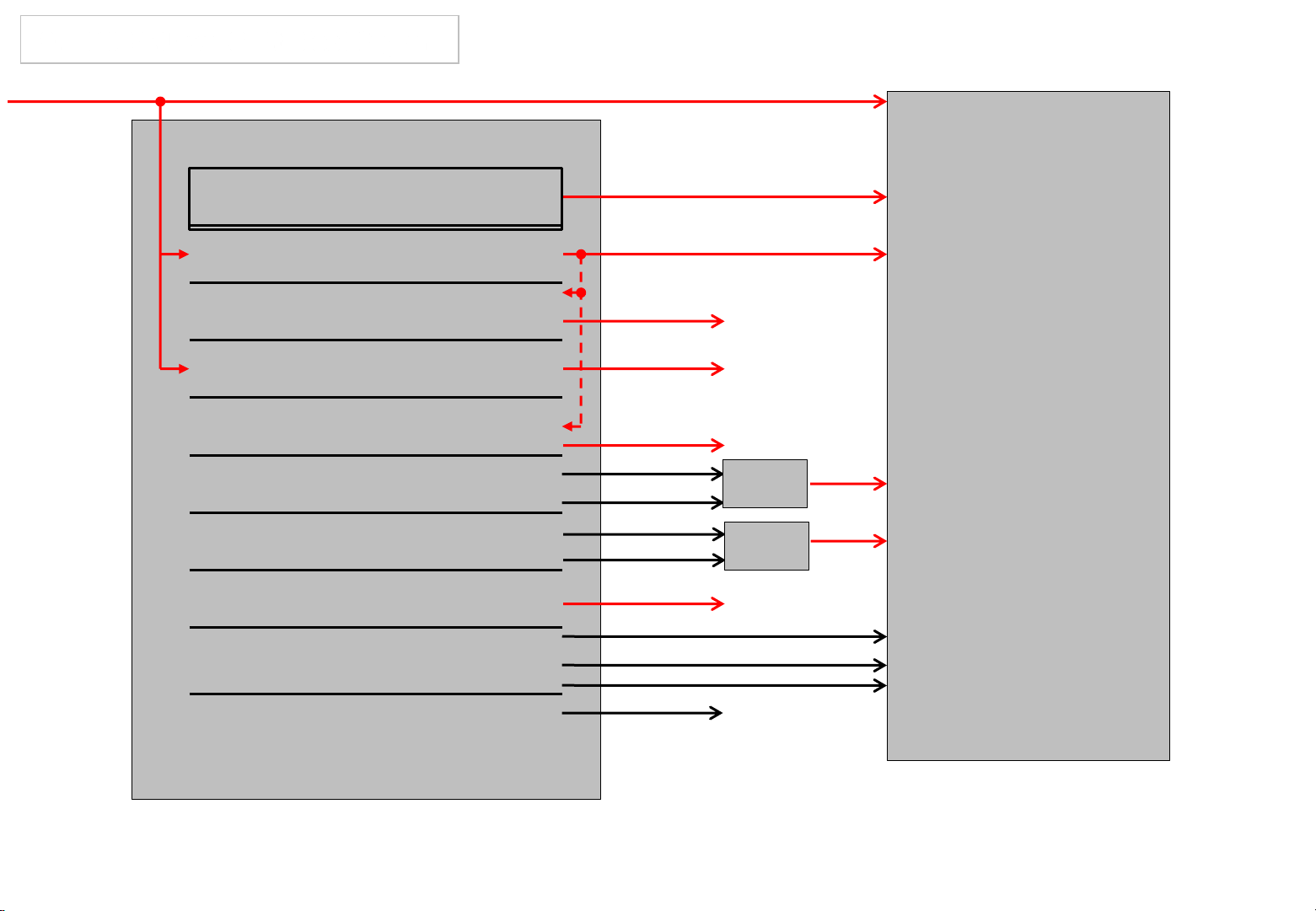
10. USB / WIFI / M-REMOTE / UART
Copyright © 2013 LG Electronics. Inc. All rights reserved.
Only for training and service purposes
LGE Internal Use Only
[USB_DM_P2]
[USB_DP_P2]
[GPIO43]
[GPIO46]
[USB_DM_P1]
[USB_DP_P1]
[GPIO42]
[TCON12]
[USB_DM_P0]
[USB_DP_P0]
[GPIO44]
[ADIN2_SRV]
[USB_DM_P3]
[USB_DP_P3]
[U1RX]
[U1TX]
[ADIN4_SRV]
[OPCTRL49]
[OPCTRL50]
USB_DM1
USB_DP1
/USB_OCD1
USB_CTL1
USB_DM2
USB_DP2
/USB_OCD2
USB_CTL2
USB_DM3
USB_DP3
/USB_OCD3
USB_CTL3
WIFI_DM
WIFI_DP
USB1
USB2
USB3
+5V_USB_1
+5V_USB_2
+5V_USB_3
M_REMOTE_RX
M_REMOTE_TX
M_RFModule_RESET
RTS
CTS
OCP
OCP
USB_WIFI
Motion Remote
Receiver
[U0TX]
[U0RX]
LGE 2122
SOC_TX
SOC_RX
RENESAS MICOM
HDMI2
4Pin debugging
wafer
HDMI3
Page 18
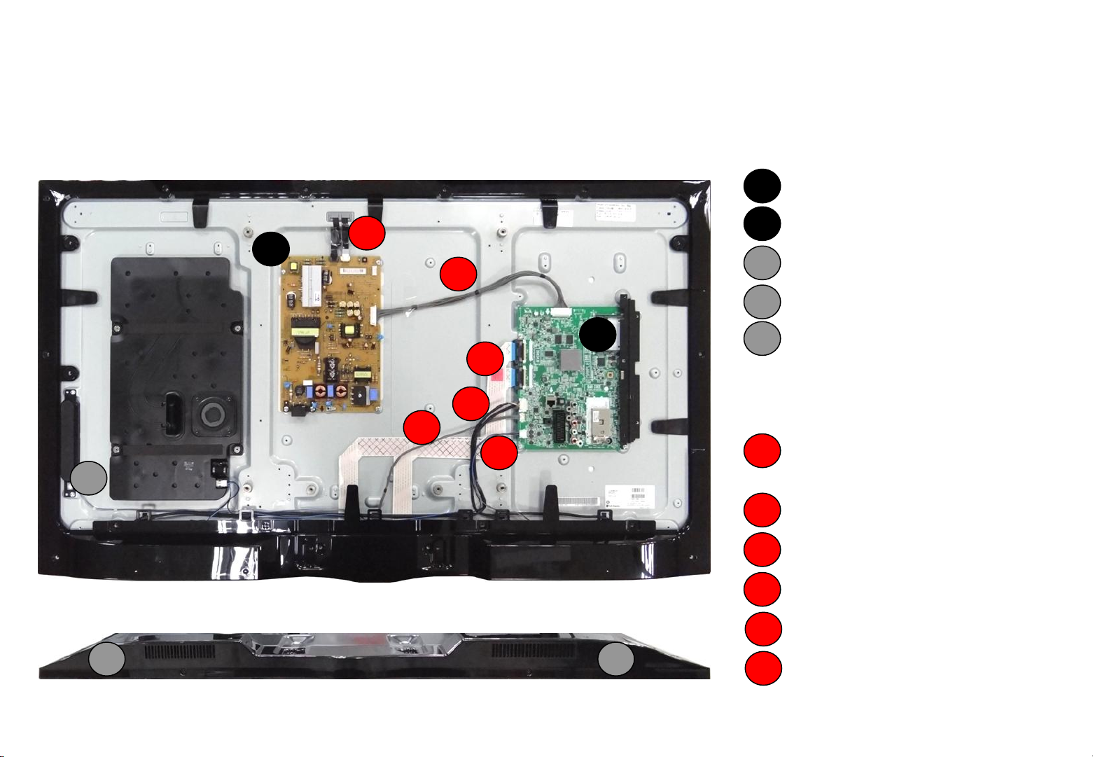
Interconnection - 1
Copyright © 2013 LG Electronics. Inc. All rights reserved.
Only for training and service purposes
LGE Internal Use Only
47LA660S-ZA
[PCBs]
3
2
3
4
1
5
2
6
1
1
2
3
4
5
Main PCB
Power Board
Local key Assy
RF Assy
WIFI Assy
[Cables]
1
Main / LPB 24Pin + Local
Dimming Cable
Main / Module EPI Cable
2
50& 50Pin
LED driver / PSU
3
4
IR 8Pin Cable
4 5
1 / 88
5
WiFi 6Pin + RF 8Pin Cable
6
SPK Cable
Page 19
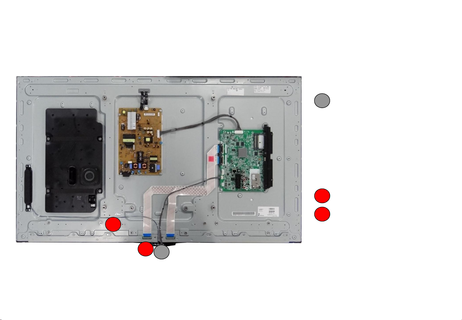
Interconnection - 2
Copyright © 2013 LG Electronics. Inc. All rights reserved.
Only for training and service purposes
LGE Internal Use Only
47LA660S-ZA
[PCBs]
7
8
6
6
IR Assy
[Cables]
IR to Local Key 3Pin Cable
7
8
IR to Logo Assy 4Pin Cable
2 / 88
Page 20

Introductions of 13Y RF ass’y + Magic Remote control
Copyright © 2013 LG Electronics. Inc. All rights reserved.
Only for training and service purposes
LGE Internal Use Only
1. System
2. Remote Buttons
3. MR13 Block Diagram
4. Function List
5. Pairing/Un-pairing Method
3 / 88
Page 21

1. System
Copyright © 2013 LG Electronics. Inc. All rights reserved.
Only for training and service purposes
LGE Internal Use Only
RF
UART
or USB
RF Receiver
Remote
Pairing Information Transmission (Send to TV after Paired)
• Static Calibration Data (Bypass only)
• Remote FW ver. (Save also in Receiver)
• BD_ADDR (Save also in Receiver)
• Pairing Information Transmission Sequence
• When it is paired, the remote sends packets(pairing success, F/W version, BD_ADDR) to the receiver.
• The receiver sends the pairing success packet to TV directly.
• F/W version and BD_ADDR packets are just saved on the receiver.
• The receiver sends F/W version or BD_ADDR packet to TV when it is required.
Motion Data Transmission
• Period : 7.5msec
• Motion Data : gyro, accelerometer
Voice Data Transmission
• Period : 10msec
• Voice sampling : 16khz 16bit
TV
4 / 88
Page 22
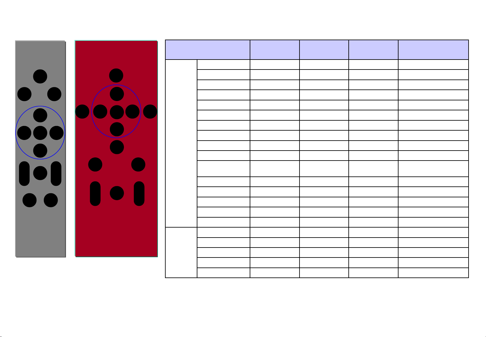
2. Remote Buttons (M4 vs. MR13)
Copyright © 2013 LG Electronics. Inc. All rights reserved.
Only for training and service purposes
LGE Internal Use Only
POWER
BACK HOME
↑
OK
← →
BACK SMART
POWER
↑
OK
← →
↓
VOICE
↓
Screen RMT
Q.MENU
MUTE
MUTE
VOL CH
3D MYAPPS
3D
VOL CH
M4 Remote MR13 Remote
Phsical
Buttons
Logical
Buttons
BUTTON
POWER 0x08 NONE Y IR only
BACK 0x28 0x8028 Y
SMART 0x7C 0x807C Y
← 0x07 0x8007 Y
→ 0x06 0x8006 Y
↑ 0x40 0x8040 Y
↓ 0x41 0x8041 Y
OK 0x75 0x8044 Y
VOICE 0xDE 0x808B Y = VOICE_START
3D 0xDC 0x80DC Y
Screen RMT
/ Q.MENU
CH + 0x00 0x8000 Y
CH - 0x01 0x8001 Y
VOL + 0x02 0x8002 Y
VOL - 0x03 0x8003 Y
MUTE 0x09 0x8009 Y
AUTO_WAKEUP X 0x800C
VOICE_START X 0x800A
VOICE_STOP X 0x800D
POINT_START X 0x803E
POINT_STOP X 0x803F
RF Unpaired
IR_CODE
0xDE
RF Paired
RF_CODE
0x80DE
IR continuous
repeat
Y
ETC.
5 / 88
Page 23

3. MR13 Block Diagram
Copyright © 2013 LG Electronics. Inc. All rights reserved.
Only for training and service purposes
LGE Internal Use Only
MPU-6150
(Gyro+ACC)
(Invensense)
512Kb
(Serial F/M)
Key Button
( 4 x 4 )
Antenna
Partron
X-tal
24 MHz
Wheel
Encoder
I2C ch1
BCM20733M A2
(BROADCOM)
Bluetooth 3.0
Power Management
I2S
I2C ch2
IR Emitter1
IR Emitter2
(Voice Scene IR)
Voice
WM8950
(Wolfson)
Codec(ADC )
MIC.
(Knowles)
4-mode Only
Antenna
BCM20702M
(BROADCOM)
Bluetooth 4.0
SPI
512Kbit
(Serial Flash)
X-tal
20 MHz
UART
AA x 2 Battery
DC-DC Boost
TI TPS61097
SOT23-5
2.8V LDO
uP0108NEC5-28
SC70
2.8V LDO
uP0108NEC5-28
Bluetooth Remote control
SC70
Connector
Bluetooth Receiver
6 / 88
Page 24

4. Function list
Copyright © 2013 LG Electronics. Inc. All rights reserved.
Only for training and service purposes
LGE Internal Use Only
Remocon
주요 Item
IC Manufacturer Function
Voice Codec WM8950 Wolfson 16KHz Sampling of Audio data
Voice
MEMS Mic. SPU0414HR5H Knowles Sensing Voice
Motion
Sensor
Gyro Sensor
+
Accelerometer
MPU-6150 Invensense
Sensing angular velocity of X, Y, Z-axis
Sensing device tilt (Pitch & Roll angle)
RF Antenna SDBTPTR3015 Partron
RF
+
X-tal 24MHz Partron
Wireless communication
Micom
RF + Micom BCM20733A2 Broadcom
DC-DC Converter TPS61097 TI Battery Boost up Regulator
LDO1 uP0108NEC5-28 uPI RF, Gyro, Accelerometer Power Supply
LDO2 uP0108NEC5-28 uPI Audio Codec, Mic. Power Supply
7 / 88
Page 25

5. RF Pairing / Un-pairing Method
Copyright © 2013 LG Electronics. Inc. All rights reserved.
Only for training and service purposes
LGE Internal Use Only
Method Description
• When do pairing, the remote
should make pairing request IR
signal(0x75) to TV.
RF Pairing
RF Unpairing
Method1
– If unpaired, just press "OK" button.
– If paired, press "OK" button after
unpairing.
Method 2 (Repairing)
– Press “BACK" button for 5 sec.
Press “BACK" button and “SMART" button
at the same time for 5 sec.
• When TV receive the IR signal, it
should send "pairing request
packet" to the RF receiver.
• After pairing success, the remote
should blink LED for some time and
TV send "pairing success packet"
back to TV.
• When remote try to unpairing, it
doesn’t care about state of
receiver(stand alone).
• When remote try to unpairing, it
doesn’t care about state of
receiver(stand alone).
• After unpairing, all pairing
information should be erased.
• After unpairing, LED should be
blinked for 3sec.
• The remote just becomes to IR
mode.
8 / 88
Page 26

Introductions of 13Y WIFI built in ass’y
Copyright © 2013 LG Electronics. Inc. All rights reserved.
Only for training and service purposes
LGE Internal Use Only
1. Wi-Fi built in Ass’y feature
2. Wi-Fi built in Ass’y
specification
9 / 88
Page 27

WIFI Built in ass’y feature
Copyright © 2013 LG Electronics. Inc. All rights reserved.
Only for training and service purposes
LGE Internal Use Only
Block diagram
30
48
3.3V
Wafer
6pin 1.25mm
USB
DP, DN
GND
WOL
3.3V 1.2V
DCDC
EUP3010
- Pin map
USB
DP, DN
Crystal
20MHz
3.3V 1.2V
BCM43236B
RX/TX
RX/TX
Switch
DM3030
Switch
DM3030
10 / 88
Antenna
2.4G/5G
Antenna
2.4G/5G
PIN USB interface
1 Vcc
2 DM
3 DP
4 GND
5 WOW
6 NC
Page 28

WIFI Built in ass’y Specification
Copyright © 2013 LG Electronics. Inc. All rights reserved.
Only for training and service purposes
LGE Internal Use Only
11 / 88
Page 29

Widevine & HDCP 2.0 & NETFLX
Copyright © 2013 LG Electronics. Inc. All rights reserved.
Only for training and service purposes
LGE Internal Use Only
Contents
표지
1. Widevine?
2. HDCP 2.0 & NETFLIX?
3. DTCP?
4. Changed BOM
2012. 12. 08
LCD TV
LCD TV R&D Lab / HW1 team
12 / 88
Page 30

1. Widevine?
Copyright © 2013 LG Electronics. Inc. All rights reserved.
Only for training and service purposes
LGE Internal Use Only
[Widevine]
Widevine is the Solution(Library) offering Adaptive Streaming and DRM.
In BBTV, when special CP do service, this module is required key.
Currently CP which is requested to widevine, is typically Australian Bigpond Live and
North American CinemaNow.
Furthermore, because the future will be the spread of CP, widevine key download for the
global model should be applied to production.
(Because operation unique key should be downloaded for Widevine , Widevine key
dowmload by NSU is impossible.)
[Widevine Key]
Widevine Key is unique data stored TV for using Widevine.
13 / 88
Page 31

2. HDCP 2.0 & NETFLIX?
Copyright © 2013 LG Electronics. Inc. All rights reserved.
Only for training and service purposes
LGE Internal Use Only
HDCP
High-bandwidth Digital Content Protection
Protect high-value digital motion pictures, television programs and audio
against unauthorized interception and copying between a digital set top box or
digital video recorder and a digital TV or PC.
Specification developed by Intel Corporation to protect digital entertainment
across the DVI/HDMI interface.
Why HDCP2.0?
HDCP revision 2.0 supports a broader range of wired and wireless interfaces.
Netflix
the services maintain a huge selection of movies and latest releases and offer
DVD rentals via mail & online streaming.
14 / 88
Page 32

3. DTCP?
Copyright © 2013 LG Electronics. Inc. All rights reserved.
Only for training and service purposes
LGE Internal Use Only
[DTCP]
The Digital Transmission Content Protection Specification defines a cryptogrphic
protocol for protecting audio/video entertainment content from unauthorized copying,
intercepting, and tampering as it traverses digital transmission mechanisms such as a
high-performance serial bus that conforms to the IEEE 1394-1995 standard. Only
legitimate entertainment content delivered to a source device via another approved copy
protection system (such as the DVD Content Scrambling System) will be protected by this
protection system.
[Three cryptographic Keys]
• Authentication Key which is formed as a result of authentication and used to protect the
exchange keys.
•Exchage Key which is used to set up and protect content streams.
•Content Key which is used to encrpt the content being exchanged.
15 / 88
Page 33

4. Changed BOM
Copyright © 2013 LG Electronics. Inc. All rights reserved.
Only for training and service purposes
LGE Internal Use Only
As-Was Current
Changed Item
: Separate HDCP check box.
- HDCP 2.0 Tx
- HDCP 2.0 Rx
- HDCP 1.4 Rx
16 / 88
Page 34

Contents of LCD TV Standard Repair Process
Copyright © 2013 LG Electronics. Inc. All rights reserved.
Only for training and service purposes
LGE Internal Use Only
No. Error symptom (High category) Error symptom (Mid category) Page Remarks
1
2 No video/No audio 2
3 Video error, video lag/stop, fail tunning 3, 4
4 Color error 5
5
6
7
8
9 Wrecked audio/discontinuation/noise 10
10
A. Video error
B. Power error
C. Audio error
D. Function error
No video/Normal audio 1
Vertical/Horizontal bar, residual image, light
spot, external device color error
No power 7
Off when on, off while viewing, power auto
on/off
No audio/Normal video 9
No response in remote controller, key error,
recording error, memory error
6
8
11
11 External device recognition error 12
12 E. Noise Circuit noise, mechanical noise 13
13 F. Exterior error Exterior defect 14
14 G. Network error Connection defect / Network speed low 15
First of all, Check whether there is SVC Bulletin in GCSC System for these model.
17 / 88
Page 35

Contents of LCD TV Standard Repair Process Detail Technical Manual
Copyright © 2013 LG Electronics. Inc. All rights reserved.
Only for training and service purposes
LGE Internal Use Only
No. Error symptom Content Page Remarks
1
2 LED driver B+ 24V measuring method A2
A. Video error_ No video/Normal audio
3 Check White Balance value A3
4 Power Board voltage measuring method A4
6
A. Video error_ No video/Video lag/stop
7 LCD-TV Version checking method A7
9
10 Tuner Checking Part A9
A. Video error_Color error
11
12 Adjustment Test pattern - ADJ Key A12
13
14
15 Adjustment Test pattern - ADJ Key A12
A. Video error_Vertical/Horizontal bar,
residual image, light spot
Check LCD back light with naked eye A1
TUNER input signal strength checking method A6
LCD TV connection diagram A8
Check Link Cable (LVDS) reconnection
condition
LCD TV connection diagram A8
Check Link Cable (LVDS) reconnection
condition
A10
A11
A10
A11
A10 : 32/37/42/47/55
A11 : 32 AUO
A10 : 32/37/42/47/55
A11 : 32 AUO
16
17 Exchange T-Con Board (2) A-2/5
<Appendix>
18 Exchange LED driver Board (PSU) A-3/5
19 Exchange Module itself (1) A-4/5
20 Exchange Module itself (2) A-5/5
Defected Type caused by T-Con/
Inverter/ Module
Exchange T-Con Board (1) A-1/5
18 / 88
Continue to the next page
55” : driver board
Other : PSU
Page 36

Standard Repair Process
Copyright © 2013 LG Electronics. Inc. All rights reserved.
Only for training and service purposes
LGE Internal Use Only
Established
date
Revised date
LCD TV
Error
symptom
A. Video error
No video/ Normal audio
First of all, Check whether all of cables between board is inserted properly or not.
(Main B/D↔ Power B/D, LVDS Cable,Speaker Cable,IR B/D Cable,,,)
☞A4 ☞A1
N
Y
Check Back Light
On with naked eye
☞A2
Check Power Board 24v output
On
Normal
voltage
N
Repair Power
Board or parts
Y N Check Power Board
12v,3.5v etc.
Replace Inverter
Y
or module
Normal
voltage
Repair Power Board
or parts
End
Y
N
No video
Normal audio
Normal
audio
Move to No
video/No audio
2012. 12 .06
Replace T-con Board
or module
And Adjust VCOM
☞A28
※Precaution
Always check & record S/W Version and White
Balance value before replacing the Main Board
☞A7 & A3
Replace Main Board
19 / 88
Re-enter White Balance value
Page 37

Standard Repair Process
Copyright © 2013 LG Electronics. Inc. All rights reserved.
Only for training and service purposes
LGE Internal Use Only
LCD TV
symptom
No Video/
No audio
Error
A. Video error
No video/ No audio
☞A4
Check various voltages
of Power Board
( 3.5V,12V,20V or 24V…)
Normal
voltage?
N
Replace Power
Board and repair
parts
Y
Check and
replace
MAIN B/D
Established
date
Revised date
End
2012. 12 .06
20 / 88
Page 38

Standard Repair Process
Copyright © 2013 LG Electronics. Inc. All rights reserved.
Only for training and service purposes
LGE Internal Use Only
LCD TV
☞ A6
Check RF Signal level
Normal
Signal?
N
Check RF Cable
Connection
1. Reconnection
2. Install Booster
Normal
Picture?
Y
Close
Y
N
Error
symptom
A. Picture Problem
Picture broken/ Freezing
. By using Digital signal level meter
. By using Diagnostics menu on OSD
( Menu→ Set up→ Support → Signal Test )
- Signal strength (Normal : over 50%)
- Signal Quality (Normal: over 50%)
Check whether other equipments have problem or not.
(By connecting RF Cable at other equipment)
→ DVD Player ,Set-Top-Box, Different maker TV etc`
☞ A7
Normal
Picture?
N
Contact with signal distributor
or broadcaster (Cable or Air)
Y
Check
S/W Version
SVC
Bulletin?
Y
S/W Upgrade
Normal
Picture?
Y
Established
date
Revised date
N
Use Signal Test
Check Signal status
N
2012. 12 .06
Normal
Picture?
Check
Tuner soldering
Replace
Main B/D
Y
Close
N
Close
21 / 88
Page 39

Standard Repair Process
Copyright © 2013 LG Electronics. Inc. All rights reserved.
Only for training and service purposes
LGE Internal Use Only
LCD TV
☞ A6
Check RF Signal level
Normal
Signal?
Contact with
signal distributor
or broadcaster
(Cable or Air)
Y
N
Error
symptom
A. Picture Problem (DVB-S/S2)
Check RF signal cable (DVB satellite signal or not)
Check whether other equipments have problem or not.
(By connecting RF Cable at other equipment)
→ Set-Top-Box, Different maker TV etc
Check satellite setting.
- Check LNB frequency.
- Check satellite
- Check Satellite connection
(DiSEqC, motor, etc…)
Tuning fail, Picture broken/ Freezing
☞ A7
Normal
setting?
N
Change satellite setting
(match with installed ANT)
Y
Check
S/W Version
Established
date
Revised date
SVC
Bulletin?
Y
S/W Upgrade
Normal
Picture?
N
2012. 12 .06
N
Check
Tuner soldering
Replace
Main B/D
Close
Normal
Picture?
Y
Close
Y
N
Close
22 / 88
Page 40

Standard Repair Process
Copyright © 2013 LG Electronics. Inc. All rights reserved.
Only for training and service purposes
LGE Internal Use Only
LCD TV
☞A8
Check color by input
-External Input
-COMPONENT
-RGB
-HDMI/DVI
☞A12
Check Test pattern
Error
symptom
Color
error?
Check error color
input mode
Y
N
External Input/
A. Video error
☞ A10/ A11
※ Check and
replace Link
Cable
(LVDS) and
contact
condition
Component
error
Color error
Color
error?
N
Check
external
device and
cable
Y
Replace Main B/D
Established
date
Revised date
External device
/Cable
normal
N
Color
error?
End
Y
2012. 12 .06
Y
Replace module
N
Replace Main B/D
RGB/
HDMI/DVI
error
Check external
device and
cable
23 / 88
Request repair
for external
device/cable
N
External device
/Cable
normal
Y
Replace Main B/D
Page 41

Standard Repair Process
Copyright © 2013 LG Electronics. Inc. All rights reserved.
Only for training and service purposes
LGE Internal Use Only
A. Video error
LCD TV
Error
symptom
Vertical / Horizontal bar, residual image,
light spot, external device color error
Vertical/Horizontal bar, residual image, light spot
☞A8
Check color condition by input
-External Input
-Component
-RGB
-HDMI/DVI
☞A12
Check Test pattern
Screen
normal?
N
Replace
module
Check external
Y
device
connection
condition
Normal?
Request repair
for external
device
External device screen error-Color error
Check screen
condition by input
Check S/W Version
Check
version
Y
S/W Upgrade
Normal
screen?
Y
End
N
N
-External Input
-Component
-RGB
-HDMI/DVI
N
☞ A10/ A11
Check and
Y
replace Link
Cable
External
Input
error
Component
error
RGB
error
HDMI/
DVI
Established
date
Revised date
☞ A28
Y
N
Replace Main B/D
(adjust VCOM)
Replace Main B/D
Screen
normal?
End
For other panel
Connect other external
device and cable
(Check normal operation of
External Input, Component,
RGB and HDMI/DVI by
connecting Jig, pattern
Generator ,Set-top Box etc.
Connect other external
device and cable
(Check normal operation of
External Input, Component,
RGB and HDMI/DVI by
connecting Jig, pattern
Generator ,Set-top Box etc.
2012. 12 .06
For LGD panel
Screen
normal?
Request repair for
external device
Screen
normal?
Y
Y
N
N
Replace
Module
N
Screen
normal?
Y
End
Replace
Main B/D
Replace
Main B/D
24 / 88
Page 42

Standard Repair Process
Copyright © 2013 LG Electronics. Inc. All rights reserved.
Only for training and service purposes
LGE Internal Use Only
LCD TV
☞A17
Check
Power LED
. Stand-By: Red
. Operating: white
Error
symptom
Power LED
On?
N
Check Power cord
was inserted properly
Normal?
Y
※
Close
Y
N
Check ST-BY 3.5V
☞A18
B. Power error
No power
DC Power on
by pressing Power Key
On Remote control
Normal
voltage?
Y
Y
N
Established
date
2012. 12 .06
Revised date
☞A19
Y
N
Check Power
On ‘”High”
Replace Main B/D
Normal
operation?
☞A4
Measure voltage of each output of Power B/D
N
Y
Replace Main B/D
Normal
voltage?
Replace Power B/D
OK?
Y
Replace
Power
B/D
Replace Power
B/D
25 / 88
Page 43

Standard Repair Process
Copyright © 2013 LG Electronics. Inc. All rights reserved.
Only for training and service purposes
LGE Internal Use Only
LCD TV
Check outlet
Check A/C cord
Check for all 3- phase
power out
* Please refer to the all cases which
can be displayed on power off mode.
Error
symptom
Error?
Y
Fix A/C cord & Outlet
and check each 3
phase out
B. Power error
Off when on, off while viewing, power auto on/off
☞A22
N
Check Power Off
Mode
☞A19
(If Power Off mode is
not displayed)
Check Power B/D
voltage
※ Caution
Check and fix exterior
of Power B/D Part
Status Power off List Explanation
"POWEROFF_REMOTEKEY" Power off by REMOTE CONTROL
"POWEROFF_OFFTIMER" Power off by OFF TIMER
"POWEROFF_SLEEPTIMER" Power off by SLEEP TIMER
"POWEROFF_INSTOP" Power off by INSTOP KEY
"POWEROFF_AUTOOFF" Power off by AUTO OFF
Normal
Abnormal
"POWEROFF_ONTIMER" Power off by ON TIMER
"POWEROFF_RS232C" Power off by RS232C
"POWEROFF_RESREC" Power off by Reservated Record
"POWEROFF_RECEND" Power off by End of Recording
"POWEROFF_SWDOWN" Power off by S/W Download
"POWEROFF_UNKNOWN" Power off by unknown status except listed case
"POWEROFF_ABNORMAL1" Power off by abnormal status except CPU trouble
"POWEROFF_CPUABNORMAL" Power off by CPU Abnormal
Established
date
Revised date
CPU
Abnormal
Abnormal
1
Normal
voltage?
N
Replace Power B/D
2012. 12 .06
Replace Main B/D
Y
Replace Main B/D
Normal?
Replace Power B/D
Y
N
End
26 / 88
Page 44

Standard Repair Process
Copyright © 2013 LG Electronics. Inc. All rights reserved.
Only for training and service purposes
LGE Internal Use Only
LCD TV
No audio
Screen normal
Error
C. Audio error
symptom
No audio/ Normal video
☞A24 ☞A25
Check user
menu >
Speaker off
Off
Y
Cancel OFF
Check audio B+ 24V
N
of Power Board
Established
date
Revised date
Normal
voltage
Replace Power Board and repair parts
Y
N
2012. 12 .06
Check Speaker
disconnection
Disconnection
Y
Replace Speaker
27 / 88
N
Replace MAIN Board
End
Page 45

Standard Repair Process
Copyright © 2013 LG Electronics. Inc. All rights reserved.
Only for training and service purposes
LGE Internal Use Only
LCD TV
Check input
signal
-RF
-External Input
signal
Error
symptom
C. Audio error
Wrecked audio/ discontinuation/noise
Established
date
Revised date
2012. 12 .06
→ abnormal audio/discontinuation/noise is same after “Check input signal” compared to No audio
☞A25
Signal
normal?
N
Y
(When RF signal is not
received)
Request repair to external
cable/ANT provider
(In case of External
Input signal error)
Check and fix
external device
Wrecked audio/
Discontinuation/
Noise for
all audio
Wrecked audio/
Discontinuation/
Noise only
for D-TV
Wrecked audio/
Discontinuation/
Noise only
for Analog
Wrecked audio/
Discontinuation/
Noise only
for External Input
Check and replace
speaker and
connector
Replace Main B/D
Connect and check
other external device
Check audio
B+ Voltage (24V)
Normal
voltage?
N
Replace Power B/D
Replace Main B/D
Normal
audio?
Y
N
Y
End
Check and fix external device
28 / 88
Page 46

Standard Repair Process
Copyright © 2013 LG Electronics. Inc. All rights reserved.
Only for training and service purposes
LGE Internal Use Only
D. General Function Problem
Remote control & Local switch checking
LCD TV
Error
symptom
1. Remote control(R/C) operating error
☞A27
Check R/C itself
Operation
Check R/C Operating
When turn off light
in room
If R/C operate,
Explain the customer
cause is interference
from light in room.
Normal
operating?
N
Check & Replace
Baterry of R/C
operating?
Replace R/C
Y
Normal
Check & Repair
Cable connection
Connector solder
Close
N
Normal
operating?
Y
Close
☞A27
N
Check B+ 3.5V
On Main B/D
Established
date
Revised date
☞A27
Normal
Voltage?
Y
Output signal
N
☞A4
Check 3.5v on Power B/D
Replace Power B/D or
Replace Main B/D
(Power B/D don’t have problem)
2012. 12 .06
Check IR
Replace
Main B/D
Normal
Signal?
N
Repair/Replace
IR B/D
Y
29 / 88
Page 47

Standard Repair Process
Copyright © 2013 LG Electronics. Inc. All rights reserved.
Only for training and service purposes
LGE Internal Use Only
LCD TV
Check
input
signal
Error
symptom
Y
Signal
input?
N
Check and fix
external device/cable
D. Function error
External device recognition error
Check technical
information
- Fix information
- S/W Version
Technical
information?
accordance
with technical
information
Fix in
Y
External Input and
N
Component
Recognition error
RGB,HDMI/
DVI, Optical
Recognition error
Established
date
Revised date
2012. 12 .06
Replace Main B/D
Replace Main B/D
30 / 88
Page 48

Standard Repair Process
Copyright © 2013 LG Electronics. Inc. All rights reserved.
Only for training and service purposes
LGE Internal Use Only
LCD TV
Identify
noise type
Error
symptom
Circuit
noise
Mechanical
noise
Circuit noise, mechanical noise
Check location
of noise
Check location of
noise
E. Noise
※ Mechanical noise is a natural
phenomenon, and apply the 1st level
description. When the customer does not
agree, apply the process by stage.
※ Describe the basis of the description in
“Part related to nose” in the Owner’s Manual.
OR
Replace PSU(with LED driver)
Replace LED driver
※ When the nose is severe, replace the module
OR
(For models with fix information, upgrade the S/W or
provide the description)
※ If there is a “Tak Tak” noise from the cabinet,
refer to the KMS fix information and then proceed
OR
as shown in the solution manual
(For models without any fix information, provide
the description)
Established
date
Revised date
2012. 12 .06
31 / 88
Page 49

Standard Repair Process
Copyright © 2013 LG Electronics. Inc. All rights reserved.
Only for training and service purposes
LGE Internal Use Only
LCD TV
Error
symptom
Zoom part with
exterior damage
F. Exterior defect
Module
damage
Cabinet
damage
Remote
controller
damage
Exterior defect
Replace module
Replace cabinet
Replace remote controller
Established
date
Revised date
Adjust VCOM
☞A28
2012. 12 .06
Stand
dent
Replace stand
32 / 88
Page 50

Standard Repair Process
Copyright © 2013 LG Electronics. Inc. All rights reserved.
Only for training and service purposes
LGE Internal Use Only
LCD TV
Check Network status
Normal
Signal?
Check connection
with AP or internet
(WiFi = AP)
(Wired = ethernet
port)
Close
Y
N
Error
symptom
Check Wired ethernet cable connection
Check whether AP has a probelm or not.
Setting Network Networ Status
Check Network connection
Case1 WiFi .
- Check AP status
Case2 Wired
- Check ethernet Port
G. Network Error
Exterior defect
Normal
setting?
N
Try to new network connection
(match with AP and ether setting)
Normal
Picture?
Y
Y
N
☞ A7
Check
S/W Version
Established
date
Revised date
SVC
Bulletin?
Y
S/W Upgrade
Normal
Picture?
Y
Close
2012. 12 .06
N
N
Check
Wired, Wifi status
(Cable / sub Assy)
Replace
Main B/D
Close
33 / 88
Page 51

Standard Repair Process
Copyright © 2013 LG Electronics. Inc. All rights reserved.
Only for training and service purposes
LGE Internal Use Only
LCD TV
Check CI CAM status
Read
Information?
Check damage of CI slot pin
Or damage of CI CAM
Y
N
symptom
Check status of CI+ Key in the
In-start menu
Error
G. CI+ Competibility Error
Exterior defect
Check defect CI slot pin
Check it’s worked CI+ 1.2 or 1.3
Setting Antenna CI information
Is there
CI+ key?
N
Replace
Main B/D
Or
Download
CI+ Key
Y
Check
CAM S/W
Version
Established
date
Revised date
SVC
Bulletin?
Y
CAM S/W Upgrade
By OTA
N
Normal
Picture?
Y
2012. 12 .06
N
Check
Wired, Wifi status
(Cable / sub Assy)
Replace
Main B/D
Close
Old version of CI+ 1.2 CAM is not worked at the TV that is supported CI+ 1.3
Check SVC Bulletin
Close
34 / 88
Page 52

Contents of LCD TV Standard Repair Process Detail Technical Manual
Copyright © 2013 LG Electronics. Inc. All rights reserved.
Only for training and service purposes
LGE Internal Use Only
Continued from previous page
No. Error symptom Content Page Remarks
21
22 Check power input Voltage & ST-BY 3.5V A18
23 Checking method when power is ON A19
24 POWER BOARD voltage measuring method A5
25
26
27
28
29
30
31
B. Power error_No power
B. Power error_Off when on, off while
viewing
B. Power error_Off when on, off while
viewing
C. Audio error_No audio/Normal video
C. Audio error_Wrecked
audio/discontinuation
D. Function error_ No response in
remote controller, key error
Check front display LED A17
POWER OFF MODE checking method A22
POWER BOARD PIN voltage checking method A19
Checking method in menu when there is no
audio
Voltage and speaker checking method when
there is no audio
Voltage and speaker checking method in
case of audio error
Remote controller operation checking method A27
A24
A25
A25
32 D. VCOM Adjustment Sequence of the Vcom adjustment A28
35 / 88
Page 53

Standard Repair Process Detail Technical Manual
Copyright © 2013 LG Electronics. Inc. All rights reserved.
Only for training and service purposes
LGE Internal Use Only
LCD TV
<ALL MODELS>
Error
symptom
Content
A. Video error_No video/Normal audio
Check White Balance value
Established
date
Revised
date
2012. 12 .06
A4
Entry method
Entry method
1. Press the ADJ button on the remote controller for adjustment.
1. Press the ADJ button on the remote controller for adjustment.
2. Enter into White Balance of item 6.
2. Enter into White Balance of item 10.
3. After recording the R, G, B (GAIN, Cut) value of Color Temp (Cool/Medium/Warm), re-
3. After recording the R, G, B (GAIN, Cut) value of Color Temp (Cool/Medium/Warm), reenter the value after replacing the MAIN BOARD.
enter the value after replacing the MAIN BOARD.
36 / 88
Page 54

Standard Repair Process Detail Technical Manual
Copyright © 2013 LG Electronics. Inc. All rights reserved.
Only for training and service purposes
LGE Internal Use Only
LCD TV
Error
symptom
Content
A. Video error_No video/ Audio
Power Board voltage measuring method
Established
date
Revised
date
2012. 12 .06
Check the DC 24V, 12V, 3.5V.
24 Pin (Power Board ↔ Main Board)
SMAW200-H24S
A5
1
3
5
7
9
11 GND 12 GND
13 12V 14 12V
15 12V 16
17 GND 18 GND
19 GND 20 GND
21 GND 22
23 L/DIM0_MOSI 24 L/DIM0_SCLK
Power on
3.5V
3.5V
GND
24V
2
4
6
8
10
Inverter On/off
PWM Dim #1
PWM Dim #2
GND
24V
24V
L/DIMO_VS
37 / 88
Page 55

Standard Repair Process Detail Technical Manual
Copyright © 2013 LG Electronics. Inc. All rights reserved.
Only for training and service purposes
LGE Internal Use Only
LCD TV
<ALL MODELS>
Error
symptom
Content
A. Video error_Video error, video lag/stop
TUNER input signal strength checking method
Established
date
Revised
date
2012. 12 .06
MENU support signal test
select channel
A6
When the signal is strong, use the
attenuator (-10dB, -15dB, -20dB etc.)
38 / 88
Page 56

Standard Repair Process Detail Technical Manual
Copyright © 2013 LG Electronics. Inc. All rights reserved.
Only for training and service purposes
LGE Internal Use Only
LCD TV
Error
symptom
Content
A. Video error_Video error, video lag/stop
LCD-TV Version checking method
Established
date
Revised
date
2012. 12 .06
A7
<ALL MODELS>
1. Checking method for remote controller for adjustment
Version
Press the IN-START with the remote
controller for adjustment
39 / 88
Page 57

Standard Repair Process Detail Technical Manual
Copyright © 2013 LG Electronics. Inc. All rights reserved.
Only for training and service purposes
LGE Internal Use Only
LCD TV
<ALL MODELS>
Error
symptom
Content
A. Video error _Vertical/Horizontal bar, residual
image, light spot
LCD TV connection diagram (1)
Established
date
Revised
date
2012. 12 .06
A8
As the part connecting to the external input, check the screen condition by signal
40 / 88
Page 58

Standard Repair Process Detail Technical Manual
Copyright © 2013 LG Electronics. Inc. All rights reserved.
Only for training and service purposes
LGE Internal Use Only
LCD TV
<ALL MODELS>
Error
symptom
Content
A. Video error_Video error, video lag/stop
TUNER checking part
Established
date
Revised
date
2012. 12 .06
A9
Checking method:
1. Check the signal strength or check whether the screen is normal when the external device is connected.
2. After measuring each voltage from power supply, finally replace the MAIN BOARD.
41 / 88
Page 59

Standard Repair Process Detail Technical Manual
Copyright © 2013 LG Electronics. Inc. All rights reserved.
Only for training and service purposes
LGE Internal Use Only
LCD TV
Error
symptom
Content
A. Video error_Color error
Adjustment Test pattern - ADJ Key
Established
date
Revised
date
2012. 12 .06
A12
You can view 6 types of patterns using the ADJ Key
Checking item : 1. Defective pixel 2. Residual image 3. MODULE error (ADD-BAR,SCAN BAR..)
4.Video error (Classification of MODULE or Main-B/D!)
42 / 88
Page 60

Appendix : Exchange EPI Cable or Main B/D (1)
Copyright © 2013 LG Electronics. Inc. All rights reserved.
Only for training and service purposes
LGE Internal Use Only
Solder defect, CNT Broken
Solder defect, CNT Broken
Solder defect, CNT Broken
T-Con Defect, CNT Broken
T-Con Defect, CNT Broken
Solder defect, CNT Broken
T-Con Defect, CNT Broken
Solder defect, CNT Broken
Abnormal Power Section
Solder defect, Short/Crack
Abnormal Power Section Solder defect, Short/Crack
43 / 88
Page 61

Appendix : Exchange EPI Cable or Main B/D (2)
Copyright © 2013 LG Electronics. Inc. All rights reserved.
Only for training and service purposes
LGE Internal Use Only
Abnormal Power Section
Solder defect, Short/Crack
Abnormal Power Section
Fuse Open, Abnormal power section
Solder defect, Short/Crack
Abnormal Display
GRADATION
Noise
44 / 88
GRADATION
Page 62

Appendix : Exchange LPB(LED driver)
Copyright © 2013 LG Electronics. Inc. All rights reserved.
Only for training and service purposes
LGE Internal Use Only
No Light
Dim Light
Dim Light
Dim Light
45 / 88
Page 63

Appendix : Exchange the Module (1)
Copyright © 2013 LG Electronics. Inc. All rights reserved.
Only for training and service purposes
LGE Internal Use Only
Panel Mura, Light leakage
Crosstalk
Panel Mura, Light leakage
Press damage
Press damage
Crosstalk
Un-repairable Cases
In this case please exchange the module.
Press damage
46 / 88
Page 64

Appendix : Exchange the Module (2)
Copyright © 2013 LG Electronics. Inc. All rights reserved.
Only for training and service purposes
LGE Internal Use Only
Vertical Block
Source TAB IC Defect
Horizontal Block
Gate TAB IC Defect
Horizontal Block
Gate TAB IC Defect
Gate TAB IC Defect
Vertical Line
Source TAB IC Defect
Horizontal Block
Gate TAB IC Defect
Gate TAB IC Defect
Vertical Block
Source TAB IC Defect
Horizontal line
Gate TAB IC Defect
Gate TAB IC Defect
Un-repairable Cases
In this case please exchange the module.
47 / 88
Page 65

Standard Repair Process Detail Technical Manual
Copyright © 2013 LG Electronics. Inc. All rights reserved.
Only for training and service purposes
LGE Internal Use Only
LCD TV
Error
symptom
Content
B. Power error _No power
Check front display LED
Established
date
Revised
date
2012. 12 .06
A17
You can set the LG Logo Light
to on or off by selecting OPTION
in the main menus.
Front LOGO LED control in the status of
ST-BY Condition:
Menu Option LG Logo Light
Brightness(OFF,LOW,MIDDLE,HIGH)
LOGO LED
Front LOGO LED control in the status of
Power On Condition:
Menu Option LG Logo Light
Duration(off, off after10min)
48 / 88
Page 66

Standard Repair Process Detail Technical Manual
Copyright © 2013 LG Electronics. Inc. All rights reserved.
Only for training and service purposes
LGE Internal Use Only
Error
LCD TV
symptom
Content
For ’10 models, there is no voltage out for st-by purpose.
When st-by, only 3.5V is normally on.
B. Power error _No power
Check power input voltage and ST-BY 3.5V
Established
date
Revised
date
2012. 12 .06
Check the DC 24V, 12V, 3.5V.
24 Pin (Power Board ↔ Main Board)
SMAW200-H24S
A18
1
3
5
7
9
11 GND 12 GND
13 12V 14 12V
15 12V 16
17 GND 18 GND
19 GND 20 GND
21 GND 22
23 L/DIM0_MOSI 24 L/DIM0_SCLK
Power on
3.5V
3.5V
GND
24V
2
4
6
8
10
Inverter On/off
PWM Dim #1
PWM Dim #2
GND
24V
24V
L/DIMO_VS
49 / 88
Page 67

Standard Repair Process Detail Technical Manual
Copyright © 2013 LG Electronics. Inc. All rights reserved.
Only for training and service purposes
LGE Internal Use Only
LCD TV
Error
symptom
Content
B. Power error _No power
Checking method when power is ON
Established
date
Revised
date
2012. 12 .06
Check “power on” pin is high
24 Pin (Power Board ↔ Main Board)
SMAW200-H24S
A19
1
3
5
7
9
11 GND 12 GND
13 12V 14 12V
15 12V 16
17 GND 18 GND
19 GND 20 GND
21 GND 22
23 L/DIM0_MOSI 24 L/DIM0_SCLK
Power on
3.5V
3.5V
GND
24V
2
4
6
8
10
Inverter On/off
PWM Dim #1
PWM Dim #2
GND
24V
24V
L/DIMO_VS
50 / 88
Page 68

Standard Repair Process Detail Technical Manual
Copyright © 2013 LG Electronics. Inc. All rights reserved.
Only for training and service purposes
LGE Internal Use Only
LCD TV
<ALL MODELS>
Error
symptom
Content
B. Power error _Off when on, off whiling viewing
POWER OFF MODE checking method
Established
date
Revised
date
2012. 12 .06
A22
Entry method
1. Press the IN-START button of the remote controller for adjustment
2. Check the entry into adjustment item 3
51 / 88
Page 69

Standard Repair Process Detail Technical Manual
Copyright © 2013 LG Electronics. Inc. All rights reserved.
Only for training and service purposes
LGE Internal Use Only
LCD TV
<ALL MODELS>
Error
symptom
Content
C. Audio error_No audio/Normal video
Checking method in menu when there is no audio
Established
date
Revised
date
2012. 12 .06
A24
Checking method
1. Press the MENU button on the remote controller
2. Select the SOUND function of the Menu
3. Change TV Sound Out to TV Speaker
52 / 88
Page 70

Standard Repair Process Detail Technical Manual
Copyright © 2013 LG Electronics. Inc. All rights reserved.
Only for training and service purposes
LGE Internal Use Only
LCD TV
<ALL MODELS>
Error
symptom
Content
C. Audio error_No audio/Normal video
Voltage and speaker checking method
when there is no audio
24 Pin (Power Board ↔ Main Board)
Established
date
Revised
date
2012. 12 .06
A25
1
3
5
7
②
②
9
11 GND 12 GND
13 12V 14 12V
15 12V 16
17 GND 18 GND
19 GND 20 GND
21 GND 22
23 L/DIM0_MOSI 24 L/DIM0_SCLK
Checking order when there is no audio
Power on
3.5V
3.5V
GND
24V
SMAW200-H24S
2
4
6
8
10
①
Inverter On/off
PWM Dim #1
PWM Dim #2
GND
24V
24V
③
L/DIMO_VS
① Check the contact condition of or 24V connector of Main Board
② Measure the 24V input voltage supplied from Power Board
(If there is no input voltage, remove and check the connector)
③ Connect the tester RX1 to the speaker terminal and if you hear the Chik Chik sound when you touch the GND
and output terminal, the speaker is normal.
53 / 88
Page 71

Standard Repair Process Detail Technical Manual
Copyright © 2013 LG Electronics. Inc. All rights reserved.
Only for training and service purposes
LGE Internal Use Only
LCD TV
<ALL MODELS>
Error
symptom
Content
D. Function error_ No response in remote controller,
key error
Remote controller operation checking method
Established
date
Revised
date
2012. 12 .06
1
2
3
③
④
4
5
6
7 IR
8 GND
A27
P4101
GND
KEY1
KEY2
+3.5V_ST
GND
LOGO/LED_R
Checking order
1, 2. Check IR cable condition between IR & Main board.
3. Check the st-by 3.5V on the terminal 4.
4. When checking the Pre-Amp when the power is in ON condition, it is normal when the Analog
Tester needle moves slowly, and defective when it does not move at all.
②
①
54 / 88
Page 72

Standard Repair Process Detail Technical Manual
Copyright © 2013 LG Electronics. Inc. All rights reserved.
Only for training and service purposes
LGE Internal Use Only
LCD TV
Error
symptom
Content
D. VCOM Adjustment
Sequence of the Vcom adjustment
1. Case
■ LCD module change
■ T-Con board change
2. Equipment
■ Service Remote controller
3. Adjust sequence
■ Press the ‘adj’ key
■ select V-COM
■ As pushing the right or the left button on the remote controller, And find the V-COM value Which is no or minimized the Flicker.
(If there is no flicker at default value, Press the exit key and finish the VCOM adjustment.)
■ Push the OK key to store the value. Then the message “Saving OK” is pop.
■ Press the exit key to finish V-COM adjustment.
Established
date
Revised
date
2012. 12 .06
A28
55 / 88
 Loading...