

Page 1

Service
1
1
2009.
o
Manual
12.25
P/N : MFL62681002
REV.07
Model : X
30 Series
Copy Rightⓒ2009 LG Electr
(LGE Intern
nic inc, DigitalMate Co,.Ltd.
al use only)
Page 2

Contents
Ch 1. Service information
Ch 2. Locations
Ch 3. System information
· Specification
· Model configuration
· System Block Diagram
· Fn key combinations
· Status indicators
· BIOS Flash
· BIOS Setup
Ch 4. Symptom-to-part index
· Power system checkout
· Numeric error codes
· Error messages
· LCD-related symptoms
· Indeterminate problems
Ch 5. Removing and replacing a part (FRU)
Ch 6. Part list
· Part list
· Exploded view
2
Page 3

Ch1. Service information
Chapter 1. Service information
1-1. Important service information
Strategy for replacing parts (FRU-Field Replaceable Units)
Before replacing parts
Make sure that latest BIOS and drivers are installed before replacing any parts (FRUs) listed in this
Use the following strategy to prevent unnecessary expense for replacing and servicing parts
1. If you are instructed to replacing a part but the replacement does not correct the problem, reinstall the
original part before you continue.
2. Some computers have both a processor board and system board. If you are instructed to replace either
the processor board or the system board, and replacing one of them does not correct the problem,
reinstall that board, and then replace the other one.
3. If an adapter or device consists of more than one part, any of the parts (FRUs) may be the cause of the
error. Before replacing the adapter or device, remove the parts (FRUs), one by one, to see if the
symptoms change. Replace only the part that changed the symptoms.
Caution
The BIOS configuration on the computer you are servicing may have been customized.
Running Automatic Configuration my alter the settings. Note the current configuration settings;
then, when service has been completed, verify that those settings remain in effect.
Strategy for replacing a hard-disk drive
You have to get a User’s approv al b ef ore form atti n g or re pl aci ng a hard-di sk d rive. Y ou must let th e User
know that the user is responsible for the loss data
Caution
The drive startup sequence in the computer you are servicing may have been changed. Be
extremely careful during write operations such as copying, saving, or formatting. If you select an
incorrect drive, data or programs can be overwritten.
3
Page 4
1-2. Safety notices
Warning
Before the computer is powered-on after part (FRU) replacement, make sure all screws, springs,
and other small parts are in place and are not left loose inside the computer. Verify this by
shaking the computer and listening for rattling sounds. Metallic parts or metal flakes can cause
electrical shorts.
Warning
some standby batteries contain a small amount of nickel and cadmium. Do not disassemble
a standby battery, recharge it, throw it into fire or water, or short-circuit it. Dispose of the battery
as required by local ordinances or regulations. Use only the battery in the appropriate parts
listing. Use of an incorrect battery can result in ignition or explosion of the battery
Warning
Ch1. Service information
The battery pack contains small amounts of nickel. Do not disassemble it, throw it into fire or
water, or short-circuit it. Dispose of the battery pack as required by local ordinances or
regulations. Use only the battery in the appropriate parts listing when replacing the battery pack.
Use of an incorrect battery can result in ignition or explosion of the battery.
Warning
If the LCD breaks and the fluid from inside the LCD gets into your eyes or on your hands,
immediately was the affected areas with water for at least 15 minutes. Seek medical care if any
symptoms from the fluid are present after washing.
Warning
To avoid shock, do not remove the plastic cover that protects the lower part of the inverter card.
Warning
Though the main batteries have low voltage, a shorted or grounded battery can produce enough
current to burn personnel or combustible materials.
Warning
Before removing any part (FRU), turn off the computer, unplug all power cords from electrical
outlets, remove the battery pack, and then disconnect any interconnecting cables.
4
Page 5

Ch1. Service information
1-3. Safety information
General safety
Follow these rules to ensure general safety
· Observe good housekeeping in the area of the machines during and after maintenance.
· When lifting any heavy object
1. Ensure you can stand safely without slipping.
2. Distribute the weight of the object equally between your feet.
3. Use a slow lifting force. Never move suddenly or twist when you attempt to lift.
4. Lift by standing or by pushin g up with y ou r leg mu scl es
(This action removes the strain from the muscles in your back.)
· Do not attempt to lift any object weights more then 16kg(35lb) or object that you think are too heavy for you.
· Do not perform any action that causes hazards to the customer, or that makes the equipment unsafe.
· Before you start the machine, ensure that other service representatives and the customer’s personnel are
not in a hazardous position.
· Place removed covers and other parts in a safe place, away from all personnel, while you are servicing the
machine.
· Keep your tool box away from walk areas so that other people will not trip over it.
· Do not wear loose clothing that can be trapped in the moving parts of a machine. Make sure that your
sleeves are fastened or rolled up above your elbows. If your hair is long, fasten it.
· Insert the ends of your necktie or scarf inside clothing or fasten it with a nonconductive clip, approximately
8 centimeters(3 inches) from the end.
· Do not wear jewelry, chains, metal-frame eyeglasses, or metal fasteners for you clothing.
· Wear safety glasses when you are hammering, drilling, soldering, cutting wire, attaching springs, using
solvents, or working in any other conditions that might be hazardous to your eyes.
· After service, reinstall all safety shields, guards, labels, and ground wires. Replace any safety device that
is worn or defective.
· Reinstall all covers correctly before returning the machine to the customer.
Caution
Metal objects are good electrical conductors.
5
Page 6

Ch1. Service information
Electrical safety
Observe the following rules when working on electrical equipment.
Important
Use only approved tools and test equipment. Some hand tools have handles covered with a soft
material that does not insulate you when working with live electrical currents.
Many customers have, near their equipment, rubber floor mats that contain small conductive
fibers to decrease electrostatic discharges. Do not use this type of mat to protect yourself from
electrical shock.
· Find the room emergency power-off switch, disconnecting switch, or electrical outlet. If an electrical outlet.
If an electrical accident occurs, you can then operate the switch or unplug the power cord quickly.
· Do not work alone under hazardous conditions or near equipment that has hazardous voltages.
· Disconnect all power before
1. Performing a mechanical inspection
2. Working near power supplies
3. Removing or installing main units
· Before you start to work on the machine, unplug the power cord. If you cannot unplug it, ask the customer
to power-off the wall box that supplies power to the machine and to lock the wall box in the off position.
· If you need to work on a machine that has exposed electrical circuits, observe the following precautions :
Ensure that another person, familiar with the power-off controls, is near you.
Caution
Another person must be there to switch off the power, if necessary.
· Use only one hand when working with powered-on electrical equipment. Keep the other hand in your
pocket or behind your back
Caution
An electrical shock can occur only when there is a complete circuit. By observing the above rule,
you may prevent a current from through your body.
· When using testers, set the controls correctly and use the approved probe leads and accessories for that
tester
6
Page 7

Ch1. Service information
· Stand on suitable rubber mats (obtained locally, if necessary) to insulate you from grounds such as metal
floor strips and machine frames.
· Observe the special safety precautions when you work with very high voltages. These instructions are in
the safety sections of maintenance information. Use extreme care when measuring high voltages.
· Regularly inspect and maintain your electrical hand tools for safe operational condition.
· Do not use worn or broken tools and testers.
· Never assume that power has been disconnected from a circuit. First check that it has been powered off.
· Always look carefully for possible hazards in your work area. Examples of these hazards are moist floors,
non-grounded power extension cables, power surges, and missing safety grounds.
· Do not touch live electrical circuits with the reflective surface of a plastic dental mirror. The surface is
conductive such touching can cause personal injury and machine damage.
· Do not service the following parts with the power on when they are removed from their normal operating
places in a machine.
1. Power supply units
2. Pumps
3. Blowers and fans
4. Motorgenerators
and similar units. (This practice ensure correct grounding of the units.)
· If an electrical accident occurs
1. Use caution ; do not become a victim of yourself.
2. Switch off power.
3. Send another person to get medical aid.
7
Page 8

Ch1. Service information
Safety inspection guide
The purpose of this inspection guide is to assist you in identifying potentially unsafe conditions.
As each machine was designed and built, required safety items were installed to protect users and service
personnel from injury. This guide addresses only those items. You should use good judgment to identify
potential safety hazards due to attachment of non-LG features or options not covered by this inspection
guide.
If any unsafe conditions are present, you must determine how serious the apparent hazard could be and
whether you can continue without first correcting the problem.
· Consider these conditions and the safety hazards they present
1. Electrical hazards, especially primary power (primary voltage on the frame can cause serious or fatal
electrical shock)
2. Mechanical hazards, such as loose or missing hardware
Refer to the following checklist and begin the checks with the power off, and the power cord disconnected.
· Checklist
1. Check exterior covers for damage (loose, broken, or sharp edges)
2. Power off the computer. Disconnect the power cord.
3. Check the power cord for :
a. A third-wire ground connector in good condition. Use a meter to measure third-wire ground continuity
for 0.1 or less between the external ground pin and frame ground.
b. The power cord should be the type specified in the parts list.
c. Insulation must not be frayed or worn.
4. Remove the cover.
5. Check for any obvious non-LG alterations. Use good judgment as to the safety of any non-LG
alterations.
6. Check inside the unit for any obvious unsafe conditions, such as metal filings, contamination, water or
other liquids, or signs of fire or smoke damage.
7. Check for worn, frayed, or pinched cables.
8. Check that the power-supply cover fasteners (screw or rivets) have not been removed or tampered with.
8
Page 9

Ch1. Service information
Handling devices that are sensitive to electrostatic discharge
Any computer part containing transistors or integrated circuits (ICs) should be considered sensitive to
electrostatic discharge (ESD). ESD damage can occur when there is a difference in charge between
objects. Protect against ESD damage by equalizing the charge so that the machine, the part, the work mat,
and the person handling the part are all at the same charge.
Note
Use product-specific ESD procedures when they exceed the requirements noted here.
Make sure that the ESD protective devices you use have been certified (ISO9000) as fully effective.
· When handling ESD-sensitive parts :
1. Keep the parts in protective packages until they are inserted into the product.
2. Wear a grounded wrist strap against your skin to eliminate static on your body.
3. Prevent the part from touching your clothing. Most clothing retains a charge even when you are wearing
a wrist strap.
4. Use the black side of a grounded work mat to provide a static-free work surface. The mat is especially
useful when handling ESD-sensitive devices.
5. Select a grounding system, such as those listed below, to provide protection that meets the specific
service requirement.
Note
The use of a grounding system is desirable but not required to protect against ESD damage.
a. Attach the ESD ground clip too any frame ground, ground braid, or green-wire ground.
b. Use an ESD ground or reference point when working on a double-insulated or battery-operated
system. You can use coax or connector-outside shells on these systems.
c. Use the round ground-prong of the AC plug on AC-operated computers.
Grounding requirements
Electrical grounding of the computers is required for operator safety and correct system function.
Proper grounding of the electrical outlet can be verified by a certified electrician.
9
Page 10

Ch1. Service information
1-4. Laser compliance statement
When a CD-ROM drive, DVD drive or the other laser product is installed, note the following :
Caution
Use of controls or adjustments or performance of procedures other than those specified here in
might result in hazardous radiation exposure.
Opening the CD-ROM drive, DVD-ROM drive or the other optical storage device could result in exposure
to hazardous laser radiation.
There are no serviceable parts inside those drives. Do not open
Danger
Emits visible and invisible laser radiation when open. Do not stare into the beam , do not view
directly with optical instruments, and avoid direct exposure to the bean.
1-5. Backup (Standby) RTC battery safety information
When replacing or disposing of the backup (standby) RTC battery, note the following :
10
Page 11

Ch1. Service information
1-6. Read this first
Before you go to the checkout guide, be sure to read this section.
Important Notes
· Only trained personnel certified by LG should service the computer.
· Read the entire FRU removal and replacement page before replacing any FRU.
· Use new nylon-coated screws when you replace FRUs.
· Be extremely careful during such write operations as copying, saving, formatting.
Drives in the computer that you are servicing sequence might have been altered. If you selected an
incorrect drive, data or programs might be overwritten.
· Replace FRUs only for the correct mode.
· When you replace a FRU, make sure the model of the machine and the FRU part number are correct by
referring to the FRU parts list.
· A FRU should not be replaced because of a single, irreproducible failure. Single failures can occur for a
variety of reasons that have nothing to do with a hard ware defect, such as cosmic radiation,
electrostatic discharge, or software errors.
· Consider replacing a FRU only when a problem recurs. If you suspect that a FRU is defective, clear the
error log and run the test again. If the error does not recur, do not replace the FRU.
· Be careful not to replace a non-defective FRU.
What to do first
You must fill out the record form first.
During the warranty period, the customer may be responsible for repair costs if the computer damage was
caused by misuse, accident, modification, unsuitable physical or operating environment, or improper
maintenance by the customer. The following list provides some common items that are not covered under
warranty and some symptoms that might indicate that the system was subjected to stress beyond normal
use. Before checking problems with computer, determine whether the damage is covered under the
warranty by referring to the following :
11
Page 12

Ch1. Service information
The followings are not covered under warranty :
· CD panel cracked from the application of excessive force or from being dropped
· Scratched (cosmetic) parts
· Distortion, deformation, or discoloration of t he co smetic pa rts
· Cracked or broken plastic parts, broken latches, broken pins, or broken connectors caused by excessive
force
· Damage caused by liquid spilled into system
· Damage caused by improper insertion of a PC Card or the installation of an incompatible card
· Damage caused foreign material in the diskette drive
· Diskette drive damage caused by pressure on the diskette drive cover or by the insertion of a diskette
with multiple labels
· Damaged or bent diskette eject button
· Fusses blown by attachment of a non-supported device
· Forgotten computer password (making the computer unusable)
· Sticky keys caused by spilling a liquid onto the keyboard
The following symptoms might indicate dam ag e caused by non-warranted activities :
· Missing parts might be a symptom of unauthorized service or modification.
· If the spindle of a hard-disk drive becomes noisy, it may have been subjected to excessive force, or
dropped.
12
Page 13
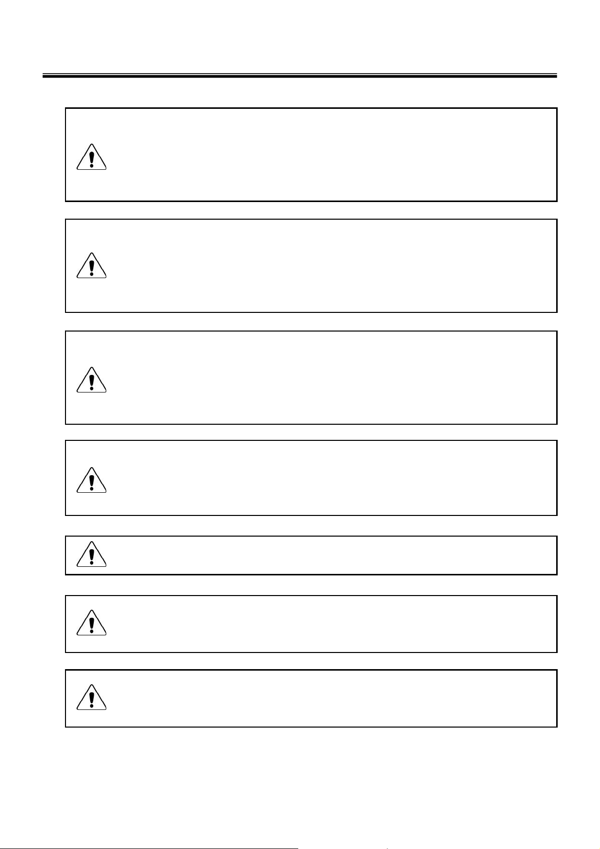
Chapter 2. Locations
■ Left View
1.Power Port
2.LAN Port
Ch2. Locations
3.Fan Louvers
4.USB Port
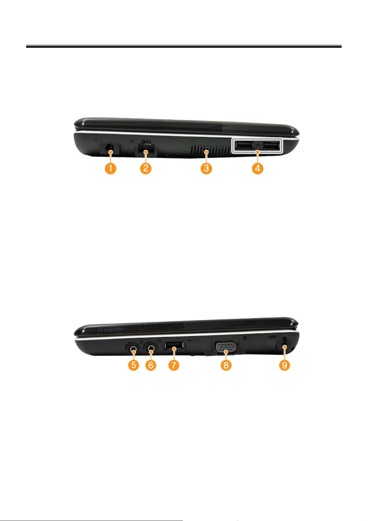
■ Right View
5.Microphone Port
6.Headphone Port
7.USB Port
8.VGA Port
9.Kensington lock
13
Page 14

■ Front View
Ch2. Locations
①
②
④
③
10.Built-in Microphone
11.Smart Cam
12.Smart ON Button
13.Power Button
14.Keyboard
15.Touch pad
16.Multi Card Slot
17.Stereo speaker
14
Page 15

Ch3. System information
Chapter 3. System information
Specification
Available Processors
• Intel® Atom™ Processor (L2 Cache Size: 512KB ) is supported.
※ The user must not replace or expand the CPU capacity arbitrarily.
The CPU capacity differs depends on model type
Main Memory
• Main memory supports both 512 MB and 1024 MB. The expansion memory slot is not supported.
※ Memory types and specifications may differ depending on the model.
Secondary Storage Devices
• 2.5" Hard Disk Drive (S-ATA)
※ The hard disk capacity and the type depend on the notebook PC model.
• External Optical Disk Drive
※ The external Optical Disk Drive is optional, and so it may not be available in some models.
.
LCD
• 10.1" WSVGA(1024 x 600) TFT Color LCD
※ Some models are equipped with the Glare‐type LCD featuring enhanced sharpness. This type of LCD appears to
glare more than other types, but it is a normal phenomenon in the Glare type.
※ The size and the resolution rate of the LCD depend on the notebook PC model.
Authentication for Anticopy Technol ogy
• U.S Patent Nos.4,631,603;4,577,216;4,819,908;4,907,093;5,315,448;and 6,516,132. Patent number of
Macrovision™.
• This product includes the technologies that are possessed by Macrovision and corresponding companies
and protected by the US Patent Law and other related laws. Use of all technologies subject to the copyrig
ts must be approved by Macrovision in advance. Otherwise, the technologies may only be used for intern
al display. Do not disassemble or remodel the product.
Bluetooth
• Broadcom BCM92070MD_REF
• Ver2.1 Bluetooth Module + EDR
※ Bluetooth is optional, and so it may not be installed in some models.
Web Camera
• 1.3 Web Camera module
• UVC(USB Video Class) driver support
※ Web Camera is optional, and so it may not be installed in some models.
15
Page 16

Chapter 3. System information
External I/O Interface
• External VGA Monitor Port: 1
• Microphone: 1
• Microphone Input Port (Mic in): 1
• Headphone Port: 1
• USB 2.0 Ports: 3
• Multi-card Slot: 1
• RJ 45 (LAN) Port: 1
• USIM Card Slot: 1
※ USIM card slot may not be provided depending on the model.
Video
• Mobile Intel Graphic Media Accelerator 950 (Dynamic Video Memory Technology)
※ The DVMT actively utilizes part of the system memory when processing large graphic data like 3D graphics.
Therefore, the size of the graphic memory is displayed as the sum of the actual graphic memory size and the
utilized amount of memory, which is decided by the size of system memory
※ Applications (graphics program, game, etc.) requiring strong graphic processing power may not work properly.
※ Specifications may differ by model type.
.
Sound
• Realtek High Definition Audio Codec(ALC262)
• Built‐in Stereo Speakers
MODEM
• Ericsson F3607gw (HSPA Modem)
※ The wireless data modem is optional, and so it may not be available in some models.
LAN
• Realtek RTL8102E/RTL8103EL Family PCI‐E Fast Ethernet NIC (10/100Mbps)
• RJ 45 Jack
※ The LAN specifications may differ dependi ng on the model.
Wireless LAN
• Ralink RT3090
※ Wireless LAN specifications may differ by model type and cannot be arbitrarily changed by the user.
Weight
• Full Installation: Approx. 1.14kg (3‐cell battery pack) / 1.27kg (6‐cell battery pack) / 1.54kg
(9‐cell battery pack)
• Battery: Approx. 180g (3 cells) / 310g (6 cells) / 470g (9 cells)
※ Weight descriptions may differ by model type.
16
Page 17

■ System Block Diagram
Chapter 3. System information
17
Page 18

Chapter 3. System information
Fn key combinations
The following table shows the function of each combination of Fn with a function key.
Function of Fn keys has nothing to do with Operating System.
Fn + F1
Fn + F2
Fn + F3
Fn + F4
Fn + F5
Fn + F6
Fn + F7
Fn + F8
Fn + F9
Fn + ▲
Fn + ▼
Customizable hot keys. (Configurable through OSD settings)
Customizable hot keys. (Configurable through OSD settings)
Magnifying hot keys.
Windows Executes the mode defined in the Power Save Mode. (Example: Standby, Hibernate)
When the user presses Fn + F5 keys, the touchpad mode toggles from Touchpad Disable, to
Touchpad Auto‐Disable (upon connection of external USB/PS2 mouse), to Touchpad Enable in
order. (Initialization takes 1 ˜ 2 seconds. It is recommended to use after the initialization.)
Turns the wireless devices (incl. Wireless LAN and Bluetooth) on and off (Bluetooth is optional, and
so it may not be installed in some models.)
Monitor toggle. If you have an external monitor connected to the computer, press Fn + F7 keys to
rotate the display mode between LCD only, Monitor only, and LCD + Monitor both in order.
When you press Fn + F8 keys, the sound mode toggles from SRS WOW HD,, to SRS TruSurround
XT, to SRS Off in order.
Mute (Sound ON / Sound OFF)
Increases LCD brightness within a nine‐grade range.
Decreases LCD brightness within a nine‐grade range.
Fn + ◀
Fn + ▶
Fn + F10
Fn + F11
Fn + F12
Fn + Num
Lk
Turns down the volume.
Turns up the volume.
System Information. System summary information will be displayed.
Fan Control feature. Switches the cooling fan mode between Normal and Silent for each pressing.
Hibernates (When OSD is installed)
When the Num Lock lamp is turned on, you can enter numbers (0~9) using the embedded
numeric keys. If you press [Fn] + [Num Lk] again, the Num Lock lamp is turned off and
you can enter text characters.
You can enter [Prt Sc Sys Rq] button.Fn + PgUp
You can enter [Pause Break] button.Fn + PgDn
You can enter [Insert] button.Fn + Delete
18
Page 19

Ch3. System information
Status indicators
The system status indicators show the status of the computer
1 . Power Lamp:
• Blinking: System Standby
• On: The system is running on the AC power or battery.
• Off: The system is turned off or in Hibernates.
2. AC Power and Battery Status Lamp
• Orange: The battery is being charged.
• Orange/Green Blinking: Charged more than 90%
• Off: The AC adapter is not connected and the battery is being discharged.
• Green: The AC adapter is connected and the battery is not in charging stage, or the battery is fully
charged.
• Green Blinking: The battery is charged less than 10%
• Red Blinking: In faulty state
• If you try to turn on the system that has entered the Hibernatesmode or been turned off after a low-battery
alarm, the system will not be turned on but the lamp will blink three times.
3. Hard Disk Drive Lamp
• The lamp is turned on when the HDD is running.
※ Do not turn off the power forcibly while the hard disk drive lamp is on. Otherwise, the data may get
impaired.
4. Num Lock lamp
• Num Lock lamp is turned on when you press [Fn] + Num Lock keys, indicating the embedded numeric
keys are available. If you press [Fn] + [Num Lk] again, the Num Lock lamp is turned off and you can
enter text charac ters.
5. Caps Lock lamp
• Caps Lock lamp is on when the it is active. When this lamp is on, you cantype uppercase letters without
holding Shift key.
19
Page 20

6 . Wireless LAN/Bluetooth lamp
• Off: Wireless LAN is not in use.
• Blinking (short interval): Wireless LAN/Bluetooth is connected and data are being transmitted.
• Blinking (every 2 ~ 3 seconds): Wireless LAN/Bluetooth is not connected but Wireless Radio is on.
• Blinking (every 3 ~ 4 seconds): An access Point is being searched for to connect Wireless LAN/Bluetooth.
• On: An access point is being searched for or Wireless LAN is connected.
※ The Wireless LAN/Bluetooth lamp may operate differently depending on model type.
※ The Wireless LAN card and the Bluetooth device are optional, and so it may not be supported in some
models.
Ch3. System information
20
Page 21

Ch3. System information
■BIOS Flash
You Can update BIOS using USB Device (FDD/USB Memory)
Because this system is not equipped with any USB Device, you have to use an external USB Device
for a BIOS update.
In order to boot up with an USB Device, please set Removable Device as the
first boot up drive in the boot menu of BIOS Setup.
· How to update flash Rom in Dos
1. Create ‘boot up’ flash update USB Device (FDD/USB Memory).
2. Copy BIOS Flash software to the flash update USB Device (FDD/USB Memory).
3. Connect the USB Device for USB Port.
4. Press F12 Key while the "LG LOGO" appears.
5. A while later, the system setup home screen appears.
6. Type in “go.bat ”. (x_xxx is Model Name & BIOS version)
7. You can see the BIOS flash process as below.
8. After flashing is completed, The co mputer turn off with automatic movement. .
21
Page 22

Ch3. System information
9. Press [F2] Key, then you can see the BIOS SETUP UTILITY screen as below.
10. It selects the :” Load Optimal Dafault” and it summons a BIOS settings at initial value.
2222
Page 23

Ch3. System information
11. It selects the “Exit & Saving Change” and it stores system a settings and the reboot
2323
Page 24

Ch3. System information
BIOS Release Process and Making Bootable CD
1. LGE(Korea) will upload BIOS Image(*.iso) to GCSC(Global Cyber Service Center:http://biz.lgservice.com)
when BIOS should be updated.
2. BIOS will include both System BIOS and EC(Embedded Controller) BIOS.
3. Service center can download BIOS file from GCSC and update BIOS according to below procedure.
4. Service center will make Bootable Image CD with Image file(*.iso) as below
a. Insert empty disc to CD-RW Drive and start Nero “StartSmart”.
b. Select “Nero Express”.
24
Page 25

Ch3. System information
c. Select “Disc Image or Saved Project”
d. Select File Format as "Image Files(*.iso)".
25
Page 26

Ch3. System information
e. Open Image File(*.iso) which is sent from LGE
f. Tab Burn then burning will be started
26
Page 27

Ch3. System information
g. Burn process completed as below, and tab “OK
27
Page 28

Ch3. System information
BIOS/EC Flash Process
1. Insert Bootable CD in PC, and Turn it on, then PC will boot by DOS mode as below
(If the EC is not correct or old version, then automatically update EC first and reboot again)
2. Select Boot mode, then press “Enter” Key.
3. Type in LOGO SETTING at the “WIP ID :” then press Enter key (You must use Capital Letter)
28
Page 29

Ch3. System information
4. Type in Mode Name at the “WIP ID :” then press Enter key (You must use Capital Letter)
(You can see the Model Name in ID Label at the bottom Case of PC: “M/N: LMXX-XXXX”)
5. Type in Serial No at the “WIP ID :” then press Enter key (You must use Capital Letter)
(You can see the Serial No in ID Label at the bottom Case of PC: “S/N: 412KIXXXXXXXX”(13digits))
6. You can see the BIOS flash process as below
29
Page 30

Ch3. System information
5. After flashing is completed, you can see the “PASS” on your screen, and reboot your PC
30
Page 31

Ch3. System information
BIOS Setup
BIOS (Basic Input and Output System) Setup saves the system confi g urat io n in CMOS RAM , and
check the configurations during startup. Use the BIOS Setup Utility to change and save the system
environment, hardware configurations, power saving mode, etc.
· Open the BIOS Setup Utility in the following situations :
1. to change the BIOS setup
2. to replace the backup battery
3. system configuration error occurs
4. to change the boot order
5. to set/change a password
Press the power button.
When the LG logo appears on the screen, press and enter the BIOS Setup Utility.
31
Page 32

Ch3. System information
Using the keys
The keys used in the BIOS Setup Utility and their functions are described at the bottom.
· , + : General Help
Display the descriptions of the keys used in the setup utility.
· , : Select Item
Navigate and select items in the setup utility. The selected item becomes highlighted.
· , : Select Menu
Move to another menu.
· / , : Change Values
Change the value of a selected item.
· : Load Default Configuration
Display Setup Confirmation window. Press Enter to load default configuration.
· : Select Sub-Menu
Some items have sub-menus. Display the sub-menu for a selected item.
· : Save and Exit
Display Setup Confirmation window. Press Enter to save and exit.
·: Exit
In a sub-menu, press Esc to move to the previous window. In Main menu, click Esc to move to Exit menu.
32
Page 33

Main menu
Ch3. System information
· System Time
Current time. To change the value, press <+> or <−> key.
· System Date
Current date. To change the value, press <+> or <−> key.
· Hard Drive
To change the settings of the connected drive, click <Enter> after selecting this option.
.
3333
Page 34

Advanced menu
Ch3. System information
· USB BIOS Legacy Support
This enables to use the USB devices in the MS-DOS environment.
· HDC Configure as
This configures the compatibility settings for the SATA controller.
VT Support
·
Set whether or not to support the Intel virtualization technology.
· AC Mode Fan always on
Select any of Normal, Silent, and Cool for the operating speed of CPU cooling fan (for AC power).
DC Mode Fan always on
·
Select any of Normal, Silent, and Cool for the operating speed of CPU cooling fan (for DC power).
Mute button option
·
Set whether or not to support the Mute function (Fn + F9) during the system startup.
DeepC4
·
In order to reduce electricity cache L2 disable, CPU to idle conditions and in order to enter.
3434
Page 35

Security menu
Ch3. System information
· TPM Operation
Trusted with Platform Module abbreviations keyboard input or the hazard which removes a
different security risk factor they are SW and HW security modules which devise.
· Supervisor Password
The password setting prevents not allowed users from using the notebook computer. The password is not
set when starting the system for the first time. When the system is turned on, any other user cannot
change the BIOS settings without entering the specified password.
· User Password
Set User Password is for setting the password lower than the one set in Set Supervisor Password. Set
User Password is active only when the supervisor password is set.
· Set Supervisor Password
Set Supervisor Password.
· Set User Password
Set User Password.
· Set All Hdd Password
Set the HDD password.
3535
Page 36

Boot menu
Ch3. System information
· Quick Boot
Set whether or not to use Quiet Boot.
· PXE Boot to LAN
Set whether or not to use the HDD password.
· Boot Menu
Boot poem F12 pressing, boot device Selection the boot device.
· Boot Device Priority
Select the desired device drive by using the arrow buttons and change its booting sequence
by using the [+] or [-] key.
3636
Page 37

Info menu
Ch3. System information
· BIOS Version
This shows the Version of BIOS.
· KBC Version
This shows the Version of KBD firm ware.
· Serial Number
This shows the serial number of the product.
· CPU Type
This shows the type of the CPU installed in the system.
· Cache RAM
This shows the size of L2 Cache for the CPU.
· Total Memory
This is for display only. This shows size of system memory.
3737
Page 38

Exit menu
Ch3. System information
· Exit & Save Change
Save the changes you have made and exit the utility.
· Exit & Discard Chang es
Exit the utility without saving the changes you have made.
· Load Optimal Defaults
This changes the parameters in the Setup menu to the factory default settings. When it is selected or [F9]
key is pressed, the confirmation message appears. Click [Yes] to change the settings.
· Load Custom Defaults
This returns the user-defined settings for the parameters in the Setup menu.
· Save Custom Defaults
This saves the desired values for each parameter in the Setup menu.
· Discard Changes
This returns to the factory default settings for each parameter in the Setup menu.
3838
Page 39

Ch3. System information
■ Backup and Restore Security Platform Data
Security Platform Backup includes all data required in case of emergency. After a hardware or storage
media failure or a Trusted Plat form Module failure, Security Platform Restoration reesta blish es access to
Security Platform Features for all users.
In addition you can backup and restore your Personal Secure Drive data. Data from other applications
using the Security Platform Solution (e.g. Secure e-mail) is not included in Security Platform backup.
■ Backup scope
Security Platform backup comprises the following data:
Security Platform Credentials and Settings
Backup Contents
Purpose
Archives
Emergency Recovery
Backup Contents
Purpose
A copy of the user-specific credentials and settings which are stored on the
Security Platform.
Restoration of user-specific crede ntials and settings after a hardware or
storage media failure.
Otherwise users could not access Security Platform Features anymore
and user data would be lost.
•
Automatically written Backup Archive ("System Backup Archive",
e.g. file
Security Platform Administrator. Contains credentials and settings of all
Security Platform Users (for one or multiple Security Platform
computers). Also contains computer identification and user
identification, which are used to match computers and users during the
restoration process.
•
Manually written Backup Archive (e.g.
Created by Security Platform User. Contains credentials and settings of
one Security Platform User (for one Security Platform computer). Also
contains computer identification and user i denti fication, which are used
to match computer and user during the restoration proces s.
All Security Platform Basic User Keys, encrypted specifically for Emergency
Recovery.
Re-encryption of all Basic User Keys after a Trusted Platform Module failure.
In this case a new Security Platform has to be set up and a new owner
key is created. Emergency Recovery allows the re-encryption of Basic
User Keys from the old owner key to the new one.
Otherwise users could not access Security Platform Features anymore
and user data would be lost.
SPSystemBackup.xml
and folder
SPSystemBackup
SPBackupArchive.xml
): Set up by
):
Archives
•
Emergency Recovery data is included in automatically writ ten
Backup Archives.
•
Emergency Recovery Token (e.g.
Security Platform Administrator. Protected with a dedicated password.
Is required for a restoration of Emergency Recovery data.
SPEmRecToken.xml
): Created by
39
Page 40

Personal Secure Drive
Ch3. System information
A copy of the PSD encrypted data and configuration settings.Backup Contents
Purpose
Archives
Restoration of PSD encrypted data and configuration settings after a
hardware or storage media failure.
Otherwise users could not decrypt their PSD data anymore.
Notes:
•
In contrast to the PSD Backup, standard hard disk backup tools
produce unencrypted backups.
•
Lost PSD credentials can only be restored via Personal Secure Drive
Recovery.
•
PSD configuration settings are included in both automatically
written Backup Archives and manually written Backup Archives.
•
PSD backup file (e.g.
image file may be created during a Security Platform User's manual
backup.
SpPSDBackup.fsb
■ Restoration Cases
Depending on the type of emergency there are different restoration cases
Affected Restoration ScopeRestoration Case
Broken hard disk or lost data
Security Platform Credentials and Settings, Personal
Secure Drive
Emergency RecoveryNew Trusted Platform Module
): A backup copy of the PSD
New Security Platform to be initialized
Emergency Recovery, Security Platform Credentials
and Settings, Personal Secure Drive
40
Page 41

Ch3. System information
■ How to Backup and Restore
("System Backup")
Software Component to useHow to configure automatic backups
Administrative Task: Configure automatic
backups for all users (including Security
Platform Credentials and Settings,
Emergency Recovery and PSD configu ration
settings).
current user.
certain users.
User Task: Run restoration manually for
current user. If restoration has been
prepared for current user, then complete the
restoration.
If a manually written Backup Archive is
available and no Emergency Recovery data
needs to be restored, then a user can
perform restoration without preparation by
an administrator.
■ Backup
If Security Platform is not yet initialized:
Initialization Wizard
If Security Platform is already initialized: Settings
Tool -Backup -Configure...
Software Component to useHow to backup ("Manual Backup")
Settings Tool - Backup - Backup...User Task: Run backup manually for the
Software Component to useHow to restore
Settings Tool - Backup - Restore...Administrative Task: Prepare restoration for
With this page you can configure automatic Security Platform backups.
The following table gives hints on how to use this wizard page.
ExplanationWizard Page Element
Backup location:
Browse...
Schedule...
Security Platform credentials and settings will be regularly saved to a
Backup Archive.
Type in path and file name or browse for it. An automatically written
Backup Archive consisting of an XML file and a folder with the same name
will be created, e.g. file
Please use the extension *.xml.
A scheduled backup will be created.
Click here to view and modify the backup scheduling.
Please note that automatic backups are only executed if your PC is not
shut down at the scheduled time.
Please note that the user account chosen for the scheduled backup must
be member of the group "Administrators" or "Backup Operators".
SPSystemBackup.xml
and folder
SPSystemBackup
.
41
Page 42

Ch3. System information
■ Infineon Platform Security Backup
With this page you can backup and restore Security Platform credentials, Security Platform settings and
Personal Secure Drives.
If Enhanced Authentication is enabled, you can also create backups of your authentication device.
Availability of page: This page is only available on an initialized Security Platform, if one of
the following conditions is fulfilled:
•
The current user has administrative rights.
•
The current user is an initialized Security Platform User, and the policy Allow User Enrollment
is enabled.
Buttons:
•
Buttons for administrative tasks are disabled for users without administrative rights.
•
Buttons are disabled, if corresponding functions are not available in a certain Security Platform
state.
The following table describes all backup and restore functions.
Explanation
Click here to set up automatic Security Platform backups.
Infineon Security Platform Initialization Wizard will be started.
This feature is only available, if the current user account has administrative rights.
Click here to start a manual backup of your Security Platform Settings and credentials. If you have
configured Personal Secure Drive (PSD), you can ba ckup your PSD too.
The Infineon Security Platform Backup Wizard will be started.
This button is disabled, if the Infineon Security Platform is disabled, not yet set up or the user is not
set up.
Click here to start a manual restore of archived Security Platform Settings and credentials. If you
have a backup of your Personal Secure Drive (PSD), you can restore your PSD too.
The restore part of the Infineon Security Platform Backup Wizard will be started.
This button is disabled, if the Infineon Security Platform is disabled or not yet set up.
Click here to create a backup authentication device.
This feature is only available, if Enhanced Authentication is enabled.
42
Page 43

Ch4. Symptom-to-part index
Chapter 4. Symptom-to-part index
The symptom-to-part index in this section lists symptoms and errors and their possible causes.
The most likely cause is listed first.
Note
If replacing a part (FRU) does not solve the problem, put the original part back in the computer.
Do not replace a non-defective FRU.
Power system checkout
· To verify a symptom, do the followin g :
1. Power off the computer.
2. Remove the battery pack.
3. Connect the AC adapter.
4. Check that power is supplied when you power on the computer.
5. Power off the computer.
6. Disconnect the AC adapter and install the charged battery pack.
7. Check that the battery pack supplies power when you power on the computer.
· If you suspect a power problem, see the appropriate one of the following power supply checkouts :
1. Checking the AC adapter
2. Checking the operational charging
3. Checking the battery pack
4. Checking the backup battery
· Checking the AC adapter
If the power-on indicator does not turn on, check the power cord of the AC adapter for correct continuity
and installation.
If the computer does not charge during operation, go to “Checking operational charging.”
43
Page 44

Ch4. Symptom-to-part index
To check the AC adapter, do the following :
1. Unplug the AC adapter cable from the computer.
2. Measure the output voltage at the plug of the
AC adapter cable. See the following figure :
3. If the voltage is not correct, remove the power code
2
1
form AC adapter.
4. 10 seconds later, connect the power code, then measure the output voltage.
5. If the voltage is not correct, change the AC adapter.
Voltage (V dc)Pin
+18.05 ~ +19.951
Ground2
44
Page 45

Ch4. Symptom-to-part index
· If the voltage is not correct, replace the AC adapter.
· If the voltage is acceptable, do the following :
1. Replace the system board.
2. If the problem persists, check the AC adapter whether it is correct product or not.
Note
Noise from the AC adapter does not always indicate a defect.
· Checking operational charging
1. To check whether the battery charges properly during operation, use a discharged battery pack or a
battery pack that has less than 50% of the total power remaining when installed in the computer.
Perform operational charging. If the battery status indicator or icon does not turn on, remove the battery
does not turn on, replace the battery pack.
2. If the charge indicator still does not turn on, replace the system board.
Then reinstall the battery pack.
Note
Do not charge battery pack, when its temperature is below 0 or above 75 .
· Checking the battery pack
1. Open the Power Meter window by clicking Start Control Panel Power Options and then;
check the total power remains. Battery charging does not start until the power Meter shows that less
than 95% of the total power remains; under this condition the battery pack can charge to 100% of its
capacity. This protects the battery pack from being overcharged or from having a shortened life.
2. To check the status of your batter, move your cursor to the Power Meter icon in the icon tray of the
Windows taskbar and wait for a moment (but do not click), and the percentage of battery power
remaining is displayed. To get detailed information about the battery, double-click the Power Meter icon.
Note
If the battery pack becomes hot, it may not be able to charge. Remove it from the computer and
Leave it at room temperature for a while. After it cools down, reinstall and recharge it.
45
Page 46

Ch4. Symptom-to-part index
· The Characteristics of the battery pack
1. Self-discharge
The battery gradually loses its power over time without ever being used.
2. Periodic full discharge / charge
Frequent recharge of the battery pack can reduce the capacity of the battery pack. When this happens,
you can perform the full discharge / charge to improve the capacity. You should perform periodic full
discharge /charge once every 30~60 days.
You should always use the battery until its power is low; then fully charge the battery.
3. Trickle charge
If the temperature of the battery pack drops below 10 , the trickle charging begins.
The trickle charging may take 32 hours for the battery pack to be fully charged.
46
Page 47

Ch4. Symptom-to-part index
· To check the battery pack, do the following :
1. Power off the computer.
2. Remove the battery pack and measure the voltage between battery terminals 1(-) and 5(+).
See the following figure :
Voltage (V dc)Terminal
Ground(-)1
5(+) 4 3 2 1(-)
3. If the voltage is still less than +11.1 V DC after recharging, replace the battery.
4. If the voltage is more than +11.1 V DC, measure the resistance between battery terminals 1 and 2.
The resistance must be 2 to 4 (typically 3 ).
5. If the resistance is not correct, replace the battery pack. If the resistance is correct, replace the system
board.
Note
Charging will take at least 3 hours.
Note
Battery is an expendable supplier, so its capacity and used time can be reduced by using the computer.
5
+0V ~ +12.6V
(6 cell)
47
Page 48

Numeric error codes
Ch4. Symptom-to-part index
FRU or action, in sequenceSymptom / Error
0200
Fixed disk failure
(The hard disk is not working)
0210
Stuck Key error
0211
Keyboard error
Keyboard Controller Failed
Monitor type error - Monitor type does not
match the one specified in CMOS.
1.Reset the hard-disk drive.
2.Load Setup Defaults in BIOS Setup Utility.
3.Hard-disk drive.
4.System board.
1.Check the keyboard if it is pressed.
2.Replace the keyboard.
Run interactive tests of the keyboard and the auxiliary
input device.
System board.0212
Load Setup Defaults in BIOS Setup Utility.0220
0230
System RAM error - System RAM Failed at
offset.
Shadow RAM error - Shadow RAM failed at
offset
0232
Extended RAM error - Extended RAM Failed
at address line
0250
System battery error – System battery is dead
1.DIMM
2.System board
System board0231
1. DIMM
2. System board
Replace the backup battery and run BIOS Setup
Utility
to reset the time and date.
48
Page 49

Ch4. Symptom-to-part index
FRU or action, in sequenceSymptom / Error
0251
System CMOS checksum bad
– System CMOS checksum is not correct.
– Default configuration used.
Password checksum bad – The password is
cleared.
0260
System timer error
Check date and time settings – Date and time
error.
0280
Previous boot incomplete
- Default configuration used
from EISA CMOS
Diskette drive A error
Replace the backup battery and run BIOS Setup
Utility
to reset the time and date.
Reset the password by running BIOS Setup Utility.0252
1. Replace the backup battery and run BIOS
Setup Utility to reset the time and date.
2. System board.
Run BIOS Setup Utility to reset the time and date.0271
1. Load “Setup Default” in BIOS Setup Utility.
2. DIMM.
3. System board.
Load Setup Defaults in BIOS Setup Utility.0281: Memory Size found by POST differed
Set up the diskette type in BIOS Setup Utility.02B0
Diskette drive B error
02B2
Incorrect drive A type – Floppy diskette drive
error
02B3
Incorrect Drive B type
02D0
System cache error – Cache disabled
(RAM cache failed and BIOS disabled)
02F4
EISA CMOS not writable
02F5
DMA test failed
02F6
Software NMI failed
Set up the diskette type in BIOS Setup Utility.02B1
1. Floppy diskette drive.
2. External FDD cable.
3. I/O card.
1. Floppy diskette drive.
2. External FDD cable.
3. I/O card.
1. Load “Setup Default” in BIOS Setup Utility.
2. System board.
1. Load “Setup Default” in BIOS Setup Utility.
2. Replace the backup battery.
3. System board.
1. DIMM
2. System board
1. DIMM
2. System board
49
Page 50

Ch4. Symptom-to-part index
FRU or action, in sequenceSymptom / Error
02F7
Fail – Safe timer NMI failed
0611
IDE configuration changed
0612
IDE configuration error
0613
Com A configuration changed
0614
Com A configuration error
0615
Com B configuration changed
1. DIMM
2. System board
1. Load Setup Defaults in BIOS Setup Utility.
2. System board.
1. Load Setup Defaults in BIOS Setup Utility.
2. System board.
1. Load Setup Defaults in BIOS Setup Utility.
2. System board.
1. Load Setup Defaults in BIOS Setup Utility.
2. System board.
1. Load Setup Defaults in BIOS Setup Utility.
2. System board.
0616
Com B configuration error
0617
Floppy configuration changed
0618
Floppy configuration error
0619
Parallel port configuration changed
061A
Parallel port configuration error
1. Load Setup Defaults in BIOS Setup Utility.
2. System board.
1. Load Setup Defaults in BIOS Setup Utility.
2. System board.
1. Load Setup Defaults in BIOS Setup Utility.
2. System board.
1. Load Setup Defaults in BIOS Setup Utility.
2. System board.
1. Load Setup Defaults in BIOS Setup Utility.
2. System board.
50
Page 51

Error message
Ch4. Symptom-to-part index
FRU or action, in sequenceSymptom / Error
Device address conflict.
Allocation error for device.
Failing bits: nnnn.
Invalid System Configuration Data.
I/O Device IRQ Conflict.
1. Load Setup Defaults in BIOS Setup Utility.
2. Backup battery.
3. System board.
1. Load Setup Defaults in BIOS Setup Utility.
2. Backup battery.
3. System board.
1. DIMM.
2. System board.
1. DIMM.
2. System board.
1. Load Setup Defaults in BIOS Setup Utility.
2. Backup battery.
3. System board.
Operating System not found.
Hibernation error.
1. Check that the operating system has no failure and
is installed correctly.
2. Enter BIOS Setup Utility and see whether the hard
-disk drive and the diskette drive are p rop erly
identified.
3. Reset the hard-disk drive.
4. Reinstall the operating syst em.
5. Diskette drive.
6. Hard-disk drive.
7. System board.
1. Restore the system configuration to what it was
before the computer entered hibernation mode.
2. If memory size has been changed, re-create the
hibernation file.
Fan.FAN error.
51
System board.Thermal sensing error.
Page 52

Ch4. Symptom-to-part index
LCD-related symptoms
Note
Before removing or disassembling LCD, power off the computer, unplug all power cords from electrical
outlets, remove the battery pack also.
FRU or action, in sequenceSymptom / Error
Check out Battery Miser.LCD screen becomes dark suddenly.
Nothing displayed on LCD screen.
LCD backlight not working.
LCD too dark.
LCD brightness cannot be adjusted.
LCD color cannot be adjusted.
LCD screen abnormal.
Characters missing pixels.
LCD screen unreadable.
Wrong color displayed.
1. Check out Battery Miser.
2. Choose Never in the Turn off Monitor item on
Power Options Properties.
3. Check the power save mode switch if it is pressed
by something.
4. Check the System is in standby or hibernation
mode.
1. Reconnect inverter to the board connector.
2. Replace inverter.
3. LCD Assembly.
4. System board.
1. Reset all LCD connectors.
2. Replace LCD cable.
3. LCD Assembly.
4. System board.
on LCD
Power-on indicator on, and a blank\LCD
during POST.
LCD Assembly.Horizontal or vertical lines displayed
LCD Assembly.
System board.
52
Page 53

Ch4. Symptom-to-part index
Indeterminate problems
· You are here because the diagnostic tests did not identify which adapter or device failed, wrong devices
are installed, a short circuit is suspected, or the system is inoperative.
Follow these procedures to isolate the failing FRU (do not isolate FRUs that have no defects).
· Verify that all attached devices are supported by the computer.
· Verify that the power supply being used at the time of the failure is operating correctly.
1. Power off the computer
2. Visually check each FRU for damage. Replace any damaged FRU.
3. Remove or disconnected all of the foll owi ng d evice s :
a. Non-LG devices.
b. Printer, mouse, and other external devices.
c. Battery pack.
d. PC cards.
e. ODD (CD-ROM, Combo) drive or FDD drive in the Bay.
f. Hard-disk drive.
Note
Use the other memory card because it needs when operating computer.
4. Power on the computer.
5. Determine whether the problem has changed.
6. If the problem does not recur, reconnect the removed devices one at a time until you find the failing FRU.
7. If the problem remains, replace the following FRUs one at a time.
(do not replace a non-defective FRU)
a. LCD Assembly (Check external monitor whether the same problem recurs or not).
b. Keyboard.
c. Keydeck (TouchPad and Scroll Button Assembly).
d. System board.
53
Page 54

Ch5. Removing and replacing a part
Chapter 5. Removing and replacing a part (FRU)
Danger
Before removing any FRU, power off the computer, unplug all power cords from electrical
outlets, remove the battery pack, and then disconnect any interconnecting cables.
Caution
Before the computer is powered on after FRU replacement, make sure that all screws, springs,
and other small parts are in place and are not loose inside the computer. Verify metal flakes can
cause electrical short circuits.
Note
-As for the screw, every Torque 3 0.2Kgfcm(0.196Nm)
-For further information on Removin g an d Re pl aci n g a Part(FRU), ref er to Ex pl ore view.
54
Page 55

Ch5. Removing and replacing a part
■ 1010 Battery Pack
1. Push the battery latch in the direction shown below; then slide the battery pack out of the slot.
2. Remove the Battery Pack.
5555
Page 56

Ch5. Removing and replacing a part
■ 1020 Hinge / Keyboard
※ Remove the following parts in order before replacing this part
a. Battery Pack(1010)
1. Remove the 5 screw.
No. FRU No. Specification Qty
1
2
2. Remove the Hinge.
FAB30208501
FAB30248901 (M2.5*6.5) black
(M2.0*3.0) White
3EA
2EA
5656
Page 57

Ch5. Removing and replacing a part
3. It uses JIG and it removes the Hooks.
4. Remove the Keyboard Connector Cable.
5757
Page 58

5. Remove the Keyboard.
Ch5. Removing and replacing a part
5858
Page 59

Ch5. Removing and replacing a part
■ 1030 Bottom Case
※ Remove the following parts in order before replacing this part
a. Battery Pack(1010), b. Hinge / Keyboard(1020)
1. Remove the 8 screw.
No. FRU No. Specification Qty
1
2. Remove the 1 Cable and 2 Screw.
FAB30487201 (M2.0*5.0) black
8EA
Cable
No. FRU No. Specification Qty
1
FAB30487201 (M2.0*5.0) black
2EA
5959
Page 60

Ch5. Removing and replacing a part
3. Uses JIG and from the left side removes Bottom Case.
6060
Page 61

Ch5. Removing and replacing a part
6161
Page 62

Ch5. Removing and replacing a part
■ 1040 LCD Assembly
※ Remove the following parts in order before replacing this part
a. Battery Pack(1010), b. Hinge / Keyboard(1020) , c. Bottom Case(1030)
1. Remove the 5 cable.
Cable
2. Remove the 4 screw.
Antenna
No. FRU No. Specification Qty
1
FAB30487201 (M2.0*5.0) black
4EA
6262
Page 63

Ch5. Removing and replacing a part
3. Remove the LCD Assembly.
6363
Page 64

Ch5. Removing and replacing a part
■ 1050 HDD
※ Remove the following parts in order before replacing this part
a. Battery Pack(1010), b. Hinge / Keyboard(1020) , c. Bottom Case(1030)
1. Remove the 3 screw.
No. FRU No. Specification Qty
1
2. Remove the HDD
FAB30208501 ( M2.0*3.0) White
3EA
6464
Page 65

3. Remove the 4 screw.
Ch5. Removing and replacing a part
4. Remove the HDD Shield.
QtySpecificationFRU No.No.
4EA1
6565
Page 66

Ch5. Removing and replacing a part
■ 1060 Mainboard
※ Remove the following parts in order before replacing this part
a. Battery Pack(1010) b. Hinge / Keyboard(1020) c. Bottom Case(1030) d.HDD(1050)
1. Remove the 2 cable.
Cable
2. Remove the 2 screw.
QtySpecificationFRU No.No.
1
(M2.0*3.0) WhiteFAB30208501
2EA
6666
Page 67

Ch5. Removing and replacing a part
3. Remove the Mainboard / USB(R) Sub Board.
6767
Page 68

Ch5. Removing and replacing a part
■ 1070 Bluetooth Module
※ Remove the following parts in order before replacing this part
a. Battery Pack(1010) b. Hinge / Keyboard(1020) c. Bottom Case(1030) d.HDD(1050)
e. Mainboard(1060)
1. Remove the bluetooth.
2. Remove the bluetooth module.
6868
Page 69

Ch5. Removing and replacing a part
■ 1080 Speaker
※ Remove the following parts in order before replacing this part
a. Battery Pack(1010) b. Hinge / Keyboard(1020) c. Bottom Case(1030) d.HDD(1050)
e. Mainboard(1060)
1. Remove the 2 screw.
1
2. Remove the Speaker.
QtySpecificationFRU No.No.
(M2.0*3.0) WhiteFAB30208501
2EA
6969
Page 70

Ch5. Removing and replacing a part
■ 1090 CPU Fan Assembly
※ Remove the following parts in order before replacing this part
a. Battery Pack(1010) b. Hinge / Keyboard(1020) c. Bottom Case(1030)
1. Remove the 1 Cable and 4 Screw.
Cable
No. FRU No. Specification Qty
1
2. Remove the CPU Fan Assembly.
FAB30208501 (M2.0*3.0) White
4EA
7070
Page 71

Ch5. Removing and replacing a part
■ 1100 HSDPA Module
※ Remove the following parts in order before replacing this part
a. Battery Pack(1010) b. Hinge / Keyboard(1020) c. Bottom Case(1030)
1. Remove the 1 screw.
No. FRU No. Specification Qty
1
2. Remove the HSDPA Module.
(M2.0*3.0)WhiteFAB30208501
1EA
7171
Page 72

Ch5. Removing and replacing a part
■ 1110 WLAN Module
※ Remove the following parts in order before replacing this part
a. Battery Pack(1010) b. Hinge / Keyboard(1020) c. Bottom Case(1030)
1. Remove the 1 screw.
No. FRU No. Specification Qty
1
2. Remove the WLAN Module.
(M2.0*3.0) WhiteFAB30208501
1EA
7272
Page 73

Ch5. Removing and replacing a part
■ 1120 DIMM
※ Remove the following parts in order before replacing this part
a. Battery Pack(1010) b. Hinge / Keyboard(1020) c. Bottom Case(1030)
1. Remove the Hook.
2. Remove the DIMM.
Hook
Hook
7373
Page 74

Ch5. Removing and replacing a part
■ 1130 LCD Front Case
※ Remove the following parts in order before replacing this part
a. Battery Pack(1010), b. Keyboard(1020) , c. Bottom Case(1030), d. F. LCD Assembly (1040)
1. Remove the 4 Rubber and 2 screw.
No. FRU No. Specification Qty
1 FAB30493201 (M2.0*5.0) white 4EA
2. Uses JIG and from the removes LCD Front Case.
7474
Page 75

Ch5. Removing and replacing a part
■ 1140 LCD Panel
※ Remove the following parts in order before replacing this part
a. Battery Pack(1010), b. Keyboard(1020) , c. Bottom Case(1030), d. LCD Assembly (1040),
e. LCD Front Case(1130)
1. Remove the 1 cable andd and 2 screw.
Cable
No. FRU No. Specification Qty
1 FAB30493201
2. Remove the 4 screw.
(M2.0*5.0) white
2EA
No. FRU No. Specification Qty
1
FAB30487201 (M2.0*5.0) white
4EA
7575
Page 76

3. Remove the LCD Panel.
Ch5. Removing and replacing a part
7676
Page 77

Ch5. Removing and replacing a part
■ 1150 LCD Cable
※ Remove the following parts in order before replacing this part
a. Battery Pack(1010), b. Keyboard(1020) , c. Bottom Case(1030), d. LCD Assembly (1040),
e. LCD Front Case(1130), f. LCD Panel(1140)
1. Remove the LCD Cable.
Cable
77
77
Page 78

Ch5. Removing and replacing a part
■ 1160 Web Cam Module
※ Remove the following parts in order before replacing this part
a. Battery Pack(1010), b. Keyboard(1020) , c. Bottom Case(1030), d. LCD Assembly (1040),
e. LCD Front Case(1130), f. LCD Panel(1140)
1. Remove the Web Cam Module.
7878
Page 79

Ch6. P
a
y
gy
MAZ61973301
NHDD03
E
B
B
B
p
HDD BKT RIGHT UL1(FBUL1003,REV3A)
rt lists
Chapter 6. Part lists
LG P/NLoc. No.Categor
MAIN B/D
Cover
HDD
Keyboard
MiniCard
ACQ74811101NCVR01
ACQ74811102NCVR01
EAZ60666001NHDD01
EAZ60666901NHDD01
EAZ50165401NHDD01
EAZ60665701NHDD01
EAZ40236713NHDD01
MAZ61973302NHDD02
AEW72909201NKBD01
AEW72909202NKBD01
AEW72909203NKBD01
AEW72909204NKBD01
AEW72909205NKBD01
AEW72909206NKBD01
AEW72909207NKBD01
AEW72909208NKBD01
AEW72909209NKBD01
AEW72909210NKBD01
AEW72909211NKBD01
AEW72909212NKBD01
AEW72909213NKBD01
AEW72909214NKBD01
AEW72909215NKBD01
AEW72909216NKBD01
EAT60670601NMINI01
EAD60864201NMINI02
EAD60864202NMINI02
EAD60864203NMINI02
EAT60666303NMINI03
EBM60659701NMINI04
EBM60659401NMINI04
REV.07
RemarkDescription
UL1 EBR63943001NMLB01
M/B N270(1.6G/945GMS/ICH7M) FSB533Mhz
UL1 M/B EBR63943002NMLB01
N280(1.66G/945GMS/ICH7M/WO 3G) FSB667Mhz
Memory_ DOOR Cover _ White
Memory_DOOR Cover _ Black
HDD(160G)_HITACHI
HDD(160G)_Fujitsu
HDD(160G)_WESTERN DIGITAL
HDD(160G)_SEAGATE
HDD(250G)_SEAGATE
HDD BKT LEFT UL1(FBUL1004,REV3A)
Korean type
English type
UK type
Nordic type
German type
Brazilian type
Russian
Spanish
Turkish
Portuguese
Greek
canadian french
French
Hebrew
Arabic
Italian
BLU
TOOTH 2.1+EDR USB MODUL(QBT410UB-01)
CA
LE ASSY UL1 BLUETOOTH(6/6P,REV1A)5V
CA
LE ASSY UL1 BLUETOOTH(6/6P,2A)5V-MEC Alternative
CA
LE ASSY UL1 BLUETOOTH(6/6P,3A)5V-XME
3G CARD_F3607GW
WLAN 802.11 B/G/N Q802XKN3
WLAN 802.11B/G/N 9WEM307QCE02Q
10/30
add(09')
12/22
add(09')
77
99
Page 80

Ch6. P
a
LG P/N
Loc. No
Category
F
EAC60674706
NBATT01
F
Webcam
EBP60718904
NWEBC01
Module
AFP72922401
NBOTM01
Remark
Description
델에
LGC first 2200 mAh LGC
k
델에
붙여
3G
1.3M CMOS BISON Electronics Inc_(for 3G SKU)
Bottom case Assy_White
rt lists
Chapter 6. Part lists
.
Memory
Battery
Webcam
Dummy
Socket
Thermal
Keyboard
Deck
Bottom
EAN56411504NMRY01
EAN48754301NMRY01
EAC60674704NBATT01
EAC60674705NBATT01
EAC60674702NBATT01
EAC60674709NBATT01
MCK62677202NDOS01
MCK62677201NDOS01
EAL60660001NFAN01
EAL60660101NFAN01
MAZ61986201NFAN02
MAZ61986202NFAN02
EBR63943601NSUB01SUB B/D
ABQ72952601NKDECK01
AFP72922402NBOTM01
REV.07
RAM(1GB)DDR2_A-DATA
RAM(1GB)DDR2_Hynix
LGC sole 2200 mAh LGC cell_3 cell white
LGC sole 2200 mAh LGC cell_3 cell black
LGC first 2200 mAh LGC cell_6 cell white
cell_6 cell blac
FoxEAC60674701NBATT01
link second 2250 mAh Sanyo cell_6 cell white
FoxEAC60674707NBATT01
link second 2250 mAh Sanyo cell_6 cell black
oxlink sole 2600 mAh LGC cell_9 cell white
FEAC60674708NBATT01
oxlink sole 2600 mAh LGC cell_9 cell black
3G / Non
3G 모
는
Webcam 1EBP60718901NWEBC01
.3M CMOS BISON Electronics Inc_(for non 3G SKU)
DUMMY CARD _BLACK
DUMMY CARD_WHITE
FAN moduel _ Fan_DIS
AN DIS ASSY FCN, 5V(51.3*47*7.9)0F966
HEAT SINK FCN
HEAT SINK KPT
Audio / USB Sub board
Keyboard Deck Assy
(with touch pad & touch cable & speaker)
Bottom case Assy_Black
Webcam
P/N EBP6
0718901 ,
EBP60718
904 대치
로가능
3G 모델에
는 Ali-foil을
Ant. 성능
개선한 것
Alternative
Alternative
LCD
MCK62674301NLCD01
MCK62674302NLCD01
ABQ72954802NLCD02
ABQ72954801NLCD02
ABQ72953503NLCD03
ABQ72953506NLCD03
ABQ72953509NLCD03
ABQ72953501NLCD03
88
Hinge cap black normal paint
rear case assy (black_Xnote)
rear case assy (black_LG_HSPA)
rear case assy (white_Xnote)
00
Hinge cap
10/7
add(09')
Front case assy _ Black
Front Case assy _ White
rear case assy (black_LG)
Page 81

Ch6. P
a
y
gy
ABQ72953511
NLCD03
D
D
D
D
ABQ72953514
NLCD03
H
H
H
H
H
H
H
H
ABQ72952401
NLCD07
A
EU (Turkey,S
W
p
dd(09')
rear case assy(Red
LG) ASSY
rear case assy (black normal CI_LG)
INGE RIGHT SNR UL1(FBUL1010,REV3A)
Finland,Denmark,Norway,Germany,Spain) type
rt lists
Chapter 6. Part lists
LG P/NLoc. No.Categor
ABQ72953504NLCD03
ABQ72953507NLCD03
ABQ72953505NLCD03
ABQ72953502NLCD03
ABQ72953508NLCD03
ABQ72953512NLCD03
ABQ72953510NLCD03
ABQ72953513NLCD03
EAJ60741701NLCD04
LCD
EAD60863601NLCD05
EAD60863602NLCD05
EAD60863603NLCD05
EAD60863604NLCD05
ABQ72952202NLCD06
ABQ72952302NLCD06
ABQ72952402NLCD06
ABQ72954902NLCD06
ABQ72952201NLCD07
ABQ72952301NLCD07
rear case assy (white_LG)
rear case assy (white_LG_HSPA)
rear case assy (pink_LG)
rear case assy (pink_Xnote)
rear case assy (pink_LG_HSPA)
-
rear case assy(Red-LG-HSPA)
rear case assy(Red-Xnote)
rear case assy(Black_CI-Xnote)
LCD 10.1" WSVGA 1024X600 LED LCD
LC
CABLE ASSY (40/30/6P,REV1A)5V_non 3G
LC
CABLE ASSY (40/30/6P,REV2A)5V_non 3G
LC
CABLE ASSY(40/30/6P,R3A)5V-FOX for 3G
LC
CABLE ASSY(40/30/6P,R3A)5V-MEC for 3G
INGE LEFT SZS UL1(FBUL1007,REV3A)
INGE LEFT JAR UL1(FBUL1009,REV3A)
INGE LEFT SNR UL1(FBUL1011,REV3A)
INGE LEFT AJP UL1(FBUL1014,REV3A)
INGE RIGHT SZS UL1(FBUL1006,REV3A)
INGE RIGHT JAR UL1(FBUL1008,REV3A)
REV.07
RemarkDescription
8/10
a
8/10
add(09')
8/10
add(09')
10/7
add(09')
12/22
add(09')
Alternative
7/20
add(09')
Alternative
Alternative
Alternative
Power code
ABQ72954901NLCD07
MCQ62785601NLCD08
MCQ62785602NLCD08
EAD50520401NPWCD01
EAD50481701NPWCD01
EAD55718605NPWCD01
EAD30750802NPWCD01
EAD50479201NPWCD01
EAD50485501NPWCD01
EAD50520801NPWCD01
EAD60977402NPWCD01
INGE RIGHT AJP UL1(FBUL1015,REV3A)
LCD RUBBER UL1_Black
LCD RUBBER UL1_White
Korea type 2pin
,
UK (UAEAD50476201NPWCD01
E,Hong Kong,Singapore,Nigeria,Levant) type 2pin
Brazil type 3pin
Israel type 2pin
US
(Canda,Mexico,Venezuela,Ecuador) type 2pin
South Africa type 2pin
Argentina type 2pin
PO
ER CORD SP021A+IS033 1.8M(W/O LABEL)
88
11
2pin
8/31
add(09')
8/31
add(09')
10/14
add(09')
Page 82

Ch6. P
a
R
LG P/N
Loc. No
Category
e
Remark
Description
rt lists
Chapter 6. Part lists
.
EAY60725501NAPT01
Adapter
Screw
LABEL
EAY60725502NAPT01
EAY60776601NAPT01
FAB30248901NSCR01
FAB30493201NSCR01
FAB30487201NSCR01
FAB30208501NSCR01
MEZ62302201NLAB01
MEZ62272801NLAB01
MEZ62272802NLAB01
MEZ62272803NLAB01
MEZ62302202NLAB01
MEZ62302203NLAB01
MEZ62085401NLAB02
MEZ62245701NLAB03
MEZ62245702NLAB03
MEZ62245703NLAB03
MEZ62245704NLAB03
MEZ62245705NLAB03
MEZ62370103NLAB04
SC
CPU Lab
Delta 40W, 2pin
Delta 40W, 3-pin 450V
LITEON 40W 2pin
EW M2.5*6.5-I(BZN(NYLOK-RED)D4.4 T0.8
SCREW M2*5-I(BZN)(NYLOK)IRON
SCREW M2.0*5.0-I(NI)(NYLOK)IRON
SCREW M2.0*3.0-I-NI-NYLOK IRON
Name Label X130_white
Name Label X130_black
Name Label XD130 FREE DOS black
Name Label XB130 commercial black
Name Label XD130 FREE DOS white
Name Label XB130 commercial white
l All model Intel Atom Processor (2009) 320976-001
X130 POP LABEL 3G GLOBAL
X130 POP LABEL 3G BRAZIL
X130 POP LABEL NON-3G KOREA
X130 POP LABEL NON-3G GLOBAL
X130 POP LABEL NON-3G BRAZIL
Windows 7 Starter for Small Notebook
REV.07
Quanta no
use
8/11
add(09')
8/11
add(09')
10/12
add(09')
88
22
Page 83

NLCD02
NWEBC01
NLCD06
NLCD04
NLCD07
NLCD05
NLCD03
Page 84

Webcam
LCD
Webcam 1.3M CMOS BISON Electronics Inc_(for non 3G SKU)EBP60718901NWEBC01
Webcam 1.3M CMOS BISON Electronics Inc_(for 3G SKU)EBP60718904NWEBC01
Hinge capMCK62674301NLCD01
Front case assy _ BlackABQ72954802NLCD02
Front Case assy _ WhiteABQ72954801NLCD02
rear case assy (black_Xnote) ABQ72953503NLCD03
rear case assy (black_LG) ABQ72953506NLCD03
rear case assy (black_LG_HSPA) ABQ72953509NLCD03
rear case assy (white_Xnote) ABQ72953501NLCD03
rear case assy (white_LG) ABQ72953504NLCD03
rear case assy (white_LG_HSPA) ABQ72953507NLCD03
rear case assy(pink_LG) ABQ72953505NLCD03
rear case assy(pink_Xnote) ABQ72953502NLCD03
rear case assy (pink_LG_HSPA) ABQ72953508NLCD03
rear case assy (black normal CI_LG) ABQ72953514NLCD03
LCD 10.1" WSVGA 1024X600 LED LCDEAJ60741701NLCD04
LCD CABLE ASSY (40/30/6P,REV1A)5V_non 3GEAD60863601NLCD05
LCD CABLE ASSY (40/30/6P,REV2A)5V_non 3GEAD60863602NLCD05
LCD CABLE ASSY(40/30/6P,R3A)5V-FOX for 3GEAD60863603NLCD05
LCD CABLE ASSY(40/30/6P,R3A)5V-MEC for 3GEAD60863604NLCD05
HINGE LEFT SZS UL1(FBUL1007,REV3A)ABQ72952202NLCD06
HINGE LEFT JAR UL1(FBUL1009,REV3A)ABQ72952302NLCD06
HINGE LEFT SNR UL1(FBUL1011,REV3A)ABQ72952402NLCD06
HINGE LEFT AJP UL1(FBUL1014,REV3A)ABQ72954902NLCD06
LCD
RemarkDescriptionLG P/NLoc. No.Category
3G / Non 3G
모델에는
Webcam
P/N EBP607
18901 ,
EBP6071890
4
대치로 가
능
3G
모델에는
Ali-foil
을붙
3G Ant.
여
능 개선한 것
10/7 add(09')Hinge cap black normal paintMCK62674302NLCD01
8/10 add(09')rear case assy(Red-LG) ASSYABQ72953511NLCD03
8/10 add(09')rear case assy(Red-LG-HSPA) ABQ72953512NLCD03
8/10 add(09')rear case assy(Red-Xnote) ABQ72953510NLCD03
10/7 add(09')rear case assy(Black_CI-Xnote) ABQ72953513NLCD03
12/22
add(09')
Alternative
7/20 add(09')
Alternative
Alternative
성
Page 85

LCD
LCD
RemarkDescriptionLG P/NLoc. No.Category
HINGE RIGHT SZS UL1(FBUL1006,REV3A)ABQ72952201NLCD07
HINGE RIGHT JAR UL1(FBUL1008,REV3A)ABQ72952301NLCD07
Alternative
HINGE RIGHT SNR UL1(FBUL1010,REV3A)ABQ72952401NLCD07
HINGE RIGHT AJP UL1(FBUL1015,REV3A)ABQ72954901NLCD07
8/31 add(09')LCD RUBBER UL1_BlackMCQ62785601NLCD08
8/31 add(09')LCD RUBBER UL1_WhiteMCQ62785602NLCD08
Page 86

NMINI01
NMINI02
NKDECK01
NKBD01
Page 87

Keyboard
MiniCard
Keyboard
Deck
Key deck
RemarkDescriptionLG P/NLoc. No.Category
Korean typeAEW72909201NKBD01
English typeAEW72909202NKBD01
UK typeAEW72909203NKBD01
Nordic typeAEW72909204NKBD01
German typeAEW72909205NKBD01
Brazilian typeAEW72909206NKBD01
RussianAEW72909207NKBD01
SpanishAEW72909208NKBD01
TurkishAEW72909209NKBD01
PortugueseAEW72909210NKBD01
GreekAEW72909211NKBD01
canadian frenchAEW72909212NKBD01
FrenchAEW72909213NKBD01
HebrewAEW72909214NKBD01
ArabicAEW72909215NKBD01
ItalianAEW72909216NKBD01
BLUETOOTH 2.1+EDR USB MODUL(QBT410UB-01)EAT60670601NMINI01
CABLE ASSY UL1 BLUETOOTH(6/6P,REV1A)5VEAD60864201NMINI02
CABLE ASSY UL1 BLUETOOTH(6/6P,2A)5V-MECEAD60864202NMINI02
CABLE ASSY UL1 BLUETOOTH(6/6P,3A)5V-XMEEAD60864203NMINI02
3G CARD_F3607GWEAT60666303NMINI03
WLAN 802.11 B/G/N Q802XKN3EBM60659701NMINI04
WLAN 802.11B/G/N 9WEM307QCE02QEBM60659401NMINI04
ABQ72952601NKDECK01
Keyboard Deck Assy
(with touch pad & touch cable & speaker)
Alternative
Page 88

NHDD02
NHDD02
NHDD03
NMINI03
NMINI04
NSUB01
NFAN01
NFAN02
NMRY01
NMLB01
Page 89

MAIN B/D
HDD
MiniCard
Memory
Thermal
Module
UL1 M/B N270(1.6G/945GMS/ICH7M) FSB533MhzEBR63943001NMLB01
UL1 M/B N280(1.66G/945GMS/ICH7M/WO 3G) FSB667MhzEBR63943002NMLB01
HDD(160G)_HITACHI EAZ60666001NHDD01
HDD(160G)_FujitsuEAZ60666901NHDD01
HDD(160G)_WESTERN DIGITALEAZ50165401NHDD01
HDD(160G)_SEAGATE EAZ60665701NHDD01
HDD(250G)_SEAGATEEAZ40236713NHDD01
HDD BKT LEFT UL1(FBUL1004,REV3A)MAZ61973302NHDD02
HDD BKT RIGHT UL1(FBUL1003,REV3A)MAZ61973301NHDD03
BLUETOOTH 2.1+EDR USB MODUL(QBT410UB-01)EAT60670601NMINI01
CABLE ASSY UL1 BLUETOOTH(6/6P,REV1A)5VEAD60864201NMINI02
CABLE ASSY UL1 BLUETOOTH(6/6P,2A)5V-MECEAD60864202NMINI02
CABLE ASSY UL1 BLUETOOTH(6/6P,3A)5V-XMEEAD60864203NMINI02
3G CARD_F3607GWEAT60666303NMINI03
WLAN 802.11 B/G/N Q802XKN3EBM60659701NMINI04
WLAN 802.11B/G/N 9WEM307QCE02QEBM60659401NMINI04
RAM(1GB)DDR2_A-DATAEAN56411504NMRY01
RAM(1GB)DDR2_HynixEAN48754301NMRY01
FAN moduel _ Fan_DISEAL60660001NFAN01
FAN DIS ASSY FCN, 5V(51.3*47*7.9)0F966EAL60660101NFAN01
HEAT SINK FCN MAZ61986201NFAN02
HEAT SINK KPT MAZ61986202NFAN02
Audio / USB Sub boardEBR63943601NSUB01SUB B/D
Main
RemarkDescriptionLG P/NLoc. No.Category
10/30
add(09')
12/22
add(09')
Alternative
Alternative
Alternative
Page 90

NCVR01
NBATT01
NBOTM01
NLCD01
Page 91

Cover
Battery
Bottom
LCD
Memory_ DOOR Cover _ WhiteACQ74811101NCVR01
Memory_DOOR Cover _ BlackACQ74811102NCVR01
LGC sole 2200 mAh LGC cell_3 cell whiteEAC60674704NBATT01
LGC sole 2200 mAh LGC cell_3 cell blackEAC60674705NBATT01
LGC first 2200 mAh LGC cell_6 cell whiteEAC60674702NBATT01
LGC first 2200 mAh LGC cell_6 cell blackEAC60674706NBATT01
Foxlink second 2250 mAh Sanyo cell_6 cell whiteEAC60674701NBATT01
Foxlink second 2250 mAh Sanyo cell_6 cell blackEAC60674707NBATT01
Foxlink sole 2600 mAh LGC cell_9 cell whiteEAC60674709NBATT01
Foxlink sole 2600 mAh LGC cell_9 cell blackEAC60674708NBATT01
Bottom case Assy_BlackAFP72922402NBOTM01
Bottom case Assy_WhiteAFP72922401NBOTM01
Hinge capMCK62674301NLCD01
Front case assy _ BlackABQ72954802NLCD02
Front Case assy _ WhiteABQ72954801NLCD02
rear case assy (black_Xnote) ABQ72953503NLCD03
rear case assy (black_LG) ABQ72953506NLCD03
rear case assy (black_LG_HSPA) ABQ72953509NLCD03
rear case assy (white_Xnote) ABQ72953501NLCD03
rear case assy (white_LG) ABQ72953504NLCD03
rear case assy (white_LG_HSPA) ABQ72953507NLCD03
rear case assy(pink_LG) ABQ72953505NLCD03
rear case assy(pink_Xnote) ABQ72953502NLCD03
rear case assy (pink_LG_HSPA) ABQ72953508NLCD03
rear case assy (black normal CI_LG) ABQ72953514NLCD03
LCD 10.1" WSVGA 1024X600 LED LCDEAJ60741701NLCD04
LCD CABLE ASSY (40/30/6P,REV1A)5V_non 3GEAD60863601NLCD05
LCD CABLE ASSY (40/30/6P,REV2A)5V_non 3GEAD60863602NLCD05
LCD CABLE ASSY(40/30/6P,R3A)5V-FOX for 3GEAD60863603NLCD05
LCD CABLE ASSY(40/30/6P,R3A)5V-MEC for 3GEAD60863604NLCD05
Etc.
RemarkDescriptionLG P/NLoc. No.Category
10/7 add(09')Hinge cap black normal paintMCK62674302NLCD01
8/10 add(09')rear case assy(Red-LG) ASSYABQ72953511NLCD03
8/10 add(09')rear case assy(Red-LG-HSPA) ABQ72953512NLCD03
8/10 add(09')rear case assy(Red-Xnote) ABQ72953510NLCD03
10/7 add(09')rear case assy(Black_CI-Xnote) ABQ72953513NLCD03
12/22
add(09')
Alternative
7/20 add(09')
Alternative
Page 92

LCD
Etc.
RemarkDescriptionLG P/NLoc. No.Category
HINGE LEFT SZS UL1(FBUL1007,REV3A)ABQ72952202NLCD06
HINGE LEFT JAR UL1(FBUL1009,REV3A)ABQ72952302NLCD06
Alternative
HINGE LEFT SNR UL1(FBUL1011,REV3A)ABQ72952402NLCD06
HINGE LEFT AJP UL1(FBUL1014,REV3A)ABQ72954902NLCD06
HINGE RIGHT SZS UL1(FBUL1006,REV3A)ABQ72952201NLCD07
HINGE RIGHT JAR UL1(FBUL1008,REV3A)ABQ72952301NLCD07
Alternative
HINGE RIGHT SNR UL1(FBUL1010,REV3A)ABQ72952401NLCD07
HINGE RIGHT AJP UL1(FBUL1015,REV3A)ABQ72954901NLCD07
8/31 add(09')LCD RUBBER UL1_BlackMCQ62785601NLCD08
8/31 add(09')LCD RUBBER UL1_WhiteMCQ62785602NLCD08
 Loading...