

Page 1
PRODUCT OVERVIEW
2
5
8
11
7PRODUCT OVERVIEW
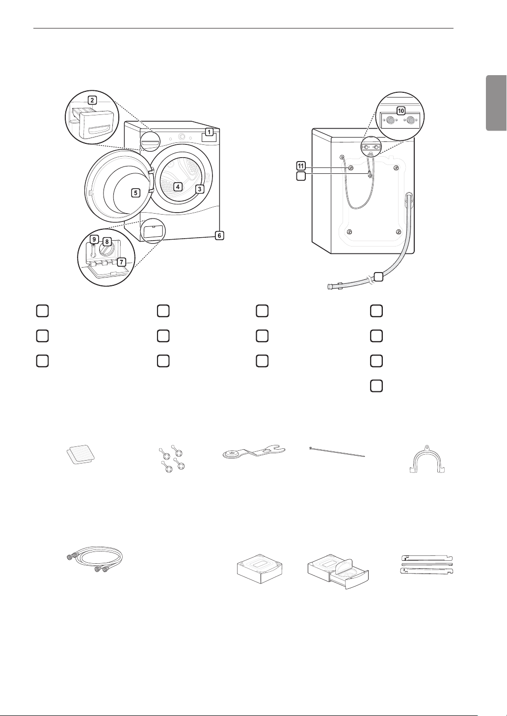
Parts
Control Panel
1
Detergent Dispenser
Drawer
Door Seal
3
Drum
4
Door
Leveling Feet
6
12
Drain Pump Filter Cover
7
Drain Pump Filter
Drain Hose
9
13
Water Inlets
10
Shipping Bolts
Power Cord
12
ENGLISH
Drain Hose
13
Accessories
Included Accessories
Non-skid pads
Hole caps (4)
Required Accessories
Hot/cold water hoses
(sold separately)
NOTE
• The images in this guide may be different from the actual components and accessories, which are subject to
change by the manufacturer without prior notice for product improvement purposes.
• For your safety and for extended product life, use only authorized components. The manufacturer is not
responsible for product malfunction or accidents caused by the use of separately purchased unauthorized
components or parts.
Wrench
Optional Accessories
Pedestal or Pedestal washer
(sold separately)
Tie strap
Elbow bracket
(for securing drain
hose)
Stacking Kit
(sold separately)
Page 2
8 INSTALLATION
INSTALLATION
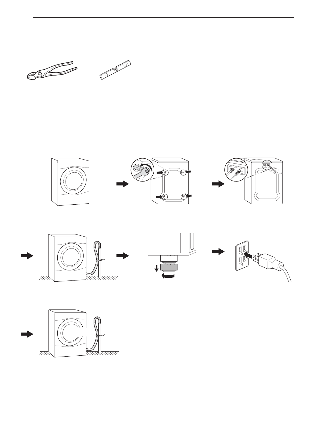
Tools Needed
Pliers
Level
Installation Overview
Please read the following installation instructions rst after purchasing this product or transporting it to another
location.
Choosing the proper location
Unpacking and removing
shipping bolts
Connecting the water lines
Connecting the drain line
TEST!
Testing the washer
Leveling the washer Connecting to the power
supply
Page 3
Product Specications
The appearance and specications listed in this manual may vary due to constant product improvements.
Electrical requirements 120 VAC @ 60 Hz
Min. / Max. water pressure 20 – 120 psi (138–827 kPa)
Dimensions
Net weight 187.4 lb (85 kg)
Max spin speed 1300 RPM
WARNING
• Moving or installation of the appliance requires two or more people. Failure to follow these instructions may
result in injury.
• Store and install the appliance where it will not be exposed to temperatures below freezing or exposed to
outdoor weather conditions. Failure to follow this warning can cause product or part failure, serious injury,
re, electric shock, or death.
• Properly ground the washer to conform with all governing codes and ordinances. Failure to follow this
warning can cause serious injury, re, electric shock, or death.
• To reduce the risk of electric shock, do not install the appliance in humid spaces. Failure to follow this
warning can cause serious injury, re, electric shock, or death.
• To ensure proper airow, do not block the large opening on the bottom of the washer with carpeting or other
materials.
• Do not remove the ground prong. Do not use an adapter or extension cord. Plug into a grounded 3-prong
outlet. Failure to follow this warning can cause serious injury, re, electric shock, or death.
• Certain internal parts are intentionally not grounded and may present a risk of electric shock only during
servicing. Service personnel - Do not contact the following parts while the appliance is energized: pump,
valve, motor, control board.
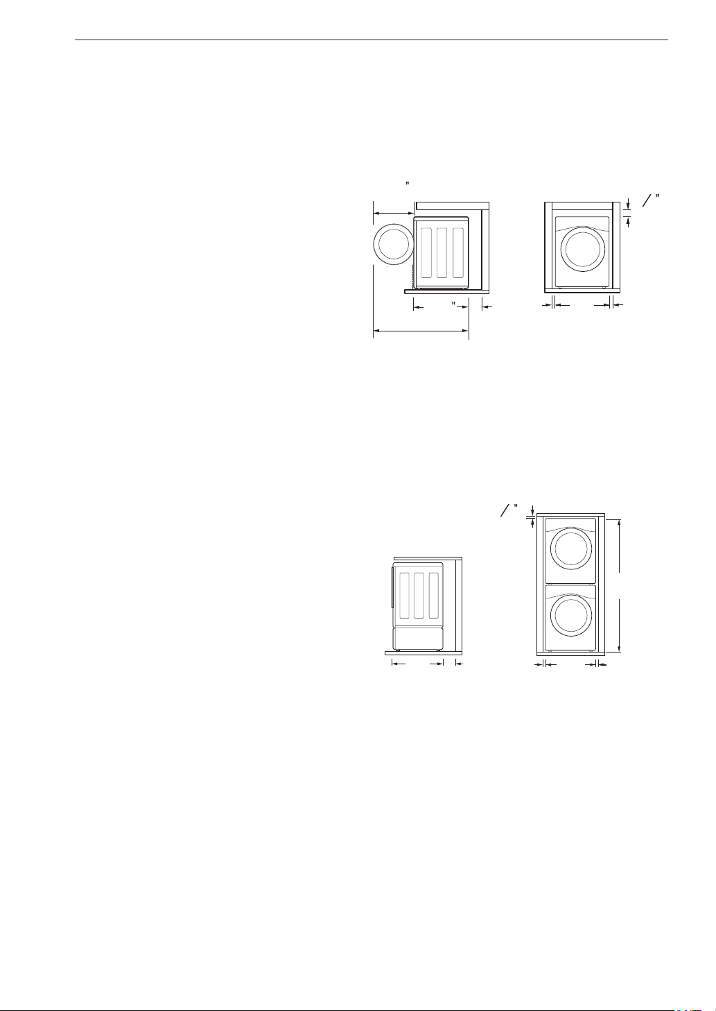
70 cm(W) X 77 cm(D) X 99 cm(H), 139.6 cm (D with door open)
27”(W) X 30 ¼”(D) X 39”(H), 55” (D with door open)
9INSTALLATION
ENGLISH
Page 4
10 INSTALLATION
)
(139.6 cm)
24
¾
(77 cm)
(10 cm)
(70 cm)
(2.5 cm)
(2.5 cm)
(196.8 cm)
13
Choosing the Proper
Location
Install the washer on a solid oor that is strong and
rigid enough to support the weight of the washer,
even when fully loaded, without exing or bouncing.
If the oor has too much ex, you may need to
reinforce it to make it more rigid. If the oor is not
solid, it may cause severe vibration and noise.
NOTE
• Before installing the washer, make sure the oor
is clean, dry and free of dust, dirt, water and oil so
the washer feet cannot slide easily. Leveling feet
that can move or slide on the oor can contribute to
excess vibration and noise due to poor contact with
the oor.
• If a drip pan must be used, take extra care to follow
the instructions provided with the drip pan and make
sure the leveling feet are adjusted for rm and even
contact with the pan. Use of drip pans and failure to
properly level the machine may result in increased
vibration and noise during operation.
• Allow for sufcient space between the walls and the
washer for installation.
Power Outlet
• The power outlet must be within 60 inches (1.5 m)
of either side of the washer.
• The appliance and outlet must be positioned so that
the plug is easily accessible.
• Do not overload the outlet with more than one
appliance.
• The outlet must be grounded in accordance with
current electrical wiring codes and regulations.
• Use a time-delay fuse or circuit breaker.
NOTE
• The washer must be installed on rm ooring to
minimize vibration during the spin cycle. Concrete
ooring is best, but a wood oor is sufcient,
provided it is built to FHA standards.
Floor Installation
(62.6 cm)
1" 1"
(77 cm)
55"
30
¼
4"
(10 cm)
27"
(70 cm)(2.5 cm) (2.5 cm)
To ensure sufcient clearance for water lines, the
drain line and airow, allow minimum clearances of
at least 1 inch (2.5 cm) at the sides and 4 inches (10
cm) behind the unit. Be sure to allow for wall, door,
or oor moldings that may increase the required
clearances.
13
64
(0.5 cm
Stacked or Pedestal Installation
64
(0.5 cm)
77 ½"
NOTE
• It is the personal responsibility and obligation of the
product owner to have a proper outlet installed by
qualied service personnel.
Flooring
• To minimize noise and vibration, the washer must
be installed on a solidly constructed oor.
• Allowable slope under the entire washer is a
maximum 1 inch (2.5 cm) difference from side to
side or from front to back.
• Installing on carpeting and soft tile surfaces is not
recommended.
• Never install the washer on a platform or weakly
supported structure.
30 ¼"
4"
1"
27"
1"
NOTE
• Refer to the instructions packaged with the optional
pedestal kit before installing with a pedestal kit.
• Do not use a drip pan with a pedestal or pedestal
washer installation as it can block the drawer. Using
a drip pan may result in increased vibration and
noise during operation.
Page 5
11INSTALLATION
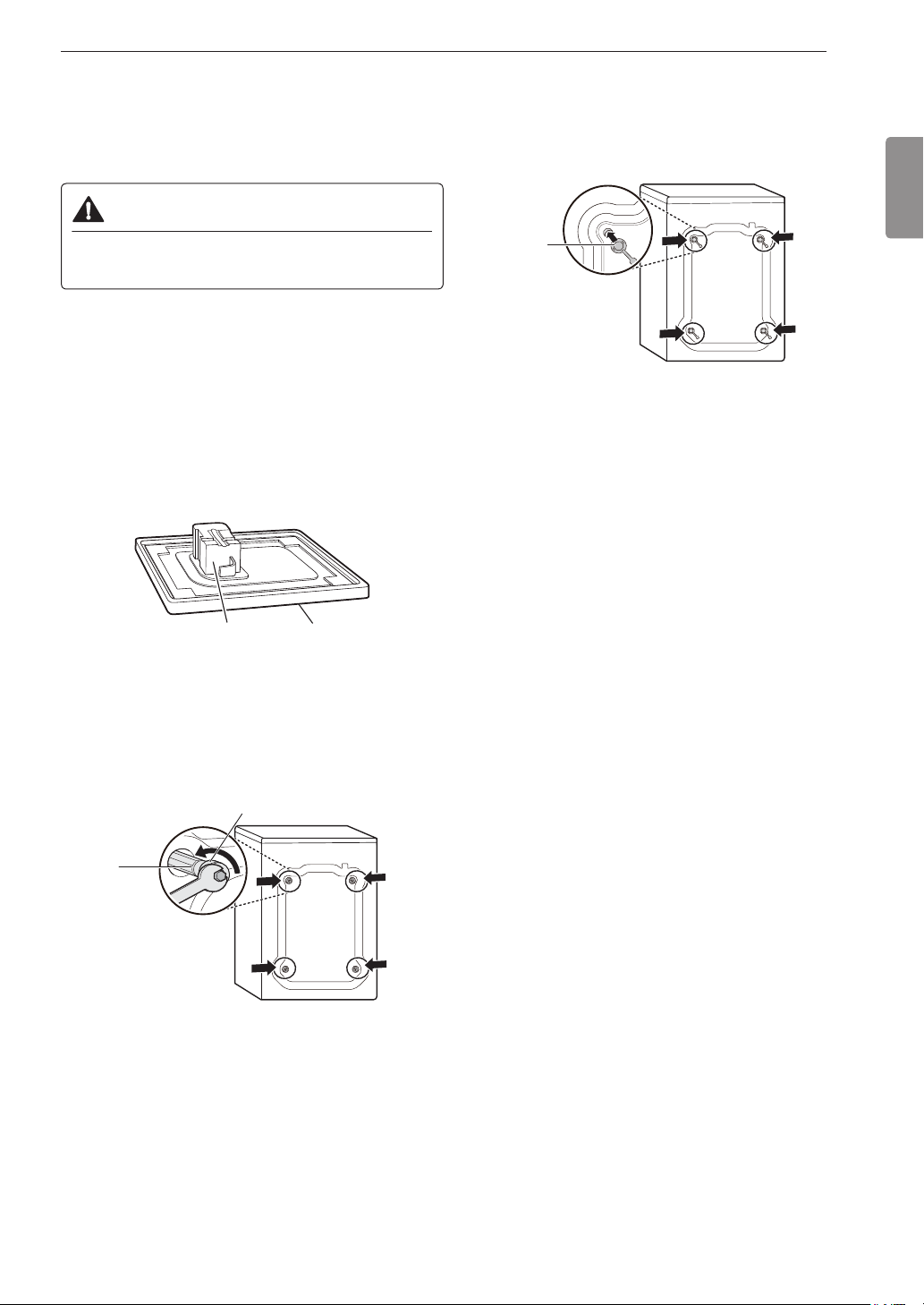
Unpacking and Removing
Shipping Bolts
Unpack all shipping materials from the washer for
proper operation and inspect it for shipping damage.
CAUTION
• Failure to remove shipping materials can cause
excessive noise and vibration.
Lift the washer off the foam base.
1
After removing the carton and shipping material,
lift the washer off the foam base. Make sure the
plastic tub support comes off with the base and is
not stuck to the bottom of the washer.
If you must lay the washer down to remove the
base packaging materials, always protect the side
of the washer and lay it carefully on its side. Do
not lay the washer on its front or back.
Install the hole caps.
3
Locate the four hole caps included in the
accessory pack and install them in the shipping
bolt holes.
Cap
NOTE
• Save the bolt assemblies for future use. To prevent
damage to internal components, do not transport
the washer without reinstalling the shipping bolts.
• Failure to remove shipping bolts and retainers may
cause severe vibration and noise, which can lead
to permanent damage to the washer. The cord is
secured to the back of the washer with a shipping
bolt to help prevent operation with shipping bolts in
place.
ENGLISH
Foam tub
support
Remove the bolt assemblies.
2
Starting with the bottom two shipping bolts, use
the wrench (included) to fully loosen all four
shipping bolts by turning them counterclockwise.
Remove the bolt assemblies by wiggling them
slightly while pulling them out.
Shipping
bolt
Carton base
Retainer
Page 6

12 INSTALLATION
Connecting the Water Lines
To avoid the risk of costly water damage, purchase
and install new inlet hoses when installing the
washer.
Check the ttings and seals.
1
Inspect the threaded tting on each hose and
make sure there is a rubber seal in place in both
ends of each hose to prevent leaking.
Rubber seal Rubber seal
Water hose (to water
inlet on washer)
Connect the water supply hoses.
2
Connect the water supply hoses to the hot and
cold water faucets tightly by hand and then
tighten another 2/3 turn with pliers. Connect the
blue hose to a cold water faucet and the red hose
to a hot water faucet.
Water hose (to tap)
Attach the water lines to the back of the
4
washer.
Attach the hot water line to the hot water inlet on
the back of the washer. Attach the cold water line
to the cold water inlet on the back of the washer.
Tighten the ttings securely. Turn ON both faucets
all the way and check for leaks at both ends of the
hoses.
Cold
water
inlet
Hot water
inlet
WARNING
• Do not overtighten the hoses or cross-thread the
hose ttings. Overtightening or cross-threading
can damage the valves or couplings, resulting in
leaking and property damage.
• Do not reuse old hoses. Use only new hoses
when installing the washer. Old hoses could leak
or burst causing ooding and property damage.
Contact an LG Customer Information Center for
assistance in buying hoses.
Flush out the inlet hoses.
3
After connecting the inlet hoses to the water
faucets, turn on the water faucets to ush out
foreign substances (dirt, sand or sawdust) in the
water lines. Let water drain into a bucket, and
check the water temperature to make sure you've
connected the hoses to the correct faucets.
NOTE
• Periodically check the hoses for cracks, leaks, and
wear, and replace the hoses every ve years. Do
not stretch the water hoses intentionally, and make
sure that they are not pinched, crushed or kinked by
other objects.
• Water supply pressure must be between 20 psi
and 120 psi (138 – 827 kPa). If the water supply
pressure is more than 120 psi, a pressure reducing
valve must be installed.
• To provide optimum washing performance, the hot
water temperature should be set at 120 – 130 °F
(48 – 54 °C) and the cold at 60 °F (15 °C).
• The washer should never be installed or stored in a
location subject to freezing temperatures. Damage
to the water lines and internal mechanisms of the
washer can result. If the washer was exposed to
freezing temperatures prior to installation, allow it to
stand at room temperature for several hours before
use and check for leaks prior to operation.
• Do not use ood-preventing hoses with auto shutoff
devices. The devices can be tripped during ll and
prevent the machine from lling properly.
Page 7

13INSTALLATION
Connecting the Drain Hose
Connect the drain hose to either a standpipe or
laundry tub.
NOTE
• The drain hose should always be properly secured.
Failure to properly secure the drain hose can result
in ooding and property damage.
• The drain must be installed in accordance with any
applicable local codes and regulations.
• Make sure that the drain hose is not stretched,
pinched, crushed, or kinked.
• Do not install the drain hose with the end lower than
29.5 inches (0.7 m) or higher than 96 inches
(2.4 m) above the bottom of the washer or more
than 60 inches (1.5 m) away from the washer.
• Never create an airtight seal between the hose and
the drain with tape or other means. If no air gap
is present, water can be siphoned out of the tub
resulting in poor wash/rinse performance or clothing
damage.
Option 1: Standpipe
Clip the end of the hose into the elbow
1
bracket.
Connect the elbow bracket within 4 inches
(10 cm) of the end of the drain hose. If the drain
hose is extended more than 4 inches (10 cm)
beyond the end of the elbow bracket, mold or
microorganisms could spread to the inside of the
washer.
Option 2: Laundry Tub
Clip the end of the hose into the elbow
1
bracket.
Connect the elbow bracket within 4 inches
(10 cm) of the end of the drain hose. If the drain
hose is extended more than 4 inches (10 cm)
beyond the end of the elbow bracket, mold or
microorganisms could spread to the inside of the
washer.
No more than
4 inches (10 cm)
Elbow bracket
Hang the end of the drain hose over the side
2
of the laundry tub.
Elbow bracket
Drain hose
Use a tie strap to secure the drain hose in
3
place.
ENGLISH
No more than
4 inches (10 cm)
Elbow bracket
Insert the end of the drain hose into the
2
standpipe.
Drain hose
Use a tie strap to secure the drain hose in
3
place.
Elbow bracket
Page 8

14 INSTALLATION
Leveling the Washer
The drum of your new washer spins at very high
speeds. To minimize vibration, noise, and unwanted
movement, the oor must be a level, solid surface.
NOTE
• Adjust the leveling feet only as far as necessary to
level the washer. Extending the leveling feet more
than necessary can cause the washer to vibrate.
• Before installing the washer, make sure that the
oor is clean, dry and free of dust, dirt, water and
oil so the washer feet cannot slide easily. Feet
that move or slide on the oor can contribute to
excessive vibration and noise due to poor contact
with the oor.
Position the washer in its nal location.
1
Take special care not to pinch, strain, or crush the
water and drain lines. If you have a carpenter's
level, you can place it across the top of the
washer. The slope beneath the washer should not
exceed 1 inch, and all four leveling feet must rest
rmly on the oor.
Level
Recheck the washer’s levelness.
4
Push or rock the top edges of the washer gently
to make sure the washer does not rock. If the
washer rocks, repeat steps 1-3.
CAUTION
• Using the washer without leveling it may cause
excess vibration and noise, leading to a machine
malfunction.
• Extend the leveling feet only to level the washer.
If you extend the leveling feet unnecessarily, it
may cause abnormal vibration of the washer.
Using Non-Skid Pads
If you install the washer on a slippery surface, it
may move because of excessive vibration. Incorrect
leveling may cause malfunction through noise and
vibration. If this occurs, install the non-skid pads
under the leveling feet and adjust the level.
Clean the oor to attach the non-skid pads.
1
Use a dry rag to remove and clean foreign objects
or moisture. If moisture remains, the non-skid
pads may slip.
Adjust the lower leveling feet.
2
Turn in one direction to raise the washer or the
other direction to lower it.
Raise Lower
Tighten the locknuts.
3
Turn the locknuts counter-clockwise and tighten
them when the washer is level.
Lock nut
Tighten all 4 lock
nuts securely
Adjust the level after placing the washer in the
2
1"
installation area.
Place the adhesive side of the non-skid pad
3
on the oor.
It is most effective to install the non-skid pads
under the front leveling feet. If it is hard to place
the pads under the front leveling feet, place them
under the back leveling feet.
This side up
Adhesive
side
Remove backing
Recheck the washer’s levelness.
4
Push or rock the top edges of the washer gently
to make sure that the washer does not rock. If the
washer rocks, level the washer again.
Page 9

15INSTALLATION
Connecting to the Power
Supply
The washer should be plugged into a 120-VAC, 60
Hz grounded 3-prong outlet. Plug in the washer.
WARNING
• Do not use a worn or damaged power cord or
power plug. Replace or repair it immediately.
Failure to do so may result in death, re, electric
shock, or malfunction.
• Do not modify the power cord and plug provided
with the appliance. Take care not to damage it
when installing or moving the washer. Failure to
do so may result in death, re, electric shock, or
malfunction.
• Make sure that the washer is grounded.
• Connect this washer to a grounded outlet
conforming to the rating prior to use. Failure
to do so may result in re, electric shock, or
malfunction.
• Do not damage or cut off the ground prong of
the power cord. Doing so may cause death, re,
electric shock, or product malfunction.
• Improper connection of the equipment-grounding
conductor can result in risk of electric shock.
Check with a qualied electrician or service
technician if you are in doubt as to whether the
appliance is properly grounded. If it does not t
the outlet, have a proper outlet installed by a
qualied electrician
• The appliance and outlet must be positioned so
that the plug is easily accessible.
• Do not use adapters or extension cords. Doing
so may result in serious injury, re, electric
shock, or death.
• For best performance, plug the washer into
its own individual outlet. This helps prevent
overloading house wiring circuits which could
cause a re hazard from overheated wires.
• If necessary, use a new, UL-listed 3-prong
adapter or 3-wire extension cord with a 3-prong
(grounding) plug rated at no less than the branch
circuit. Do not use an extension cord longer
than 3 feet. Failure to follow these warnings may
result in serious injury, re, electric shock, or
death.
Testing the Washer
Check if the washer is properly installed and run a
test cycle.
Load the washer with 6 pounds of laundry
1
(approximately 6 thick bath towels).
Press the Power button.
2
Press the Rinse+Spin button.
3
Press the Start/Pause button.
4
The wash cycle starts.
Check if water is supplied, that the machine does
5
not rock or vibrate excessively, and that it drains
well during the spin cycle.
NOTE
• If water leaks during water supply, see Connecting
the Water Lines to connect them properly.
• If the washer rocks and vibrates excessively, see
Leveling the Washer to level it again.
• If the drain does not work, see Connecting the Drain
Hose to install the hose properly.
ENGLISH
Page 10

16 OPERATION
OPERATION
Using the Washer
WARNING
• To reduce the risk of re, electric shock, or injury to persons, read the SAFETY INSTRUCTIONS before
operating this appliance.
Sort Laundry and Load the Washer
1
Sort laundry by fabric type, soil level, color and load size, as needed. Open the
door and load items into the washer.
If using detergent pods, place pod in drum before loading laundry.
Add Cleaning Products.
2
Add the proper amount of HE (High-Efciency) detergent to the detergent
dispenser. If desired, add bleach or fabric softener to the appropriate areas of
the dispenser drawer. Do not place liquid or powdered detergent pods in the
dispenser.
Turn on the Washer
3
Press the Power button to turn on the washer. The lights above the cycle
buttons will illuminate and a chime will sound.
Select a Cycle
4
Turn the Cycle Selector Knob until the desired cycle is selected. The preset
Temp., Spin, Soil and option settings for that cycle will be shown. Pressing the
Start/Pause button without selecting a cycle will cause the Normal cycle to
begin immediately.
Adjust Settings
5
Default settings for the selected cycle can now be changed, if desired, using the
cycle modier and option buttons.
• Not all modiers and options are available on all cycles. A different chime will
sound and the LED will not come on if the selection is not allowed.
Begin Cycle
6
Press the Start/Pause button to begin the cycle. The washer will agitate briey
without water to measure the weight of the load. If the Start/Pause button is not
pressed within 60 minutes, the washer will shut off and all settings will be lost.
End of Cycle
7
When the cycle is nished, a melody will sound. Immediately remove your
clothing from the washer to reduce wrinkling. Check around the door seal when
removing the load for small items that may be caught in the seal.
NOTE
• The washer rotates the laundry in a way that allows it to use less water while still fully saturating your clothing.
It is normal to not be able to see water during the wash cycle.
• If the temperature or the water level inside the machine is too high, the door will not unlock when the Start/
Pause button is pressed. To open the door in these circumstances, press Add Garments. To stop a cycle and
drain the water completely, turn the power off, then on, and then press Rinse+Spin.
Page 11

17OPERATION
Loading the Washer
• Check and empty pockets. Paper clips, coins,
matches, etc. can damage clothing and the washer.
• Close zippers and hooks, and tie drawstrings to
prevent snagging or tangling of clothes.
• Pretreat heavily stained areas for best results.
• Combine large and small items in a load. Load large
items rst. Large items should not be more than half
of total load.
• The washer can be fully loaded, but the drum
should not be tightly packed with items. The door of
the washer must close easily.
• Do not wash single small items. Add 1-2 similar
items to the load to prevent an out-of-balance load.
• Wash thick, bulky items individually. Heavy blankets,
comforters, bedspreads, or pet beds can get
tangled or cause an unbalanced load if combined
with other items.
• Do not wash/spin waterproof items. Washing
raincoats or sleeping bags may result in abnormal
vibration or may cause the load to bounce, which
could damage the drum.
• Wash small, light items in a mesh bag. Items like
underwear can get caught in the door seal, and
a brassiere hook may damage other items or the
drum.
• Brush off heavy soil, dust, and hair from items
before washing. Excess dirt or sand can abrade
other fabrics and lead to poor wash performance.
• For best performance, load clothes as shown.
This manual contains an abbreviated Operation
section. For the complete Operation section, scan
the QR code below or visit: https://us.smartthinq.
com/images/pdfmanual/VH_FL_VICTOR_799_
MFL68005567_EN.pdf
• Sorting Laundry
• Adding Cleaning Products
• Control Panel
• Wash Cycles
• Cycle Guide
• Cycle Modier Buttons
• Option Buttons
ENGLISH
4
3
1
- Load clothes loosely, and do not overll the drum.
Clothes need room to circulate in order to get
clean.
- Do not press down on items while stacking them in
the drum.
2
Page 12

18 SMART FUNCTIONS
SMART FUNCTIONS
LG SmartThinQ Application
The LG SmartThinQ application allows you to
communicate with the appliance using a smartphone.
Before Using LG SmartThinQ
• For appliances with the or logo
Use a smartphone to check the strength of
1
the wireless router (Wi-Fi network) near the
appliance.
• If the distance between the appliance and the
wireless router is too far, the signal strength
becomes weak. It may take a long time to
register or installation may fail.
Turn off the Mobile data or Cellular Data on your
2
smartphone.
• If the appliance is having trouble connecting to the
Wi-Fi network, it may be too far from the router.
Purchase a Wi-Fi repeater (range extender) to
improve the Wi-Fi signal strength.
• The network connection may not work properly
depending on the Internet service provider.
• The Wi-Fi connection may not connect or may
be interrupted because of the home network
environment.
• If the appliance cannot be registered due to
problems with the wireless signal transmission,
unplug the appliance and wait about a minute
before trying again.
• If the rewall on your wireless router is enabled,
disable the rewall or add an exception to it.
• The wireless network name (SSID) should be a
combination of English letters and numbers. (Do not
use special characters.)
• Smartphone user interface (UI) may vary depending
on the mobile operating system (OS) and the
manufacturer.
• If the security protocol of the router is set to WEP,
network setup may fail. Change the security
protocol (WPA2 is recommended), and register the
product again.
Connect your smartphone to the wireless router.
3
NOTE
• To verify the Wi-Fi connection, check that Wi-Fi
icon on the control panel is lit.
• The appliance supports 2.4 GHz Wi-Fi networks
only. To check your network frequency, contact your
Internet service provider or refer to your wireless
router manual.
• LG SmartThinQ is not responsible for any network
connection problems or any faults, malfunctions, or
errors caused by network connection.
• The surrounding wireless environment can make
the wireless network service run slowly.
Installing the LG SmartThinQ
Application
Search for the LG SmartThinQ application from the
Google Play Store or Apple App Store on a smart
phone. Follow instructions to download and install the
application.
Page 13

19SMART FUNCTIONS
LG SmartThinQ Application Features
• For appliances with the or logo
Washer Cycle (Remote Start, Downloaded)
Set or download any preferred cycle and operate by
remote control.
Tub Clean Coach
This function shows how many cycles remain before
it is time to run the Tub Clean cycle.
Smart Diagnosis™
This function provides useful information for
diagnosing and solving issues with the appliance
based on the pattern of use.
Energy Monitoring
The washer energy usage is affected by the cycles
and options so you may see some changes in energy
usage from one cycle to another.
Push Alerts
When the cycle is complete or the appliance has
problems, you have the option of receiving push
notications on a smart phone.
Settings
Set the product nickname and delete product.
Using Washer Cycle
Remote Start
Use a smart phone to control the appliance remotely
or check to see how much time is left in the cycle.
Using Remote Start
Press the Power button.
1
Load the laundry.
2
Press and hold Remote Start button for 3
3
seconds to enable the Remote Start function.
Start a cycle from the LG SmartThinQ application
4
on your smart phone.
NOTE
• Once the Remote Start mode is enabled, you can
start a cycle from the LG SmartThinQ smartphone
application. If the cycle is not started, the machine
will wait to start the cycle until it is turned off
remotely from the application or the Remote Start
mode is disabled.
• When Remote Start is turned on, the door is
automatically locked.
ENGLISH
NOTE
•
If you change your wireless router, Internet service
provider, or password, delete the registered
appliance from the LG SmartThinQ application and
register it again.
• This information is current at the time of publication.
The application is subject to change for product
improvement purposes without notice to users.
Disabling Remote Start
When the Remote Start is activated, press and hold
the Remote Start button for 3 seconds.
Downloaded
Download new and specialized cycles that are not
included in the standard cycles on the appliance.
Appliances that have been successfully registered
can download a variety of specialty cycles specic to
the appliance.
Only one cycle can be stored on the appliance at a
time.
Once cycle download is completed in the appliance,
the appliance keeps the downloaded cycle until a
new cycle is downloaded.
Page 14

20 SMART FUNCTIONS
Wireless LAN Module Specications
Model LCW-004
Frequency Range 2412 - 2462 MHz
IEEE 802.11 b : 22.44 dBm
Output Power
(Max)
FCC Notice (For transmitter module
contained in this product)
This equipment has been tested and found to comply
with the limits for a Class B digital device, pursuant
to Part 15 of the FCC Rules. These limits are
designed to provide reasonable protection against
harmful interference in a residential installation. This
equipment generates, uses, and can radiate radio
frequency energy and, if not installed and used in
accordance with the instructions, may cause harmful
interference to radio communications. However, there
is no guarantee that interference will not occur in a
particular installation. If this equipment does cause
harmful interference to radio or television reception,
which can be determined by turning the equipment
off and on, the user is encouraged to try to correct
the interference by one or more of the following
measures:
• Reorient or relocate the receiving antenna.
• Increase the separation between the equipment and
the receiver.
• Connect the equipment to an outlet on a circuit
different from that to which the receiver is
connected.
• Consult the dealer or an experienced radio/TV
technician for help.
This device complies with part 15 of the FCC Rules.
Operation is subject to the following two conditions:
1) This device may not cause harmful interference
and
2) This device must accept any interference received,
including interference that may cause undesired
operation of the device.
Any changes or modications in construction of this
device which are not expressly approved by the party
responsible for compliance could void the user’s
authority to operate the equipment.
IEEE 802.11 g : 24.68 dBm
IEEE 802.11 n : 24.11 dBm
FCC RF Radiation Exposure Statement
This equipment complies with FCC radiation
exposure limits set forth for an uncontrolled
environment. This transmitter must not be co-located
or operating in conjunction with any other antenna or
transmitter.
This equipment should be installed and operated with
a minimum distance of 20 cm (7.8 inches) between
the antenna and your body. Users must follow the
specic operating instructions for satisfying RF
exposure compliance.
Industry Canada Statement (For transmitter
module contained in this product)
This device complies with Industry Canada’s
applicable licence-exempt RSSs. Operation is subject
to the following two conditions:
1) This device may not cause interference; and
2) This device must accept any interference,
including interference that may cause undesired
operation of the device.
IC Radiation Exposure Statement
This equipment complies with IC radiation exposure
limits set forth for an uncontrolled environment.
This equipment should be installed and operated with
a minimum distance of 20 cm (7.8 inches) between
the antenna and your body.
NOTE
• THE MANUFACTURER IS NOT RESPONSIBLE
FOR ANY RADIO OR TV INTERFERENCE
CAUSED BY UNAUTHORIZED MODIFICATIONS
TO THIS EQUIPMENT. SUCH MODIFICATIONS
COULD VOID THE USER’S AUTHORITY TO
OPERATE THE EQUIPMENT.
Open Source Software Notice
Information
To obtain the source code under GPL, LGPL, MPL,
and other open source licenses, that is contained in
this product, please visit http://opensource.lge.com.
In addition to the source code, all referred license
terms, warranty disclaimers and copyright notices are
available for download.
LG Electronics will also provide open source code
to you on CD-ROM for a charge covering the cost
of performing such distribution (such as the cost of
media, shipping, and handling) upon email request
to opensource@lge.com. This offer is valid for a
period of three years after our last shipment of this
product. This offer is valid to anyone in receipt of this
information.
Page 15

21SMART FUNCTIONS
Smart Diagnosis™ Function
Should you experience any problems with the
appliance, it has the capability of transmitting data
via your telephone to the LG Customer Information
Center. NFC or Wi-Fi equipped models can also
transmit data to a smartphone using the LG
SmartThinQ application.
Smart Diagnosis™ through the
Customer Information Center
• For appliances with the or logo
This method allows you to speak directly to our
trained specialists. The specialist records the data
transmitted from the appliance and uses it to analyze
the issue, providing a fast and effective diagnosis.
Call the LG Electronics Customer Information
1
Center at:
(LG U.S.A.) 1-800-243-0000
(LG Canada) 1-888-542-2623
When instructed to do so by the call center, place
2
the mouthpiece of the phone close to the Smart
Diagnosis™ icon. Do not press any other buttons.
NOTE
• Smart Diagnosis™ cannot be activated unless
the appliance can be turned on using the Power
button. If the appliance cannot be turned on,
troubleshooting must be done without using Smart
Diagnosis™.
• For best results, do not move the phone while the
tones are being transmitted.
• If the call center agent is not able to get an accurate
recording of the data, you may be asked to try
again.
• The Smart Diagnosis™ function depends on the
local call quality.
• Bad call quality may result in poor data transmission
from your phone to the call center, which could
cause Smart Diagnosis™ to malfunction.
LG SmartThinQ Smart Diagnosis™
• For appliances with the or logo
Use the Smart Diagnosis feature in the LG
SmartThinQ application for help diagnosing issues
with the appliance without the assistance of the LG
Customer Information Center.
Follow the instructions in the LG SmartThinQ
application to perform a Smart Diagnosis using your
smartphone.
NOTE
• Smart Diagnosis™ cannot be activated unless
the appliance can be turned on using the Power
button. If the appliance cannot be turned on,
troubleshooting must be done without using Smart
Diagnosis™.
ENGLISH
Press and hold Temp. for three seconds.
3
Keep the phone in place until the tone
4
transmission has nished.
• For best results, do not move the phone while
the tones are being transmitted.
• If the call center agent is not able to get an
accurate recording of the data, you may be
asked to try again.
Once the countdown is over and the tones have
5
stopped, resume your conversation with the call
center agent, who will then be able to assist you
using the information transmitted for analysis.
 Loading...