

Page 1
8 INSTALLATION
INSTALLATION
Tools Needed
Pliers
Level
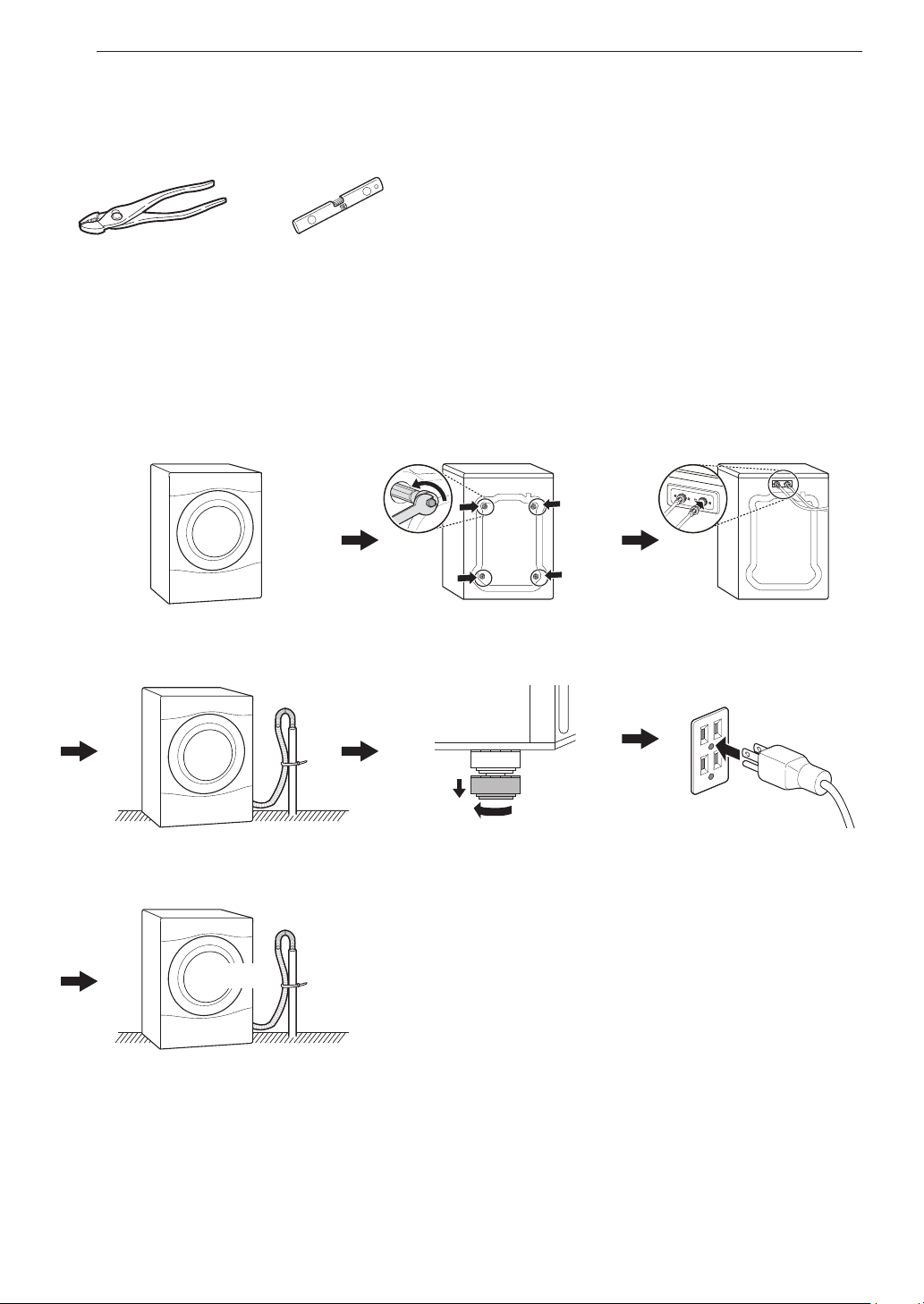
Installation Overview
Please read the following installation instructions rst after purchasing this product or transporting it to another
location.
Choosing the proper location
Unpacking and removing
shipping bolts
Connecting the water lines
Connecting the drain line
TEST!
Testing the washer
Leveling the washer Connecting to the power
supply
Page 2
Product Specications
The appearance and specications listed in this manual may vary due to constant product improvements.
Electrical requirements 120 VAC @ 60 Hz
Min. / Max. water pressure 20 – 120 psi (138–827 kPa)
Dimensions
Net weight 187.4 lb (85 kg)
Max spin speed 1300 RPM
WARNING
• Moving or installation of the appliance requires two or more people. Failure to follow these instructions may
result in injury.
• Store and install the appliance where it will not be exposed to temperatures below freezing or exposed to
outdoor weather conditions. Failure to follow this warning can cause product or part failure, serious injury,
re, electric shock, or death.
• Properly ground the washer to conform with all governing codes and ordinances. Failure to follow this
warning can cause serious injury, re, electric shock, or death.
• To reduce the risk of electric shock, do not install the appliance in humid spaces. Failure to follow this
warning can cause serious injury, re, electric shock, or death.
• To ensure proper airow, do not block the large opening on the bottom of the washer with carpeting or other
materials.
• Do not remove the ground prong. Do not use an adapter or extension cord. Plug into a grounded 3-prong
outlet. Failure to follow this warning can cause serious injury, re, electric shock, or death.
• Certain internal parts are intentionally not grounded and may present a risk of electric shock only during
servicing. Service personnel - Do not contact the following parts while the appliance is energized: pump,
valve, motor, control board.
70 cm(W) X 77 cm(D) X 99 cm(H), 139.6 cm (D with door open)
27”(W) X 30 ¼”(D) X 39”(H), 55” (D with door open)
9INSTALLATION
ENGLISH
Page 3
10 INSTALLATION
)
(139.6 cm)
24
¾
(77 cm)
(10 cm)
(70 cm)
(2.5 cm)
(2.5 cm)
(196.8 cm)
13
Choosing the Proper
Location
Install the washer on a solid oor that is strong and
rigid enough to support the weight of the washer,
even when fully loaded, without exing or bouncing.
If the oor has too much ex, you may need to
reinforce it to make it more rigid. If the oor is not
solid, it may cause severe vibration and noise.
NOTE
• Before installing the washer, make sure the oor
is clean, dry and free of dust, dirt, water and oil so
the washer feet cannot slide easily. Leveling feet
that can move or slide on the oor can contribute to
excess vibration and noise due to poor contact with
the oor.
• If a drip pan must be used, take extra care to follow
the instructions provided with the drip pan and make
sure the leveling feet are adjusted for rm and even
contact with the pan. Use of drip pans and failure to
properly level the machine may result in increased
vibration and noise during operation.
• Allow for sufcient space between the walls and the
washer for installation.
Power Outlet
• The power outlet must be within 60 inches (1.5 m)
of either side of the washer.
• The appliance and outlet must be positioned so that
the plug is easily accessible.
• Do not overload the outlet with more than one
appliance.
• The outlet must be grounded in accordance with
current electrical wiring codes and regulations.
• Use a time-delay fuse or circuit breaker.
NOTE
• The washer must be installed on rm ooring to
minimize vibration during the spin cycle. Concrete
ooring is best, but a wood oor is sufcient,
provided it is built to FHA standards.
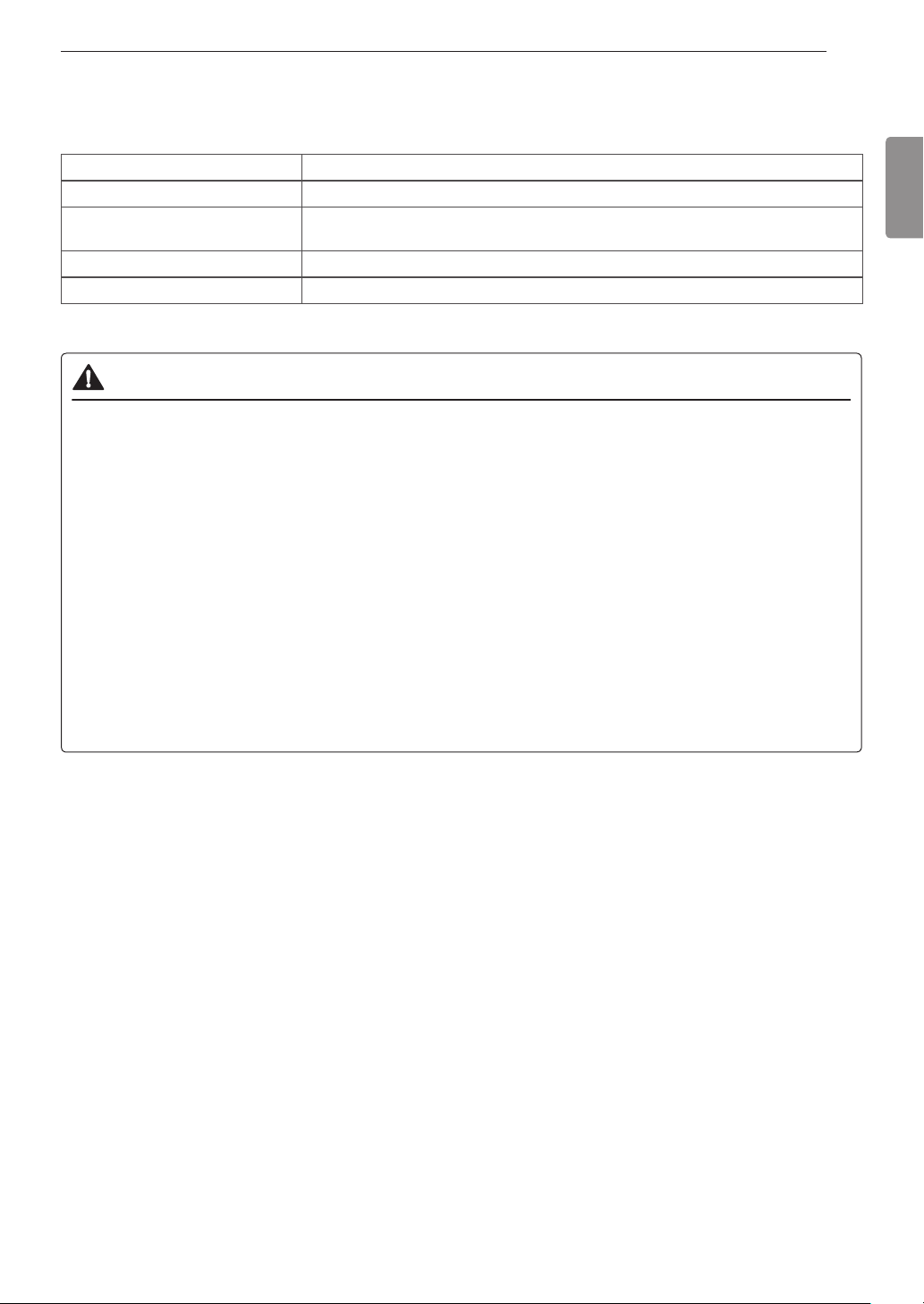
Floor Installation
(62.6 cm)
1" 1"
(77 cm)
55"
30
¼
4"
(10 cm)
27"
(70 cm)(2.5 cm) (2.5 cm)
To ensure sufcient clearance for water lines, the
drain line and airow, allow minimum clearances of
at least 1 inch (2.5 cm) at the sides and 4 inches (10
cm) behind the unit. Be sure to allow for wall, door,
or oor moldings that may increase the required
clearances.
13
64
(0.5 cm
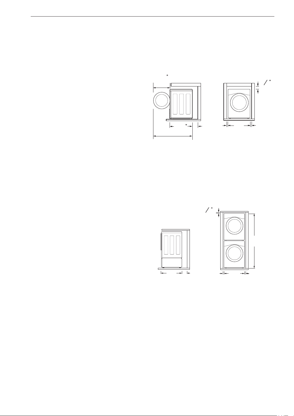
Stacked or Pedestal Installation
64
(0.5 cm)
77 ½"
NOTE
• It is the personal responsibility and obligation of the
product owner to have a proper outlet installed by
qualied service personnel.
Flooring
• To minimize noise and vibration, the washer must
be installed on a solidly constructed oor.
• Allowable slope under the entire washer is a
maximum 1 inch (2.5 cm) difference from side to
side or from front to back.
• Installing on carpeting and soft tile surfaces is not
recommended.
• Never install the washer on a platform or weakly
supported structure.
30 ¼"
4"
1"
27"
1"
NOTE
• Refer to the instructions packaged with the optional
pedestal kit before installing with a pedestal kit.
• Do not use a drip pan with a pedestal or pedestal
washer installation as it can block the drawer. Using
a drip pan may result in increased vibration and
noise during operation.
Page 4

11INSTALLATION
Unpacking and Removing
Shipping Bolts
Unpack all shipping materials from the washer for
proper operation and inspect it for shipping damage.
CAUTION
• Failure to remove shipping materials can cause
excessive noise and vibration.
Lift the washer off the foam base.
1
After removing the carton and shipping material,
lift the washer off the foam base. Make sure the
plastic tub support comes off with the base and is
not stuck to the bottom of the washer.
If you must lay the washer down to remove the
base packaging materials, always protect the side
of the washer and lay it carefully on its side. Do
not lay the washer on its front or back.
Install the hole caps.
3
Locate the four hole caps included in the
accessory pack and install them in the shipping
bolt holes.
Cap
NOTE
• Save the bolt assemblies for future use. To prevent
damage to internal components, do not transport
the washer without reinstalling the shipping bolts.
• Failure to remove shipping bolts and retainers may
cause severe vibration and noise, which can lead
to permanent damage to the washer. The cord is
secured to the back of the washer with a shipping
bolt to help prevent operation with shipping bolts in
place.
ENGLISH
Foam tub
support
Remove the bolt assemblies.
2
Starting with the bottom two shipping bolts, use
the wrench (included) to fully loosen all four
shipping bolts by turning them counterclockwise.
Remove the bolt assemblies by wiggling them
slightly while pulling them out.
Shipping
bolt
Carton base
Retainer
Page 5

12 INSTALLATION
Connecting the Water Lines
To avoid the risk of costly water damage, purchase
and install new inlet hoses when installing the
washer.
Check the ttings and seals.
1
Inspect the threaded tting on each hose and
make sure there is a rubber seal in place in both
ends of each hose to prevent leaking.
Rubber seal Rubber seal
Water hose (to water
inlet on washer)
Connect the water supply hoses.
2
Connect the water supply hoses to the hot and
cold water faucets tightly by hand and then
tighten another 2/3 turn with pliers. Connect the
blue hose to a cold water faucet and the red hose
to a hot water faucet.
Water hose (to tap)
Attach the water lines to the back of the
4
washer.
Attach the hot water line to the hot water inlet on
the back of the washer. Attach the cold water line
to the cold water inlet on the back of the washer.
Tighten the ttings securely. Turn ON both faucets
all the way and check for leaks at both ends of the
hoses.
Cold
water
inlet
Hot water
inlet
WARNING
• Do not overtighten the hoses or cross-thread the
hose ttings. Overtightening or cross-threading
can damage the valves or couplings, resulting in
leaking and property damage.
• Do not reuse old hoses. Use only new hoses
when installing the washer. Old hoses could leak
or burst causing ooding and property damage.
Contact an LG Customer Information Center for
assistance in buying hoses.
Flush out the inlet hoses.
3
After connecting the inlet hoses to the water
faucets, turn on the water faucets to ush out
foreign substances (dirt, sand or sawdust) in the
water lines. Let water drain into a bucket, and
check the water temperature to make sure you've
connected the hoses to the correct faucets.
NOTE
• Periodically check the hoses for cracks, leaks, and
wear, and replace the hoses every ve years. Do
not stretch the water hoses intentionally, and make
sure that they are not pinched, crushed or kinked by
other objects.
• Water supply pressure must be between 20 psi
and 120 psi (138 – 827 kPa). If the water supply
pressure is more than 120 psi, a pressure reducing
valve must be installed.
• To provide optimum washing performance, the hot
water temperature should be set at 120 – 130 °F
(48 – 54 °C) and the cold at 60 °F (15 °C).
• The washer should never be installed or stored in a
location subject to freezing temperatures. Damage
to the water lines and internal mechanisms of the
washer can result. If the washer was exposed to
freezing temperatures prior to installation, allow it to
stand at room temperature for several hours before
use and check for leaks prior to operation.
• Do not use ood-preventing hoses with auto shutoff
devices. The devices can be tripped during ll and
prevent the machine from lling properly.
Page 6

13INSTALLATION
Connecting the Drain Hose
Connect the drain hose to either a standpipe or
laundry tub.
NOTE
• The drain hose should always be properly secured.
Failure to properly secure the drain hose can result
in ooding and property damage.
• The drain must be installed in accordance with any
applicable local codes and regulations.
• Make sure that the drain hose is not stretched,
pinched, crushed, or kinked.
• Do not install the drain hose with the end lower than
29.5 inches (0.7 m) or higher than 96 inches
(2.4 m) above the bottom of the washer or more
than 60 inches (1.5 m) away from the washer.
• Never create an airtight seal between the hose and
the drain with tape or other means. If no air gap
is present, water can be siphoned out of the tub
resulting in poor wash/rinse performance or clothing
damage.
Option 1: Standpipe
Clip the end of the hose into the elbow
1
bracket.
Connect the elbow bracket within 4 inches
(10 cm) of the end of the drain hose. If the drain
hose is extended more than 4 inches (10 cm)
beyond the end of the elbow bracket, mold or
microorganisms could spread to the inside of the
washer.
Option 2: Laundry Tub
Clip the end of the hose into the elbow
1
bracket.
Connect the elbow bracket within 4 inches
(10 cm) of the end of the drain hose. If the drain
hose is extended more than 4 inches (10 cm)
beyond the end of the elbow bracket, mold or
microorganisms could spread to the inside of the
washer.
No more than
4 inches (10 cm)
Elbow bracket
Hang the end of the drain hose over the side
2
of the laundry tub.
Elbow bracket
Drain hose
Use a tie strap to secure the drain hose in
3
place.
ENGLISH
No more than
4 inches (10 cm)
Elbow bracket
Insert the end of the drain hose into the
2
standpipe.
Drain hose
Use a tie strap to secure the drain hose in
3
place.
Elbow bracket
Page 7

14 INSTALLATION
Leveling the Washer
The drum of your new washer spins at very high
speeds. To minimize vibration, noise, and unwanted
movement, the oor must be a level, solid surface.
NOTE
• Adjust the leveling feet only as far as necessary to
level the washer. Extending the leveling feet more
than necessary can cause the washer to vibrate.
• Before installing the washer, make sure that the
oor is clean, dry and free of dust, dirt, water and
oil so the washer feet cannot slide easily. Feet
that move or slide on the oor can contribute to
excessive vibration and noise due to poor contact
with the oor.
Position the washer in its nal location.
1
Take special care not to pinch, strain, or crush the
water and drain lines. If you have a carpenter's
level, you can place it across the top of the
washer. The slope beneath the washer should not
exceed 1 inch, and all four leveling feet must rest
rmly on the oor.
Level
Recheck the washer’s levelness.
4
Push or rock the top edges of the washer gently
to make sure the washer does not rock. If the
washer rocks, repeat steps 1-3.
CAUTION
• Using the washer without leveling it may cause
excess vibration and noise, leading to a machine
malfunction.
• Extend the leveling feet only to level the washer.
If you extend the leveling feet unnecessarily, it
may cause abnormal vibration of the washer.
Using Non-Skid Pads
If you install the washer on a slippery surface, it
may move because of excessive vibration. Incorrect
leveling may cause malfunction through noise and
vibration. If this occurs, install the non-skid pads
under the leveling feet and adjust the level.
Clean the oor to attach the non-skid pads.
1
Use a dry rag to remove and clean foreign objects
or moisture. If moisture remains, the non-skid
pads may slip.
Adjust the lower leveling feet.
2
Turn in one direction to raise the washer or the
other direction to lower it.
Raise Lower
Tighten the locknuts.
3
Turn the locknuts counter-clockwise and tighten
them when the washer is level.
Lock nut
Tighten all 4 lock
nuts securely
Adjust the level after placing the washer in the
2
1"
installation area.
Place the adhesive side of the non-skid pad
3
on the oor.
It is most effective to install the non-skid pads
under the front leveling feet. If it is hard to place
the pads under the front leveling feet, place them
under the back leveling feet.
This side up
Adhesive
side
Remove backing
Recheck the washer’s levelness.
4
Push or rock the top edges of the washer gently
to make sure that the washer does not rock. If the
washer rocks, level the washer again.
Page 8

15INSTALLATION
Connecting to the Power
Supply
The washer should be plugged into a 120-VAC, 60
Hz grounded 3-prong outlet. Plug in the washer.
WARNING
• Do not use a worn or damaged power cord or
power plug. Replace or repair it immediately.
Failure to do so may result in death, re, electric
shock, or malfunction.
• Do not modify the power cord and plug provided
with the appliance. Take care not to damage it
when installing or moving the washer. Failure to
do so may result in death, re, electric shock, or
malfunction.
• Make sure that the washer is grounded.
• Connect this washer to a grounded outlet
conforming to the rating prior to use. Failure
to do so may result in re, electric shock, or
malfunction.
• Do not damage or cut off the ground prong of
the power cord. Doing so may cause death, re,
electric shock, or product malfunction.
• Improper connection of the equipment-grounding
conductor can result in risk of electric shock.
Check with a qualied electrician or service
technician if you are in doubt as to whether the
appliance is properly grounded. If it does not t
the outlet, have a proper outlet installed by a
qualied electrician
• The appliance and outlet must be positioned so
that the plug is easily accessible.
• Do not use adapters or extension cords. Doing
so may result in serious injury, re, electric
shock, or death.
• For best performance, plug the washer into
its own individual outlet. This helps prevent
overloading house wiring circuits which could
cause a re hazard from overheated wires.
• If necessary, use a new, UL-listed 3-prong
adapter or 3-wire extension cord with a 3-prong
(grounding) plug rated at no less than the branch
circuit. Do not use an extension cord longer
than 3 feet. Failure to follow these warnings may
result in serious injury, re, electric shock, or
death.
Testing the Washer
Check if the washer is properly installed and run a
test cycle.
Load the washer with 6 pounds of laundry
1
(approximately 6 thick bath towels).
Press the Power button.
2
Press the Rinse+Spin button.
3
Press the Start/Pause button.
4
The wash cycle starts.
Check if water is supplied, that the machine does
5
not rock or vibrate excessively, and that it drains
well during the spin cycle.
NOTE
• If water leaks during water supply, see Connecting
the Water Lines to connect them properly.
• If the washer rocks and vibrates excessively, see
Leveling the Washer to level it again.
• If the drain does not work, see Connecting the Drain
Hose to install the hose properly.
ENGLISH
 Loading...