

LG WKEX200H*A, WKGX201H*A User Manual

INSTALLATION MANUAL
LAUNDRY CENTER
Read this installation manual thoroughly before installing the
appliance and keep it handy for reference at all times.
ENGLISH ESPAÑOL
WKEX200H*A / WKGX201H*A / WSEX200HNA / WSGX201HNA
MFL71728904
Rev.02_072020
www.lg.com
Copyright © 2020 LG Electronics Inc. All Rights Reserved.

2
TABLE OF CONTENTS
3 IMPORTANT SAFETY
INSTRUCTIONS
3 READ ALL INSTRUCTIONS BEFORE USE
3 WARNING STATEMENTS
7 CAUTION STATEMENTS
8 PRODUCT OVERVIEW
8 Product Features
10 INSTALLATION
10 Before Installing
11 Choosing the Proper Location
13 Unpacking and Removing Shipping Material
13 Connecting Electric Dryers
18 Installing the Dryer Side Vent Kit
18 Venting the Dryer
20 Connecting Gas Dryers
21 Connecting the Water Inlet Hoses
23 Connecting the Drain Hose
24 Leveling the Appliance
25 Final Installation Check
29 APPENDIX
29 Disassembly
IMPORTANT SAFETY INSTRUCTIONS
WARNING
3IMPORTANT SAFETY INSTRUCTIONS
READ ALL INSTRUCTIONS BEFORE USE
Safety Messages
Your safety and the safety of others are very important.
We have provided many important safety messages in this manual and on your appliance. Always read and
follow all safety messages.
This is the safety alert symbol.
This symbol alerts you to potential hazards that can kill or injure you and others. All safety messages
will follow the safety alert symbol and either the word WARNING or CAUTION.
These words mean:
WARNING
You may be killed or seriously injured if you do not follow instructions.
CAUTION
You may be injured or cause damage to the product if you do not follow instructions.
All safety messages will tell you what the potential hazard is, tell you how to reduce the chance of injury,
and tell you what may happen if the instructions are not followed.
WARNING STATEMENTS
ENGLISH
• To reduce the risk of explosion, fire, death, electric shock, scalding or injury to persons when using this
product, follow basic precautions, including the following:
Safety for a Gas Dryer
WARNING - Risk of Fire
Install the clothes dryer according to the manufacturer’s instructions and local codes.
• Clothes dryer installation must be performed by a qualified installer.
• Do not install a clothes dryer with flexible plastic venting materials. If flexible metal (foil type) duct is
installed, it must be of a specific type identified by the appliance manufacturer as suitable for use with
clothes dryers. Flexible venting materials are known to collapse, be easily crushed, and trap lint. These
conditions will obstruct clothes dryer airflow and increase the risk of fire.
• To reduce the risk of severe injury or death, follow all installation instructions.
FIRE OR EXPLOSION HAZARD
• Do not store or use gasoline or other flammable vapors and liquids in the vicinity of this or any other
appliance.
• WHAT TO DO IF YOU SMELL GAS
- Do not try to light any appliance.
- Do not touch any electrical switch; do not use any phone in your building.

4 IMPORTANT SAFETY INSTRUCTIONS
- Clear the room, building or area of all occupants.
- Immediately call your gas supplier from a neighbor’s phone. Follow the gas supplier’s instructions.
- If you cannot reach your gas supplier, call the fire department.
• Installation and service must be performed by a qualified installer, service agency or your gas supplier.
Installation
• Adhere to all industry recommended safety procedures including the use of long-sleeved gloves and
safety glasses.
• Never attempt to operate this appliance if it is damaged, malfunctioning, partially disassembled, or has
missing or broken parts, including a damaged cord or plug.
• Before use, the appliance must be properly installed as described in this manual.
• To reduce the risk of severe injury or death, follow all installation instructions.
• Refer to the INSTALLATION INSTRUCTIONS for detailed grounding procedures. Installation instructions
are packed with the appliance for the installer’s reference. If the appliance is moved to a new location,
have it checked and reinstalled by qualified service personnel.
• When moving or installing the product in a different location, call two or more qualified service
personnel for installation and service.
• Do not install the appliance in humid spaces.
• Store and install the appliance where it will not be exposed to temperatures below freezing or exposed
to outdoor weather conditions.
• This appliance is not designed for maritime use or for mobile installations such as in RVs, trailers, or
aircraft.
• Keep packing materials out of the reach of children. Packaging material can be dangerous for children.
There is a risk of suffocation.
• Destroy the carton, plastic bag, and other packing materials after the appliance is unpacked. Children
might use them for play. Cartons covered with rugs, bedspreads, or plastic sheets can become airtight
chambers.
• The appliance must be installed and electrically grounded by qualified service personnel in accordance
with local codes.
• When installing or moving the appliance, be careful not to pinch, crush, or damage the power cord.
• Connect to a properly rated, protected, and sized power circuit to avoid electrical overload.
• This appliance must be positioned near to an electrical power supply.
• Disconnect the power cord, house fuse or circuit breaker before installing or servicing the appliance.
• The power cord of this appliance is equipped with a 3-prong (grounding) plug which mates with a
standard 3-prong (grounding) wall outlet to minimize the possibility of electric shock from this appliance.
• Do not, under any circumstances, cut or remove the third (ground) prong from the power cord.
• Use new hoses when connecting the appliance to the water supply. Do not reuse old hoses.
• Do not install the appliance with flexible plastic venting materials. If flexible metal (foil type) duct is
installed, it must be of a specific type identified by the appliance manufacturer as suitable for use with
the dryer section of the appliance. Flexible venting materials are known to collapse, be easily crushed,
and trap lint. These conditions will obstruct the dryer section's airflow and increase the risk of fire.
• Local ordinances may prohibit installation in a garage. Contact a local building inspector.
• Do not use sheet metal screws or other fasteners which extend into the duct that could catch lint and
reduce the efficiency of the exhaust system. Secure all joints with duct tape.
• Use only rigid, semi-rigid or flexible metal 4-inch diameter duct inside the appliance cabinet or for
exhausting to the outside. Use of plastic or other combustible ductwork may cause a fire. Punctured
ductwork may cause a fire if it collapses or becomes otherwise restricted in use or during installation.

• All nonrigid metal transition duct must be UL-listed. Use of other materials for transition duct could
affect drying time.
• Ductwork is not provided with the appliance, and you should obtain the necessary ductwork locally. The
end cap should have hinged dampers to prevent backdraft when the dryer is not in use.
• Gas dryers MUST be exhausted to the outside.
• The dryer exhaust system must be exhausted to the outside of the dwelling. If the dryer is not exhausted
outdoors, some fine lint and large amounts of moisture will be expelled into the laundry area. An
accumulation of lint in any area of the home may create a health and fire hazard.
• Do not install near another heat source such as a stove, oven or heater.
• Keep area around the exhaust opening and adjacent surrounding areas free from the accumulation of
lint, dust, and dirt.
• The appliance must not be supplied through an external switching device, such as a timer, or connected
to a circuit that is regularly switched on and off by a utility.
• Do not install a booster fan in the exhaust duct.
• This is a single appliance and a single unit for sale, delivery and installation.
• Do not disassemble this appliance as it can’t be installed in a side-by-side configuration.
Grounding Instructions
• Improper connection of the equipment-grounding conductor can result in a risk of electric shock. Check
with a qualified electrician or service personnel if you are in doubt whether the appliance is properly
grounded. Do not modify the plug provided with the appliance; if it will not fit the outlet, have a proper
outlet installed by a qualified electrician.
• The appliance must be grounded. In the event of a malfunction or breakdown, grounding will reduce the
risk of electric shock by providing a path of least resistance for electric current. The appliance is
equipped with a cord having an equipment-grounding conductor and a grounding plug. The plug must
be plugged into an appropriate outlet that is installed and grounded in accordance with all local codes
and ordinances.
5IMPORTANT SAFETY INSTRUCTIONS
ENGLISH
Operation
• Read all instructions before using the appliance and save these instructions.
• Use this appliance only for its intended purpose.
• If the product has been submerged in water, sitting in standing water, or waterlogged, do not come in
contact with the product and immediately contact an LG Electronics Customer Information Center for
instructions before resuming use.
• If you detect a strange sound, a chemical or burning smell, or smoke coming from the appliance, unplug
it immediately, and contact an LG Electronics Customer Information Center.
• Under certain conditions, hydrogen gas may be produced in a hot-water system that has not been used
for two weeks or more. HYDROGEN GAS IS EXPLOSIVE. If the hot-water system has not been used for
such a period, before using the appliance, turn on all hot water faucets and let the water flow from each
for several minutes. This will release any accumulated hydrogen gas. As the gas is flammable, do not
smoke or use an open flame during this time.
• Do not reach into the appliance if the tub or drum, agitator, or any interior parts are moving. Before
loading, unloading, or adding items, press Start/Pause and allow the tub or drum to coast to a complete
stop before reaching inside.
• This appliance is not intended for use by persons (including children) with reduced physical, sensory or
mental capabilities, or lack of experience and knowledge, unless they have been given supervision or
instruction concerning the use of the appliance by a person responsible for their safety.
• Do not allow children or pets to play on, in or with the appliance. Close supervision is necessary when the
appliance is used near children or pets.

6 IMPORTANT SAFETY INSTRUCTIONS
• Keep laundry products out of children’s reach. To prevent injury to persons, observe all warnings on
product labels.
• Repair or immediately replace all power cords that have become frayed or otherwise damaged. Do not
use a cord that shows cracks or abrasion damage along its length or at either end.
• Never unplug the appliance by pulling on the power cord. Always grip the plug firmly and pull straight
out from the outlet.
• Do not use an extension cord or adapter with this appliance.
• Do not grasp the power cord or touch the appliance controls with wet hands.
• Do not modify or extend the power cord.
• If the electrical supply cord is damaged, it must only be replaced by the manufacturer or its service agent
or a similar qualified person in order to avoid a hazard.
• Do not put oily or greasy clothing, candles or flammable materials on top of the appliance.
• Keep the area underneath and around your appliances free of combustible materials (lint, paper, rags,
etc.), gasoline, chemicals and other flammable vapors and liquids.
• Do not store or use gasoline or other flammable vapors and liquids in the vicinity of this or any other
appliance.
• Do not mix chlorine bleach with ammonia or acids such as vinegar. Follow package directions when
using laundry products. Incorrect usage can produce poisonous gas, resulting in serious injury or death.
• Never use harsh chemicals, abrasive cleaners, or solvents to clean the appliance. They will damage the
finish.
• Do not wash or dry articles that have been previously cleaned in, washed in, soaked in, or spotted with
gasoline, dry-cleaning solvents, vegetable or cooking oil, or other flammable or explosive substances, as
they give off vapors that could ignite or explode.
• Do not dry unwashed items in the appliance.
• Remove all objects from pockets such as lighters and matches.
• Do not add gasoline, dry cleaning solvents, or other flammable or explosive substances to the wash
water. These substances give off vapors that could ignite or explode.
• In the event of a gas leak (propane gas, LP gas, etc.), do not operate this or any other appliance. Open a
window or door to ventilate the area immediately.
• Do not tamper with controls.
• Fix the drain hose securely in place to avoid flooding.
• Do not abuse, sit on, or stand on the door of the appliance.
• Always check the inside of the appliance for foreign objects.
• Do not allow water, bleach or other liquids to sit in the drum for extended periods. Doing so can corrode
the drum or cause mildew or odors.
• Do not use the appliance to dry articles containing foam rubber or similarly textured rubber-like
materials.
• Gas appliances can cause minor exposure to four potentially hazardous substances, namely benzene,
carbon monoxide, formaldehyde, and soot, caused primarily by the incomplete combustion of natural
gas or LP fuels.
• Properly adjusted appliances will minimize incomplete combustion. Exposure to these substances can be
minimized further by properly venting the dryer to the outdoors.
• Do not place items exposed to cooking oils in your appliance. Items contaminated with cooking oils may
contribute to a chemical reaction that could cause a load to catch fire. To reduce the risk of fire due to
contaminated loads, the final part of a tumble dryer cycle occurs without heat (cool down period). Avoid
stopping tumble drying before the end of the drying cycle unless all items are quickly removed and
spread out so that the heat is dissipated.
• Do not put any part of your body, such as your hands or feet, or metal objects under the appliance.
• Do not let your hand get pinched when opening or closing the appliance door.
• Do not open the appliance door during a STEAM CYCLE.
CAUTION
• Do not touch the steam nozzle in the drum during or after a STEAM CYCLE.
• On models with a steam feeder drawer, do not fill the steam feeder with hot water (over 86 ℉ / 30 ℃),
gasoline, dry cleaning solvents, or other flammable or explosive substances.
Maintenance
• Do not repair or replace any part of the appliance. All repairs and servicing must be performed by
qualified service personnel unless specifically recommended in this owner’s manual. Use only authorized
factory parts.
• Disconnect this appliance from the power supply before cleaning and attempting any user maintenance.
Turning the controls to the OFF position does not disconnect this appliance from the power supply.
• Remove any dust or foreign matter from the power plug pins.
• Do not disassemble or repair the appliance by yourself.
• Remove the door(s) before the appliance is removed from service or discarded to avoid the danger of
children or small animals getting trapped inside.
• Make sure the dispenser drawer or lid is closed at all times when not being filled with laundry products.
• Clean the lint filter of the dryer before or after each load.
• The interior of the appliance and exhaust duct should be cleaned periodically by qualified service
personnel.
7IMPORTANT SAFETY INSTRUCTIONS
ENGLISH
CAUTION STATEMENTS
• To reduce the risk of minor or moderate injury to persons, malfunction, or damage to the product or
property when using this product, follow basic precautions, including the following:
Installation
• Install the product on a firm and level floor.
Operation
• Turn off the water faucets and unplug the appliance if the appliance is to be left for an extended period
of time, such as during vacations.
• ALWAYS follow the fabric care instructions supplied by the garment manufacturer.
• Use fabric softeners or products to eliminate static only as recommended by the manufacturer.
• Do not combine laundry products for use in one load unless specified on the label.
• Do not touch draining water which may be hot.
• If the drain hose and the water inlet hose are frozen in winter, defrost them before using the appliance.
• Do not store or spill liquid detergents, cleaners, or bleaches (chlorine bleach, oxygen bleach) on the
appliance. Doing so may result in corrosion, discoloration or damage to the surface of the appliance.
• Clothing or articles that are waterproof or water resistant must be washed in the Waterproof cycle only.
(Examples include water resistant clothing, mattress covers, outdoor clothes, plastic mats.) Using
another cycle may result in personal injury or damage to the washer, clothes, walls, floor, and
surrounding objects due to abnormal vibration.
SAVE THESE INSTRUCTIONS
8 PRODUCT OVERVIEW
PRODUCT OVERVIEW
Product Features
The images in this guide may be different from the actual components and accessories, which are subject
to change by the manufacturer without prior notice for product improvement purposes.
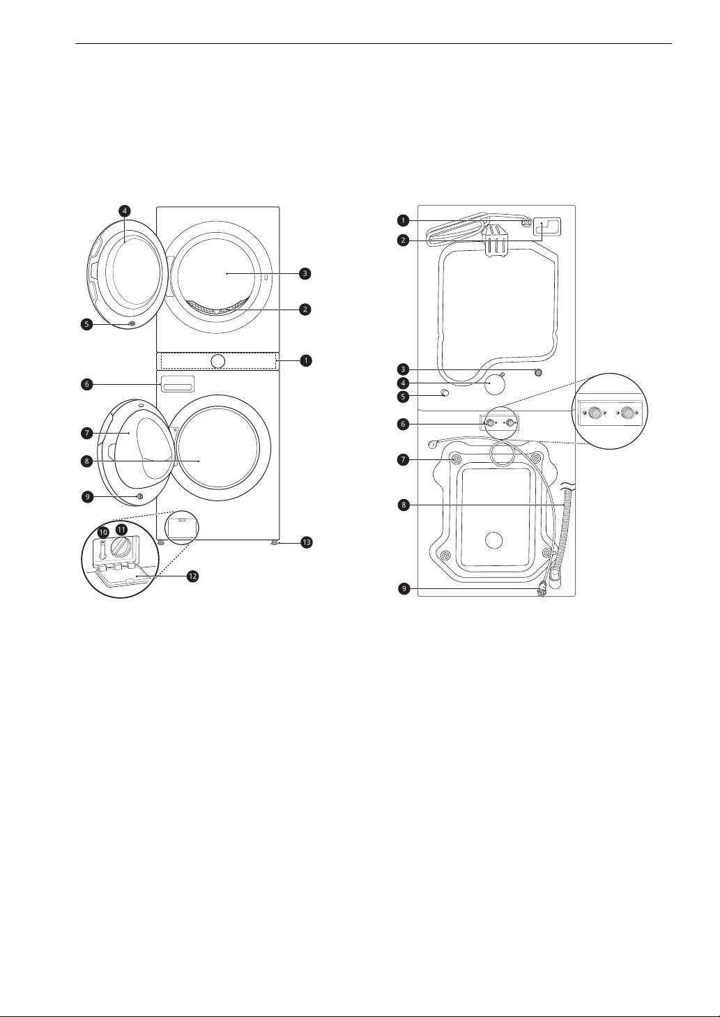
Front View
Rear View
a Control Panel
b Lint Filter
c Dryer Drum
d Dryer Door
e Dryer Door Magnet
f Detergent Dispenser Drawer
g Washer Door
h Washer Drum
i Washer Door Magnet
j Drain Hose
k Drain Pump Filter
l Drain Pump Filter Cover
m Leveling Feet
a Power Cord (for Gas Models)
b Terminal Block Access Panel (for Electric
Models)
c Cold Water Inlet
d Exhaust Duct Outlet
e Gas connection (for Gas Models)
f Hot and Cold Water Inlets
g Shipping Bolts
h Drain Hose
i Power Cord (for Washer)
Product Specifications
WARNING
9PRODUCT OVERVIEW
Model
Electrical Requirements
Min. / Max. Water Pressure 20 - 120 psi (138 - 827 kPa)
Dimensions (Width X Height X Depth) 27'' X 74 3/8'' X 30 3/8'' (70 cm X 189 cm X 77 cm)
Maximum Depth with Door Open 55'' (139.6 cm)
Net Weight 320 lb (145 kg)
Capacity (Washer/Dryer) 4.5 cu.ft. / 7.4 cu.ft.
Max. Spin Speed (Washer) 1300 RPM
Gas Requirements
Operating Temperature Range 41-95 ℉ (5-35 ℃)
I
G
S
N
E
D
C
E
R
D
E
I
T
I
F
WKEX200H*A / WKGX201H*A / WSEX200HNA /
WSGX201HNA
Please refer to the rating label for detailed
information.
NG: 4 - 10.5-inch (10.2 - 26.7 cm) WC
LP: 8 - 13-inch (20.4 - 33.1 cm) WC
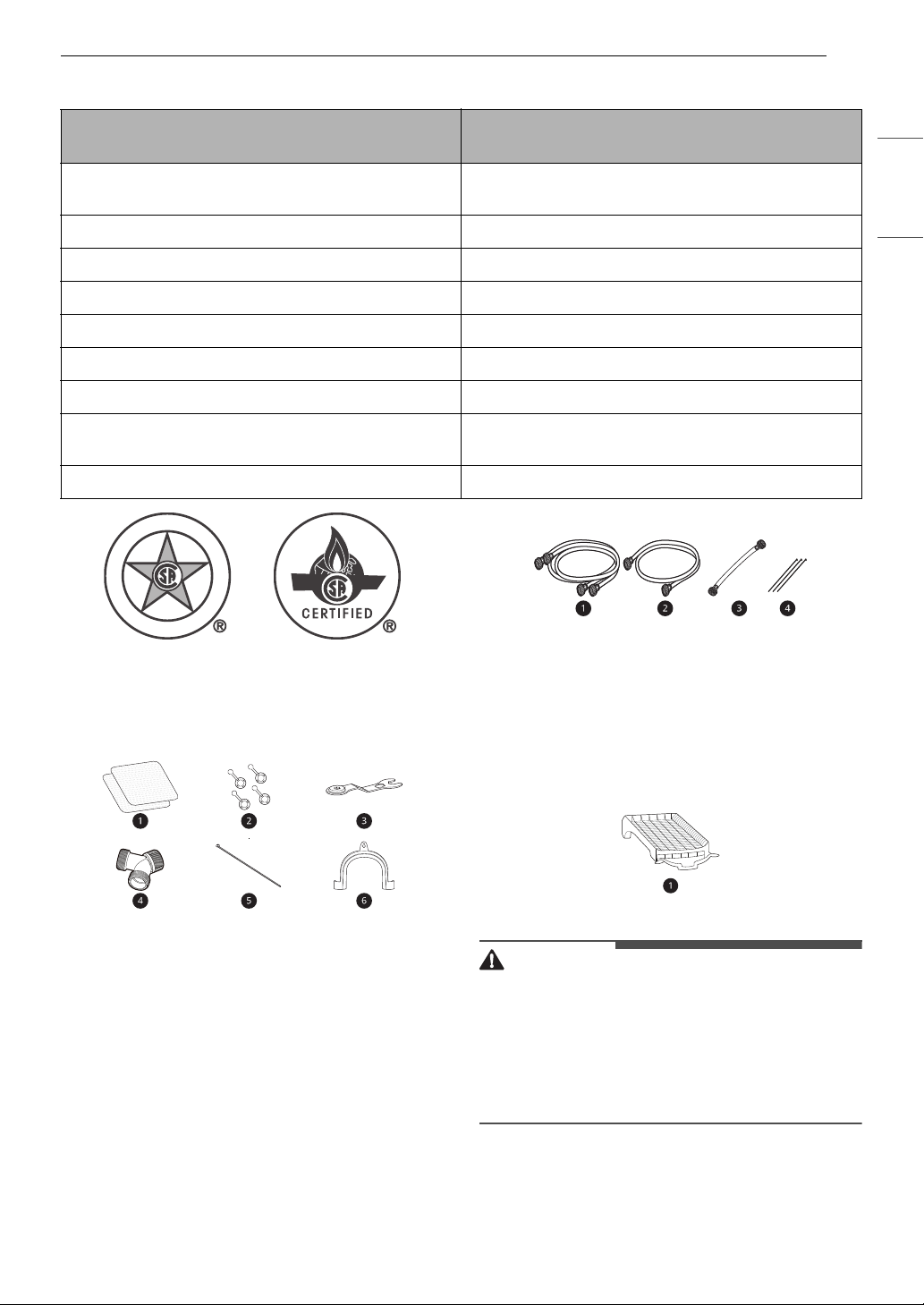
Required Accessories
a Hot and Cold Water Hoses (for Washer)
ENGLISH
Accessories
Included Accessories
a Non-skid Pads
b Hole Caps
c Wrench
d Y Connector
e Tie Strap
f Elbow Bracket (for securing drain hose)
b Cold Water Hose (for Dryer)
c Connecting Supply Hose
d Tie Straps
Optional Accessories
a Drying Rack
• For your safety and for extended product life,
use only authorized components. The
manufacturer is not responsible for product
malfunction, property damage or bodily injury
caused by the use of separately purchased
unauthorized components, parts, or non-LG
products.
10 INSTALLATION
INSTALLATION
Before Installing
Installation Overview
Please read the following installation instructions first after purchasing this appliance or transporting it to
another location.
a Choosing the Proper Location
b Unpacking and Removing Shipping Material
c Connecting the Electric Dryer
d Connecting the Gas Dryer
e Venting the Dryer
f Connecting the Inlet Hoses
g Connecting the Drain Hose
h Leveling the Appliance
i Final Installation Check
11INSTALLATION
WARNING
E
• Read all installation instructions completely before installing and operating the appliance. It is important
that you review this entire manual before installing and using the appliance. Detailed instructions
concerning electrical connections and additional requirements are provided on the following pages.
• Moving or installation of the appliance requires two or more people. Failure to follow these instructions
may result in injury.
• Store and install the appliance where it will not be exposed to temperatures below freezing or exposed
to outdoor weather conditions. Failure to follow this warning can cause product or part failure, serious
injury, fire, electric shock, or death.
• Properly ground the appliance to conform with all governing codes and ordinances. Failure to follow this
warning can cause serious injury, fire, electric shock, or death.
• To ensure proper airflow, do not block the large opening on the bottom of the appliance with carpeting
or other materials.
• Do not remove the ground prong from the power cord. Do not use an adapter or extension cord. Plug
into a grounded 3-prong outlet. Failure to follow this warning can cause serious injury, fire, electric
shock, or death.
• Certain internal parts are intentionally not grounded and may present a risk of electric shock only during
servicing. Service personnel- Do not contact the following parts while the appliance is energized: pump,
valve, motor, control board.
ENGLISH
Choosing the Proper
Location
Check the following requirements for the install
location before installing the appliance.
• Allow for sufficient space between the walls and
the appliance for installation.
• Make sure that the floor is clean, dry and free of
dust, dirt, water and oil so the leveling feet
cannot slide easily. Leveling feet that can move
or slide on the floor can contribute to excess
vibration and noise.
• If the floor has too much flex, reinforce it to
make it more rigid. If the floor is not solid, it may
cause severe vibration and noise.
• If a drain pan must be used, take extra care to
follow the instructions provided with the drain
pan and make sure the leveling feet are adjusted
for firm and even contact with the pan. Use of
drain pans and failure to properly level the
appliance may result in increased vibration and
noise during operation.
Flooring
• To minimize noise and vibration, install the
washer on a level, solidly constructed floor
capable of supporting the appliance without
flexing or bouncing.
• The appliance must be installed on firm flooring
to minimize vibration during the spin cycle.
Concrete flooring is best, but a wood floor is
sufficient, provided it is built to FHA standards.
• The floor under the appliance must not slope
more than 1 inch (2.5 cm) from front to back or
side to side.
• Installing on carpeting and soft tile surfaces is
not recommended.
• Never install the appliance on a platform or
weakly supported structure.
Floor Installation
To ensure sufficient clearance for water inlet
hoses, drain hose and airflow, allow minimum
clearances of at least 1'' (2.5 cm) at the sides and
4'' (10 cm) behind the appliance. Be sure to allow
for wall, door, or floor moldings that may increase
the required clearances.
12 INSTALLATION
NOTE
NOTE
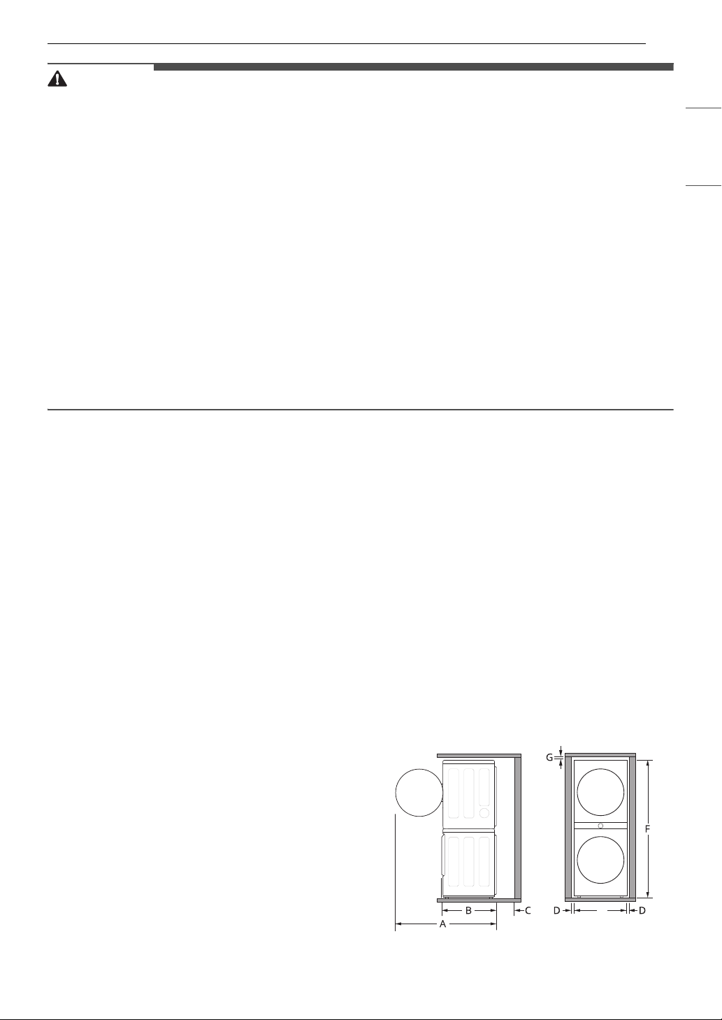
Dimensions and Clearances
A 55'' (139.6 cm)
B 30 3/8'' (77 cm)
C 4'' (10 cm)
D1'' (2.5 cm)
E 27'' (70 cm)
F 74 3/8'' (189 cm)
G1/4'' (0.5 cm)
Exhaust
• A location that allows for proper exhaust
installation. A gas dryer must be exhausted to
the outdoors.
Power Outlet
• The power outlet must be within 60 inches (1.5
m) of either side of the appliance.
• Position the appliance so that the outlet and
plug are easily accessible.
• Do not overload the outlet with more than one
appliance.
• The outlet must be grounded in accordance with
current electrical wiring codes and regulations.
• Use a time-delay fuse or circuit breaker.
• It is the personal responsibility and obligation of
the appliance owner to have a proper outlet
installed by a qualified electrician.
• Check code requirements that limit, or do not
permit, installation of the appliance in garages
or sleeping quarters. Contact your local building
inspector.
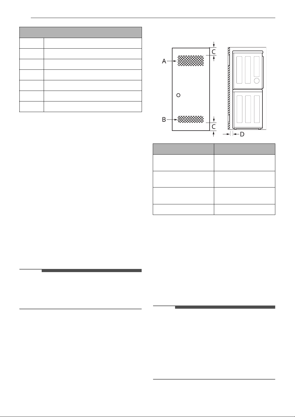
Installation spacing for Recessed Area
or Closet Installation
Description Dimension/Clearance
A: Upper Ventilation
Opening
B: Lower Ventilation
Opening
C: Distance to
Ventilation Opening
D: Front Clearance 4″ (100 mm)
48 sq. in. (310 cm
24 sq. in. (155 cm
3″ (76 mm)
Closet Ventilation Requirements
Closets with doors must have both an upper and
lower vent to prevent heat and moisture buildup in
the closet. One upper vent opening with a
minimum opening of 48 sq. in. (310 cm
installed no lower than 6 feet above the floor. One
lower vent opening with a minimum opening of 24
sq. in. (155 cm
one foot above the floor. Install vent grills in the
door or cut down the door at the top and bottom
to form openings. Louvered doors with equivalent
ventilation openings are also acceptable.
2
) must be installed no more than
2
)
2
)
2
) must be
Clearances
The following clearances are recommended for
the appliance.
• Additional clearances should be considered for
ease of installation and servicing.
• Additional clearances should be considered on
all sides of the appliance to reduce noise
transfer.
• There should be at least a little space around the
appliance (or any other appliance) to eliminate
the transfer of vibration from one appliance to
another. If there is enough vibration, it could
cause appliances to make noise or come into
contact, causing paint damage and further
increasing noise.
• No other fuel-burning appliance can be installed
in the same closet as an appliance.
Unpacking and Removing
CAUTION
CAUTION
WARNING
Shipping Material
Unpacking Shipping Material
* This feature is only available on some models.
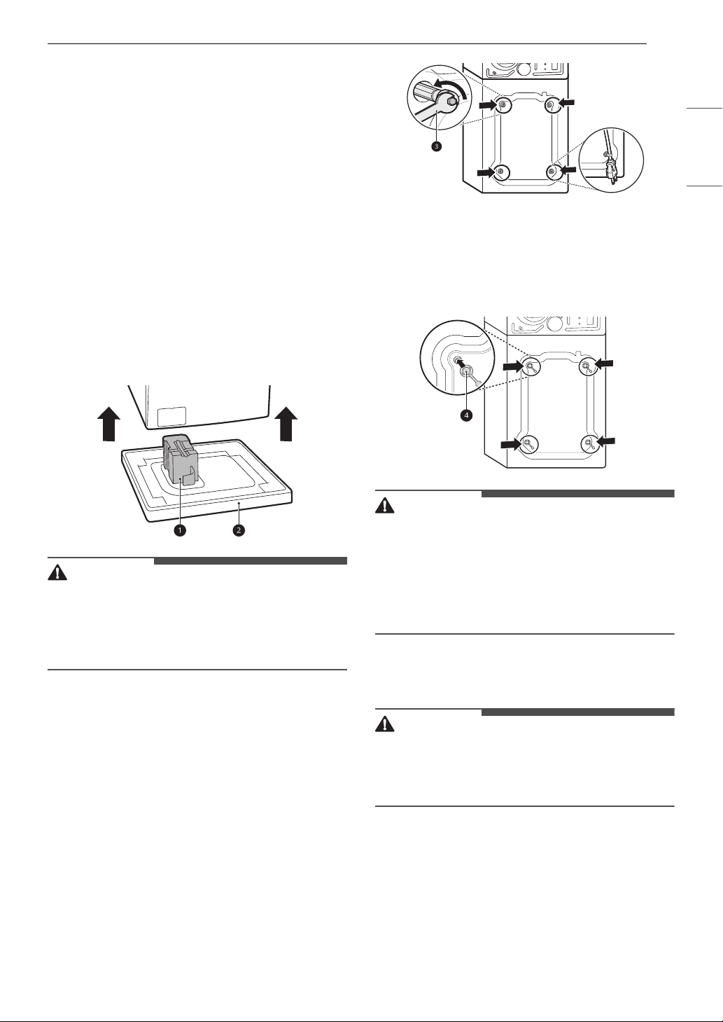
Lifting the Appliance off the Foam
Base
• After removing the carton and shipping
material, lift the appliance off the foam base.
• Make sure the plastic drum support
off with the base and is not stuck to the bottom
of the appliance.
• If you must lay the appliance down to remove
the carton base b, always protect the side of the
appliance and lay it carefully on its side. Do not
lay the appliance on its front or back.
a* comes
13INSTALLATION
ENGLISH
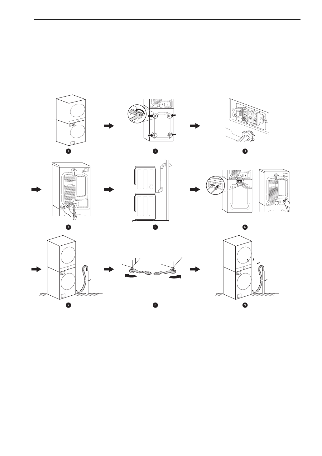
2 Install the hole caps.
• Locate the hole caps d included in the
accessory pack or attached to the back of
the washer. Install the caps in the holes left
by the bolt assemblies.
*
• Remove all shipping materials from the
appliance for proper operation and inspect it for
shipping damage. Failure to remove shipping
materials can cause excessive noise and
vibration.
Removing Shipping Material
1 Remove the bolt assemblies.
• Starting with the bottom two shipping bolts,
use the included wrench c to fully loosen
all 4 shipping bolts by turning them
counterclockwise.
• Remove the bolt assemblies (bolts and
retainers) by wiggling them slightly while
pulling them out.
• The power cord is secured to the back of the
washer with a shipping bolt to help prevent
operation with shipping bolts in place.
• Once removed, save the bolt assemblies for
future use. To prevent damage to internal
components, do not transport the appliance
without reinstalling the shipping bolts. Failure to
remove shipping bolts and retainers may cause
severe vibration and noise, which can lead to
permanent damage to the appliance.
Connecting Electric Dryers
• To reduce the risk of fire or explosion, electric
shock, property damage, injury to persons, or
death when using this appliance, fulfill the
following requirements.
Electrical Requirements for Electric
Models Only
14 INSTALLATION
WARNING
NOTE
• The wiring and grounding must conform to the
latest edition of the National Electrical Code,
ANSI/NFPA 70 and all applicable local
regulations. Please contact a qualified electrician
to check your home’s wiring and fuses to ensure
that your home has adequate electrical power to
operate the dryer.
• This dryer must be connected to a grounded
metal, permanent wiring system, or an
equipment-grounding conductor must be run
with the circuit conductors and connected to the
equipment-grounding terminal or lead on the
dryer.
• The dryer has its own terminal block that must
be connected to a separate 240 VAC, 60-Hertz,
single-phase circuit, fused at 30 amperes (the
circuit must be fused on both sides of the line).
ELECTRICAL SERVICE FOR THE DRYER SHOULD
BE OF THE MAXIMUM RATE VOLTAGE LISTED ON
THE NAMEPLATE. DO NOT CONNECT THE DRYER
TO 110-, 115-, OR 120-VOLT CIRCUIT.
• If the branch circuit to dryer is 15 ft. (4.5 m) or
less in length, use UL (Underwriters
Laboratories) listed No.-10 AWG wire (copper
wire only), or as required by local codes. If over
15 ft. (4.5 m), use UL-listed No.-8 AWG wire
(copper wire only), or as required by local codes.
Allow sufficient slack in wiring so the dryer can
be moved from its normal location when
necessary.
• The power cord (pigtail) connection between the
wall receptacle and the dryer terminal block IS
NOT supplied with the dryer. Type of pigtail and
gauge of wire must conform to local codes and
with instructions on the following pages.
• A 4-wire connection is required for all mobile
and manufactured home installations, as well as
all new construction after January 1, 1996. A 4wire connection must be used where local codes
do not permit grounding through the neutral
wire.
• Do not modify the plug and internal wire
provided with the dryer.
• The dryer should be connected to a 4-hole
outlet.
• If the plug does not fit the outlet, a proper outlet
will need to be installed by a qualified electrician.
• Connect the power cord to the terminal block.
Each colored wire should be connected to the
same color screw. Wire color indicated on
manual is connected to the same color screw in
the block.
• Grounding through the neutral conductor is
prohibited for: (1) new branch-circuit
installations, (2) mobile homes, (3) recreational
vehicles, and (4) areas where local codes prohibit
grounding through the neutral conductor.
• This dryer is supplied with the neutral wire
grounded. This white ground wire MUST BE
MOVED to the neutral terminal when a 4-wire
cord is to be used, or where grounding through
the neutral conductor is prohibited.
• For electrical requirements for mobile or
manufactured homes, see For Mobile or
Manufactured Homes.
Four-Wire Power Cord
• A 4-wire connection is required
for all mobile and manufactured
home installations, as well as all
new construction after January 1,
1996.
• A UL-listed strain relief is required.
• Use a 30-amp, 240-volt, 4-wire, UL-listed
power cord with #10 AWG-minimum copper
conductor and closed loop or forked terminals
with upturned ends.
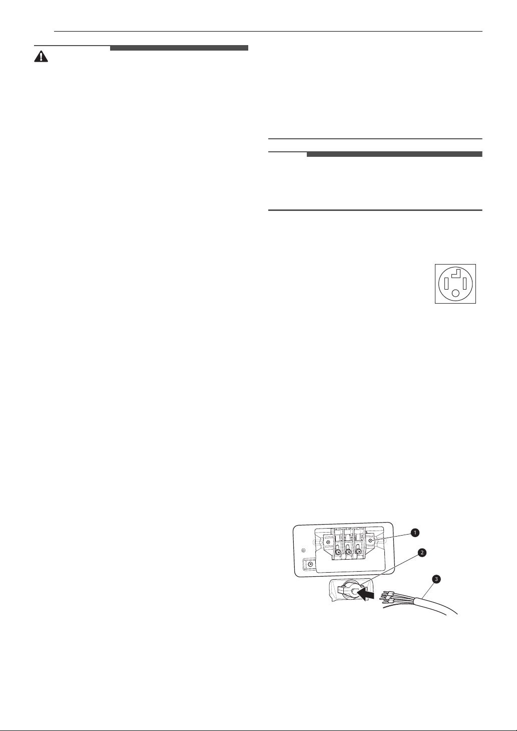
1 Remove the terminal block access cover on
the upper back of the appliance.
2 Install UL-listed strain relief into the power
cord through-hole.
3 Thread a 30-amp, 240-volt, 4-wire, UL-listed
power cord with #10 AWG-minimum copper
conductor through the strain relief.
a Terminal Block
b UL-Listed Strain Relief
c UL-Listed 4-Wire Power Cord
15INSTALLATION
a
b
b
c
d
e
5’’ (12.7 cm)
1’’ (2.5 cm)
a
a
b
c
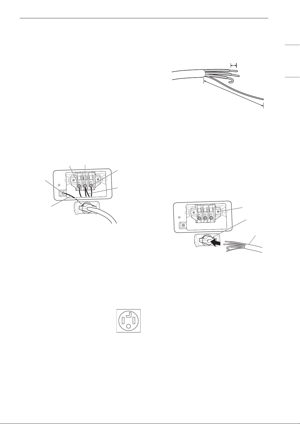
4 Transfer the appliance's ground wire from
behind the green ground screw to the center
screw of the terminal block.
5 Attach the two hot leads (black and red) of the
power cord to the outer terminal block
screws.
6 Attach the neutral (white) wire to the center
screw of the terminal block
7 Attach the power cord ground wire to the
green ground screw.
8 Tighten all screws securely.
9 Reinstall the terminal block access cover.
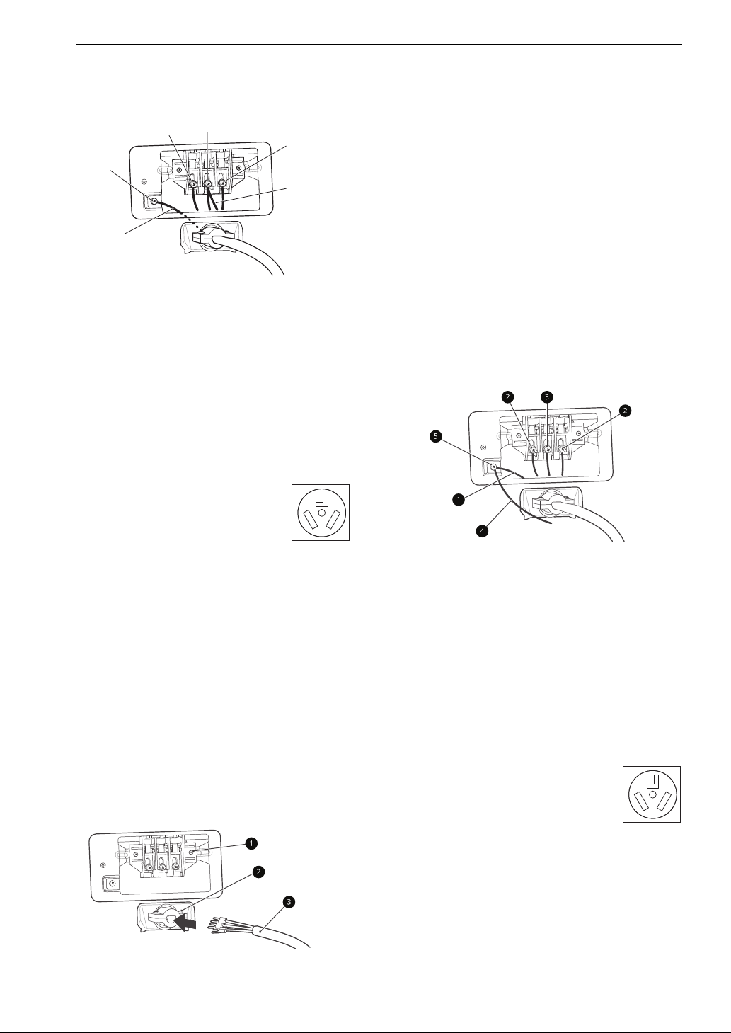
of insulation from the ground wire. Cut off
approximately 1.5 inches (3.8 cm) from the
other three wires and strip 1 inch (2.5 cm)
insulation from each wire. Bend the ends of
the three shorter wires into a hook shape.
a Ground Wire
2 Remove the terminal block access cover on
the upper back of the appliance.
3 Install UL-listed strain relief into the power
cord through-hole.
4 Thread the 4-wire #10 AWG minimum copper
power cable prepared in step 1 through the
strain relief.
ENGLISH
a White Wire moved from Ground Screw
b Hot Leads of Power Cord (Black and Red)
c Neutral Wire (White)
d Power Cord Ground Wire
e Ground Screw
Four-Wire Direct Wire
• A 4-wire connection is required
for all mobile and manufactured
home installations, as well as all
new construction after January 1,
1996.
• A UL-listed strain relief is required.
• Use UL-listed 4-wire #10 AWG minimum
1 Remove 5 inches (12.7 cm) of the outer
copper conductor cable. Allow at least 5 ft. (1.5
m) of wire to allow for removal and
reinstallation of the dryer.
covering from the wire and remove 5 inches
a Terminal Block
b UL-Listed Strain Relief
c UL-Listed 4-Wire Power Cord
5 Transfer the appliance's ground wire from
behind the green ground screw to the center
of the terminal block.
6 Attach the two hot leads (black and red) of the
power cord to the outer terminal block
screws.
7 Attach the neutral (white) wire to the center
screw of the terminal block.
8 Attach the power cord ground wire to the
green ground screw.
16 INSTALLATION
a
b
b
c
d
e
9 Tighten all screws securely.
10 Reinstall the terminal block access cover.
a White Wire moved from Ground Screw
b Hot Leads of Power Cord (Black and Red)
c Neutral Wire (White)
d Power Cord Ground Wire
e Ground Screw
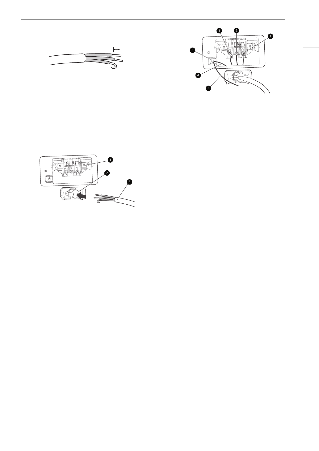
Three-Wire Power Cord
b UL-Listed Strain Relief
c UL-Listed 3-Wire Power Cord
4 Attach the two hot leads (black and red) of the
power cord to the outer terminal block
screws.
5 Attach the neutral (white) wire to the center
terminal block screw.
6 Connect the external ground (if required by
local codes) to the green ground screw.
7 Tighten all screws securely.
8 Reinstall the terminal block access cover.
• A 3-wire connection is NOT
permitted on new construction after
January 1, 1996.
• A UL-listed strain relief is required.
• Use a 30-amp, 240-volt, 3-wire, UL-listed
power cord with #10 AWG-minimum copper
conductor and closed loop or forked terminals
with upturned ends.
1 Remove the terminal block access cover on
the upper back of the appliance.
2 Install the UL-listed strain relief into the
power cord through-hole.
3 Thread a 30-amp, 240 volt, 3-wire, UL-listed
power cord with #10 AWG-minimum copper
conductor through the strain relief.
a Terminal Block
a White Wire from Dryer harness
b Hot Leads of Power Cord (Black and Red)
c Neutral Wire (White)
d External Ground Wire (If required by local
codes)
e Ground Screw
Three-Wire Direct Wire
• A 3-wire connection is NOT
permitted on new construction after
January 1, 1996.
• A UL-listed strain relief is required.
• Use UL-listed 3-wire, #10 AWG minimum
copper conductor cable. Allow at least 5 ft. (1.5
m) length to allow for removal and installation
of dryer.
1 Remove 3.5 inches (8.9 cm) of the outer
covering from the wire. Strip 1 inch (2.5 cm)
insulation from each wire. Bend the ends of
1’’ (2.5 cm)
the three wires into a hook shape.
2 Remove the terminal block access cover on
the upper back of the appliance.
3 Install UL-listed strain relief into the power
cord through-hole.
4 Thread the 3-wire, #10 AWG minimum copper
conductor power cable prepared in step 1
through the strain relief.
a Terminal block
b UL-listed strain relief
c UL-listed 3-wire power cord
5 Attach the two hot leads (black and red) of the
power cord to the outer terminal block
screws.
6 Attach the neutral (white) wire to the center
terminal block screw.
7 Connect the external ground (if required by
local codes) to the green ground screw.
8 Tighten all screws securely.
9 Reinstall the terminal block access cover.
17INSTALLATION
ENGLISH
a Hot lead (black and red)
b Neutral wire (white)
c External ground wire (if required by local
codes)
d Ground screw (green)
e Wire from the appliance harness
For Mobile or Manufactured Homes
• Any installation in a manufactured or mobile
home must comply with the Manufactured
Home Construction and Safety Standards Title
24 CFR, Part 3280 or Standard CAN/ CSA Z240
MH and local codes and ordinances. If you are
uncertain whether your proposed installation
will comply with these standards, please contact
a service and installation professional for
assistance.
• A 4-wire connection is required for all mobile
and manufactured home installations, as well as
all new construction after January 1, 1996.
• A gas dryer must be permanently attached to
the floor.
• The electrical connection for an electric dryer
must be a 4-wire connection. More detailed
information concerning the electrical connection
is provided in the section Connecting Electric
Dryers.
• To reduce the risk of combustion and fire, the
dryer must be vented to the outside.
• DO NOT vent the dryer under a manufactured
home or mobile home.
• Electric dryers may be vented to the outside
using the back, left, or right panel.
• Gas dryers may be vented to the outside using
the back or right panel. Gas dryers may not be
vented to the outside using the right side panel
because of the burner housing.
• The dryer exhaust duct must be affixed securely
to the manufactured or mobile home structure,
and the exhaust duct must be made of a
material that will resist fire and combustion. It is
18 INSTALLATION
WARNING
NOTE
WARNING
f
e
recommended that you use a rigid, semi-rigid or
flexible metal duct.
• DO NOT connect the dryer exhaust duct to any
other duct, vent, chimney, or other exhaust duct.
• Make sure the dryer has adequate access to
outside fresh air to ensure proper operation. The
opening for outside fresh air must be at least 25
sq. in (163 cm
• It is important that the clearance of the duct
from any combustible construction be at least 2
inches (5 cm), and when venting the dryer to the
outdoors, the dryer should be installed with a
clearance of at least 1 inch (2.5 cm) at the sides
and back of the dryer.
• Please be aware that venting materials are not
supplied with the dryer. You must obtain the
venting materials necessary for proper
installation.
2
).
Installing the Dryer Side
Vent Kit
The appliance is configured to vent to the rear. It
can also vent to the side.
• Use long-sleeved gloves and safety glasses.
• Use a heavy metal vent.
• Do not use plastic or thin foil ducts.
• Clean old ducts before installing the appliance.
• An adapter kit, part number 383EEL9001B, may
be purchased from your LG retailer. This kit
contains duct components necessary to change
the appliance vent location.
• Right-side venting is not available on gas
models.
• Bottom venting is not available on stacked or
integrated stacked models.
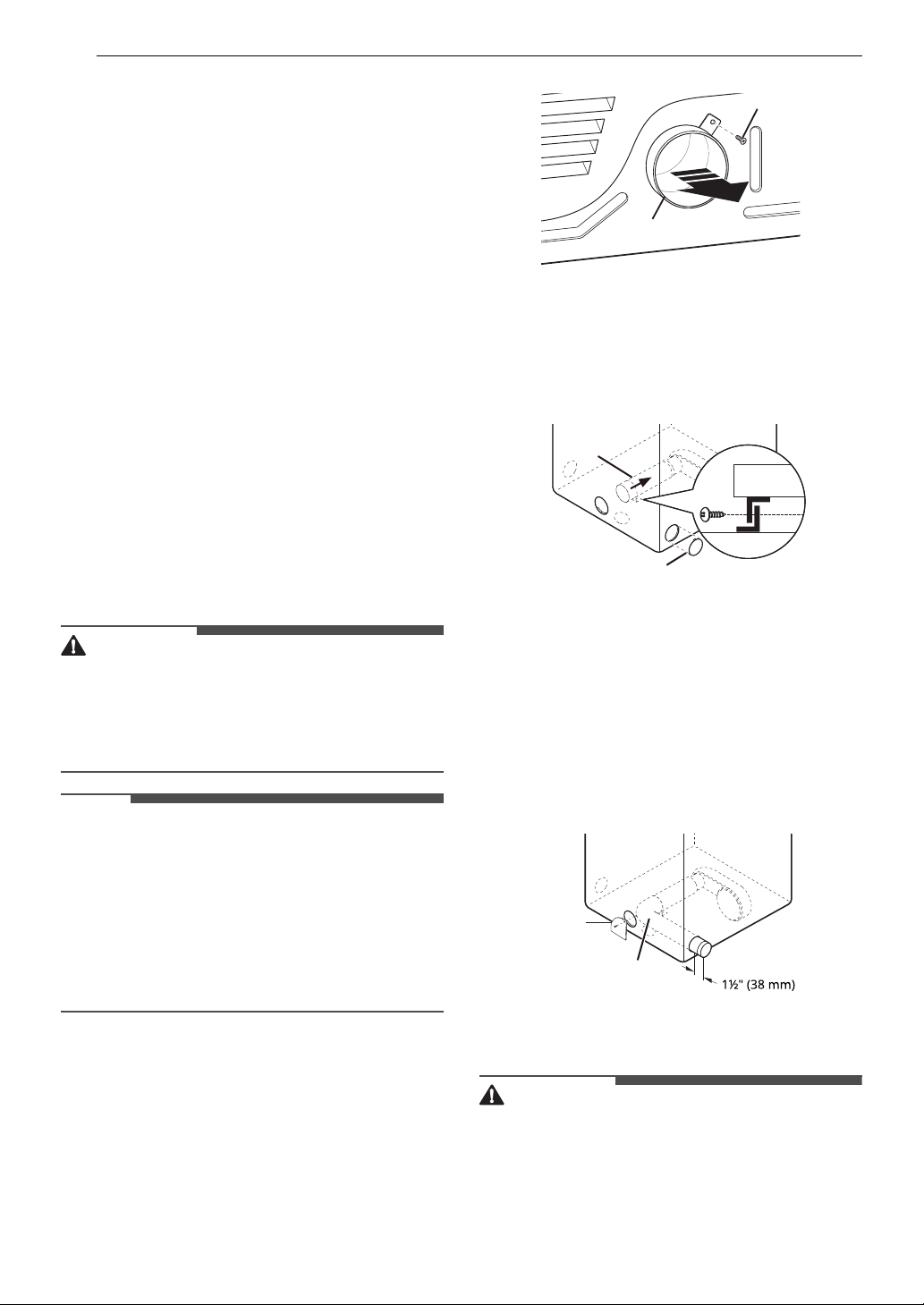
a
b
2 Press the tabs on the knockout c and
carefully remove the knockout for the desired
vent opening. (Right-side venting is not
available on gas models.) Press the adapter
d onto the blower housing and secure
duct
to the base of the dryer as shown.
d
c
3 Preassemble a 4" (10 cm) elbow e to the next
4" (10 cm) duct section, and secure all joints
with duct tape. Be sure that the male end of
the elbow faces AWAY from the dryer. Insert
the elbow/duct assembly through the side
opening and press it onto the adapter duct.
Secure it in place with duct tape. Be sure that
the male end of the duct protrudes 1 1/2" (3.8
cm) to connect the remaining ductwork.
Attach the cover plate
dryer with the included screw.
f to the back of the
Side Venting
1 Remove the rear exhust duct retaining screw
a and pull out the exhaust duct b.
Venting the Dryer
• Gas dryers MUST exhaust to the outdoors.
• DO NOT use sheet metal screws or other
fasteners which extend into the duct that could
catch lint and reduce the efficiency of the
exhaust system. Secure all joints with duct tape.
19INSTALLATION
NOTE
a
a
a: 4 ‘’ (10 cm)
b: 2 1/2 ‘’ (6.4 cm)
b
• To reduce the risk of fire, combustion, or
accumulation of combustible gases, DO NOT
exhaust dryer air into an enclosed and
unventilated area, such as an attic, wall, ceiling,
crawl space, chimney, gas vent, or concealed
space of a building.
• To reduce the risk of fire, DO NOT exhaust the
dryer with plastic or thin foil ducting.
• Do not exceed the recommended duct length
limitations noted in the chart. Failure to follow
these instructions may result in extended drying
times, fire or death.
• Do not crush or collapse ductwork.
• Do not allow ductwork to rest on or contact
sharp objects.
• If connecting to existing ductwork, make sure it
is suitable and clean before installing the dryer.
• Venting must conform to local building codes.
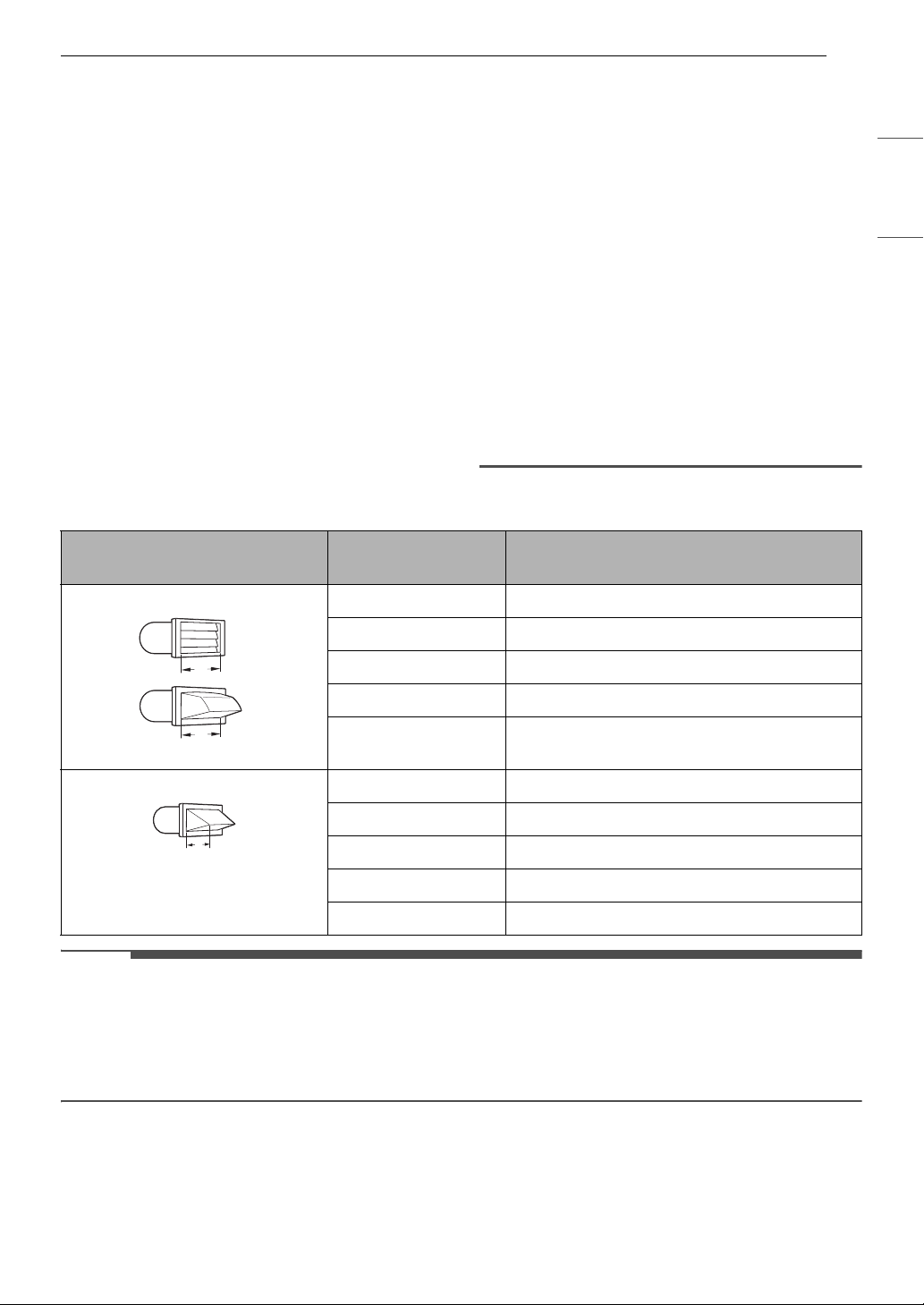
Ductwork
Wall Cap Type
Recommended 0 65 ft. (19.8 m)
Number of 90°
Elbows
• Use only 4 '' (10 cm) rigid, semi-rigid or flexible
metal ductwork inside the dryer cabinet and for
venting outside.
• The exhaust duct must be 4 '' (10 cm) in diameter
with no obstructions. The exhaust duct should
be kept as short as possible. Make sure to clean
any old ducts before installing your new dryer.
• Rigid, semi-rigid or flexible metal ducting is
recommended for use between the dryer and
the wall. All non-rigid metal transition duct must
be UL-listed. Use of other materials for transition
duct could affect drying time.
• Ductwork is not provided with the dryer. You
should obtain the necessary ductwork locally.
The vent hood should have hinged dampers to
prevent backdraft when the dryer is not in use.
• The total length of flexible metal duct must not
exceed 8 ft. (2.4 m).
Maximum length of 4-inch diameter rigid
metal duct
ENGLISH
1 55 ft. (16.8 m)
2 47 ft. (14.3 m)
3 36 ft. (11.0 m)
4 28 ft. (8.5 m)
Use for only short run installations 0 55 ft. (16.8 m)
1 47 ft. (14.3 m)
2 41 ft. (12.5 m)
3 30 ft. (9.1 m)
4 22 ft. (6.7 m)
• Deduct 6 ft. (1.8 m) for each additional elbow. Do not use more than four 90° elbows.
• In Canada, only those foil-type flexible ducts, if any, specifically identified for use with the appliance by
the manufacturer should be used. In the United States, only those foil-type flexible ducts, if any,
specifically identified for use with the appliance by the manufacturer and that comply with the Outline
for Clothes Dryer Transition Duct, Subject 2158A, should be used.
Routing and Connecting Ductwork
Follow the guidelines below to maximize drying
performance and reduce lint buildup and
condensation in the ductwork. Ductwork and
fittings are NOT included and must be purchased
separately.
• Use 4'' (10 cm) diameter rigid, semi-rigid or
flexible metal ductwork.
20 INSTALLATION
WARNING
WARNING
WARNING
• The exhaust duct run should be as short as
possible.
• Use as few elbow joints as possible.
• The male end of each section of exhaust duct
must point away from the dryer.
• Use duct tape on all duct joints.
• Insulate ductwork that runs through unheated
areas in order to reduce condensation and lint
buildup on duct surfaces.
• Incorrect or inadequate exhaust systems are not
covered by the dryer warranty. Dryer failures or
service required because of such exhaust
systems will not be covered by the dryer
warranty.
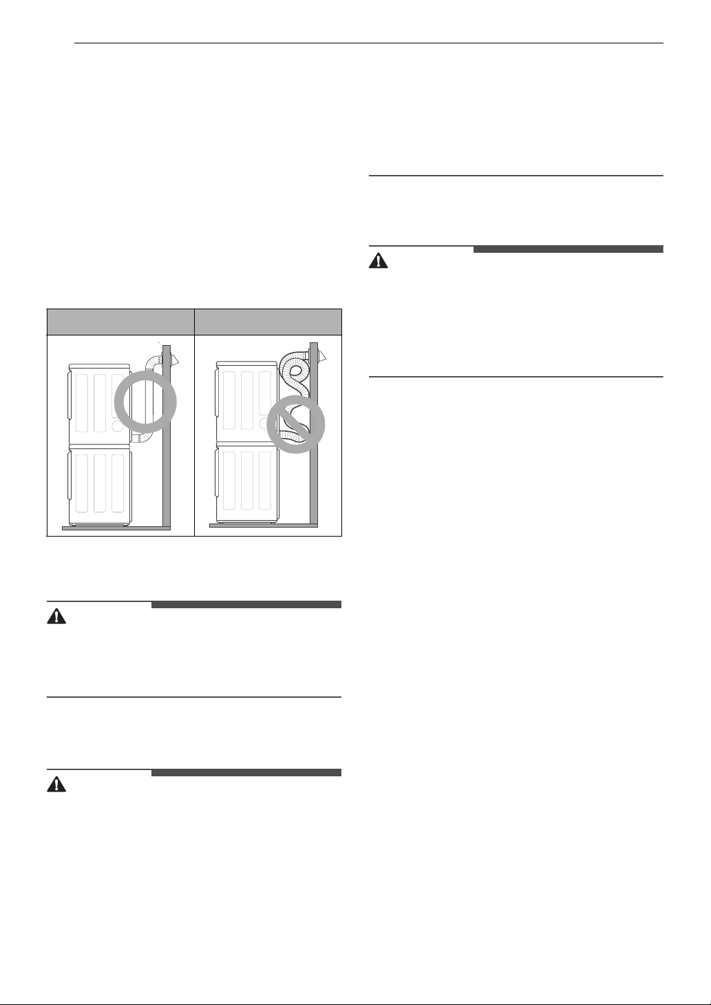
Correct Venting Incorrect Venting
Connecting Gas Dryers
• To reduce the risk of fire or explosion, electric
shock, property damage, injury to persons, or
death when using this appliance, follow
requirements including the following:
Electrical Requirments for Gas
Models
• This dryer is equipped with a three-prong
grounding plug for protection against shock
hazard and should be plugged directly into a
properly grounded three-prong receptacle. Do
not cut or remove the grounding prong from
this plug.
• Do not, under any circumstances, cut or remove
the third (ground) prong from the power cord.
• For personal safety, this dryer must be properly
grounded.
• This dryer must be plugged into a 120-VAC, 60Hz. grounded outlet protected by a 15-ampere
fuse or circuit breaker.
• Where a standard 2-prong wall outlet is
encountered, it is your personal responsibility
and obligation to have it replaced with a
properly grounded 3-prong wall outlet.
Gas Supply Requirements
• DO NOT attempt any disassembly of the dryer;
disassembly requires the attention and tools of
an authorized and qualified service technician or
company.
• DO NOT use an open flame to inspect for gas
leaks. Use a noncorrosive leak detection fluid.
• Gas pressure must not exceed 8-inch (20.4 cm)
water column for NG, or 13-inch (33.1 cm) water
column for LP.
• Isolate the dryer from the gas supply system by
closing its individual manual shutoff valve during
any pressure testing of the gas supply.
• Supply line requirements: Your laundry room
must have a rigid gas supply line to your dryer.
In the United States, an individual manual
shutoff valve MUST be installed within at least 6
ft. (1.8 m) of the dryer, in accordance with the
National Fuel Gas Code ANSI Z223.1 or Canadian
gas installation code CSA B149.1. A 1/8-inch NPT
pipe plug must be installed.
• If using a rigid pipe, the rigid pipe should be 0.5inch IPS. If acceptable under local codes and
ordinances and when acceptable to your gas
supplier, 3/8-inch approved tubing may be used
where lengths are less than 20 ft. (6.1 m). Larger
tubing should be used for lengths in excess of 20
ft. (6.1 m).
• To prevent contamination of the gas valve,
purge the gas supply of air and sediment before
connecting the gas supply to the dryer. Before
tightening the connection between the gas
supply and the dryer, purge remaining air until
the odor of gas is detected.
• Use only a new AGA- or CSA-certified gas supply
line with flexible stainless steel connectors.
• Use Teflon tape or a pipe-joint compound that is
insoluble in propane (LP) gas on all pipe threads.
 Loading...