

Page 1

WASHING MACHINE
SERVICE MANUAL
READ THIS MANUAL CAREFULLY TO DIAGNOSE TROUBLES
CORRECTLY BEFORE OFFERING SERVICE.
MODEL : WD-1247(0~9)BD(M)
CAUTION
Page 2

MAY. 2006 PRINTED IN KOREA
P/No.:3828ER3048Y
Page 3

CONTENTS
1. SPECIFICATION............................................................................................................................3
2. FEATURES & TECHNICAL EXPLANATION ................................................................................ 4
3. PARTS IDENTIFICATION ............................................................................................................ 7
4. INSTALLATION ............................................................................................................................. 8
5. WIRING DIAGRAM / PROGRAM CHART ...................................................................................11
6. OPERATION ................................................................................................................................12
7. TROUBLE SHOOTING................................................................................................................14
7-1.BEFORE SVC CHECKING ..................................................................................................14
7-2.QC TEST MODE..................................................................................................................14
7-3.HOW TO KNOW THE WATER LEVEL FREQUENCY.........................................................14
7-4.ERROR DISPLAY ................................................................................................................15
8. ERROR DIAGNOSIS AND CHECK LIST ....................................................................................17
8-1. DIAGNOSIS AND ANSWER FOR ABNORMAL OPERATION ...........................................17
8-2. FAULT DIAGNOSIS AND TROUBLE SHOOTING .............................................................20
9. DISASSEMBLY INSTRUCTIONS ...............................................................................................30
10. EXPLODED VIEW AND PARTS LIST .......................................................................................40
10-1. THE EXPLODED VIEW OF CABINET ASSEMBLY .........................................................40
10-2. THE EXPLODED VIEW OF DRUM AND TUB ASSEMBLY .............................................41
10-3. THE EXPLODED VIEW OF CONTROL PANEL AND DISPENSER ASSEMBLY ............42
2
Page 4
3
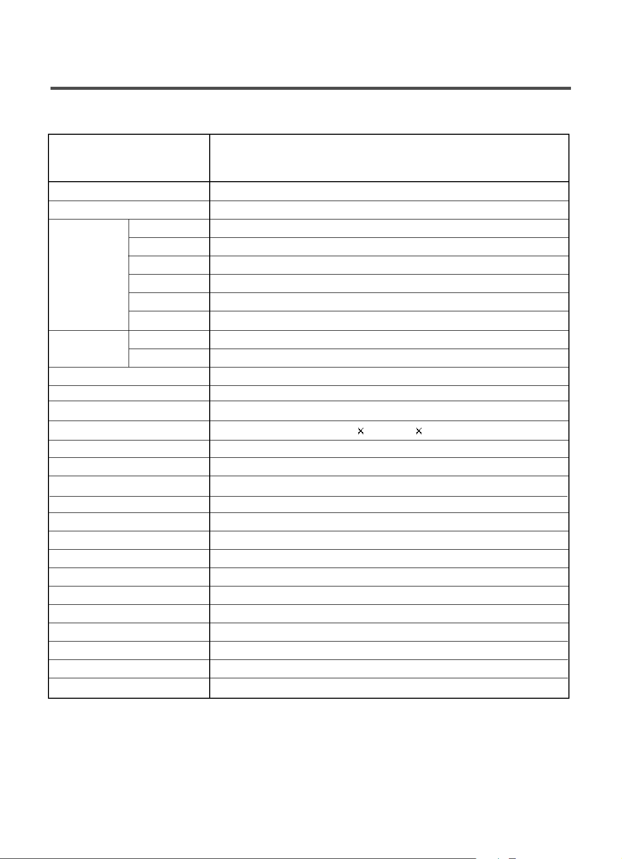
1. SPECIFICATION
ITEM
PO
WER SUPPLY
PRODUCT WEIGHT
WASHING 200W
SPIN 300W
FAN MOTOR 25W
DRAIN MOTOR 35W
WASH HEATER
STEAM HEATER
WASH 46rpm
No Spin/400/600/800/1000/1200
OPERATION WATER PRESSURE
0.3-10kgf/cm2(30-1000kPa)
CONTROL TYPE Electronic
WASH CAPACITY
DIMENSION 635mm(W)
720mm(D) 925mm(H)
WASH PROGRAM
RINSE Normal, Rinse+, Medic Rinse, Rinse Hold
DOOR SWITCH TYPE PTC+Solenoid Type
WATER LEVEL 10 steps (by sensor)
RESERVATION From 3 hours to 19 hours
SENSING OF THE LAUNDRY AMOUNT
Adapted
FUZZY LOGIC Adapted
DISPLAY OF THE REMAINING TIME
Adapted
ERROR DIAGNOSIS 10 items
POWER AUTO OFF Adapted
CHILD LOCK Adapted
AUTO RESTART Adapted
TIME SAVE Adapted
TURBO STEAM Adapted
ELECTRICITY
CONSUMPTION
REVOLUTION
SPEED
WD-1247(0~9)BD(M)
SPIN
220V-240V~, 50Hz
81kg
2000W
9kg
Cotton, Synthetic, Delicate, Wool/Silk, Hand Wash, Duvet, Quick 30, Refresh, Baby Care
1100W
Page 5
2. FEATURES & TECHNICAL EXPLANATION
4
2-1.FEATURES
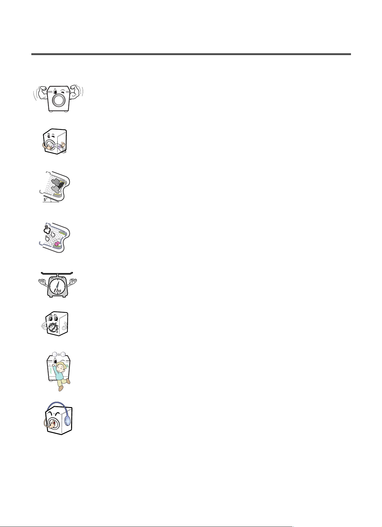
■
Ultra Capacity
The Larger drum enables not just higher head drop and stronger centrifugal
force, but also less tangling and wrinkling of the laundry. Heavier loads, such
as king size comforters, blankets, and curtains, can be washed.
■
Direct Drive System
The advanced Brushless DC motor directly drives the drum without
belt and pulley.
■
Tilted Drum and Extra Large Door Opening
Tilted drum and extra large opening make it possible to load
and unload clothing more easily.
■
Steam Washing and SteamFresh
TM
Steam Washing features upgraded washing performance with low energy
and water consumption. SteamFreshTMcycle removes wrinkles from dry
clothes.
■
Automatic Wash Load Detection
Automatically detects the load and optimizes the washing time.
■
Built-in Heater
Internal heater helps to maintain water temperature at its optimum level for
selected cycles.
■
Child Lock
The Child lock prevents children from pressing any button to change the
settings during operation.
■
Auto Leveling Leg
It is located at the right rear of the product and automatically adjusts the
leveling of the leg in order to reduce vibration and noise.
추가선택 예약
추가선택 예약
Page 6
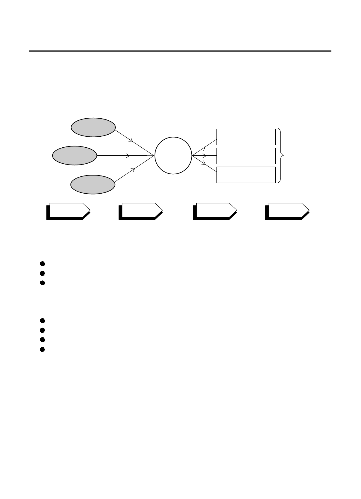
2-2.DETERMINE WASHING TIME BY FUZZY LOGIC
To get the best washing performance optimal time is determined by sensing of water temperature,
selected washing temperature and laundry amount.
2-3.WATER LEVEL CONTROL
This model adopts a pressure sensor which can sense the water level in the tub.
Water supply is stopped when the water level to the preset level, then washing program proceeds.
Spinning does not proceed until the water in the tub reduces to a certain level.
2-4. DOOR CONTROL
The door can be opened by pulling the door handle whenever washer is not in operation.
When the cycle is completed, the DOOR LOCKED light will turn off.
If a power failure has occurred while in operation, the door will unlock after 5 minutes.
Clicking sounds can be heard when the door is locked/unlocked.
5
FUZZY
LOGIC
laundry
amount
selected
washing
temperature
water
temperature
washing time
rinsing time
spin rhythm, time
the best
washing
performance
SENSING
PROCESSING
DETERMINATION
EFFECT
Page 7

6
2-5. THE DOOR CAN NOT BE OPENED
While program is operating
When a power failed and power plug is taken out in operation
While Door Lock lights turn on.
White the motor is in the process of intertial rotating, through the operation is paused.
2-6. DOOR LOCKED LAMP LIGHTS
When the frequency of water level is lower than 22.9 kHz
(It can be canceled when the frequency is more than 23.8 kHz)
When the temperature inside the tub is higher than 45 °C and water level is not 25.5 kHz
(It can be canceled when the water level is 25.5 kHz or the temperature inside the tub is lower than 40 °C)
2-7. CHILD LOCK
Use this option to prevent unwanted use of the washer. Press and hold the Wash and Rinse button for 3
seconds to lock/unlock control.
When Child lock is set, CHILD LOCK lights and all buttons are disabled except the Power button. You can
lock the washer while it is operating.
2-8. WATER CIRCULATION
When Washing and Rinsing function of shower at the upper part of Gasket.
When Washing, it continuously operates for 3 minutes and intermittently.
When Rinsing, it continuously operates after completion of water supply.
2-9. STEAM
For tough stained clothes, underwear, or baby clothes.
Steam Wash is available with Cotton, Synthetic, Baby Care and Refresh program.
This option features upgraded washing performance with low energy and water consumption
Do not load delicates such as wool, silk, and easily discolored clothes.
Page 8
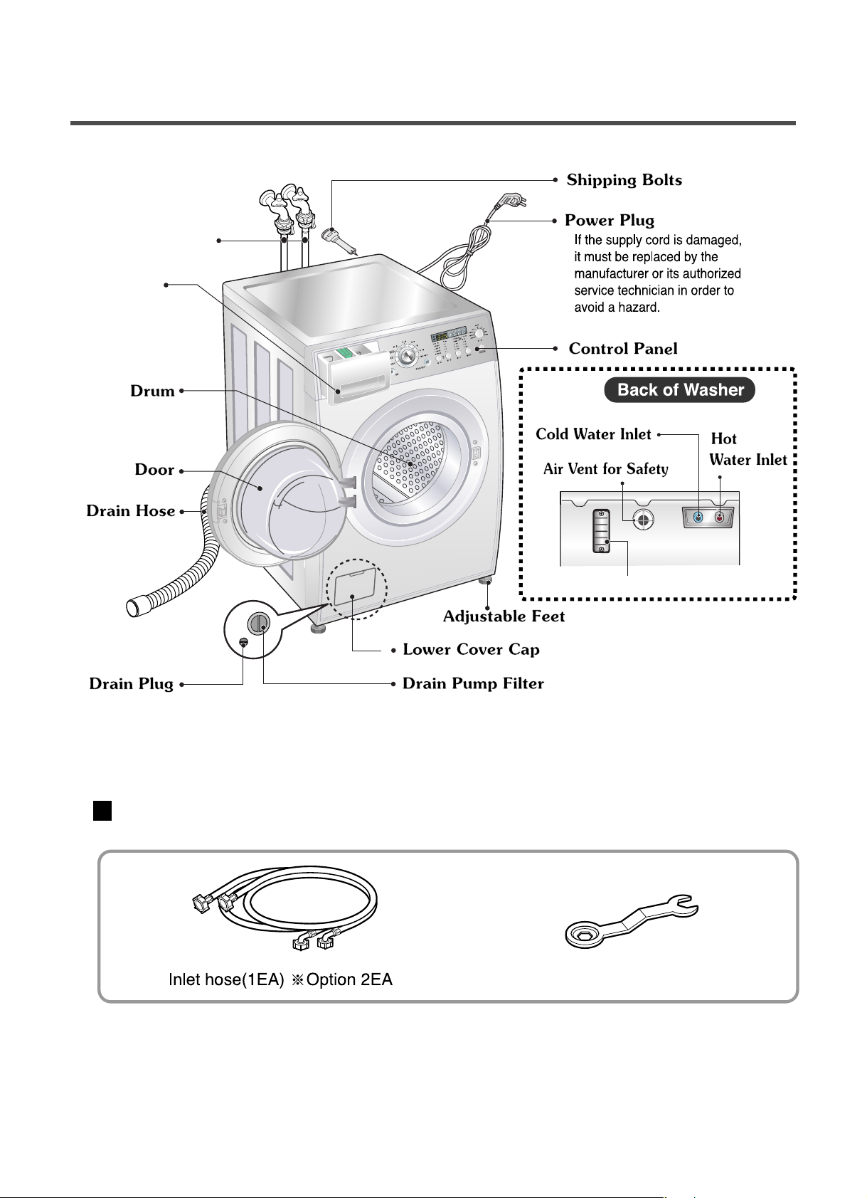
3. PARTS IDENTIFICATION
7
ACCESSORIES
Spanner
❋ Option : Safety Cover (PLC Modem)
Water Supply
Hose
Drawer
Page 9
Before servicing ask troubles of customers
Check the adjustment(power supply is 220-240V~, remove the transit bolts....)
Check the troubles referring to the trouble shooting.
Decide service steps referring to disassembly instructions.
And then, service and repair.
After servicing, operate the appliance whether it works O K or NOT.
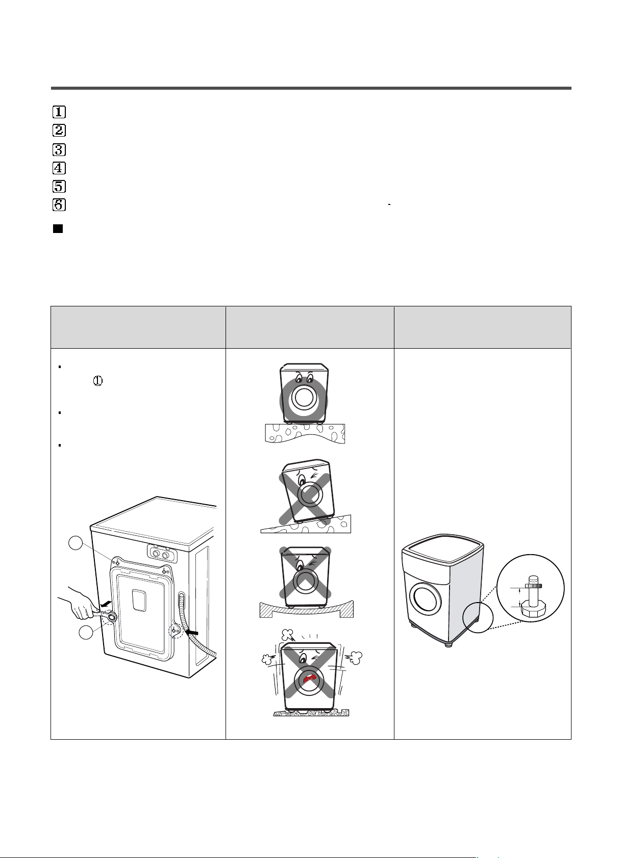
STANDARD INSTALLATION
The appliance should be installed as follows.
REMOVE THE TRANSIT INSTALL THE APPLIANCE ADJUST THE
BOLTS ON FLAT AND FIRM SURFACE HORIZONTAL
Remove the transit bolts
(4EA:
)with supplied spanner.
Keep the transit bolts and
spanner for future use.
Insert the 4 caps
provided into the hole
4. INSTALLATION
8
1
2
• Level the legs by using a spanner
provided.
(Turning clockwise to raise the
height of washing machine and
counterclockwise to lower.)
For your convenience, an auto
leveling leg of this product is
automatically adjusting the leveling
of the product to the some
degree(effective on 2~15cm titled
floor)
2~15mm
Page 10
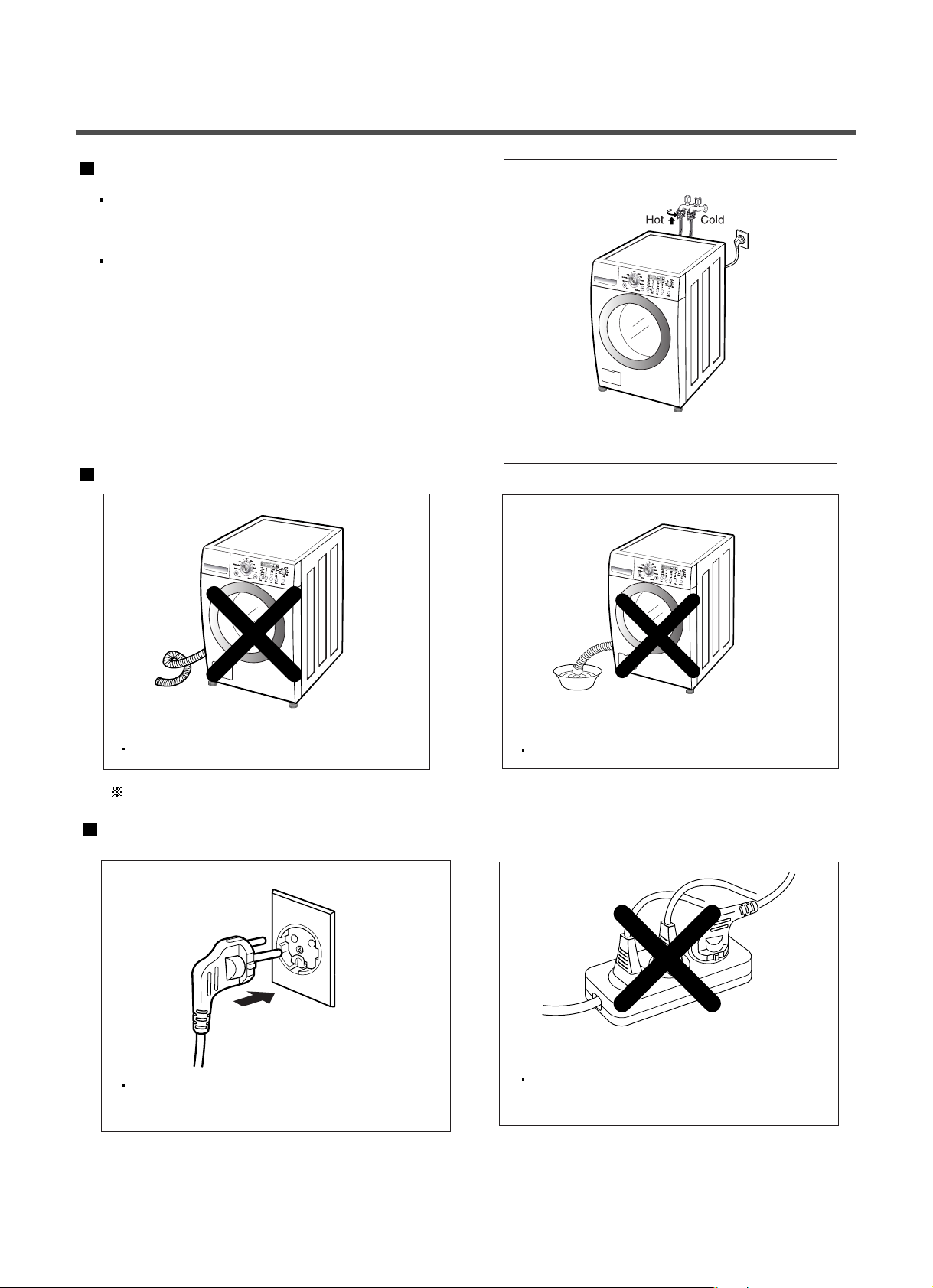
HOW TO CONNECT INLET HOSE
Check that the rubber packing is inside of the
valve connector.
Connect the inlet hose firmly to prevent leak.
CONNECT DRAIN HOSE
CONNECT POWER PLUG
9
Make sure that the hose is not twisted.
The drain hose should be placed under 100cm from the floor.
Connect the power plug to the wall outlet.
Avoid connecting several electric devices,
It may be the cause of the fire.
Avoid submerging the end of the hose.
F
avori
t
e
Sanitary
Sanitary
Favorite
Sanitary
Favo
ri
t
e
Page 11
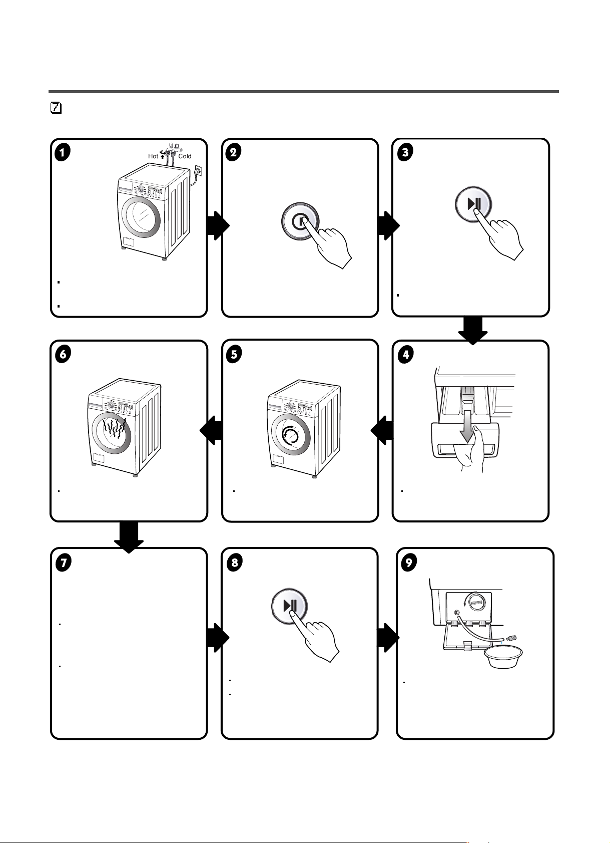
TEST OPERATION
10
MAX
max
Fav
o
rite
S
a
n
ita
r
y
F
a
vor
i
t
e
Sanitary
Favorite
Sanitary
Connect the power plug to
the outlet.
In case of Coloreds program.
Connect the inlet hose.
Preparation for Press the POWER button. Press
the
Start/Pause
washing. button.
Press the Temp. button Check if the drum rotates Check if water is supplied
and the present temperature will
clockwise and counterclockwise.
through the detergent dispenser.
be displayed.
Power off and then power on.
Check if the door can be
opened after 3 minutes.
Turn off Wash and Rinse after
pressing the Start/Pause button
and start the machine again.
Check drain and spin.
If SVC is needed during
check, remove
the remaining water by pulling
out the hose cap.
Check the water heating. Check automatic reverse Check the water supply.
turn.
Check drain and spin
Power off and open the
Water removal
door
Page 12
11
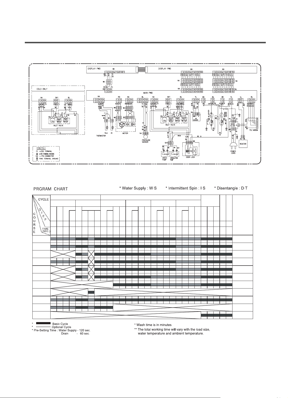
6. WIRING DIAGRAM / PROGRAM CHART
Drain
I
⁄
Heat
Steam
Wash
Drain
I
⁄
Drain
I
⁄
Drain
I
⁄
Drain
I
⁄
1234567891011121314151617181920212223242526272829
60 (”—) 60 180 120 (”—) 60 180 120 180 60 180 120 180 60 180 120 180 60 180 120 180 60 480 180 20 20
20
**Approx
Working
Time
(Minute)
28
19
155
68
72
62
72
30
E
N
D
A
U
T
O
O
F
116
88
Rinse
Spin
Drain
Spin
D
⁄
T
Extra &
Stain(4~6)
W
⁄
S
Rinse
3
W
⁄
S
Rinse
2
W
⁄
S
Rinse
Wash
1
W
⁄
S
Rinse
Wash
Pre Main
W
⁄
S
Wash
W
⁄
S
Baby Care
Wash
Spin
Duvet
Quick 30
Rinse+Spin
Refresh
Cotton
Synthetic
Delicate
Hand Wash
/Wool
S
812
812
8
8
812
42
42
12
42
S
S
S
S
Page 13

12
5. OPERATION
• Use this button to turn the power
On/Off.
• Rotate the Cycle selector knob to
select the cycle designed for different
types of fabric and soil levels.
POWER BUTTON
START/PAUSE BUTTON
WASH BUTTON
CYCLE SELECTOR KNOB EST. TIME REMAINING
• Pre Wash: Use this option for loads that need pretreatment. It add 16
minutes prewash and drain.
• Rinse+Spin: Use this option to rinse and then spin.
• Spin Only: When you want spin only, select this option.
• Less Steam: Use this option to a steam wash for only a small amount
of laundry, select the this option. Temperature fixed 30°C.
• Eco Steam: Use this option to a steam wash while reducing the
electricity consumption, select the option.
Temperature fixed 40°C.
• Use this button to Start/
Stop the washer.
• This display shows:
a) the estimated time remaining in the
cycle when operating.
b) an error code when an error has been
detected.
Page 14

• If the laundry is heavily soild “Intensive” option
is effective. By selecting the Intensive option,
the wash time may be extended, depending on
the program selected.
• Favorite:This option allows you to store a
customized wash cycle for future use.
13
CHILD LOCK RINSE, BEEPER, TEMP. BUTTON
SPIN SELECTOR KNOB
TIME DELAY
STATUS INDICATOR
TURBO STEAM
INTENSIVE, FAVORITE BUTTON
• Use this option to prevent unwanted use of the
washer. Press and hold the Wash and Rinse
button for 3 seconds to lock/unlock control.
• When Child lock is set, CHILD LOCK lights
and all buttons are disabled except the Power
button. You can lock the washer while it is
operating.
• To change the spin speed, turn
the Spin knob to cycle through
available options.
• This option features upgraded
washing performance with low
energy and water
consumption.
• Allows the start of any cycle
to be delayed for 3~19
hours.
• Select a water temperature based on the type of
load you are washing.
• Press repeatedly to adjust the volume of the Beeper.
• To change the Rinse Cycling, press the Rinse button
repeatedly through available options.
• These lights show which portion
of the cycle the washer is
operating.
Page 15

7-1.BEFORE SVC CHECKING
Be careful of electric shock or disconnecting the parts while trouble shooting.
Voltage of each terminal is 220-240V~ and DC while applying an electric current.
7-2.QC TEST MODE.
Pressing Rinse, and Spin button simultaneously.
Press the Power button, while the above condition.
Press the Start/Pause button as follows.
7-3.HOW TO KNOW THE WATER LEVEL FREQUENCY
Press the
Rinse and Spin button simultaneously.
ex) 241 : Water level frequency = 241 10-1kHz
=24.1 kHz
7-4.HOW TO KNOW TO TEMPERATURE OF EACH THERMISTOR
AT OPERATING CONDITION.
■ Thermistor in tub : Press the [Temp.] button.
■ Thermistor in dry duct : Press the [Turbo Steam] button.
14
7. TROUBLE SHOOTING
The digits means water level frequency(10-1kHz)
Number of times the
Start/Pause button is pressed
Check Point Display Status
None Turns on all lamps and locks the door.
1 time Tumble clockwise rpm (42~50)
2 times Low speed Spin. rpm (55~65)
3 times High speed Spin rpm (110~120)
4 times Inlet valve for prewash turns on. Water level frequency (25~65)
5 times Inlet valve for main wash turns on. Water level frequency (25~65)
6 times Inlet valve for hot water turns on. Water level frequency (25~65)
7 times Inlet valve for steam water turns on. Water level frequency (25~65)
8 times
Tumble counterclockwise
pm (42~50)
9 times
Wash heater turns on for 3 sec.
Water temperature
10 times
Circulation pump turns on.
Water level frequency (25~65)
11 times
Drain pump turns on.
Water level frequency (25~65)
12 times
Water level Sensor for Steam
Water level frequency of TSG (0~255)
13 times
Steam Heater turns on for 1,2 sec.
TSG temperature
14 times
Power off and unlock the door.
Turn off all lamps.
Page 16

15
7-5.ERROR DISPLAY.
If you press the Start/Pause button in error condition, any error except ‘ ’ will disappear and the
machine will change into pause status.
In case of if the error is not resolved within 20 sec., and in case of other errors,
if the error is not resolved within 4 min., power will be turned off automatically and the error only will be
blinked. But in case of
, power will not be turned off.
ERROR SYMPTOM CAUSE
1
2
3
4
5
6
7
• Not reached to the water level(246)within 8
minutes after water supplied or not reached to
the preset water level within 25 minutes.
• Not fully drained within 10 minutes.
• Water is over flowing(over 8 level).
※ If is displayed, drain pump operates to
drain water automatically.
• The sensor pressure switch is out of order.
• In case of operating the reservation function or
the other function with door opened. Close the
door, then the error display is resolved.
• The door switch is out of order.
• The appliance is tilted.
• Laundry is gatherd to one side.
• The THERMISTOR is out of order.
WATER INLET
ERROR
DRAIN ERROR
OVERFLOW
ERROR
SENSOR PRESSURE
S/W ERROR
DOOR OPEN
ERROR
IMBALANCE
ERROR
HEATING
ERROR
Page 17

ERROR SYMPTOM CAUSE
8
9
• MAIN PWB ASSEMBLY is out of order
Replace the MAIN PWB ASSEMBLY
• Winding in the STATOR ASSEMBLY is short-circuited.
Replace the STATOR ASSEMBLY
• “ ” is dispplayed during a high spin
Replace the LEAD WIRE ASSEMBLY (MOTOR)
• The connector in the LEAD WIRE ASSEMBLY is not connected to
the connnector of STATOR ASSEMBLY
Reconnect or repair the connector
• The hall sensor is out of order/defective.
Replace the STATOR ASSEMBLY
CURRENT
ERROR
MOTOR
ERROR
16
• Loose Ball Sensor Connector.
• Ball Sensor is out of order.
※ Displayed only when the START/PAUSE button is first
pressed in the QC Test Mode.
11
BALL
SENSOR
ERROR
•
The washer experienced a power failure.
• Restart the cycle.
13
POWER
FAILURE
• EEPROM is out of order.
※ Displayed only when the START/PAUSE button is first
pressed in the QC Test Mode.
12
EEPROM
ERROR
Page 18

17
8-1.DIAGNOSIS AND ANSWER FOR ABNORMAL OPERATION
8. ERROR DIAGNOSIS AND CHECK LIST
SYMPTOM GUIDE FOR SERVICE CALL
NO POWER
Water inlet trouble
Is the power plug connected firmly to
220-240V~ outlet?
Power failure? or Breaker opened?
Visit to check
Is " " displayed?
Is the tap opened?
Is the tap frozen?
Is the water supply shut-off?
Is filter in the inlet valve clogged with
foreign material?
Visit to check
Clean the filter of
inlet valve
Page 19

18
SYMPTOM
• Door does not open
• Error displayed on
the program
• DRAIN TROUBLE
GUIDE FOR SERVICE CALL
NO
YES
NO
YES
Started with door opened?
NO
YES
Is the debris filter clogged with foreign
material such as pin, coin and etc.?
Is the drain hose frozen with water,
kinked or crushed?
Visit to check
Close the door
Visit to check
Check if the door switch is O K.
Is " " displayed?
Clean up
the filter.
.
Page 20

19
SYMPTOM GUIDE FOR SERVICE CALL
Suds overflow from the
appliance.
(In this condition, wash and
spin do not operate
normally)
No effect of softener
Is low-sudsing detergent for the drum
washing machine used?
Is the proper amount of detergent used
as recommended?
Recommend to reduce the using amount
of detergent.
Is softener put in the correct compartment of
the drawer?
Is the drawer closed during wash?
Is the softener cap clogged?
Explain how to use softener
< Clean the compartment for softener >
Visit to check
LOW-SUDSING
This appliance has the automatic suds sensing function which
operates under much suds condition for good rinse and
preventing overflow.
When much suds are sensed, suds removing function such as
drain, water input and pause will operate without rotating the
drum.
;-5
;-5
;-5
;-5
;-5
Page 21

20
8-2.FAULT DIAGNOSIS AND TROUBLE SHOOTING
1. Be careful of electric shock or disconnecting the parts while trouble shooting.
2. First of all, check the connection of each part terminal with wiring diagram.
3. If you replace the MAIN PWB ASSEMBLY, Put in the connectors correctly.
NO
NO
YES
YES
YES
NO
NO
YES
Check the fuse?
Replace MAIN PWB
ASSEMBLY
Reconnect the PWB
ASSEMBLY
Reconnect the PWB
ASSEMBLY
When measuring the voltage of the outlet,
is the voltage AC 220-240V~?
Is the led(1) on?
Is connector(2) disconnected or
disassembled?
Is wire of the PWB ASSEMBLY disconnected?
Replace PWB ASSEMBLY
NO POWER
CAUTION
Page 22

21
NO
YES
NO
NO
YES
NO
YES
YES
NO
NO
YES
YES
YES
NO
NO
NO
YES
Is water supply shut-off?
Is the tap opened?
When you press both Rinse button and Spin button
simultaneously, is the water level frequency below
240?
Is the inlet valve filter clogged with impurity?
Is resistance between each terminal of INLET
VALVE ASSEMBLY is 2~8
k
?
Check the voltage of the inlet valve connector
220-240V~.
(Refer to 7-2 QC TEST MODE)
Is water supplied?
Are replaceptacles correctly connected to the
terminals of the INLET VALVE ASSEMBLY?
Is detergent put in the correct compartment of
the drawer?
Is the detergent hardened?
Open the tap.
Check the AIR CHAMBER
and the tube clogged
with impurity.
Clean the filter.
Replace the INLET VALVE
ASSEMBLY.
Replace the MAIN PWB
ASSEMBLY
Refer to
NO WATER SUPPLY
Check the wiring on the
dispenser.
Put the detergent in the
correct position
PRE+MAIN
MAIN WASH
: Detergent
Clean the drawer.
NO WATER SUPPLY
DETERGENT DOES NOT FLOW IN
Page 23

22
YES
YES
NO
NO
NO
NO
YES
YES
YES
YES
ABNORMAL SOUND
SOFTENER DOES NOT FLOW IN
Fix the bolt tightly.
Replace the STATOR
ASSEMBLY or ROTOR
ASSEMBLY.
Refer to
NO WATER SUPPLY
Check the wiring on the
dispenser.
Put it in the correct
compartment.
Clean the cap and
drawer.
Is the motor bolt loosened?
Is there friction noise from the motor?
Is water supplied?
Are receptacles correctly connected to the terminals
of the INLET VALVE ASSEMBLY?
Is softener put in the correct compartment of the
drawer?
Is the softener cap clogged?
Page 24

23
(1)
(2)
AC 220-240V
Replace the
S.PRESSURE SWITCH
ASSEMBLY
Replace the MAIN PWB
ASSEMBLY
Repair the
DRAIN HOSE
ASSEMBLY.
Remove foreign material.
Reconnect or repair the
connector
Repair the
DRAIN PUMP
ASSEMBLY.
Repair the MAIN PWB
ASSEMBLY.
When pressing SPIN and RINSE at the same time
after draining, is the water level frequency 255?
When pressing SPIN and RINSE buttons at the
same time while washing, is the water level
frequency between 230 - 243 ?
Checking voltage between two (①,②)pins
as press the power button is the voltage
220 - 240V~ ?
Is the drain hose twisted or frozen?
Is the impeller of the drain pump clogged?
Is the connector disconnected, disassembled?
Is the coil of the drain pump cut-off?
(resistance of coil is 80~150
)
When checking voltage between connectors
(
, )on spinning, is the voltage 220-240V~
as the figure?
HEATING WITHOUT WATER
DRAIN MALFUNCTIONING
Page 25

24
YELLOW-BLACK
BLACK
AC 220-240V
Push the THERMISTOR
tightly to the rubber.
When checking THERMISTOR on the tub is the
THERMISTOR loosened above 2mm from
the rubber?
HEATING CONTINUOUSLY ABOVE
THE SETTING WATER TEMPERATURE
Page 26

25
NO
YES
YES
YES
NO
NO
NO
YES
SPIN TROUBLE
Check the S.PRESSURE SWITCH
ASSEMBLY or HOSE (Pressure).
If the problem is on the
S.PRESSURE SWITCH
ASSEMBLY or the HOSE, replace
the S.PRESSURE SWITCH
ASSEMBLY or the HOSE.
Normal
Correct the connector.
Replace the STATOR
ASSEMBLY
Check on the spinning, is the frequency of the
water level 248 or more. The frequency can be
checked by pressing the Wash and Rinse buttons at
the same time on the program.
When pressing Rinse, Spin and POWER buttons at
the same time after power off, press the Start/Pause
button 1 times, is the drum low speed spin?
Is it disconnected, or disassembled?
[Red:3pin(1), GY:4pin(2)]
Check the motor connector, is the resistance of
the terminal same as the figure?
MOTOR TERMINAL (1)
Resistance of terminal:
About 5 15
Replace the MAIN PWB ASSEMBLY
Does the spring of Latch Hook actuate?
Is there clicking sound once or twice when the
START/ PAUSE button is pressed to start the cycle?
Is DOOR SWITCH ASSEMBLY broken?
Replace Door Assembly.
Check the DOOR SWITCH
ASSEMBLY Connector and
MAIN PWB ASSEMBLY
(Natural 4 pin).
Replace the DOOR
SWITCH ASSEMBLY.
Page 27

9. DISASSEMBLY INSTRUCTIONS
✽
Disassemble and repair the parts after pulling out power cord from the outlet.
Unscrew 2 screws on the back of the top plate.
Pull the top plate backward and upward as shown.
Pull out the drawer and unscrew 2 screws.
Lift the side the Control Panel Assembly and pull it out
Push out PANEL ASSEMBLY,CONTROL after Push
the hook(
) below.
Unscrew the 10 screws from the Control Panel
Assembly.
Disassemble the Display PWB Assembly.
TOP PLATE ASSEMBLY
DRAWER PANEL ASSEMBLY
1
2
PANEL ASSEMBLY, CONTROL
PWB ASSEMBLY(DISPLAY)
PANEL ASSEMBLY, CONTROL
26
Page 28

27
① Disconnect connector from the wiring.
① Two screws are unscrewed.
① Push the hook of between BASE,CABINET
and PWB ASSEMBLY below as shown.
② Pull the PWB assembly (Main) to arrow
direction.
Page 29

28
① Disassemble the top plate assembly.
② Pull out the drawer.
③ Push out the DISPENSER ASSEMBLY
after unscrew 2 screws.
When reconnecting the connector
① Unscrew the nut at the lower part of the
dispenser.
① Disassemble the 3 or 4 connectors from
the valves.
① Unscrew 2 screws from the back of the
cabinet.
② Disassemble 3 connectors.
① Red Housing(BK/WH-YL/BK)
② NA Housing(WH/BL-BK)
③ Blue Housing(GY/WH-BK)
④ Red Housing(BL/RD-BK)
② Unscrew 2 or 4 screws from the back of
the cabinet.
REACTOR & NOISE FILTER
Page 30

29
Unscrew the 4 screws from upper of the canbinet
cover.
Unscrew the screw from filter cover.
Put a flat ( -) screwdriver or putty knife into the both
sides of the filter cover, and pull it out.
Unscrew the screw from the lower side of the cabinet
cover.
Unscrew the 2 screws from the lower of the DECO
PANEL.
Unscrew the 4 screws from the back of the DECO
PANEL.
Pull out the DECO PANEL
Page 31

30
Open the door.
Disassemble the clamp assembly.
Tilt the cabinet cover.
Disconnect the door switch connector.
NOTE: When assembling the CABINET
COVER, connect the connector.
Lift and separate the cabinet cover.
Disassemble the clamp assembly.
Disassemble the Gasket.
Page 32

31
DOOR
DOOR LOCK SWITCH ASSEMBLY
HOW TO ASSEMBLE THE MOTOR
Open the door.
Remove the two screws from the Hinge.
When removing the Door Assembly, it is necessory
to hold the break is inner of the cabinet cover.
Open the door and disassemble the CLAMP
ASSEMBLY.
Unscrew the 2 screws.
Be careful! The door is heavy.
NOTE
• Reconnect the connector after replacing the
DOOR SWITCH ASSEMBLY.
Page 33

32
PUMP
Washing
Heater
Wire Color:Red
Wire Color:
Yellow
Nut
Ring Terminal
HEATER
THERMISTOR
Disassemble the cabinet cover.
Separate the pump hose, the bellows
and the circulation hose assembly from the
pump assembly.
Disassemble the pump assembly in arrow
direction.
Disassemble the cabinet cover.
Separate 2 connectors from the heater.
Loosen the nut and pull out the heater.
Disassemble the cabinet cover.
Unplug the white connector from the thermistor.
Pull it out by holding the bracket of the
thermistor.
CAUTION
• When assembling the heater, insert the
heater into the heater clip on the bottom of
the tub and check the position of wire color.
• Tighten the fastening nut so the heater is
secure.
Page 34

33
WHEN FOREIGN OBJECT IS STUCK BETWEEN DRUM AND TUB
Disassemble the cabinet cover.
Separate the heater from the tub.
Remove any foreign objects (wire, coin, etc.) by
inserting a long bar in the opening.
MOTOR/DAMPER
Disassemble the back cover.
Remove the bolt.
Pull out the Rotor.
Unscrew the 2 screws from the tub bracket.
Remove the 6 bolts on the stator.
Unplug the 2 connectors from the stator.
Disassemble the damper hinges from the tub
and base.
Separate the dampers.
NOTE
• Once removed, replace the damper with
new one.
Friction
Damper
Hinge
(Damper)
Page 35

34
To check out the fault diagnosis of TSG, in case
of removing the water inside, you can pull out
the plug and let the water drain away.
Be cautious in case of the TSG is hot
temperature.
Remove the housing coupled the TSG
(Heater, Water level frequency-sensor,
Thermistor)
Taking out the screw of the TSG and Body
Frame.
Checking the TSG (TURBO STEAM GENERATOR)
TSG (TURBO STEAM GENERATOR)
Page 36

35
Taking out the screws of Body Frame (2EA)
Separate the hoses from the TSG.
Remove the Body Frame and then, separate the
TSG from the washer
Page 37

10-1.CABINET ASSEMBLY
10. EXPLODED VIEW AND PART LIST
36
A134
A141
K411
A485
A410
A140
A152
A151
A390
A161
A162
A133
A310
A300
A303
A130 A164 A163 A201 A220 A200
A230
A440
A131
A155
A430
A100
A101
M400
M410
A480
A450
A150
A154
A102
A103
A110
A105A104
A153
Page 38

10-2. DRUM & TUB ASSEMBLY
37
K340
F463
F140
F310
K351 K350 K360 K143 K123 K320
K310
K125
K311
F315
F465
K141
K111
K610
K611
K550
K540F461K520F468
K122
K121
K105
F466
K420
K410
K110
K140
F328
K510 K530 K130
F467
K512
K131
K115
K560
K344
K346K342
F145
Page 39

10-3. CONTROL PANEL AND DISPENSER ASSEMBLY
38
A275
F220
F300
F210
F215
F110
F120
F462
F322
F321
F170
F160
F430
F440
F436
F431
F441
F435
F327
F324
F216
F225
HOT (BLUE)
A276
COLD (RED)
 Loading...