

Page 1

VACUUM
CLEANER
SERVICE
CAUTION
BEFORE
IN
THIS
SERVICING
MANUAL.
THE
UNIT,
MANUAL
READ
THE
"SAFETY
PRECAUTIONS"
MODEL
:
V-C7351NT/V-C7352HE/V-C7353HTU
Page 2
CONTENTS
SAFETY
PRECAUTIONS
...............................................................................................................3
CAUTIONS......................................................................................................................................3
DESCRIPTION
SPECIFICATIONS.
DISASSEMBLY
TROUBLE
SCHEMATIC
CIRCUIT
DIAGRAM
EXPLODED
REPLACEMENT
................................................................................................................................4
..........................................................................................................................4
...........................................................................................................................5~6
SHOOTING
DIAGRAM
GUIDE
..................................................................................................7~9
........................................................................................................10~11
................................................................................................................10~11
VIEW
..................................................................................................................12~14
PARTS
LIST
...............................................................................................15~16
APPENDIX
1.
THE
2.
COLOR
3.
MOTOR
....................................................................................................................................17
TYPE
&
&
OF
PARTS
PWB
POWER
ASSY
NUMBER
CORD
PARTS
&
..........................................................................................................................
NUMBER
PARTS
NUMBER
......................................................................................................
.....................................................................................17
18
18
-2-
3828Fi5900A
Page 3
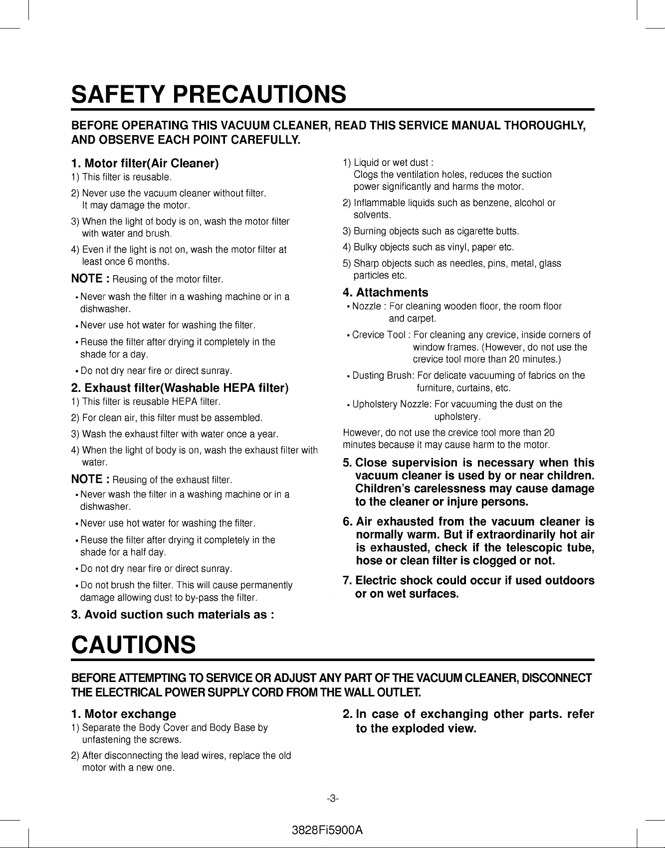
SAFETY
PRECAUTIONS
BEFORE
AND
1.
Motor
This
1)
Never
2)
It
may
When
3)
with
Evenifthe
4)
least
NOTE
Never
dishwasher.
Never
Reuse
shade
Do
2.
Exhaust
This
1)
For
2)
Wash
3)
When
4)
water.
NOTE
Never
dishwasher.
Never
Reuse
shade
Do
Do
damage
3.
Avoid
OPERATING
OBSERVE
filter(Air
filterisreusable.
use
the
vacuum
damage
the
lightofbody
water
and
light
once
6
months.
:
Reusing
wash
the
use
hot
water
the
filter
for
a
day.
not
dry
near
filter(Washable
filterisreusable
clean
the
the
:
wash
use
forahalf
not
not
air,
exhaust
lightofbody
Reusing
the
hot
the
filter
near
dry
brush
allowing
suction
this
water
the
THIS
EACH
POINT
Cleaner)
cleaner
the
motor.
is
on,
brush.
is
not
of
the
filter
after
fireordirect
filter
filter
of
the
filter
after
day.
fireordirect
filter.
dust
wash
on,
motor
in
a
washing
for
washing
dryingitcompletely
HEPA
must
with
is
on,
exhaust
in
a
washing
for
washing
dryingitcompletely
will
This
to
by-pass
such
materials
without
wash
the
filter.
sunray.
filter.
be
assembled.
water
wash
filter.
sunray.
cause
VACUUM
CAREFULLY.
the
motor
machine
the
filter.
HEPA
once
the
exhaust
machine
the
filter.
permanently
the
filter.
filter.
motor
filter
orina
in
the
filter)
a
year.
orina
in
the
as
CLEANER,
filter
at
filter
with
:
READ
1)
Liquid
Clogs
power
Inflammable
2)
solvents.
3)
Burning
4)
Bulky
5)
Sharp
particles
4.
Attachments
Nozzle:For
Crevice
Dusting
Upholstery
However,
minutes
5.
Close
vacuum
Children's
to
Air
6.
normally
is
hose
7.
Electric
or
THIS
SERVICE
or
wet
dust
the
ventilation
significantly
liquids
objects
objects
objects
such
such
etc.
cleaning
and
carpet.
Tool:For
window
crevice
Brush:
Nozzle:
do
not
use
because
supervision
cleaner
carelessness
the
cleaner
exhausted
warm.
exhausted,
or
clean
shock
on
wet
surfaces.
:
holes,
and
such
such
as
as
vinyl,
as
needles,
wooden
cleaning
frames.
tool
For
delicate
furniture,
For
vacuuming
upholstery.
the
crevice
it
cause
may
is
or
injure
from
But
check
filter
could
MANUAL
reduces
harms
the
motor.
as
benzene,
paper
butts.
etc.
cigarette
pins,
the
floor,
crevice,
any
(However,
more
than
vacuuming
curtains,
is
used
etc.
the
tool
more
harmtothe
necessary
by
may
persons.
the
vacuum
if
extraordinarily
if
the
is
clogged
occur
THOROUGHLY,
the
suction
alcohol
metal,
20
dustonthe
or
glass
room
floor
inside
corners
do
not
minutes.)
of
fabricsonthe
than
20
motor.
when
or
near
children.
cause
damage
cleaner
telescopic
or
not.
if
used
outdoors
use
hot
of
the
this
is
air
tube,
CAUTIONS
BEFORE
THE
1.
Motor
1)
Separate
unfastening
After
2)
motor
ATTEMPTING
ELECTRICAL
exchange
the
the
disconnecting
with
a
Body
new
screws.
one.
POWER
Cover
the
lead
TO
and
SERVICE
SUPPLY
Body
wires,
CORD
Base
replace
OR
by
ADJUST
the
FROM
old
3828Fi5900A
ANY
THE
-3-
PART
WALL
2.
In
to
OF
OUTLET.
case
the
THE
VACUUM
of
exchanging
exploded
CLEANER,
view.
other
DISCONNECT
parts.
refer
Page 4

DESCRIPTION
Flexible
Hose
Telesscopic
ASS'Y
Pipe
ASS'Y
Cord
Reel
Button
Switch
Button
(ON/OFF)
(V-C7351NT)
Dust
Tank
Power
Cord
(V-C7353HTU)
Nozzle
ASS'Y
ATTACHMENTS
DUSTING
BRUSH
SPECIFICATIONS
?
MODEL
?
POWER
?
POWER
?
POWER
-
MAIN
-SUB:VACUUM
?
This
buyer's
:
REFER
TO
SOURCE
CONSUMPTION
CONTROL
:
SLIDE
CONTROL
(HE/HTU)
PUSH
ON/OFF(BODY)
(NT)
SLIDE
POWER
KNOB
specifications
request.
THE
:
ON
RATING
:
(NT)
are
subjecttochange
COVER
:
ON
RATING
(F/HOSE)
ADJUSTMENT
PAGE
PLATE
CREVICE
TOOL
PLATE
BY
according
CANISTER
to
the
UPHOLSTERY
NOZZLE
ELBOW
(V-C7352HE)
PIPE
?CORDLENGTH:6m
?
HOSE
?
?
?
?
?
LENGTH
NET
WEIGHT
PACKING
NET
DIMENSION
PACKING
ATTACHMENTS
HOSE.........................................................................
TELESCOPIC
NOZZLE
NOZZLE
ASSY,
ASSY,
DUSTING
CREVICE
UPHOLSTERY
ELBOW
PIPE(OPTIONAL)
:
m
1.6
:
4.5
kg
PIPE
:
8.5
kg
:
280
376 275
:
330
595
........................................
ASSY
(W
335
D
H)mm
D
(W
H)mm
1EA
1EA
WEIGHT
DIMENSION
FLOOR.............................................1EA
TURBINE(OPTIONAL).....................1EA
BRUSH
TOOL
....................................................
.........................................................1EA
NOZZLE
............................................1EA
.........................................1EA
1EA
-4-
3828Fi5900A
Page 5

DISASSEMBLY
NOTE:
?
Almost
disassembled
component
Disassemble
?
If
possible,
parts.
are
not
1.
Body
Remove
1)
Before
attempting
from
the
wall
allofthe
with
easily
one
don't
It
is
not
necessary
detailedinthe
Cover
the
dust
outlet.
of
parts
a
screw
fits
each
one
by
disassemble
exploded
Assembly
tank
from
to
service
this
vacuum
driver
other.
referring
except
to
disassemble
the
or
adjust
cleaner
and
each
connecting
to
the
exploded
for
the
the
view.
Replacement
set.
any
part
can
be
view.
necessary
parts
that
of
the
vacuum
cleaner,
Disassemble
3)
disconnect
the
body
the
cover,
electrical
raising
power
the
supply
body
cord
cover.
2)
Remove
the
four
screws
fastening
the
body
base.
2.
1)
Motor
Remove
cover
the
and
arrow
Assembly
the
two
screws
detach
and
unhook
Replacement
fastening
motor
housing
the
motor
cover
cover
the
motor
in
with
the
" "
housing
direction
driver.
of
-5-
3828Fi5900A
Page 6

2)
3.
1)
Pull
Cord
Lift
the
out
the
Reel
cord
motor
Assembly
reel
assembly
and
disconnect
Replacement
from
the
the
lead
body
wires
base.
from
it.
4.
Disassembly
Remove
1)
the
two
of
screws
Motor
fastening
Housing
the
motor
housing.
-6-
3828Fi5900A
Page 7

TROUBLE
1.
SWITCH
ON
BUT
SHOOTING
MOTOR
DOSE
NOT
GUIDE
TURN.
CHECKING
CAUSE
SOLUTION
2.
SWITCH
ON,
MOTOR
DOES
NOT
TURN
3828Fi5900A
BUT
BUZZES.
-7-
Page 8

3.
SWITCH OFF
4.
WEAK
SUCTION
BUT
MOTOR
POWER
TURNS
-8-
3828Fi5900A
Page 9

5.
VIBRATION
NOISES
6.
RADIO,
TV
RECEPTION
Loose
parts
Unbalanced
Foreign
to
the
impeller.
Poor
carbon
Armature
matters
Poor
cord,
motor
matters
attached.
are
brush
is
cut
or
DISTURBANCE
lead
wire
assembly
attached
rectification
foreign
Secure
firmly.
Exchangeorrepair
Remove
Exchange
Exchange
Remove
Exchange
the
foreign
the
motor.
the
motor
foreign
cord,
matters.
lead
the
motor.
matters.
wire.
7.
IMPROPER
TUBE
Poor
rectification
carbon
OF
Poor
electric
receiver
Poor
capacitor
NOZZLE
Bent
connection
Poor
connection
brush
connector
(Causedbyforeign
of
or
CONNECTION
parts
matters)
Exchange
Repair
or
receiver.
Exchange
Exchange
Remove
and
reconnect.
the
the
the
motor.
electric
the
capacitor.
the
parts.
foreign
connector
matters
-9-
3828Fi5900A
Page 10

SCHEMATIC
DIAGRAM
V-C7351NT
CIRCUIT
DIAGRAM
V-C7351NT
-10-
3828Fi5900A
Page 11

SCHEMATIC
DIAGRAM
V-C7352HE/V-C7353HTU
CIRCUIT
DIAGRAM
V-C7352HE/V-C7353HTU
-11-
3828Fi5900A
Page 12

EXPLODED
VIEW
BASE
ASS'Y,
BODY
146871
135504
146811
139202
139204
152302
252302
249011
135506
168711
139207
146611
145103
149702
166012
235507
252311
235503
130401
146611
144411
-12-
3828Fi5900A
Page 13

COVER
ASS'Y,
136511
BODY
748395
235515
335504
748394
268712
249701
239402
235501
152313
135508
266011
440361
435506
168611
452003
748382
736501
349701
140261
749702
340261
533001
-13-
3828Fi5900A
Page 14

452153
452151
552491
652031
652491
552495
652012
650581
652013
-14-
3828Fi5900A
Page 15

REPLACEMENT
PARTS
LIST
LOCATION
130401
135504
135506
168711
139207
146871
139202
146811
152302
139204
166012
235507
235503
249011
No.
DESCRIPTION
BASE,
BODY
COVER,MOTOR
COVER,MOTOR
PWB
ASSEMBLY,
PACKING,SEAL
CORD
REEL
PACKING,
MOTOR
ASSEMBLY
SPONGE,
PACKING,
SWITCH
COVER,
COVER,
DAMPER
ASSEMBLY,
EXHAUST
EXHAUST
ASSEMBLY
ASSEMBLY
MOTOR
ABSORBING
SEAL
HOUSING
MAIN
MOUNTING
VC
FILTER(L)
FILTER(R)
PRESSURE
PART
Refer
3550FI1794A
3550FI1795B
Refer
3920FI3875A
4687FI1491B
3920FI3908A
Refer
3940FI3646A
3920FI3763A
6601FI3488B
3550FI1801A
3550FI1800A
4901FI2001A
to
appendix
to
appendix
to
appendix
No.
MOTOR
MOTOR
MOTOR
REMARK
HOUSING
252311
252302
146611
145103
149702
144411
235501
435506
135508
335504
136511
452003
235515
168611
440361
268712
FILTER
ASSEMBLY,
FILTER(MECH),
WHEEL
LEVER
SPRING,
CASTER
COVER,
COVER,
COVER,
COVER,
HANDLE
PIPE,
COVER,
WIRE
SEAL,
PWB
ASSEMBLY
CORD,
COIL
ASSEMBLY
BODY
TERMINAL
BODY
TOP
ASSEMBLY
CONNECTOR
DISPLAY
ASSY,
PIPE
ASSEMBLY,
EXHAUST
WINDING
SUB
CONNECTOR
DISPLAY
EXHAUST
5231FI3767C
5230FI4736A
Refer
to
4510FI2439T
4970FI4694F
4441FI3605V
Refer
to
3550FI3802A
Refer
to
Refer
to
Refer
to
5200FI2522A
3550FI3890A
6801FI3464S
3920FI3788A
Refer
to
appendix
appendix
appendix
appendix
appendix
appendix
LEVER
HT
HT
PIPE,
CORD
TYPE
TYPE
CONNECTOR
266011
249701
SWITCH
SPRING,
ASSEMBLY,
BUTTON(SWITCH
POWER
ON/OFF)
-15-
3828Fi5900A
6601FI3149B
4I70024C
NT
TYPE
NT
TYPE
Page 16
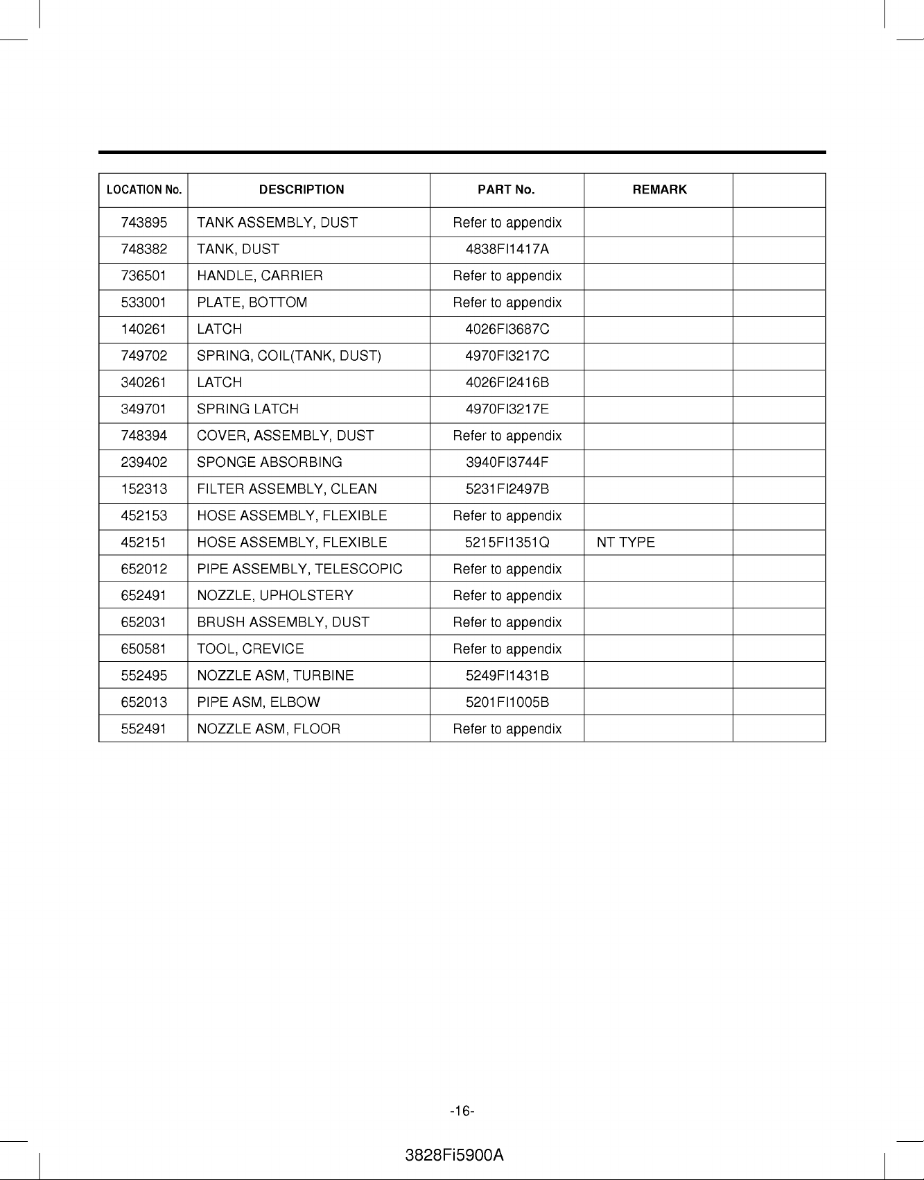
LOCATION
No.
DESCRIPTION
PART
No.
REMARK
743895
748382
736501
533001
140261
749702
340261
349701
748394
239402
152313
452153
452151
652012
652491
652031
TANK
ASSEMBLY,
TANK,
HANDLE,
PLATE,
LATCH
SPRING,
LATCH
SPRING
DUST
CARRIER
BOTTOM
COIL(TANK,
LATCH
COVER, ASSEMBLY,
SPONGE
FILTER
HOSE
HOSE
PIPE
NOZZLE,
BRUSH
ABSORBING
ASSEMBLY,
ASSEMBLY,
ASSEMBLY,
ASSEMBLY,
UPHOLSTERY
ASSEMBLY,
DUST
DUST)
DUST
CLEAN
FLEXIBLE
FLEXIBLE
TELESCOPIC
DUST
Refer
to
4838FI1417A
Refer
to
Refer
to
4026FI3687C
4970FI3217C
4026FI2416B
4970FI3217E
Refer
to
3940FI3744F
5231FI2497B
Refer
to
5215FI1351Q
Refer
to
Refer
to
Refer
to
appendix
appendix
appendix
appendix
appendix
appendix
appendix
appendix
NT
TYPE
650581
552495
652013
552491
TOOL,
NOZZLE
PIPE
NOZZLE
CREVICE
ASM,
ASM,
ASM,
ELBOW
TURBINE
FLOOR
Refer
5249FI1431B
5201FI1005B
Refer
to
appendix
to
appendix
-16-
3828Fi5900A
Page 17

APPENDIX
1.
THE
TYPE
OF
POWER
CORD
&
PARTS
NUMBER
TYPE TYPE
A-1
S-1
C-2
OF PLUG
17
17
19
6.3
12.7
19
4.8
CORD
REEL
4687FI1491B
ASS'Y
P/NO
(L/NO.:146871)
(V-C7351NT/V-C7352HE/V-C7353HTU)
C-1
B-3
Color
of
fuse
Brown
Yellow
Blue
19
4
19
identification
13A
5A
3A
-17-
3828Fi5900A
Page 18
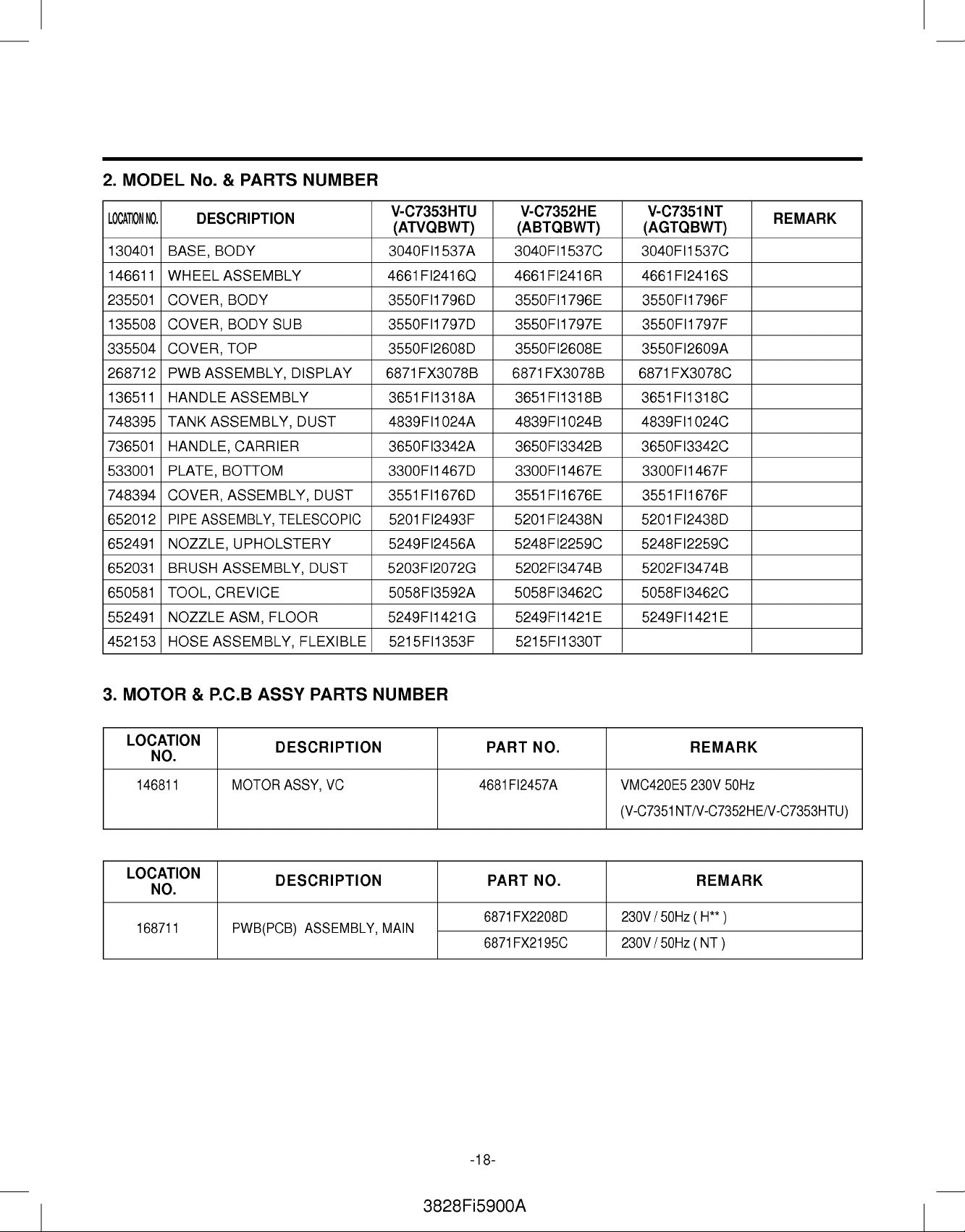
2.
MODEL
No.
&
PARTS
NUMBER
LOCATION
130401
146611
235501
135508
335504
268712
136511
748395
736501
533001
748394
652012
652491
652031
650581
552491
452153
NO.
DESCRIPTION
BASE,
WHEEL
COVER,
COVER,
COVER,
PWB
HANDLE
TANK
HANDLE,
PLATE,
COVER,
PIPE
NOZZLE,
BRUSH
TOOL,
NOZZLE
HOSE
BODY
ASSEMBLY
BODY
BODY
TOP
ASSEMBLY,
ASSEMBLY
ASSEMBLY,
CARRIER
BOTTOM
ASSEMBLY,
ASSEMBLY,
UPHOLSTERY
ASSEMBLY,
CREVICE
ASM,
ASSEMBLY,
SUB
DISPLAY
DUST
TELESCOPIC
FLOOR
FLEXIBLE
DUST
DUST
V-C7353HTU
(ATVQBWT)
3040FI1537A
4661FI2416Q
3550FI1796D
3550FI1797D
3550FI2608D
6871FX3078B
3651FI1318A
4839FI1024A
3650FI3342A
3300FI1467D
3551FI1676D
5201FI2493F
5249FI2456A
5203FI2072G
5058FI3592A
5249FI1421G
5215FI1353F
V-C7352HE
(ABTQBWT)
3040FI1537C
4661FI2416R
3550FI1796E
3550FI1797E
3550FI2608E
6871FX3078B
3651FI1318B
4839FI1024B
3650FI3342B
3300FI1467E
3551FI1676E
5201FI2438N
5248FI2259C
5202FI3474B 5202FI3474B
5058FI3462C
5249FI1421E 5249FI1421E
5215FI1330T
V-C7351NT
(AGTQBWT)
3040FI1537C
4661FI2416S
3550FI1796F
3550FI1797F
3550FI2609A
6871FX3078C
3651FI1318C
4839FI1024C
3650FI3342C
3300FI1467F
3551FI1676F
5201FI2438D
5248FI2259C
5058FI3462C
REMARK
3.
MOTOR
LOCATION
NO.
146811
LOCATION
NO.
168711
&
P.C.B
ASSY
DESCRIPTION
MOTOR
DESCRIPTION
PWB(PCB)
ASSY,
ASSEMBLY,
PARTS
VC
NUMBER
MAIN
PART
4681FI2457A
PART
6871FX2208D
6871FX2195C
NO.
NO.
REMARK
VMC420E5
230V
50Hz
(V-C7351NT/V-C7352HE/V-C7353HTU)
REMARK
230V/50Hz(H**)
230V/50Hz(NT)
-18-
3828Fi5900A
Page 19

3828Fi5900A
Page 20

P/No.:3828Fi5900A
August.
PrintedinKorea
2004
 Loading...