


INSTALLATION MANUAL
AIR
CONDITIONER
www.lg.com
Please read this installation manual completely before installing the product.
Installation work must be performed in accordance with the national wiring
standards by authorized personnel only.
Please retain this installation manual for future reference after reading
it thoroughly.
Original instruction
MFL71666401
Rev.01_121719
Copyright © 2019 LG Electronics Inc. All Rights Reserved.
[Representative] LG Electronics Inc. EU Representative : LG Electronics European Shared
Service Center B.V. Krijgsman 1, 1186 DM Amstelveen, The Netherlands
[Manufacturer] LG Electronics Inc. Changwon 2nd factory 84, Wanam-ro, Seongsan-gu,
Changwon-si, Gyeongsangnam-do, KOREA
ENGLISH
ITALIANO ESPAÑOL
FRANÇAIS DEUTSCH
ΕΛΛΗΝΙΚΆ
ČEŠTINA
NEDERLANDS
POLSKI
LIMBA ROMÂNĂ
MODEL DESIGNATION
2
ENGLISH
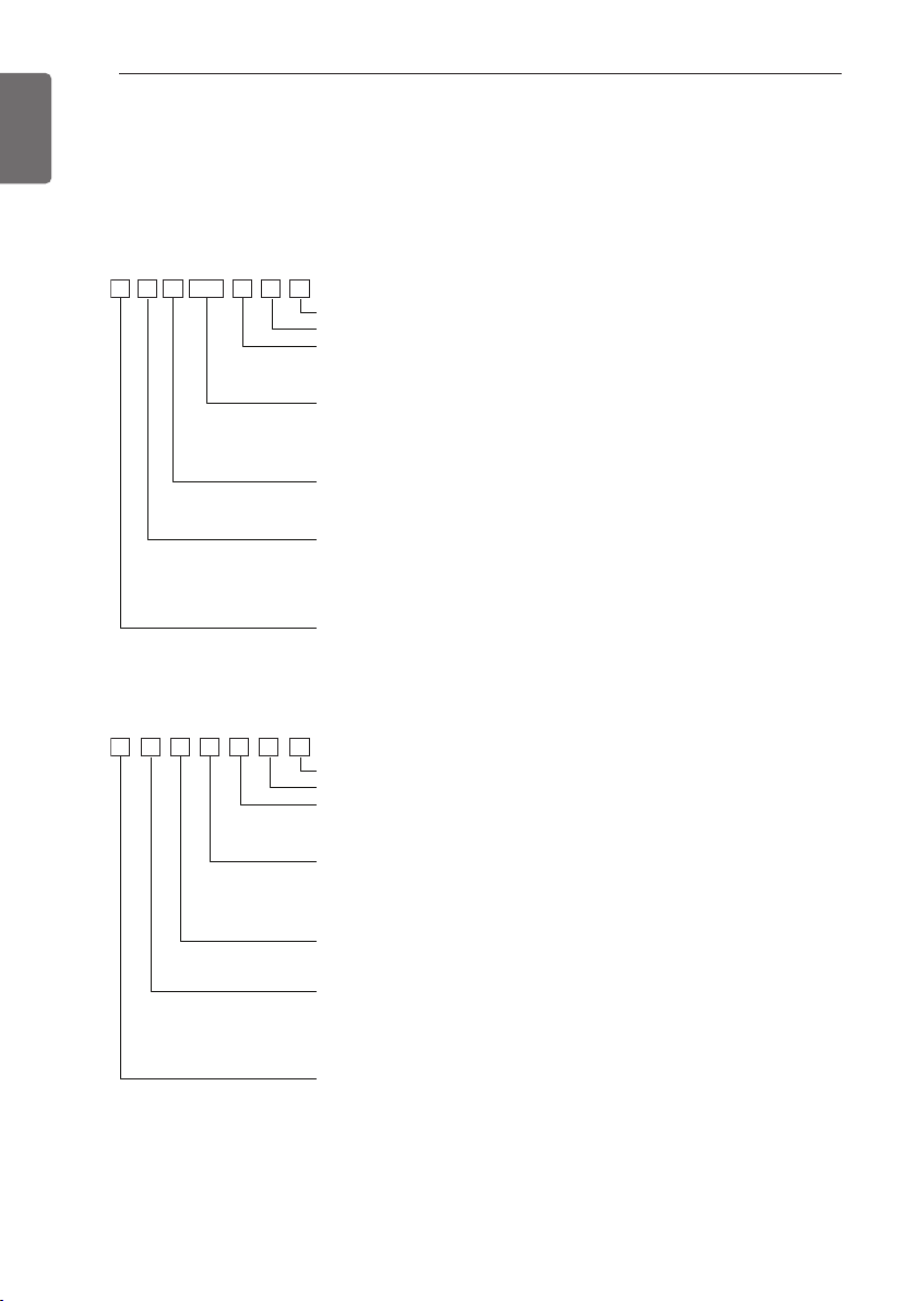
MODEL DESIGNATION
Product information
- Product Name : Air conditioner
- Model Name :
• Indoor Unit for Multi System
SQSM N B 015
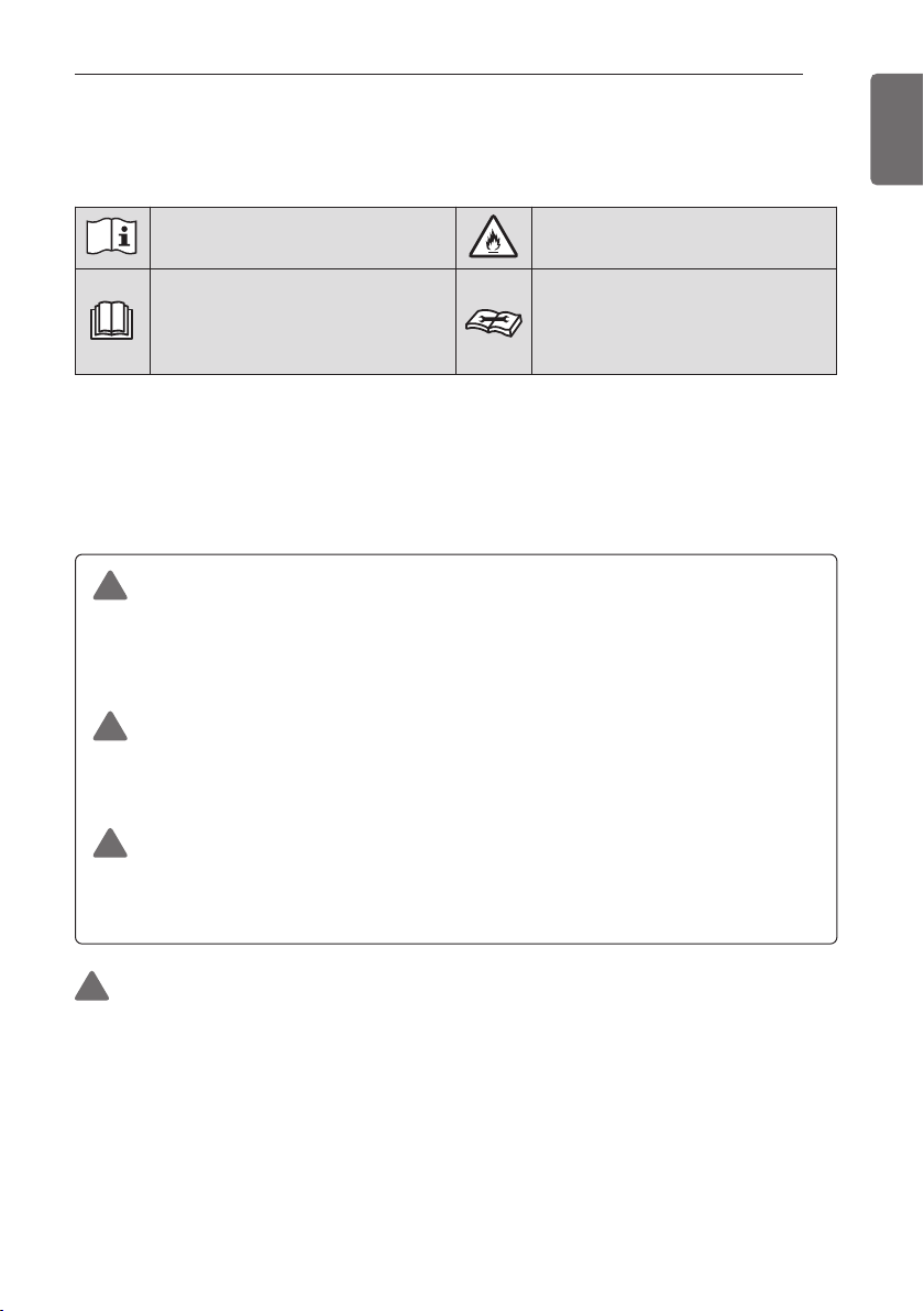
• Indoor units only for Single A Systems
• Common Indoor Unit for Multi and Single CAC
FTCNB018
Serial number
Chassis name
Indoor Unit / Outdoor Units
N : Indoor Unit
U : Outdoor Unit
Detailed product type
AQ : Wall mounted Libero-R
SQ : Wall mounted Libero-E
AH : Ceiling Cassette
Nominal Capacity
Ex) 7 000 Btu/h Class → '07',
18 000 Btu/h Class → '18'
Product type
S : Wall mounted / ARTCOOL mirror
J : Wall mounted
A : ARTCOOL
T : Ceiling Cassette
Connectable Outdoor unit type
M : Indoor units only for Multi systems
Serial number
Chassis name
Indoor Unit / Outdoor Units
N : Indoor Unit
U : Outdoor Unit
Detailed product type
L : Low Static
H : High COP
C : Econo
Nominal Capacity
Ex) 7 000 Btu/h Class → '07',
18 000 Btu/h Class → '18'
Product type
S : Wall mounted / ARTCOOL mirror
J : Wall mounted
A : ARTCOOL
T : Ceiling Cassette
Connectable Outdoor unit type
U : Indoor units only for Single A systems
C : Common Indoor Unit for Multi and Single CAC
AH* : ARTCOOL *=0, 1, 2 (Ex . AH1)
AW* : ART COOL Mirror *=0, 1, 2 (Ex. AW1)
AHL : Ceiling Concealed Duct (Low Static)
B, M, L : Ceiling Concealed Duct
V : Ceiling Suspended & floor
Q : Console
P : Floor Standing
R : Refrigerant R32 / R410A
FH : Free combination High COP
F : Free combination
B, M, L : Ceiling Concealed Duct
V : Ceiling Suspended & floor
Q : Console
P : Floor Standing
- Additional Information : serial number is refer to the barcode on the product.
- Maximum allowable pressure High side : 4.2 MPa / 4.32 MPa (it can be different by model)
Maximum allowable pressure Low side : 2.4 MPa
- Refrigerant : R32

MODEL DESIGNATION
Airborne Noise Emission
The A-weighted sound pressure emitted by this product is below 70 dB.
** The noise level can vary depending on the site.
The figures quoted are emission level and are not necessarily safe working levels.
Whilst there is a correlation between the emission and exposure levels, this cannot be used
reliably to determine whether or not further precautions are required.
Factor that influence the actual level of exposure of the workforce include the characteristics of
the work room and the other sources of noise, i.e. the number of equipment and other adjacent
processes and the length of time for which an operator exposed to the noise. Also, the
permissible exposure level can vary from country to country.
This information, however, will enable the user of the equipment to make a better evaluation of
the hazard and risk.
3
ENGLISH

TIPS FOR SAVING ENERGY
4
ENGLISH
TIPS FOR SAVING ENERGY
Here are some tips that will help you minimize the power consumption when you use the air
conditioner. You can use your air conditioner more efficiently by referring to the instructions
below:
• Do not cool excessively indoors. This may be harmful for your health and may consume more
electricity.
• Block sunlight with blinds or curtains while you are operating the air conditioner.
• Keep doors or windows closed tightly while you are operating the air conditioner.
• Adjust the direction of the air flow vertically or horizontally to circulate indoor air.
• Speed up the fan to cool or warm indoor air quickly, in a short period of time.
• Open windows regularly for ventilation as the indoor air quality may deteriorate if the air
conditioner is used for many hours.
• Clean the air filter once every 2 weeks. Dust and impurities collected in the air filter may block the
air flow or weaken the cooling / dehumidifying functions.
For your records
Staple your receipt to this page in case you need it to prove the date of purchase or for warranty
purposes. Write the model number and the serial number here:
Model number :
Serial number :
You can find them on a label on the side of each unit.
Dealer’s name :
Date of purchase :
SAFETY INSTRUCTIONS
The following symbols are displayed on indoor and outdoor units.
SAFETY INSTRUCTIONS
5
ENGLISH
Read the precautions in this manual
carefully before operating the unit.
This symbol indicates that the
Operation Manual should be read
carefully.
This appliance is filled with
flammable refrigerant.(for R32)
This symbol indicates that a service
personnel should be handling this
equipment with reference to the
Installation Manual.
The following safety guidelines are intended to prevent
unforeseen risks or damage from unsafe or incorrect operation
of the appliance.
The guidelines are separated into ‘WARNING’ and ‘CAUTION’ as
described below.
This symbol is displayed to indicate matters and operations
!
that can cause risk.
Read the part with this symbol carefully and follow the
instructions in order to avoid risk.
WARNING
!
This indicates that the failure to follow the instructions can cause
serious injury or death.
CAUTION
!
This indicates that the failure to follow the instructions can cause
the minor injury or damage to the product.
WARNING
!
• Installation or repairs made by unqualified persons can result in
hazards to you and others.
• The information contained in the manual is intended for use by
a qualified service technician familiar with safety procedures
and equipped with the proper tools and test instruments.
• Failure to carefully read and follow all instructions in this
manual can result in equipment malfunction, property damage,
personal injury and/or death.

SAFETY INSTRUCTIONS
6
ENGLISH
• Compliance with national gas regulations shall be observed.
• Ducts connected to an appliance shall not contain an ignition
source. (for R32)
Installation
• Always perform grounding.
- Otherwise, it may cause electrical shock.
• Don’t use a power cord, a plug or a loose socket which is
damaged.
- Otherwise, it may cause a fire or electrical shock.
• For installation of the product, always contact the service center or
a professional installation agency.
Otherwise, it may cause a fire, electrical shock, explosion or injury.
-
• Securely attach the electrical part cover to the indoor unit and the
service panel to the outdoor unit.
- If the electrical part cover of the indoor unit and the service panel
of the outdoor unit are not attached securely, it could result in a
fire or electric shock due to dust, water, etc.
Always install an air leakage breaker and a dedicated switching board.
•
- No installation may cause a fire and electrical shock.
• Do not keep or use flammable gases or combustibles near the air
conditioner.
- Otherwise, it may cause a fire or the failure of product.
• Ensure that an installation frame of the outdoor unit is not
damaged due to use for a long time.
- It may cause injury or an accident.
• Do not disassemble or repair the product randomly.
- It will cause a fire or electrical shock.
• Do not install the product at a place that there is concern of falling
down.
- Otherwise, it may result in personal injury.
• Use caution when unpacking and installing.
- Sharp edges may cause injury.
• The appliance shall be stored in a room without continuously
operating open flames (for example an operating gas appliance)
and ignition sources (for example an operating electric heater).

SAFETY INSTRUCTIONS
7
• Two or more people must lift and transport the product. Avoid
personal injury.
• Do not use means to accelerate the defrosting process or to clean,
other than those recommended by the manufacturer.
• Do not pierce or burn refrigerant cycle part.
• Be aware that refrigerants may not contain an odour.
• Keep any required ventilation openings clear of obstruction.
The appliance shall be stored in a well-ventilated area where the room
•
size corresponds to the room area as specified for operation. (for R32)
• Refrigerant tubing shall be protected or enclosed to avoid damage.
• Flexible refrigerant connectors (such as connecting lines between
the indoor and outdoor unit) that may be displaced during normal
operations shall be protected against mechanical damage.
• A brazed, welded, or mechanical connection shall be made before
opening the valves to permit refrigerant to flow between the
refrigerating system parts.
• Mechanical connections shall be accessible for maintenance
purposes.
• The appliance shall be disconnected from its power source during
service and when replacing parts.
• The appliance shall be installed in accordance with national wiring
regulations.
ENGLISH
Operation
• Do not share the outlet with other appliances.
- It will cause an electric shock or a fire due to heat generation.
• Do not use the damaged power cord.
- Otherwise, it may cause a fire or electrical shock.
• Do not modify or extend the power cord randomly.
- Otherwise, it may cause a fire or electrical shock.
Take care so that the power cord may not be pulled during operation.
•
- Otherwise, it may cause a fire or electrical shock.
• Unplug the unit if strange sounds, smell, or smoke comes from it.
- Otherwise, it may cause electrical shock or a fire.
• Keep the flames away.
- Otherwise, it may cause a fire.

SAFETY INSTRUCTIONS
8
ENGLISH
• Take the power plug out if necessary, holding the head of the plug
and do not touch it with wet hands.
- Otherwise, it may cause a fire or electrical shock.
• Do not use the power cord near the heating tools.
- Otherwise, it may cause a fire and electrical shock.
• Do not open the suction inlet of the indoor/outdoor unit during
operation.
- Otherwise, it may electrical shock and failure.
• Do not allow water to run into electrical parts.
- Otherwise, it may cause the failure of machine or electrical shock.
• Hold the plug by the head when taking it out.
- It may cause electric shock and damage.
• Never touch the metal parts of the unit when removing the filter.
- They are sharp and may cause injury.
• Do not step on the indoor/outdoor unit and do not put anything on
it.
- It may cause an injury through dropping of the unit or falling
down.
• Do not place a heavy object on the power cord.
- Otherwise, it may cause a fire or electrical shock.
• When the product is submerged into water, always contact the
service center.
- Otherwise, it may cause a fire or electrical shock.
• Take care so that children may not step on the outdoor unit.
- Otherwise, children may be seriously injured due to falling down.
• Use a vacuum pump or inert (nitrogen) gas when doing leakage
test or air purge. Do not compress air or oxygen, and do not use
flammable gases. Otherwise, it may cause fire or explosion.
- There is the risk of death, injury, fire or explosion.
• Do not turn on the breaker or power under condition that front
panel, cabinet, top cover, control box cover are removed or
opened.
- Otherwise, it may cause fire, electric shock, explosion or death.
• Turn off all devices that cause fire when the refrigerant leaks.,
ventilate the room (example : opening window or using ventilation
unit), and contact with dealer who you purchased the unit.

SAFETY INSTRUCTIONS
9
• The installation of pipe-work shall be kept to a minimum.
• When mechanical connectors are reused indoors, sealing parts
shall be renewed. (for R32)
• When flared joints are reused indoors, the flare part shall be refabricated. (for R32)
CAUTION
!
Installation
• Install the drain hose to ensure that drain can be securely done.
- Otherwise, it may cause water leakage.
• Install the product so that the noise or hot wind from the outdoor
unit may not cause any damage to the neighbors.
- Otherwise, it may cause dispute with the neighbors.
• Always inspect gas leakage after the installation and repair of
product.
- Otherwise, it may cause the failure of product.
• Keep level parallel in installing the product.
- Otherwise, it may cause vibration or water leakage.
• Any person who is involved with working on or breaking into a
refrigerant circuit should hold a current valid certificate from an
industry-accredited assessment authority, which authorises their
competence to handle refrigerants safely in accordance with an
industry recognized assessment specification. (for R32)
• Wear adequate personal protection equipment (PPE) when
installing, maintaining or servicing the product.
• Pipe-work shall be protected from physical damage.
ENGLISH
Operation
• Avoid excessive cooling and perform ventilation sometimes.
- Otherwise, it may do harm to your health.
• Use a soft cloth to clean. Do not use wax, thinner, or a strong
detergent.
- The appearance of the air conditioner may deteriorate, change
color, or develop surface flaws.

SAFETY INSTRUCTIONS
10
ENGLISH
• Do not use an appliance for special purposes such as preserving
animals vegetables, precision machine, or art articles.
- Otherwise, it may damage your properties.
• Do not place obstacles around the flow inlet or outlet.
- Otherwise, it may cause the failure of appliance or an accident.
• The appliance shall be stored so as to prevent mechanical damage
from occurring.
• Servicing shall only be performed as recommended by the
equipment manufacturer. Maintenance and repair requiring the
assistance of other skilled personnel shall be carried out under the
supervision of the person competent in the use of flammable
refrigerants. (for R32)
• Dismantling the unit, treatment of the refrigerant oil and eventual
parts should be done in accordance with local and national
standards.
• Periodic ( more than once/year ) cleaning of the dust or salt
particles stuck on the heat exchanger by using water.
• Means for disconnection must be incorporated in the fixed wiring
in accordance with the wiring rules.
• This appliance is not intended for use by persons (including
children) with reduced physical, sensory or mental capabilities or
lack of experience and knowledge, unless they have been given
supervision or instruction concerning use of the appliance by a
person responsible for their safety.
Children should be supervised to ensure that they do not play with
the appliance.
• This appliance can be used by children aged from 8 years and
above and persons with reduced physical, sensory or mental
capabilities or lack of experience and knowledge if they have been
given supervision or instruction concerning use of the appliance in
a safe way and understand the hazards involved. Children shall not
play with the appliance. Cleaning and user maintenance shall not
be made by children without supervision.
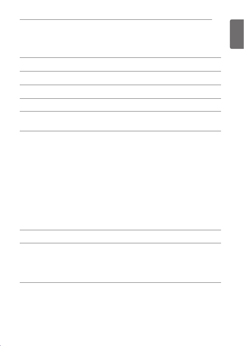
TABLE OF CONTENTS
2 MODEL DESIGNATION
4 TIPS FOR SAVING ENERGY
5 SAFETY INSTRUCTIONS
12 INTRODUCTION
17 INSTALLATION PLACES
17 Select the best Location
23 THE INDOOR UNIT INSTALLATION
24 Position of suspension Bolt
28 Fixing Installation Plate
29 Connecting the Piping
38 Open side-cover
39 Mounting the anchor nut and bolt
41 Indoor Unit Drain Piping
43 Drain test
45 Wiring Connection
48 Electrical Wiring
48 Flaring Work
51 Test Running
53 Heating Only Mode
54 SMART DIAGNOSIS (Optional)
55 Manual the decor, air filter Assembly & Disassembly
TABLE OF CONTENTS
11
ENGLISH
57 INSTALLATION OF DECORATIVE PANEL(ACCESSORY)
61 INSTALLATION INSTRUCTIONS
61 Installer Setting - How to enter installer setting mode
62 Installer Setting - Installer Setting Code Table
63 Installer Setting - Setting Address of Central Control
63 Installer Setting - Checking Address of Central Control
68 DIP SWITCH SETTING
INTRODUCTION
12
ENGLISH
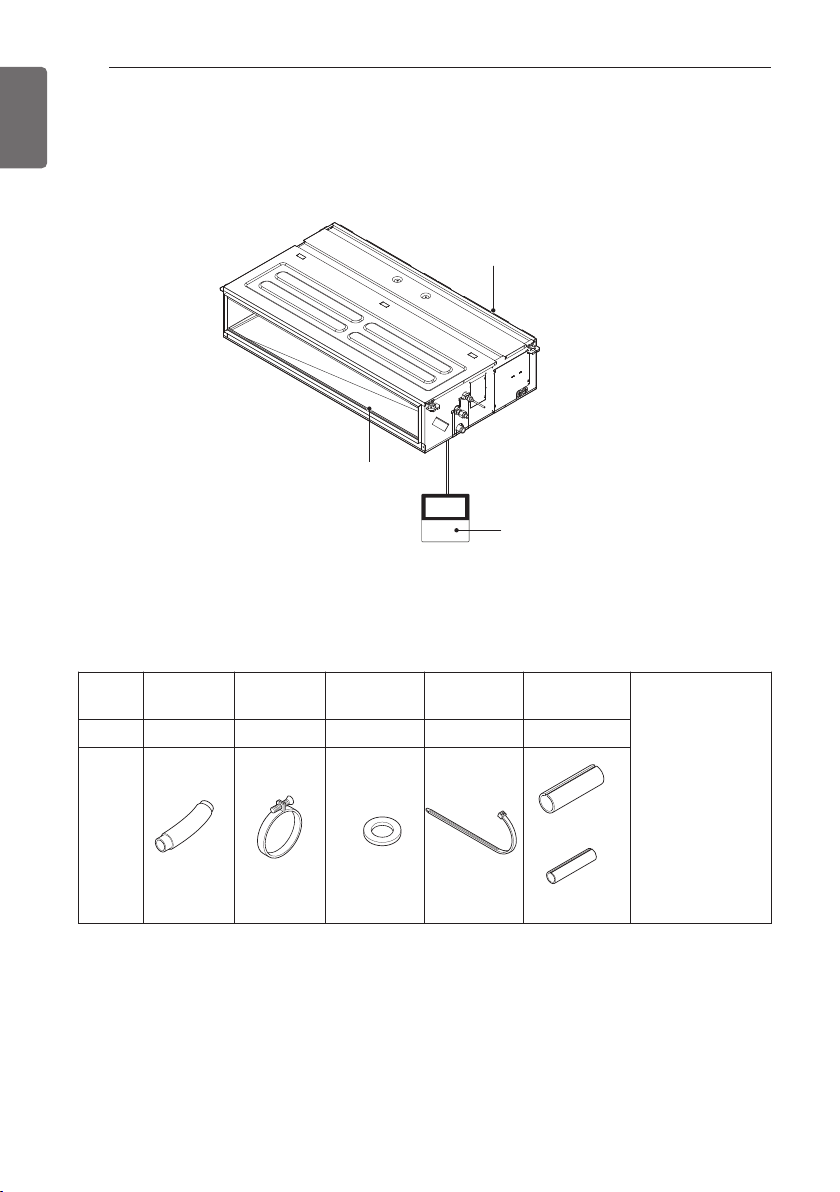
INTRODUCTION
[Ceiling Concealed Duct]
Air outlet vents
Air inlet vents
Remote Controller
(Accessory)
Installation Tool
Name Drain hose Clamp metal
Quantity
Shape
1 EA 2 EA 8 EA 4 EA 1 SET
Washer for
hanging bracket
Clamp
(Tie Wrap)
Insulation for
fitting
for gas pipe
for liquid pipe
(Other)
• Manual
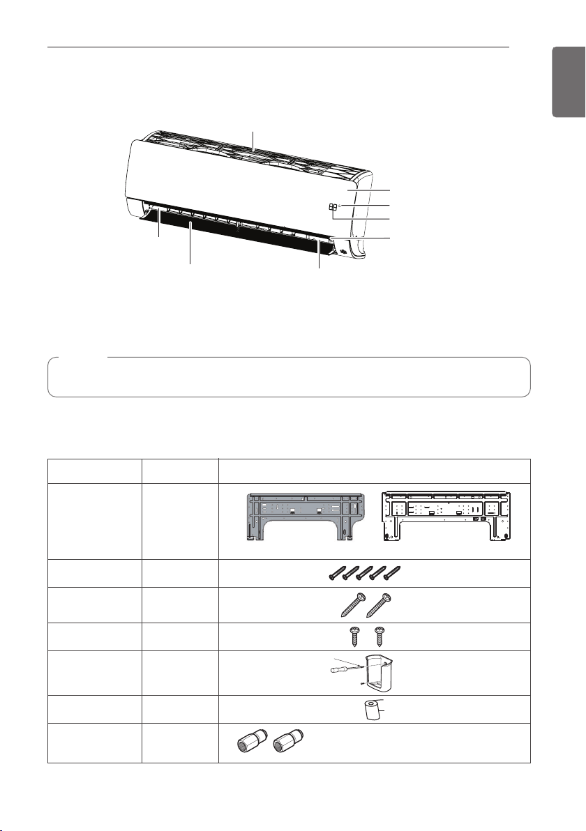
[Wall Mounted]
Name
Quantity Shape
Installation plate
1 EA
Cloth tape
Connector
1 EA
Type "A" screw
5 EA
Type "B" screw
2 EA
Type "C" screw
2 EA
Remote control
holder
1 EA
1 EA (5.0 kW)
2 EA (6.6 kW)
The feature can be changed according to type of model.
Type “B” screw
5.0 kW : ڸØ9.52 (3/8) ơ Ø12.7 (1/2)
6.6 kW : ڸØ9.52 (3/8) ơ Ø12.7 (1/2)
ڹØ15.88 (5/8) ơ Ø12.7 (1/2)
Air outlet
Air filter
INTRODUCTION
Front grille
Signal receiver
Display
On/Off button
13
ENGLISH
(Vertical louver & Horizontal vane)
* The feature can be changed according to type of model.
Air deflector
NOTE
• When mechanical connectors are reused indoors, sealing parts shall be renewed.
Installation Tool
Plasmaster Ionizer
(Other) Manual
INTRODUCTION
14
ENGLISH
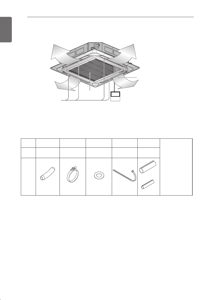
[Ceiling Cassette]
Installation Tool
Name
Quantity
Air Outlet
Drain hose
1 EA
Clamp metal
2 EA
Air Intake
Wired Remote Controller
(Accessory)
Washer for
hanging bracket
8 EA
Clamp
(Tie Wrap)
4 EA
Anti-bacteria filter
Insulation for
fitting
1 SET
(Other)
Shape
• Screws for fixing panels are attached to decoration panel.
• Paper pattern for
installation
• Manual
for gas pipe
for liquid pipe
Name
Quantity
Shape
- Remote Controller
- Remote Controller Holder
- Battery (AAA) - 2 EA
- Allergy Filter
- Fixing Screw for R.Controller
Holder - 2 EA
- Fixing screw for Installation
Plate 4*25 mm - 5 EA
- Wood screw for indoor fixation - 2 EA
- Manual
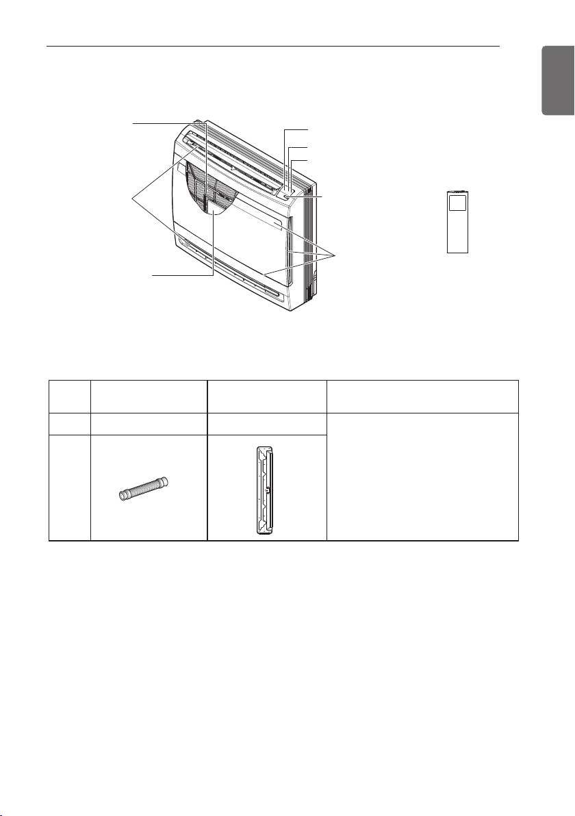
Installation Plate
1 EA
Other
Drain Hose
1 EA
[Console]
INTRODUCTION
15
ENGLISH
Air filter
Air outlet
Allergy filter
Installation Tool
Signal receiver
Operation lamp
Air purifier lamp
ON/OFF button
Air inlet
Remote Controller
(Accessory)
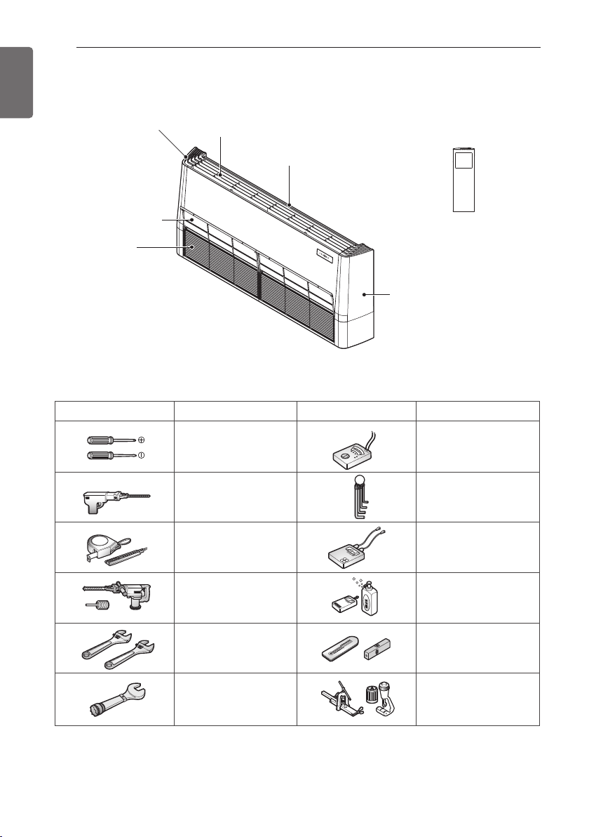
INTRODUCTION
16
ENGLISH
[Ceiling suspended type]
Right side cover
Air filters
(behind inlet grille)
Air inlet vent
(inlet grille)
Installation Tool
Figure FigureName
Louver
Screw driver
Electric drill
Air outlet vent
Remote Controller
(Accessory)
Left side cover
Name
Multi-meter
Hexagonal wrench
(Other) Manual
Measuring tape, Knife
Hole core drill
Spanner
Torque wrench
Ammeter
Gas-leak detector
Thermometer,
Level
Flaring tool set
INSTALLATION PLACES
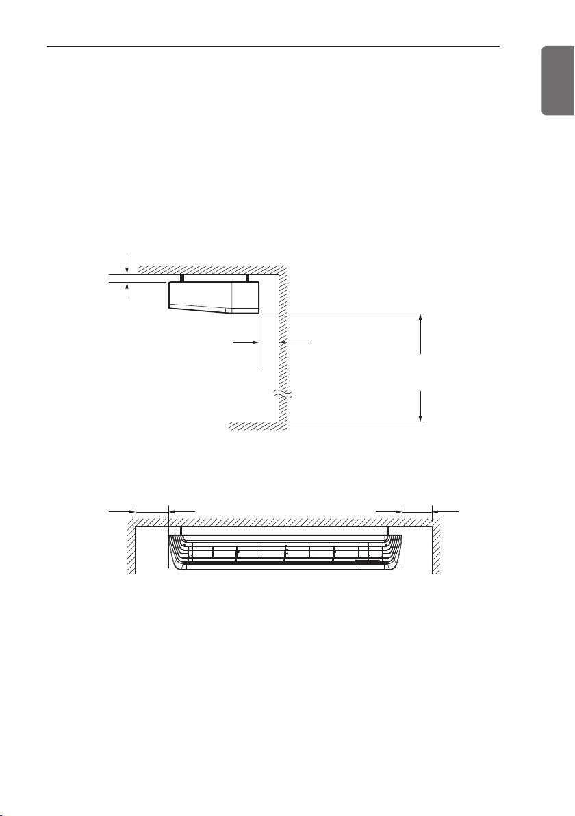
INSTALLATION PLACES
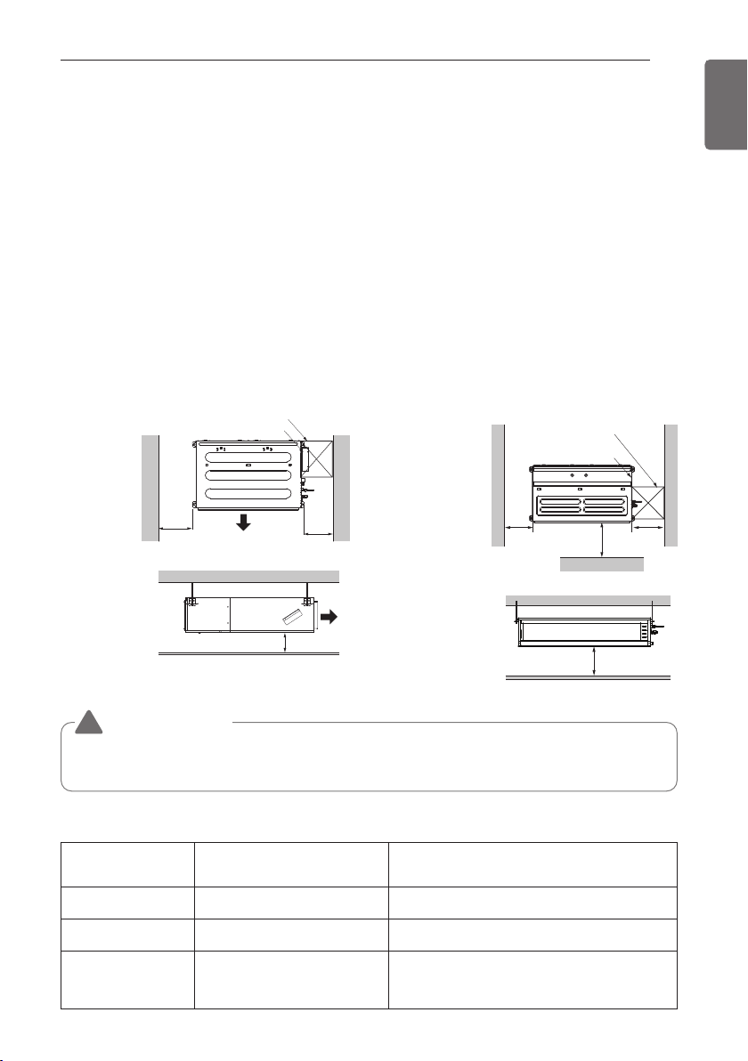
Select the best Location
[Ceiling Concealed Duct]
- The place shall easily bear a load exceeding four times the indoor unit’s weight.
- The place shall be able to inspect the unit as the figure.
- The place where the unit shall be leveled.
- The place shall allow easy water drainage.
(Suitable dimension “H” is necessary to get a slope to drain as figure.)
- The place shall easily connect with the outdoor unit.
- The place where the unit is not affected by an electrical noise.
- The place where air circulation in the room will be good .
- There should not be any heat source or steam near the unit.
Ceiling Concealed Duct – Low Static Ceiling Concealed Duct – Mid Static
Top view
(unit: mm)
Inspection hole (600 x 600)
Control box
Top view
(unit: mm)
Inspection hole
(600 x 600)
Control box
17
ENGLISH
600
or More
Side view
(unit: mm)
• Suitable dimension "H" is necessary to get a slope
to drain as shown in the figure
CAUTION
!
Air outlet
600
or More
H
= 20 or More
Air outlet
Front view
600
or More
1 000
or More
Front
H
= 20 or More
• In case that the unit is installed near the sea, the installation parts may be corroded by salt,
The installation parts (and the unit) should be taken appropriate anti-corrosion measures.
Inspection Hole Standard
Number of
Inspection hole
1 More than 100 cm Sufficient space in the ceiling for servicing.
2 20 cm to 100 cm Insufficient space. Difficult for servicing
Hole size should be
more than the size
of IDU.
Distance between
False ceiling & Actual ceiling
Remarks
Less than 20 cm Minimum height for motor replacement.
600
or More
INSTALLATION PLACES
More Than
200
More Than
100
More Than
100
More Than
2 300
More Than
500
More Than
500
More Than
200
More Than
1 500
18
ENGLISH
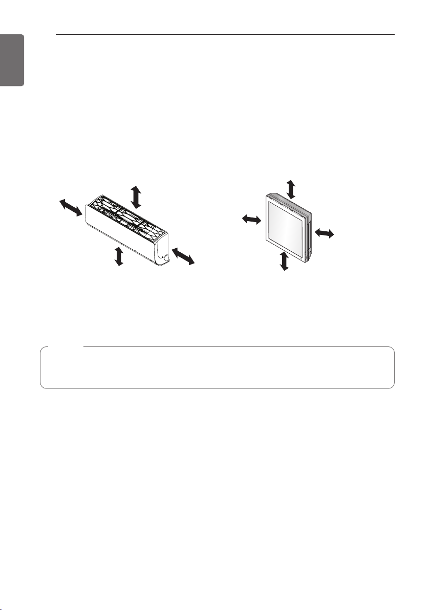
[Wall Mounted]
- There should not be any heat or steam near the unit.
- Select a place where there are no obstacles around of the unit.
- Make sure that condensation drainage can be conveniently routed away.
- Do not install near a doorway.
- Ensure that the interval between a wall and the left (or right) of the unit is more than 100 mm.
The unit should be installed as high as possible on the wall, allowing a minimum of 200 mm
from ceiling.
- Use a metal detector to locate studs to prevent unnecessary damage to the wall.
* The feature can be changed according to type of model.
(Unit: mm)
NOTE
The gap between the indoor unit and ceiling is needed more than 200 mm for disassemble
the air filter.
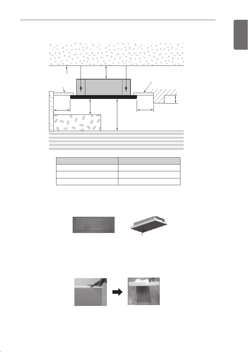
[Ceiling Cassette]
Annexed sheet
Or
Packing corrugated
cardboard on the
bottom
Ceiling
Ceiling Board
10 or
more
INSTALLATION PLACES
Ceiling Board
19
ENGLISH
500 or
more
1 000
or more
H
Floor
500 or
more
Unit : mm
300 or less
At least 1 800
H or less
Chassis H
TU 3 300
TQ / TR / TP / TP-B 3 600
TN / TM / TM-A 4 200
* Please use an annexed sheet or the corrugated cardboard on the bottom of packing as
installation sheet.
* When using the bottom sheet, please use it after separating the installation sheet from packing
of the product floor by using a knife etc as a picture below.
INSTALLATION PLACES
20
ENGLISH
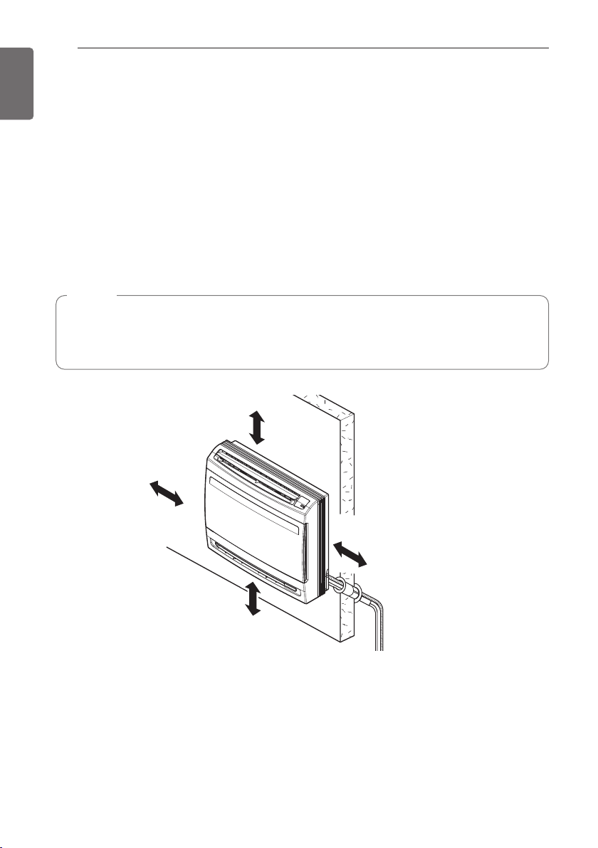
[Console]
- There should not be any heat or steam near the unit.
- Select a place where there are no obstacles around of the unit.
- Make sure that condensation drainage can be conveniently routed away.
- Do not install near a doorway.
- Ensure that the interval between a wall and the left (or right) of the unit is more than 300 mm.
- Use a metal detector to locate studs to prevent unnecessary damage to the wall.
- Keep away from electronic ignition type fluorescent lamps as they may shorten the remote
controller range.
- Please check at least 1 m away from television or radio.(It cause interference with the picture
or sound.)
NOTE
• Before choosing the installation site, please obtain user approval
• If the unit is installed below a window, check the interference of window curtain.(more than
300 mm)
More than 300
More than
300
250 or below
from the Floor
More than
300
(Unit : mm)
INSTALLATION PLACES
700(27 – 9/16) or more 700(27 – 9/16) or more
2 500 (98 – 3/7)
or more
Floor
10 (13/32)
or more
300 (11 – 13/16)
or more
(Unit : mm)
[Ceiling suspended type]
- There should not be any heat source or steam near the unit.
- There should not be any obstacles to prevent the air circulation.
- A place where air circulation in the room will be good.
- A place where drainage can be easily obtained.
- A place where noise prevention is taken into consideration.
- Do not install the unit near the door way.
- Ensure the spaces indicated by arrows from the wall, ceiling, or other obstacles.
- The indoor unit must keep the maintenance space.
21
ENGLISH

ENGLISH
0
100
200
300
400
500
600
Amin (m2)
m (kg)
0 1.224 2 3 4 5 6 7 8
Floor standing
Wall mounted
Ceiling mounted
INSTALLATION PLACES
22
Minimum floor area (for R32)
- The appliance shall be installed, operated and stored in a room with a floor area larger than the
minimum area.
- Use the graph of table to determine the minimum area.
- m : Total refrigerant amount in the system
- Total refrigerant amount : factory refrigerant charge + additional refrigerant amount
- Amin : minimum area for installation
Floor standing
m (kg) Amin (m
< 1.224
1.224 12.9
1.4 16.82
1.6 21.97
1.8 27.80
2 34.32
2.2 41.53
2.4 49.42
2.6 58.00
2.8 67.27
3 77.22
3.2 87.86
3.4 99.19
3.6 111.20
3.8 123.90
4 137.29
4.2 151.36
4.4 166.12
2
)
-
Floor standing
m (kg) Amin (m
4.6 181.56
4.8 197.70
5 214.51
5.2 232.02
5.4 250.21
5.6 269.09
5.8 288.65
6 308.90
6.2 329.84
6.4 351.46
6.6 373.77
6.8 396.76
7 420.45
7.2 444.81
7.4 469.87
7.6 495.61
7.8 522.04
2
)
Wall mounted
m (kg) Amin (m
< 1.224
1.224 1.43
1.4 1.87
1.6 2.44
1.8 3.09
2 3.81
2.2 4.61
2.4 5.49
2.6 6.44
2.8 7.47
3 8.58
3.2 9.76
3.4 11.02
3.6 12.36
3.8 13.77
4 15.25
4.2 16.82
4.4 18.46
2
)
-
Wall mounted
m (kg) Amin (m
4.6 20.17
4.8 21.97
5 23.83
5.2 25.78
5.4 27.80
5.6 29.90
5.8 32.07
6 34.32
6.2 36.65
6.4 39.05
6.6 41.53
6.8 44.08
7 46.72
7.2 49.42
7.4 52.21
7.6 55.07
7.8 58.00
2
)
Ceiling Mounted
m (kg) Amin (m
< 1.224
1.224 0.956
1.4 1.25
1.6 1.63
1.8 2.07
2 2.55
2.2 3.09
2.4 3.68
2.6 4.31
2.8 5.00
3 5.74
3.2 6.54
3.4 7.38
3.6 8.27
3.8 9.22
4 10.21
4.2 11.26
4.4 12.36
2
)
-
Ceiling Mounted
m (kg) Amin (m
4.6 13.50
4.8 14.70
5 15.96
5.2 17.26
5.4 18.61
5.6 20.01
5.8 21.47
6 22.98
6.2 24.53
6.4 26.14
6.6 27.80
6.8 29.51
7 31.27
7.2 33.09
7.4 34.95
7.6 36.86
7.8 38.83
2
)
THE INDOOR UNIT INSTALLATION
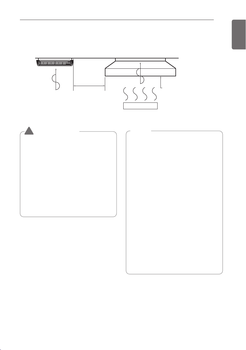
THE INDOOR UNIT INSTALLATION
Air conditioner
Take enough
distance
Cooking table
Use the ventilation fan
for smoke-collecting
hood with sufficient
capacity.
23
ENGLISH
CAUTION
!
• This air-conditioner uses a drain pump.
• Install the unit horizontally using a level
gauge.
• During the installation, care should be
taken not to damage electric wires.
• Select and mark the position for fixing
bolts and piping hole.
• Decide the position for fixing bolts
slightly tilted to the drain direction after
considering the direction of drain hose.
• Drill the hole for anchor bolt on the
ceiling or wall.
NOTE
• Avoid the following installation location.
1. Such places as restaurants and kitchen
where considerable amount of oil
steam and flour is generated.
These may cause heat exchange
efficiency reduction, or water drops,
drain pump mal-function.
In these cases, take the following
actions;
• Make sure that ventilation fan is enough
to cover all noxious gases from this
place.
• Ensure enough distance from the
cooking room to install the air
conditioner in such a place where it may
not suck oily steam.
2. Avoid installing air conditioner in such
places where cooking oil or iron
powder is generated.
3. Avoid places where inflammable gas is
generated.
4. Avoid place where noxious gas is
generated.
5. Avoid places near high frequency
generators.
Install the unit leaning to a drainage hole side
as a figure for easy water drainage.

24
C
E
G
D
F
I
A
J
B
H
Drainage hole
C
E
G
D
A
J
B
Drainage hole
F
I
H
Inspection Port
Indoor Unit
Ceiling
Canvas Duct
Air Intake Port
Ceiling Board
Ceiling Board
Air Discharge Port
Discharge
Flexible Duct
Intake
Duct
Inspection Port
Indoor Unit
Ceiling
Canvas Duct
Air Intake Port
Ceiling Board
Ceiling Board
Air Discharge Port
Discharge
Flexible Duct
Intake
Duct
ENGLISH
THE INDOOR UNIT INSTALLATION
Position of suspension Bolt
- Apply a joint-canvas between the unit and
duct to absorb unnecessary vibration.
- Apply a filter Accessory at air return hole.
[Ceiling Concealed Duct – Low Static]
(Unit: mm)
[Ceiling Concealed Duct – Mid Static]
(Unit: mm)
Dimension
Chassis
Mid
Static
A B C D E F G H I J
M1 933.4 971.6 619.2 700 30 270 15.2 858 201.4 900
M2 1 283.41 321.6 619.2 689.6 30 270 15.2 1 208 201.4 1 250
M3 1 283.41 321.6 619.2 689.6 30 360 15.2 1 208 291.4 1 250
Dimension
A B C D E F G H I J
Chassis
L1 733 772 628 700 36 190 20 660 155 700
L2 933 972 628 700 36 190 20 860 155 900
L3 1133 1172 628 700 36 190 20 1060 155 1100
Low
Static
L4 733 772 338 460 36 190 20 660 148 700
L5 933 972 338 460 36 190 20 860 148 900
L6 1133 1172 338 460 36 190 20 1060 148 1100

THE INDOOR UNIT INSTALLATION
1 Set anchor
Old building New building
2 Plate washer
3 Spring washer
4 Nut
5 Suspension
bolts
25
ENGLISH
- A place where the unit will be leveled and
that can support the weight of the unit.
- A place where the unit can withstand its
vibration.
- A place where service can be easily
performed.
M10 Nut
M10 SP. washer
M10 washer
M10 washer
M10 SP. washer
M10 Nut
- Select and mark the position for fixing bolts.
- Drill the hole for set anchor on the face of
ceiling.
X 4
X 4
X 4
X 4
X 4
X 4
(Local
supply)
(Local
supply)
- Insert the set anchor and washer onto the
suspension bolts for locking the suspension
bolts on the ceiling.
- Mount the suspension bolts to the set
anchor firmly.
- Secure the installation plates onto the
suspension bolts (adjust level roughly) using
nuts, washers and spring washers.
• Local supply
① Set anchor
② Plate washer - M10
③ Spring washer - M10
④ Nut - W3/8 or M10
⑤ Suspension bolt - W3/8 or M10
CAUTION
!
• Tighten the nut and bolt to prevent unit
falling.
CAUTION
!
1. Install declination of the indoor unit is
very important for the drain of the duct
type air conditioner.
2. Minimum thickness of the insulation for
the connecting pipe shall be 10 mm.

26
ENGLISH
THE INDOOR UNIT INSTALLATION
Front of view
- The unit must be horizontal or declined to
the drain hose connected when finished
installation.
Ceiling
Drain Pump use
Drainage hole
Ceiling Concealed Duct – Low static
- The unit must be declined to the drain hose
connected when finished installation.
CORRECT
5~10 mm
Drainage hole
INCORRECT
[Ceiling Cassette]
Ceiling
TP/TN/TM Series
875(Ceiling opening)
787(Hanging bolt)
840 Unit size
671
TQ/TR Series
585~660
517
840 Unit size
Level gauge
Ceiling board
(Hanging bolt)
684
875(Ceiling opening)
Unit:mm
Drainage hole
Ceiling Concealed Duct – Mid static
400 4040
523
600
306
50
250
570
570
319
461
TU Chassis
1 065
860
965
448
517
585~660
Unit:mm
50
354
466

THE INDOOR UNIT INSTALLATION
Flat washer for M10
(accessory)
Flat washer for M10
(accessory)
Hanging bolt
(W3/8 or M10)
Nut
(W3/8 or M10)
Nut
(W3/8 or M10)
Spring washer
(M10)
Set screw of
paper model (4 pieces)
Paper model
for installation
Ceiling
board
150 mm
Ceiling board
Ceiling
Keep the length of the bolt
from the bracket to 40 mm
Open the ceiling board
along the outer edge of the
paper model
Air Conditioner body
Keep the length of 15~18 mm
between the air conditioner
bottom surface and the ceiling
surface
Adjust the
same height
Set screw of
paper model (4 pieces)
Paper model
for installation
70 mm
Adjust the same height
Ceiling board
Ceiling
Keep the length of the bolt
from the bracket to 40 mm
Open the ceiling board
along the outer edge of the
paper model
Air conditioner body
Keep the length of 20~22 mm
between the air conditioner bottom
surface and the ceiling surface
4Way
1Way
Ceiling boardCeiling boardCeiling board
27
ENGLISH
The following parts is option.
① Hanging Bolt - W 3/8 or M10
② Nut - W 3/8 or M10
③ Spring Washer - M10
④ Plate Washer - M10
Drill the piping hole on the wall slightly tilted
to the outdoor side using a Ø 70 hole-core
drill.
CAUTION
!
Tighten the nut and bolt to prevent unit
falling.
Wall
Indoor
Outdoor
5~7 mm

28
86
c
d
160
213
Framework of Indoor Unit
(Unit: mm)
131
C Type: 494 C Type: 504
Place a level on raised tab
Unit Outline
83
C Type: 134
Measuring Tape
Ø 65
83
Measuring Tape
Hanger
Ø 65
C Type: 150
(Unit : mm)
Right rear piping
Left rear piping
(Unit : mm)
194152
Ø 65
Right rear piping
Left rear piping
Ø 65
C Type : 134C Type : 98
C Type
C Type : 418 C Type : 418
Place a level on raised tab
Unit Outline
Installation Plate
ENGLISH
THE INDOOR UNIT INSTALLATION
Fixing Installation Plate
[Wall Mounted]
The wall you select should be strong and solid
enough to prevent vibration
1 Mount the installation plate on the wall
with type "A" screws. If mounting the unit
on a concrete wall, use anchor bolts.
- Mount the installation plate horizontally
by aligning the centerline using Horizontal
meter.
SK/SJ Chassis
2 Measure the wall and mark the centerline.
It is also important to use caution
concerning the location of the installation
plate. Routing of the wiring to power
outlets is through the walls typically.
Drilling the hole through the wall for piping
connections must be done safely.
SK/SJ Chassis
SR Chassis
SR Chassis

THE INDOOR UNIT INSTALLATION
29
ENGLISH
Connecting the Piping
1 Pull the cover at the bottom of the indoor
unit. Pull the cover ①→②.
2 Remove the cover from the indoor unit.
3 Pull back the tubing holder.
4 Remove pipe port cover and positioning
the tubing
Indoor unit back side view
Right
Tubing holder
Left
Backwards
Assembly of chassis cover
1 Insert 4 hooks of the chassis cover into
gap of the chassis certainly.
2 Push the 6 point hook to assemble chassis
cover. Push the chassis cover ①→②.
* The feature can be changed according to
type of model.
NOTE
To protect the chassis cover bended,
assembly chassis cover correctly.

30
ENGLISH
THE INDOOR UNIT INSTALLATION
Good case
- Press on the tubing cover and unfold the
tubing to downward slowly. And then bend
to the left side slowly.
* The feature can be changed according to
type of model.
Bad case
- Following bending case from right to left
directly may cause damage to the tubing.
NOTE
Installation Information. For right piping.
Follow the instruction above.
Installation of Indoor Unit
1 Hook the indoor unit onto the upper
portion of the installation plate.( engage
the three hooks at the top of the indoor
unit with the upper edge of the installation
plate) Ensure that the hooks are properly
seated on the installation plate by moving
it left and right
Installation plate
2 Unlock the tubing holder from the chassis
and mount between the chassis and
installation plate in order to separate the
bottom side of the indoor unit from the
wall.
* The feature can be changed according to
type of model.
Tubing Holder
*
The feature can be changed according to the
type of model.

THE INDOOR UNIT INSTALLATION
31
ENGLISH
Piping
1 Insert the connecting cable through the
bottom side of indoor unit and connect the
cable (You can see detail contents in
'Connecting the cables' section)
<Left side piping>
View
1(L) 2(N) 3(C)
<Left side piping>
Slide up the metal
plate cover
Terminal block
Connecting cable
Cable retainer
<Right side piping>
1(L) 2(N) 3(C)
<Right side piping>
View
Connecting
cable
Slide up the metal
plate cover
Terminal block
Connecting cable
Cable retainer
Tape
Drain hose
Connecting pipe
Drain hose
Tape
Connecting
cable
Drain hose
Connecting pipe
2 Secure the cable onto the control board
with the cable retainer.
3 Tape the tubing pipe, drain hose and the
connection cable. Be sure that the drain
hose is located at the lowest side of the
bundle. Locating at the upper side can
cause overflow from the drain pan through
the inside of the unit.

32
ENGLISH
THE INDOOR UNIT INSTALLATION
Finishing the indoor unit
installation
1 Mount the tubing holder in the original
position.
2 Ensure that the hooks are properly seated
on the installation plate by moving it left
and right.
3 Press the lower left and right sides of the
unit against the installation plate until the
hooks engage into their slots (clicking
sound).
4 Finish the assembly by screwing the unit
to the installation plate by using two
pieces of type "C" screws. And assemble a
chassis cover.
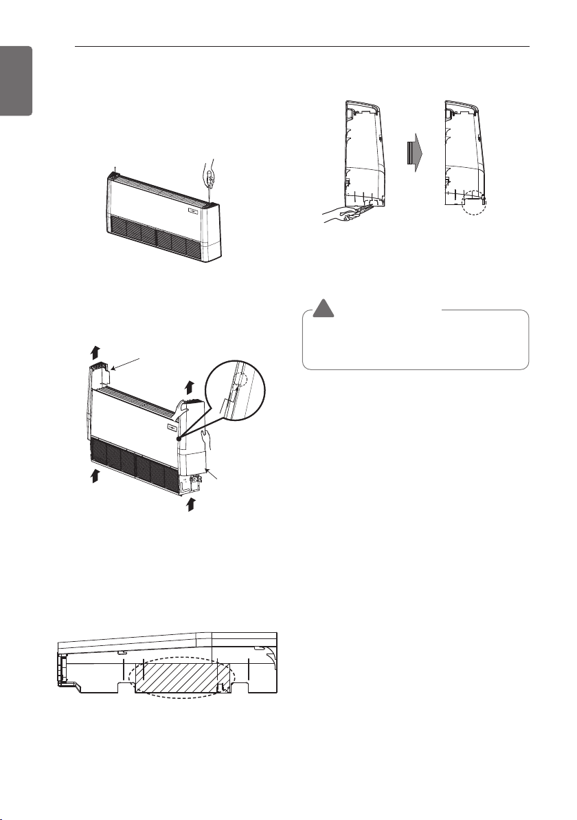
[Console]
Preparation / Removing front panel
1 Open the front grille by pulling forward
2 Then pull out the link of grille from groove
in front panel.
3 Then pull out 2 hinges of grille from
grooves in front panel.
4 Then remove 4 screws, dismount the front
panel while pulling it forward.
Type 'C' screw
* The feature can be changed according to
type of model.
CAUTION
!
The indoor unit can be dropped from the
wall, the indoor unit is not screwed
correct position on the install plate.
To avoid the gap between the indoor unit
and wall , screw the indoor unit to the
install plate correctly.

THE INDOOR UNIT INSTALLATION
Remove
Upper
Deco cover
Side
Deco cover
45
90 75
Left bottom
piping
Right bottom
piping
Left/right piping
Right back piping
60
40
50
Wall
45
90
75
Left back
piping
Right back
piping
45
33
ENGLISH
Preparation / For Moldings , Side
Piping, and Concealed Installation
For Moldings
1 Remove the slit portions on the Rear
Panel.
For Concealed Installation
1 Remove the 6 screws.
2 Remove the Upper Deco cover.
3 Remove the Side Deco covers.
Refrigerant Piping
1 The location of hole is different depending
on which side of the pipe is taken out.
2 Drill a hole (Ø 70 mm)in the point indicated
by symbol in the illustration as below
(Unit: mm)
For Side Piping
1 Remove the Deco Covers.
2 Remove the slit portions
3 Assemble the Deco Covers.
NOTE
The suggested shortest pipe length is
5 m, in order to avoid noise from the
outdoor unit and vibration.

THE INDOOR UNIT INSTALLATION
600
Ø17
103
87
Installation Plate
Molding
4 screw (M*25L)
6 screw (M*25L)
64
159
(700)
26
647
180
140
(600)
574
170
170
210
30.5
30.5
140
160
34
ENGLISH
1 The Outer diameter of Drain Hose (which is supplied with indoor unit) is 17 mm at connecting
end, 600 mm long.
2 Use commercial rigid PVC pipe for extension.
3 Insulate the indoor drain pipe with 10 mm or more of insulation material to prevent
condensation.
(Unit: mm)
NOTE
The drain pipe should be inclined downward so that water will flow smoothly without any
accumulation.
Installing Indoor unit
Installation on the Floor
1 Fix up using 6 screws for floor installation.
(Unit: mm)
Installation on the Wall
1 Fix up the installation plate using 5 screws and the indoor unit using 4 screws.
2 The installation plate should be fixed on a wall which can support the weight of the indoor
unit.

Half concealed installation.
647
170
140
170
140
Screw hole
Screw hole
Fixing point
on the back
Supplemental plate
(Field supply)
Opening hole
Wall
Wall
75
50
35
75
Left bottom piping
Left piping
45
50
Right bottom piping
1 Make a wall hole of the size shown Fig-1.
Wall
670
Hole
45
Supplemental plate
(Field supply)
THE INDOOR UNIT INSTALLATION
(Unit: mm)
95
Supplemental plate
(Field supply)
35
ENGLISH
200
585
150
<Fig - 1>
2
Installation of supplemental plate for attaching main unit.
1) Normal concealed 2) Deep concealed
200
150
• The rear of the unit can be fixed with screws at the points shown in the Fig-2. Be sure to install
the supplemental plate in accordance with the depth of the inner wall.
(Unit: mm)
3
Piping Hole
(Unit: mm)

THE INDOOR UNIT INSTALLATION
36
ENGLISH
4 Remove the Deco Covers and Fixing Indoor Unit
1) Remove the Deco Covers.
2) Insert the Indoor Unit to the Wall hole.
3) Secure using 6 screws. (shown in the illustration)
NOTE
Check the horizon of Indoor unit with the wall. Please use the Leveler on the drain pan guide.
Leveler
Drain pan
Less than 5 mm
Less than 5 mm Less than 5 mm

THE INDOOR UNIT INSTALLATION
Connecting the Piping
When you connect the refrigerant pipe, it is easier that you connect the gas pipe first.
1 Hold up the Sensor Link.
2 Separate the Pipe Bracket (2 screws)
3 Connect the refrigerant pipe.
4 Assemble the Pipe Bracket (2 screws)
5 Put down the Sensor Link
37
ENGLISH
12
45
3
6 After connecting, check the pipe arrangement as per illustration.
7 The piping can be arranged in six ways as shown in the illustration below.
Pipe Guide
Connecting Pipe
Pipe Guide
Connecting Pipe must be placed inner
than the pipe guide.
3
2
1
4
6
5
38
Backside
Right side cover
Backside
Left side
cover
ENGLISH
THE INDOOR UNIT INSTALLATION
Open side-cover
[Ceiling suspended type]
Step 1
- Remove two screws from side-cover.
Step 2
Step 4
- Knock out the pipe hole from the left
sidecover with nipper/plier.
CAUTION
!
Hold the side-cover with other hand while
tapping to prevent it to fall down.
- Unlock side-cover from side-panel slightly
(Tap the side-cover with your palm on the
backside)
Step 3
- Remove paper bracket from side-cover.

THE INDOOR UNIT INSTALLATION
Washer
Suspension
bolts
Suspension bol
39
ENGLISH
Mounting the anchor nut and
bolt
- Prepare 4 suspension bolts. (Each bolts
length should be same.)
- Measure and mark the position for the
Suspension bolts and the piping hole.
- Drill the hole for anchor nut on the ceiling.
- Insert the nuts and washer onto the
suspension bolts for locking the suspension
bolts on the ceiling.
- Mount the suspension bolts to the
anchornuts firmly.
- Secure the hangers onto the Suspension
bolts (adjust level roughly.) using nuts,
washers and spring washers.
- Adjust a level with a level gauge on the
direction of left-right, back-forth by adjusting
suspension bolts.
- Adjust a level on the direction of top-bottom
by adjusting suspension bolts. Then the unit
will be declined to the bottomside so as to
drain well.
(Unit : mm)
Model (kBtu/h) A B
18 k/24 k 1 018
36 k/42 k/48 k/60 k 1 418
355
Anchor nut
Ceiling
Nut
Suspension
Suspension
bolts
bolts
!
Installation information for declination
- Install declination of the indoor unit is
very important for the drain of the
convertible type air conditioner.
- Minimum thickness of the insulation
for the connecting pipe shall be 10
mm.
- If the Installation Plates are fixed to
horizontal line, the indoor unit after
installing will be declined to the
bottomside.
Washer
Washer
A
Suspension bol
Suspension bol
Hangen
CAUTION
Suspension
bolts
Spring
washer
Max.
12 mm
t
B
Nut
Washer

THE INDOOR UNIT INSTALLATION
Ceiling
10~20 mm
Ceiling
5~10 mm
40
ENGLISH
Front of view
- The unit must be horizontal or inclined at angle.
- The inclination should be less than or equal to 1° or in between 10 to 20 mm inclined in drain
direction as shown in fig.
Side of view
- The unit must be inclined to the bottomside of the unit when finished installation.

THE INDOOR UNIT INSTALLATION
Maintenance
drain port
Upward
routing
not allowed
Pipe clamp
Indoor unit
700 or less
1 -1.5 m
Clamp metal(attached) Drain hose(attached)
Drain raising pipe
300 mm or less300 mm or less300 mm or less
41
ENGLISH
Indoor Unit Drain Piping
[Ceiling Concealed Duct / Cassette]
- Drain piping must have down-slope (1/50 to
1/100): be sure not to provide up-and-down
slope to prevent reversal flow.
- During drain piping connection, be careful
not to exert extra force on the drain port on
the indoor unit.
- The outside diameter of the drain connection
on the indoor unit is 32 mm.
Piping material: Polyvinyl chloride pipe VP25 and pipe fittings
- Be sure to execute heat insulation on the
drain piping.
- Install the drain raising pipes at a right
angle to the indoor unit and no more than
300 mm from the unit.
Drain test
The air conditioner uses a drain pump to
drain water.
Use the following procedure to test the
drain pump operation:
- Connect the main drain pipe to the exterior
and leave it provisionally until the test
comes to an end.
- Feed water to the flexible drain hose and
check the piping for leakage.
- Be sure to check the drain pump for
normal operating and noise when electrical
wiring is complete.
- When the test is complete, connect the
flexible drain hose to the drain port on the
indoor unit.
Feed water
Flexible drain hose
(accessory)
Main drain pipe
Drain
Drain Pump
Glue the joint
port
Drain hose connection
Use the clip (accessory)
Drain pan
CAUTION
!
The supplied flexible drain hose should not
be curved, neither screwed. The curved or
screwed hose may cause a leakage of
water.
Heat insulation material: Polyethylene
foam with thickness more than 8 mm.
Max 300 mm
Metal
clamp
Flexible drain hose
Insulation
Hanger
distance
1~1.5 m
Hanger Bracket
1/50~1/100 slope
Max 700 mm

42
Do not raise
Water
leakage
Tip of drain hose
dipped in water
Water
leakage
Ditch
Less than
50 mm gap
Accumulated
drain water
Air
Waving
Water
leakage
Downward slope
ENGLISH
THE INDOOR UNIT INSTALLATION
[Wall Mounted]
To check the drainage
1 Pour a glass of water on the evaporator.
2 Ensure the water flows through the drain
hose of the indoor unit without any
leakage and goes out the drain exit.
Connecting area
drain hose
Leakage
checking
Drain pan
Drain
hose
Leakage
checking
* The feature can be changed according to
type of model.
Drain piping
1 The drain hose should point downward for
easy drain flow.
2 Do not make drain piping like the
following.
* The feature can be changed according to
type of model.
Evaluation of the performance
Operate the unit for 15~20 minutes, then
check the system refrigerant charge:
1 Measure the pressure of the gas side
service valve.
2 Measure the air temperature from inlet and
outlet of air conditioner.
3 Ensure the difference between the inlet
and outlet temperature is more than 8 °C.
4 For reference; the gas side pressure at
optimum condition is shown on table
(cooling)
The air conditioner is now ready to use.
Inlet temperature
Discharge air
Discharge
temperature
* The feature can be changed according a
type of model.

THE INDOOR UNIT INSTALLATION
Drain hose
Bracket
43
ENGLISH
[Ceiling suspended type]
- Drain piping must have down-slope (1/50 to
1/100): be sure not to provide up - and down slope to prevent reversal flow.
- During drain piping connection, be careful
not to exert extra force on the drain port on
the indoor unit.
- Remove the rubber stopple before
connecting drain hose.
- Hook on the bracket after connecting the
drain hose as below.
Drain test
Use the following procedure to test the drain
pump operation:
- Set the air direction louvers up - and - down
to the position(horizontally) by hand.
- Pour a glass of water on the evaporator
using a kettle.
- Ensure the water flows through the drain
hose of the indoor unit without any leakage
and goes out the drain exit.

THE INDOOR UNIT INSTALLATION
44
ENGLISH
HEAT INSULATION
- Use the heat insulation material for the refrigerant piping which has an excellent heat-resistance
(over 120 °C).
- Precautions in high humidity circumstance:
This air conditioner has been tested according to the "KS Standard Conditions with Mist" and
confirmed that there is not any default. However, if it is operated for a long time in high humid
atmosphere (dew point temperature: more than 23 °C), water drops are liable to fall. In this case,
add heat insulation material according to the following procedure:
Fastening band
(accessory)
Indoor
unit
Refrigerant
piping
Thermal insulator
(accessory)
- Heat insulation material to be prepared... Adiabatic EPDM or NBR with thickness 10 to 20 mm.
- Stick glass wool on all air conditioners that are located in ceiling atmosphere.
Insulation material standard (mm) - residential
If installed in an air-conditioned
place (CASE 1)
(ex: bedroom, living room, etc.)
13
13
13
13
13
13
19
19
19
19
19
If installed in a non-air
conditioned place (CASE 2)
(ex: hallway, outdoors, etc.)
19
19
19
19
19
19
19
19
19
25
25
Insulation material
standard (mm)
(unfavorable
conditions)
19
25
25
25
25
32
32
32
32
32
32
applies to
Gas piping
Liquid
piping
Insulation material standard
(mm)
(besides normal conditions for
residential use)
Refrigerant piping
dimensions (mm)
6.35
9.52
12.7
15.88
19.05
22.22
25.40
28.58
31.75
38.1
44.45
6.35
9.52
EPDM EPDM EPDM EPDM
19
19
19
19
19
19
19
19
19
25
25
9 9 9 9
12.7~44.45 13 13 13 13
• Normal conditions: Temperature of 30 °C, relative humidity of 85 %
• Unfavorable conditions: Temperature of 30 °C, relative humidity of 90 % (humid places such as
bathrooms, swimming pools, etc.: air supply and exhaust fan installation)

THE INDOOR UNIT INSTALLATION
Power
connecting cable
Control box
Control box cover
(On which the Electric
Wiring Connection is put)
1
1
Control terminal board
Remote controller cord
Connection cord between the indoor
unit and the outdoor unit
Ceiling Concealed Duct – Low Static, Mid Static
Remote
controller
cord
1
1
Connection
cord
between the
indoor unit and
the outdoor
unit
Control box cover
(On which the
Electric Wiring
Connection is put)
45
ENGLISH
Wiring Connection
* The feature can be changed according a
type of model.
- Open the control box cover and connect the
Remote controller cord and Indoor power
wires.
- Remove the control box cover for electrical
connection between the indoor and outdoor
unit. (Remove screws ①)
- Use the cord clamper to fix the cord.
Connect the cable to the indoor unit by
connecting the wires to the terminals on the
control board individually according to the
outdoor unit connection. (Ensure that the color
of the wires of the outdoor unit and the
terminal No. are the same as those of the
indoor unit.)
Insert the connecting cable through the bottom side of indoor unit and connect the cable.
(1) Open the Decor
(2) Unscrew the screw of C/Box
(3) Slide up the Metal Plate Cover
(4) Connect the connecting cable
(5) After complete connect the cables, should
assemble the Metal Plate Cover by screw.
1(L) 2(N) 3(C)
Decor
Power
Power
connecting cable
connecting cable
1
Loosen No 1, 2 screws of control box
cover.
2
Connect the cable to the Terminal block as
below diagram
Terminal Block of Indoor Unit
1(L) 2(N) 3
Outdoor

46
1
3
2
Connecting Cable
Clamp Cord
Terminal Block
ENGLISH
THE INDOOR UNIT INSTALLATION
1
3
2
CAUTION
!
The connecting cable connected to the
indoor and outdoor unit should be
complied with the following specifications
(This equipment shall be provided with a
cord set complying with the national
regulation).
10±3 mm
35±5 mm
GN/YL
NORMAL
CROSS-SECTIONAL
AREA 0.75 mm
20 mm
2
3
Secure the cable onto the Control panel
with the Clamp cord.
4
If indoor unit's setting is needed, loosen
No.3 screw and lift up the PCB. (option:
usage of bottom vanes, limit angle of top
vane)
DIP
Description
S/W
S/W 5
S/W 7 Vane
The Power cord connected to the unit
should be selected according to the
following specifications.
Install
scene
CAUTION
!
S/W OFF S/W ON
Exposed
Top+Bottom
vane
Concealed
Top vane
Half
only
If the supply cord is damaged, it must be
replaced by a special cord or assembly
available from the manufacturer of its
service agent.
CAUTION
!
- The circuit diagram is a subject to
change without notice.
- The earth wire should be longer than the
common wires.
- When installing, refer to the circuit
diagram on the chassis cover.
- Connect the wires firmly so that they
may not be pulled out easily.
- Connect the wires according to color
codes, referring to the wiring diagram.

THE INDOOR UNIT INSTALLATION
Power wire
Round pressure terminal
Connect same thickness
wiring to both sides.
It is forbidden to
connect two to one
side.
It is forbidden to
connect wiring of
different thicknesses.
47
ENGLISH
Precautions when laying power
wiring
Use round pressure terminals for connections
to the power terminal block.
When none are available, follow the
instructions below.
- Do not connect wiring of different
thicknesses to the power terminal block.
(Slack in the power wiring may cause
abnormal heat.)
- When connecting wiring which is the same
thickness, do as shown in the figure below.
- For wiring, use the designated power wire
and connect firmly, then secure to prevent
outside pressure being exerted on the
terminal block.
- Use an appropriate screwdriver for tightening
the terminal screws. A screwdriver with a
small head will strip the head and make
proper tightening impossible.
- Over-tightening the terminal screws may
break them.
CAUTION
!
According to the confirmation of the above
conditions, prepare the wiring as follows.
1 Never fail to have an individual power
circuit specifically for the air conditioner.
As for the method of wiring, be guided
by the circuit diagram posted on the
inside of control cover.
2 The screw which fasten the wiring in the
casing of electrical fittings are liable to
come loose from vibrations to which the
unit is subjected during the course of
transportation. Check them and make
sure that they are all tightly fastened. (If
they are loose, it could cause burn-out of
the wires.)
3 Specification of power source.
4 Confirm that electrical capacity is
sufficient.
5 See that the starting voltage is
maintained at more than 90 percent of
the rated voltage marked on the name
plate.
6 Confirm that the cable thickness is as
specified in the power source
specification. (Particularly note the
relation between cable length and
thickness.)
7 Always install an earth leakage circuit
breaker in a wet or moist area.
8 The following would be caused by
voltage drop.
- Vibration of a magnetic switch, which
will damage the contact point, fuse
breaking, disturbance of the normal
function of the overload.
9 The means for disconnection from a
power supply shall be incorporated in the
fixed wiring and have an air gap contact
separation of at least 3 mm in each
active(phase) conductors.
10 Open the terminal cover block before
connecting the indoor side wire.

48
Pipe
Reamer
Point down
ENGLISH
THE INDOOR UNIT INSTALLATION
Electrical Wiring
1
All wiring must comply with LOCAL
REGULATIONS.
2
Select a power source that is capable of
supplying the current required by the air
conditioner.
3
Feed the power source to the unit via a
distribution switch board designed for this
purpose.
4
The terminal screws inside the control box
may be loose due to vibration during
transport.
Check the screws for loose connection.
(Running the air conditioner with loose
connection can overload and damage
electrical components.)
5
Always ground the air conditioner with a
grounding wire and connector to meet the
LOCAL REGULATION.
Main power source
Air
Conditioner
CAUTION
!
• The circuit diagram is not subject to
change without notice.
• Be sure to connect wires according to
the wiring diagram.
• Connect the wires firmly, so that not to
be pulled out easily.
• Connect the wires according to color
codes by referring the wiring diagram.
Circuit Breaker
Flaring Work
Main cause for gas leakage is due to defect of
flaring work. Carry out correct flaring work in
the following procedure.
Cut the pipes and the cable
1 Use the piping kit accessory or the pipes
purchased locally.
2 Measure the distance between the indoor
and the outdoor unit.
3 Cut the pipes a little longer than measured
distance.
4 Cut the cable 1.5 m longer than the pipe
length.
Copper
pipe
Burrs removal
1. Completely remove all burrs from the cut
cross section of pipe/tube.
2. While removing burrs put the end of the
copper tube/pipe in a downward direction
while removing burrs location is also
changed in order to avoid dropping burrs
into the tubing.
90°
Slanted Uneven Rough
CAUTION
!
Copper in contact with refrigerants shall be
oxygen-free or de-oxidized, for example
Cu-DHP as specified in EN 12735-1 and
EN 12735-2

THE INDOOR UNIT INSTALLATION
Flare nut
Copper tube
49
ENGLISH
Putting nut on
- Remove flare nuts attached to indoor and
outdoor unit, then put them on pipe/tube
having completed burr removal. (not possible
to put them on after finishing flare work)
Flaring work
1
Firmly hold copper pipe in a bar with the
dimension shown in below table table
below.
2 Carry out flaring work with the flaring tool.
Pipe diameter
Inch (mm)
Ø 1/4 (Ø 6.35)
Ø 3/8 (Ø 9.52)
Ø 1/2 (Ø 12.7)
Ø 5/8 (Ø 15.88)
Ø 3/4 (Ø 19.05)
0.04~0.05 (1.1~1.3)
0.06~0.07 (1.5~1.7)
0.06~0.07 (1.6~1.8)
0.06~0.07 (1.6~1.8)
0.07~0.08 (1.9~2.1)
A inch (mm)
Wing nut type Clutch type
0~0.02
(0~0.5)
CAUTION
!
• The installation of pipe-work shall be
kept to a minimum
• Flared joint shall be restricted to use
with annealed pipe only, and to pipe
sizes not exceeding a diameter of 20
mm outside diameter.
Check
1 Compare the flared work with the figure
by.
2 If a flared section is defective, cut it off
and do flaring work again.
Smooth all round
Even length
all round
Inside is shiny without scratches
= Improper flaring =
Surface
damaged
Cracked Uneven
Inclined
thickness
Bar
Copper pipe
<Wing nut type>
"A"
<Clutch type>

50
Gas Pipe
Liquid Pipe
Cutting Line
Cutting Line
Good Case Bad Case
* Tubing cutting line have to be upward.
Vinyl tape(narrow)
Connection pipe
Connecting cable
Vinyl tape (wide)
Wrap with vinyl tape
Indoor unit pipe
Pipe
ENGLISH
THE INDOOR UNIT INSTALLATION
Connecting the installation pipe and
drain hose to the indoor unit.
1 Align the center of the pipes and
sufficiently tighten the flare nut by hand
Indoor unit tubing Flare nut Pipes
2 Tighten the flare nut with a wrench
Outside diameter
mm inch kgf.m
Ø 6.35 1/4 1.8~2.5
Ø 9.52 3/8 3.4~4.2
Ø 12.7 1/2 5.5~6.5
Ø 15.88 5/8 6.3~8.2
Ø 19.05 3/4 9.9~12.1
Wrench
Torque
Open-end wrench
(fixed)
Flare nut
Connection
pipe
Wrap the insulation material around
the connecting portion.
1 Overlap the connection pipe insulation
material and the indoor unit pipe insulation
material. Bind them together with vinyl
tape so that there may be no gap.
Insulation material
2 Set the tubing cutting line upward.
Wrap the area which accommodates the
rear piping housing section with vinyl tape.
Indoor unit tubing
CAUTION
!
• When mechanical connectors are reused
indoors, sealing parts shall be renewed.
• When flared joints are reused indoors,
the flare part shall be re-fabricated.
3 When needed to extend the drain hose of
indoor unit, assembly the drain pipe as
shown on the drawing
Drain pipe
Adhesive
Indoor unit drain hose
Vinyl tape(narrow)
3 Bundle the piping and drain hose together
by wrapping them with vinyl tape sufficient
enough to cover where they fit into the
rear piping housing section.
Wrap with vinyl tape
Pipe
Vinyl tape(wide)
Drain hose

THE INDOOR UNIT INSTALLATION
51
ENGLISH
Test Running
- Check that all tubing and wiring are properly
connected.
- Check that the gas and liquid side service
valves are fully open.
Prepare remote controller
1 Remove the battery cover by pulling it
according to the arrow direction.
2 Insert new batteries making sure that the
(+) and (–) of battery are installed correctly.
3 Reattach the cover by pushing it back into
position.
NOTE
Test operation
- If you press and hold the On/Off button for
3 – 5 seconds instead of 6 seconds, the unit
will switch to the test operation.
- In the test operation, the unit blows out
strong air for cooling for 18 minutes and then
returns to the factory default settings.
NOTE
If the actual pressure is higher than shown,
the system is most likely over-charged, and
charge should be removed. If the actual
pressure are lower than shown, the system
is most likely undercharged, and charge
should be added.
• Use 2 AAA(1.5 V) batteries. Do not use
rechargeable batteries.
• Remove the batteries from the remote
controller if the system is not used for
a long time

THE INDOOR UNIT INSTALLATION
52
ENGLISH
Pump Down
This is performed when the unit is relocated
or the refrigerant circuit is serviced.
Pump Down means collecting all refrigerant into
the outdoor unit without the loss of refrigerant.
NOTE
Be sure to perform Pump Down procedure
in the cooling mode.
WARNING
!
It may cause explosion or injury.
After pump down, power must be turned
off before removing the pipe. When
operating this product without connecting
the pipe, there will be high pressure inside
the compressor due to the entry of air,
possibly causing explosion or injury.
Pump Down Procedure
- Connect a low-pressure gauge manifold
hose to the charge port on the gas side
service valve.
- Open the gas side service valve halfway and
purge the air in the manifold hose using the
refrigerant.
- Close the liquid side service valve(all the
way).
- Turn on the unit's operating switch and start
the cooling operation.
- When the low-pressure gauge reading
becomes 1 to 0.5 kg/cm
P.S.I.G.), fully close the gas side valve and
then quickly turn off the unit. Now Pump
Down procedure is completed, and all
refrigerant is collected into the outdoor unit.
2
G(14.2 to 7.1

THE INDOOR UNIT INSTALLATION
53
ENGLISH
Heating Only Mode
Heating Only Mode switching
function setup
1 Supply the power to the unit with no
functions active.
2 Enter the Installer Code and set the code
to 47.
3 Press to select the code No.47 then,
check if buzzer beeps.
4 Cut the power to the unit.
5 Turn back on the power to the unit after 30
seconds.
Heating Only Mode switching
function disable setup
1 Supply the power to the unit with no
functions active.
2 Enter the Installer Code and set the code
to 48.
3 Press to select the code No.48 then,
check if buzzer beeps.
4 Cut the power to the unit.
5 Turn back on the power to the unit after 30
seconds.
* How to enter the installer mode
Press Reset Button and ‘A’ Button ( )
Press
* How to set the code
Set the code you want by pressing TEMP
button ( _
) and press .
_
SETUP
10 digit
1 digit
NOTE
A
- Once the function is set up, Cooling,
Dehumidification Auto Change over
cannot be used.
- Once the function is disable it will
return to its normal state.
- Code cannot be entered when it is in
operation mode. It must be OFF state
to enter code.
- Even if able to enter code in ON state,
it won’t function if the code is not
entered in OFF state.
- At Heating Only Mode, if the product
gets turned off while the wireless
remote control is set at other than
heating / blowing, the product will not
get turned back on. Turn off the
product after the wireless remote
control is set at heating / blowing and
then turn back on.

54
ENGLISH
THE INDOOR UNIT INSTALLATION
SMART DIAGNOSIS
(Optional)
Diagnosis of operating information
1 Enter the Installer Code and set the code
to 57.
2 Click the “Receive” button on the main
screen of LG AC Smart Diagnosis App on
your smart phone.
3 Press and hold your smart phone close
to the indoor unit.
4 Receive the buzzer beeps from indoor unit
with your smart phone.
5 The diagnosis of operating information will
be displayed on the screen of your smart
phone.
Diagnosis of error information
1 Enter the Installer Code and set the code
to 58.
2 Click the “Receive” button on the main
screen of LG AC Smart Diagnosis App on
your smart phone.
3 Press and hold your smart phone close
to the indoor unit.
4 Receive the buzzer beeps from indoor unit
with your smart phone.
5 The diagnosis of operating information will
be displayed on the screen of your smart
phone.
* How to enter the installer mode
Press Reset Button and ‘A’ Button ( )
Press
* How to set the code
Set the code you want by pressing TEMP
button ( _) and press .
_
SETUP
10 digit
1 digit
NOTE
- Be sure to keep ambient noise to a
minimum or the smart phone may not
correctly receive the buzzer beeps from
the indoor unit.
- Initialization of diagnosis data may take
approximately 1 minute after supplying
the AC power .
- The code No. 57 is used for confirming
the diagnosis data which is updated on
while the indoor unit is operating
- The code No. 58 is used for confirming
the diagnosis data which is the occurred
time of Error Code.
A

THE INDOOR UNIT INSTALLATION
Manual the decor, air filter Assembly & Disassembly
55
ENGLISH
Disassemble the decor
1 Turn off the power and unplug the power cord.
2 Pull the decor at the bottom of the indoor unit.
3
Remove the decor from the indoor unit.
Assemble the decor
1
Turn off the power and unplug the power cord.
2 Insert 3 or 4 hooks of the decor into gap of
the indoor unit certainly.
Disassemble the air filter
1
Turn off the power and unplug the power cord.
2
Hold the knob of the air filter, Lift it up slightly.
3 Hold the knob of the air filter, lift it up
slightly and remove it from the unit.
Assemble the air filter
1
Turn off the power and unplug the power cord.
2 Insert the hooks of the air filter into the
front grille.
3
Push down hooks to assemble the air filter.
3
Push the nooks to assemble the decor.
CAUTION
!
The air filter can be broken when it is
bended.
4 Check side of the front grille for the air filter
assembled correctly.
NOTE
lf the air filter is not assembled correctly, Dust
and other substance come into the indoor unit.
lf look at the indoor unit from higher than it,
can assemble the air filter easily.

THE INDOOR UNIT INSTALLATION
56
ENGLISH
Precautions about installation in regions with extreme snowfall and cold
temperatures
To ensure the outdoor unit operates properly, certain measures are required in locations where there
is a possibility of heavy snowfall or severe wind chill or cold :
1 Prepare for severe winter wind chills and heavy snowfall, even in areas of the country where these
are unusual phenomena.
2 Position the outdoor unit so that its airflow fans are not buried by direct, heavy snowfall.
If snow piles up and blocks the airflow, the system may malfunction.
3 Remove any snow that has accumulated 100 mm or more on the top of the outdoor unit.
4 Place the outdoor unit on a raised platform at least 500 mm higher than the aver- age annual
snowfall for the area. If the frame width is wider than the outdoor unit, snow may accumulate.
5 Install a snow protection hood.
6 To prevent snow and heavy rain from entering the outdoor unit, install the suction and dis- charge
ducts facing away from direct winds.
7 Additionally, the following conditions should be taken into consideration when the unit operates in
defrost mode:
- If the outdoor unit is installed in a highly humid environment (near an ocean, lake, etc.), en- sure
that the site is well-ventilated and has a lot of natural light. (Example: Install on a rooftop.)

INSTALLATION OF DECORATIVE PANEL(ACCESSORY)
Separate the link from the front grill
Corner
cover
Hook
clip
Hook
INSTALLATION OF DECORATIVE PANEL(ACCESSORY)
57
ENGLISH
The decorative panel has its installation
direction.
Before installing the decorative panel,
always remove the paper template.
1 Remove the packing and take out air inlet
grille from front panel.
3 Fit the panel on the unit by inserting hooks
as shown in picture.
4 Insert two screws on diagonal corners of
panel. Do not tighten the bolts completely.
(The fixing screws are included in the
indoor unit box.)
Check the alignment of panel with the
ceiling. Height can be adjusted using
hanging bolts as shown in picture. Insert
the other two screws and tighten all
screws completely.
2 Remove the Corner covers of the panel.

58
Screw
Installing the grill link on the panel body
Inserting the edge into the panel body
Closing the door lock
Check the left, right and central sections
CN_VANE 1,2
CN_DISPLAY
ENGLISH
INSTALLATION OF DECORATIVE PANEL(ACCESSORY)
5 Fit the corner covers.
6 Open two screws of control panel cover.
7 Connect one display connector and two
vane control connectors of front panel to
indoor unit PCB.
The position marking on PCB is as:
Display connector : CN_DISPLAY
Vane control connector: CN_VANE 1,2
9 Install the air inlet grille and Filter on the
panel.
- After inserting the edge of the grill into
the panel body, close the door lock and
press on the left, right, and center
sections.
8 Close the cover for control box.

INSTALLATION OF DECORATIVE PANEL(ACCESSORY)
Air conditioner
unit
Decorative panel
Fit the insulator (this part) and
be careful for cool air leakage
Good example
Ceiling
board
Ceiling
board
Decorative
panel
Air
Cool air leakage
(no good)
Bad example
Air conditioner unit
59
ENGLISH
CAUTION
!
Install certainly the decorative panel.
Cool air leakage causes sweating.
Water drops fall.
PRECAUTIONS IN TEST RUN
- The initial power supply must provide at least
90 % of the rated voltage.
Otherwise, the air conditioner should not be
operated.
CAUTION
!
• For test run, carry out the cooling
operation firstly even during heating
season. If heating operation is carried
out firstly, it leads to the trouble of
compressor. Then attention must be
paid.
• Carry out the test run more than 5
minutes without fail.
(Test run will be cancelled 18 minutes
later automatically)
- To cancel the test run, press any button.
CHECK THE FOLLOWING ITEMS WHEN
INSTALLATION IS COMPLETED
- After completing work, be sure to measure and
record trial run properties, and store measured
data, etc.
- Measuring items are room temperature,
outside temperature, suction temperature,
blow out temperature, wind velocity, wind
volume, voltage, current, presence of abnormal
vibration and noise, operating pressure, piping
temperature, compressive pressure.
- As to the structure and appearance, check
following items.
* Is the circulation of air adequate?
* Is the draining smooth?
* Is the heat insulation complete
(refrigerant and drain piping)?
* Is there any leakage of refrigerant?
* Is the remote controller switch operated?
* Is there any faulty wiring?
* Are not terminal screws loosened?
M4......118 N.cm{12 kgf.cm}
M5......196 N.cm{20 kgf.cm}
M6......245 N.cm{25 kgf.cm}
M8......588 N.cm{60 kgf.cm}
Connection of power supply
- Connect the power supply cord to the
independent power supply.
Circuit breaker is required.
- Operate the unit for 15 minutes or more.
Evaluation of the performance
- Measure the temperature of the intake and
discharge air.
- Ensure the difference between the intake
temperature and the discharge one is more
than 8 °C (Cooling) or reversely (Heating).
Thermometer

60
On/Off
button
0.6 s
1.6 s 4 s
Ex ) CH 132
XXO XOX OXX
ON/OFF
Operation lamp
ENGLISH
INSTALLATION OF DECORATIVE PANEL(ACCESSORY)
Test operation
During the TEST OPERATION, the unit
operates in cooling mode at high speed fan,
regardless of room temperature and resets in
18 minutes. During test operation, if remote
controller signal is received, the unit operates
as remote controller sets. If you want to use
this operation, Press and hold the ON/OFF
button for 3~5 seconds, then the buzzer
sound 1 'beep'. If you want to stop the
operation, re-press the button.
Self-Diagnosis Function
This unit has an inbuilt error diagnosis
capability. Error is displayed by 'RED'
Operation Lamp. Please contact your
serviceman/dealer in such a situation
Evaluation of the performance
Operate the unit for 10~15 minutes, then
check the system refrigerant charge:
1
Measure the pressure of the gas side
service valve.
2
Measure the air temperature from inlet and
outlet of air conditioner.
3
Ensure the difference between the inlet
and outlet temperature is more than 8 °C.
4
For reference; the gas side pressure at
optimum condition is shown on table
(cooling)
The air conditioner is now ready to use.
Intake temperature
Discharge air
Discharge
temperature
Refrigerant
ambient
TEMP.
R-410A 35 °C (95 °F)
Outside
The pressure of
the gas side
8.5~9.5 kg/cm2G
(120~135 P.S.I.G.)
NOTE
If the actual pressure is higher than
shown, the system is most likely overcharged, and charge should be removed. If
the actual pressure are lower than shown,
the system is most likely undercharged,
and charge should be added.

INSTALLATION INSTRUCTIONS
INSTALLATION INSTRUCTIONS
Installer Setting - How to enter installer setting mode
CAUTION
!
Installer setting mode is to set the detail function of the remote controller.
If the installer setting mode is not set correctly, it can cause problems to the product, user
injury or property damage. This must be set by an certificated installer, and any installation or
change that is carried out by a non-certificated person should be responsible for the results.
In this case, free service cannot be provided.
1 With the JET MODE button pressed, press
the RESET button.
2 By using the TEMPERATURE SETTING
button, set function code and setting value.
(Please refer the Installer Setting Code
Table.)
3 Press the ON/OFF button toward the indoor
unit 1 time.
61
ENGLISH
TIME (3 s)
°C/°F (5 s)
4 Reset the remote controller to use the
general operation mode.
Refer to the Installer Setting Code Table
on the next page.

INSTALLATION INSTRUCTIONS
62
ENGLISH
Installer Setting - Installer Setting Code Table
Installer Setting Code Table
No. Function Function code Setting value Remote controller LCD
0 : Set to master
0 Mode override
Ceiling height
1
Selection
Group control
2
Auxiliary heater
Mode Override
This Function is only for Non-Auto Changeover H/P model.
0
1 : Set to slave
1 : Standard
2 : Low
1
3 : High
4 : Super high
0 : Set to master
2
2
1 : Set to slave
2 : Check master/slave
3 : Set to auxiliary heater
4 : Cancel auxiliary heater
5 :
Check auxiliary heater Installation
00
01
11
12
13
14
20
21
22
23
24
25
Ceiling Height Selection
Indoor unit connected to wired remote controller operate as wired remote controller setting.
Group Control (optional)
This function is only for group control. Please don’t set this function in case of non-group
control.
After setting group control of the product, turn off the power then turn it back on after 1
minute.
Auxiliary heater
This function is only applied to models with Auxiliary Heater function being activated.
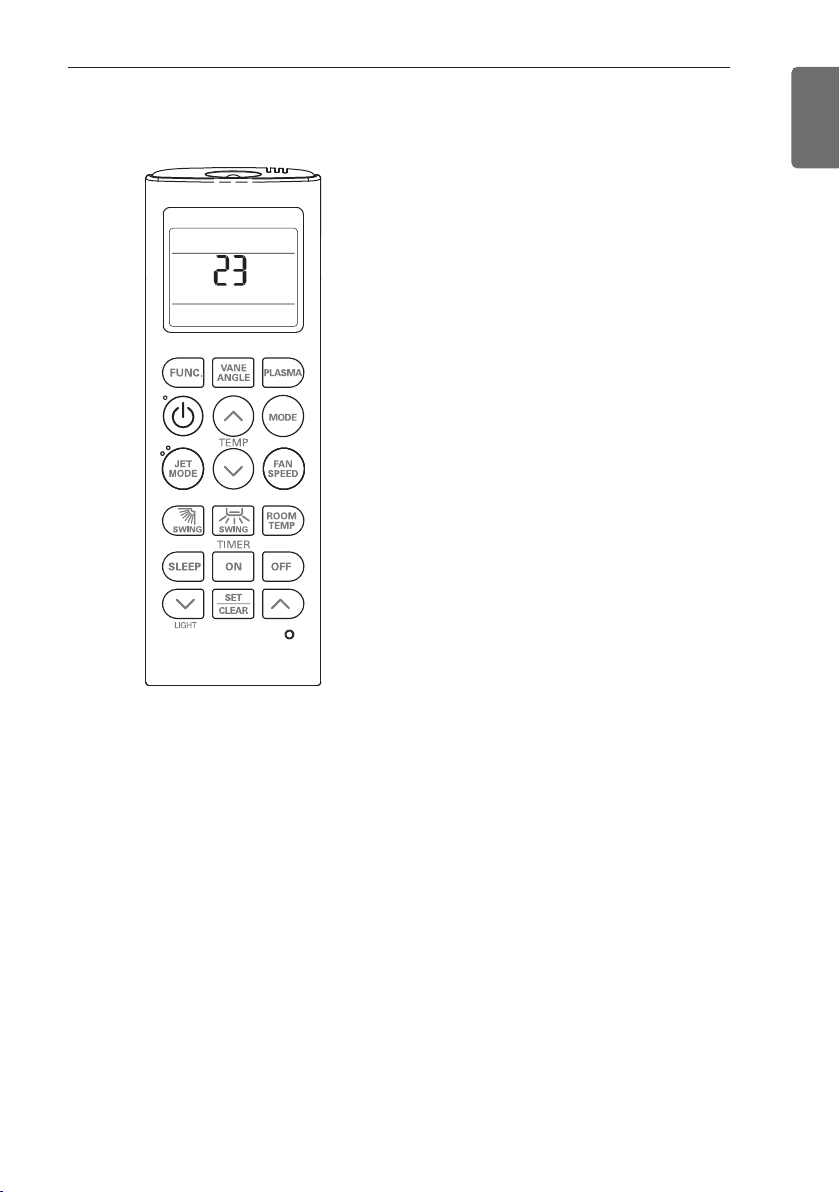
INSTALLATION INSTRUCTIONS
Installer Setting - Setting Address of Central Control
1 With the MODE button pressed, press the
RESET button.
2 By using the temperature setting button, set
the indoor unit address.
• Setting range : 00 ~ FF
3 After setting the address, press the ON/OFF
button toward the indoor unit 1 time.
4 The indoor unit will display the set address to
complete the address setting.
• The address display time and method can
differ by the indoor unit type.
5 Reset the remote controller to use the
general operation mode.
°C/°F (5 s)
TIME (3 s)
63
ENGLISH
Installer Setting - Checking Address of Central Control
1 With the FUNC. button pressed, press the RESET button.
2 Press the ON/OFF button toward the indoor unit 1 time, and the indoor unit will display the set
address in the display window.
• The address display time and method can differ by the indoor unit type.
3 Reset the remote controller to use the general operation mode.

INSTALLATION INSTRUCTIONS
64
ENGLISH
Ceiling Concealed Duct – Low static
Table 1
Chassis
Capacity
(kBtu/h)
L5 9
L5 12
L6 18
L3 24
L5 12 High
L3 18 High
Grade Step CMM
Standard
Compact
Standard
Compact
Standard
Compact
Standard
Compact
LOW
MID
HIGH
LOW
MID
HIGH
LOW
MID
HIGH
LOW
MID
HIGH
LOW
MID
HIGH
LOW
MID
HIGH
Static Pressure [mmAq(Pa)]
0(0) 1(10) 2(20) 3(29) 4(39) 5(49)
Setting Value
32:01 32:02 32:03 32:04 32:05 32:06
8 76 87 96 106 116 116
9.5 87 96 106 114 120 120
11.5 101 109 118 125 130 130
8 76 87 96 106 116 116
9.5 87 96 106 114 120 120
11.5 101 109 118 125 130 130
10 82 87 90 96 106 116
12.5 92 98 105 109 119 128
15 100 106 112 122 129 137
12 89 95 102 106 120 130
16 102 108 115 125 131 139
20 125 131 136 141 142 147
8 76 87 96 106 116 116
9.5 87 96 106 114 120 120
11.5 101 109 118 125 130 130
10 80 90 95 100 110 120
14 97 103 109 117 126 134
18 115 122 127 133 138 142
NOTE
1. The above table shows the correlation between the air rates and E.S.P.
2. Be sure to set the value referring table 1. Unexpected set value will cause mal-function.
3. Table 1 is based at 230 V. According to the fluctuation of voltage, air flow rate varies.

Ceiling Concealed Duct – Mid static
Table 2
Capacity
Chassis
(kBtu/h)
M1 18
M1 24
M1 12 High
M1 18 High
Chassis
M1 30
M2 24 High
M2 30 High
Compact
Compact
Capacity
(kBtu/h)
Compact
Grade Step
Standard
Standard
Grade Step
Standard
LOW
MID
HIGH
LOW
MID
HIGH
LOW
MID
HIGH
LOW
MID
HIGH
LOW 18 96 102 107 110 114 118 122 125 127 130 132
MID 20 102 110 114 118 121 125 127 130 133 134 136
HIGH 22 110 117 121 124 127 130 133 136 137 138 140
LOW 21 84 88 89 90 95 96 100 105 110 112 113
MID 24 88 92 94 95 100 101 108 113 118 118 118
HIGH 28 92 96 99 101 105 108 115 118 124 124 124
LOW 21 84 88 89 90 95 96 100 105 110 112 113
MID 24 88 92 94 95 100 101 108 113 118 118 118
HIGH 28 92 96 99 101 105 108 115 118 124 124 124
2(20) 2.5(25) 3(29) 4(39) 6(59) 8(78)
CMM
32:01 32:02 32:03 32:04 32:05 32:06 32:07 32:08 32:09 32:10 32:11
13 73 74 77 88 93 103 111 117 120 125 128
14.5 76 77 86 91 97 107 114 121 125 128 131
16.5 86 87 90 94 103 110 118 125 128 131 134
14.5 76 77 86 89 97 106 114 121 124 127 130
16.5 86 87 90 94 103 111 118 125 128 131 134
18 90 92 95 99 108 115 122 129 132 135 138
9 64 67 70 72 81 94 103 110 113 117 121
12 68 72 74 76 86 100 108 115 118 121 125
16 81 86 89 93 98 110 118 124 127 131 135
14 76 77 86 89 97 107 114 121 124 127 130
16 86 87 90 94 103 111 118 125 128 131 134
17.5 90 92 95 99 108 115 122 129 132 135 138
2.5(25) 4(39) 5(49) 6(59) 7(69) 8(78) 9(88) 10(98)
CMM
32:01 32:02 32:03 32:04 32:05 32:06 32:07 32:08 32:09 32:10 32:11
INSTALLATION INSTRUCTIONS
Static Pressure [mmAq(Pa)]
10(98) 12(118) 13(127) 14(137) 15(147)
Setting Value
Static Pressure [mmAq(Pa)]
Setting Value
65
11(108) 13(127) 15(147)
ENGLISH

66
ENGLISH
INSTALLATION INSTRUCTIONS
Capacity
Chassis
M2 36
M3 48
M3 48 High
M3 36 High
M3 42 High
M3 60
Grade Step CMM
(kBtu/h)
Standard
Compact
Standard
Compact
Standard
Compact
LOW
MID
HIGH
LOW
MID
HIGH
LOW
MID
HIGH
LOW
MID
HIGH
LOW
MID
HIGH
LOW
MID
HIGH
Static Pressure [mmAq(Pa)]
4(39) 5(49) 6(59) 7(69) 8(78) 9(88) 10(98)
Setting Value
32:01 32:02 32:03 32:04 32:05 32:06 32:07 32:08 32:09 32:10 32:11
24 88 91 95 100 101 108 113 115 118 118 118
28 93 97 101 105 108 115 118 120 124 124 124
32 101 105 109 112 115 119 123 126 128 128 128
28 74 76 79 82 89 92 94 96 99 102 107
34 78 82 84 89 94 96 98 101 104 106 112
40 83 89 92 94 98 100 102 105 108 110 116
28 74 76 79 82 89 92 94 96 99 102 107
34 78 82 84 89 94 96 98 101 104 106 112
40 83 89 92 94 98 100 102 105 108 110 116
28 74 76 79 82 89 92 94 96 99 102 107
34 78 82 84 89 94 96 98 101 104 106 112
40 83 89 92 94 98 100 102 105 108 110 116
28 74 76 79 82 89 92 94 96 99 102 107
34 78 82 84 89 94 96 98 101 104 106 112
40 83 89 92 94 98 100 102 105 108 110 116
40 82 89 92 94 98 100 102 105 108 110 113
45 90 92 96 98 102 104 106 109 112 114 117
50 94 97 100 104 107 109 112 115 117 119 121
11(108) 12(118) 13(127) 15(147)
Chassis
M2 42
Capacity
Grade Step CMM
(kBtu/h)
Standard
Compact
Static Pressure [mmAq(Pa)]
5(49) 6(59) 7(69) 8(78) 9(88) 10(98)
Setting Value
32:01 32:02 32:03 32:04 32:05 32:06 32:07 32:08 32:09 32:10 32:11
LOW
28 100 103 106 110 114 118 121 125 128 133 136
MID
33 108 111 114 118 122 125 128 131 134 138 140
HIGH
38 117 120 124 127 130 133 135 138 140 144 147
11(108) 12(118) 13(127) 14(137) 15(147)

INSTALLATION INSTRUCTIONS
NOTE
1. Be sure to set the value referring table 2. Unexpected set value will cause mal-function.
2. Table 2 is based at 230 V. According to the fluctuation of voltage, air flow rate varies.
3. Factory Set(External Static Pressure) each Model
67
ENGLISH
Capacity
(kBtu/h)
18
24
30
36
42
48
60
* If it is zero static pressure, please set value below Maximum value.
Chassis Maximum value
M1 115
M2 120
M3 98
Factory set (E.S.P.) mmAq(Pa)
6(59)

DIP SWITCH SETTING
Indoor PCB
68
ENGLISH
DIP SWITCH SETTING
Function Description Setting Off Setting On Default
SW3 Group Control
SW4
SW5 Installation
Dry Contact
Mode
Selection of Master
Selection of Dry
Contact Mode
Fan continuous
or Slave
operation
Indoor PCB
Indoor PCB
Master Slave Off
Wired/Wireless remote
Selection of Manual or Auto
controller
operation Mode
Continuous operation
Removal
Auto Off
Working Off

 Loading...