

LG URNU76GB8A2 INSTALLATION INSTRUCTIONS
LG


 System
Indoor Unit (2 Series)
INSTALLATION MANUAL
Type: Ceiling Concealed Duct - High Static
IMPORTANT
•Please read this installation manual completely before installing the product.
•Installation work must be performed in accordance with the national wiring standards by authorized personnel only.
•Please retain this installation manual for future reference after reading it thoroughly.
<![endif]>DEUTSCH FRANÇAIS ESPAÑOL ITALIANO ENGLISH


 Ceiling Concealed Duct - High Static Type Indoor Unit Installation Manual
TABLE OF CONTENTS
Installation Requirements
Features ................................... |
3 |
Safety Precautions ................. |
4 |
Installation |
|
Selection the best location .... |
7 |
Ceiling opening dimension |
|
and hanging bolt location ...... |
8 |
Indoor Unit Installation........... |
9 |
Wiring Connection ................. |
9 |
Checking the Drainage........ |
10 |
Installation of Remote con- |
|
troller..................................... |
13 |
Optional Operation of Wired |
|
Remote Controller ............... |
15 |
Required Parts |
|
Required Tools |
|
|
|
Four type "A" screws
Connecting cable
Pipes: Gas side Liquid side
(Refer to Product Data)
Insulation materials
Additional drain pipe
Level gauge
Screw driver
Electric drill
Hole core drill
Flaring tool set
Specified torque wrenches (different depending on model No.)
Spanner .......Half union
A glass of water
Screw driver
Hexagonal wrench
Gas-leak detector
Vacuum pump
Gauge manifold
Owner's manual
Thermometer
How to Set E.S.P? |
................16 |
2 


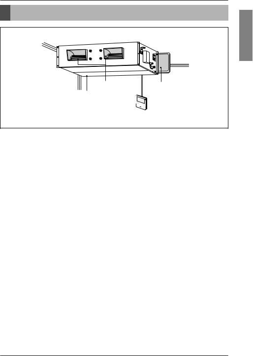
 Indoor Unit
Feature
Features
<![if ! IE]><![endif]>ENGLISH
Air outlet vents |
Air filters |
Air intake vents
Wired Remote Controller 


Installation Manual 3
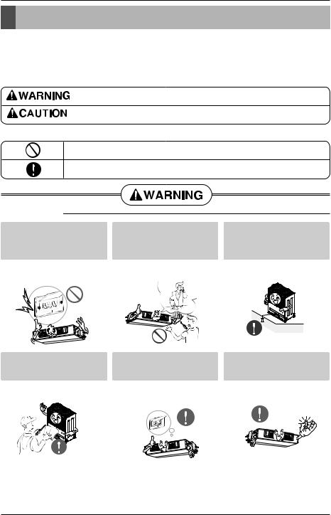
Safety Precautions
Safety Precautions
To prevent injury to the user or other people and property damage, the following instructions must be followed.
■Be sure to read before installing the air conditioner.
■Be sure to observe the cautions specified here as they include important items related to safety.
■Incorrect operation due to ignoring instruction will cause harm or damage. The seriousness is classified by the following indications.
This symbol indicates the possibility of death or serious injury.
This symbol indicates the possibility of injury or damage to properties only.
■ Meanings of symbols used in this manual are as shown below.
Be sure not to do.
Be sure to follow the instruction.
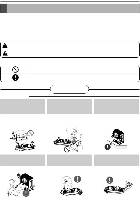
■ Installation
Do not use a defective or underrated circuit breaker. Use this appliance on a dedicated circuit.
• There is risk of fire or electric shock.
Install the panel and the cover of control box securely.
For electrical work, contact the dealer, seller, a qualified electrician, or an Authorized Service Center.
•Do not disassemble or repair the product. There is risk of fire or elec-
tric shock.
Always install a dedicated circuit and breaker.
• There is risk of fire or electric shock. |
• Improper wiring or installation may |
|
cause fire or electric shock. |
Always ground the product.
• There is risk of fire or electric shock.
Use the correctly rated breaker or fuse.
• There is risk of fire or electric shock.
4 


 Indoor Unit
|
|
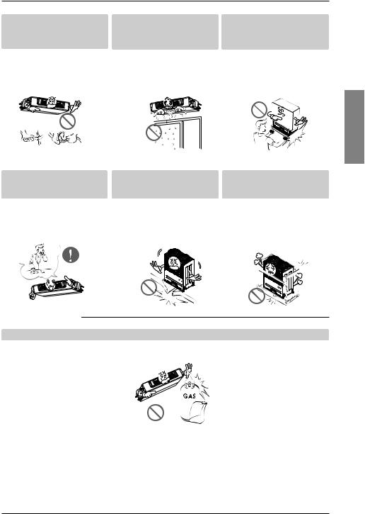
Safety Precautions |
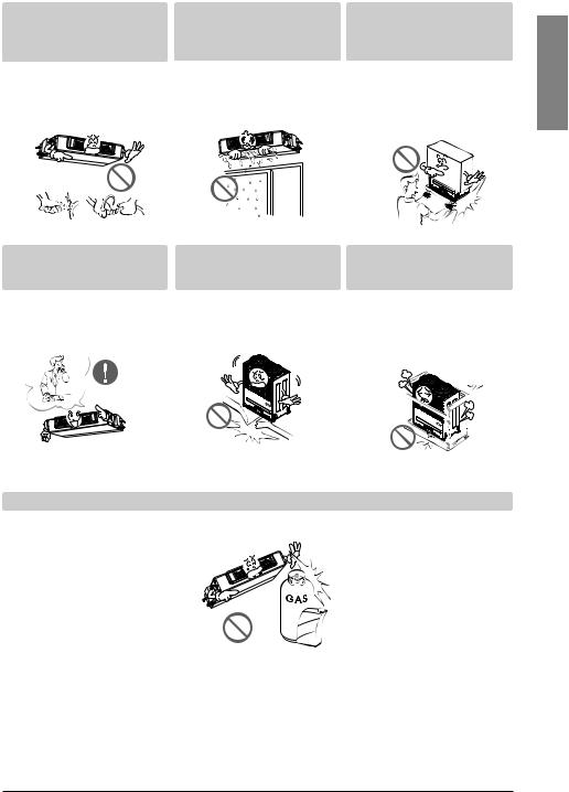
Do not modify or extend the |
Do not let the air conditioner |
Be cautious when unpacking |
power cable. |
run for a long time when the |
and installing the product. |
|
humidity is very high and a door |
|
|
or a window is left open. |
|
• There is risk of fire or electric shock. |
• Moisture may condense and wet or |
• Sharp edges could cause injury. Be |
|
damage furniture. |
especially careful of the case edges |
|
|
and the fins on the condenser and |
|
|
evaporator. |
For installation, always contact |
Do not install the product on a |
Be sure the installation area |
|
the dealer or an Authorized |
defective installation stand. |
does not deteriorate with age. |
|
Service Center. |
|
|
|
• There is risk of fire, electric shock, |
• It may cause injury, accident, or |
• If the base collapses, the air condi- |
|
explosion, or injury. |
damage to the product. |
tioner could fall with it, causing prop- |
|
|
|
|
erty damage, product failure, and |
|
|
|
personal injury. |
|
|
|
|
|
|
|
|
|
|
|
|
<![endif]>ENGLISH
Do not store or use flammable gas or combustibles near the product.
• There is risk of fire or failure of product.
Gasolin
Installation Manual 5
Safety Precautions
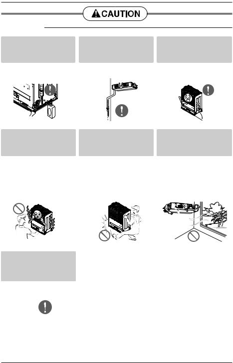
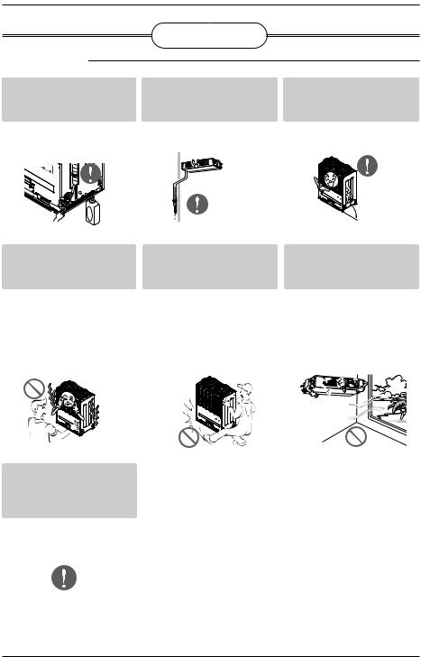
■ Installation
If you eat the liquid from the batteries, brush your teeth and see doctor. Do not use the remote if the batteries have leaked.
•The chemicals in batteries could cause burns or other health hazards.
Keep level even when installing
-the product.
• To avoid vibration or water leakage.
90˚
Do not install the product where it will be exposed to sea wind (salt spray) directly.
•It may cause corrosion on the product. Corrosion, particularly on the condenser and evaporator fins, could cause product malfunction or inefficient operation.
6 


 Indoor Unit
Installation
Installation
Read completely, then follow step by step.
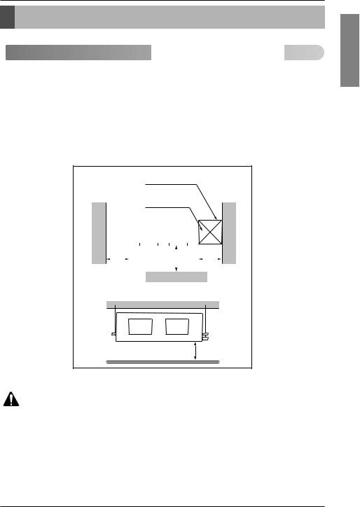
 Selection of the best location


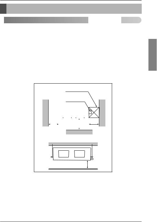
Install the air conditioner in the location that satisfies the following conditions.
•The place shall easily bear a load exceeding four times the indoor unit’s weight.
•The place shall be able to inspect the unit as the figure.
•The place where the unit shall be leveled.
•The place shall allow easy water drainage.(Suitable dimension “H” is necessary to get a slope to drain as figure.)
•The place shall easily connect with the outdoor unit.
•The place where the unit is not affected by an electrical noise.
•The place where air circulation in the room will be good .
•There should not be any heat source or steam near the unit.
Top view |
Inspection hole |
(unit: mm) |
(600X600) |
|
Control box |
|
|
|
|
|
|
|
|
|
|
|
|
|
|
|
|
|
|
|
|
|
|
|
|
|
|
|
|
|
|
|
|
|
|
|
|
|
|
|
|
|
|
|
|
|
|
|
|
600 |
|
|
|
<![if ! IE]> <![endif]>1000 |
|
|
600 |
||||
|
|
|
|
|
|||||||
|
|
|
|
|
|
|
|
||||
|
|
|
|
|
|
|
|
|
|
|
|
|
|
|
|
|
|
|
|
|
|
|
|
Front
Front view
H
CAUTION : In case that the unit is installed near the sea, the installation parts may be corroded by salt, The installation parts (and the unit) should be taken appropriate anti-corrosion measures.
<![endif]>ENGLISH
Installation Manual 7
Installation
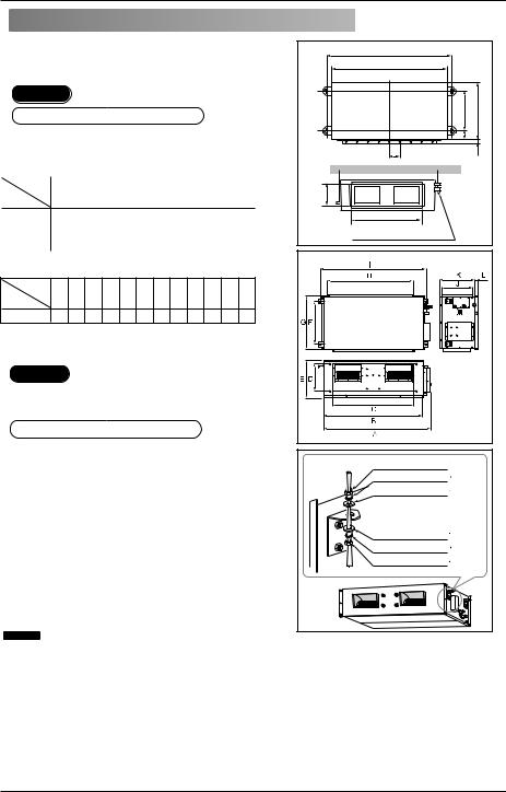
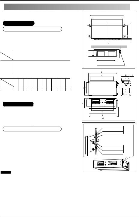
 Ceiling dimension and hanging bolt location


■Installation of Unit
Install the unit above the ceiling correctly.
CASE 1
POSITION OF SUSPENSION BOLT
-canvas between the unit and duct to vibration.
(Unit:mm)
Dimension |
|
|
|
|
|
|
|
|
|
|
A |
B |
C |
D |
E |
F |
(G) |
H |
I |
Capacity(Btu/h) |
|
|
|
|
|
|
|
|
|
7/9/12/15/18/24k |
932 |
882 |
355 |
47 |
450 |
30 |
87 |
750 |
158 |
|
|
|
|
|
|
|
|
|
|
28/36/42k |
1232 |
1182 |
355 |
47 |
450 |
30 |
87 |
830 |
186 |
|
|
|
|
|
|
|
|
|
|
48k |
1282 |
1230 |
477 |
56 |
590 |
30 |
120 |
1006 |
294 |
|
|
|
|
|
|
|
|
|
|
(Unit:mm)
Dimension
A B C D E F G H I J K L
Capacity(Btu/h)
76/96k 1680 1565 1160 330 460 580 700 1400 1635 390 445 15
CASE 2
leaning to a drainage hole side as a figwater drainage.
POSITION OF CONSOLE BOLT
the unit will be leveled and that can weight of the unit.
the unit can withstand its vibration. service can be easily performed.
NOTICE
BH/BG/BR Chassis |
A |
|
|
|
|
|
B |
|
|
<![if ! IE]> <![endif]>C |
<![if ! IE]> <![endif]>E |
|
<![if ! IE]> <![endif]>D |
|
|
(G) |
<![if ! IE]> <![endif]>F |
| <![if ! IE]> <![endif]>I |
|
|
|
H |
|
Drainage hole |
|
|
B8 Chassis |
M10 Nut |
X 4 |
(Local |
|
M10 SP. washer X 4 |
|||
supply) |
|||
M10 washer |
X 4 |
|
|
M10 washer |
X 4 |
(Local |
|
M10 SP. washer X 4 |
|||
supply) |
|||
M10 Nut |
X 4 |
|
|
• Throughly study the following installation locations:
1.In such places as restaurants and kitchens, considerable amount of oil steam and flour adhere to the fan, the fin of the heat exchanger, resulting in heat exchange reduction, spraying, dispersing of water drops, etc.
In these cases, take the following actions:
•Make sure that the ventilation fan for smoke-collecting hood on a cooking table has sufficient capacity so that it draws oily steam which should not flow into the suction of the air conditioner.
•Make enough distance from a cooking room to install the air conditioner in such a place where it may not suck in oil steam.
2.Avoid installing air conditioner in such circumstances where cutting oil mist or iron powder is in suspension in factories, etc.
3.Avoid places where inflammable gas is generated, flows in, is stored or vented.
4.Avoid places where sulfurous acid gas or corrosive gas is generated.
5.Avoid places near high frequency generators.
8 


 Indoor Unit
Installation
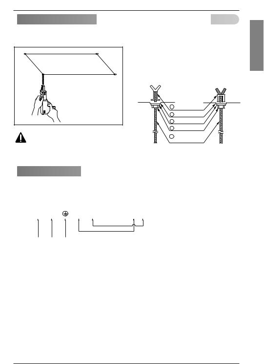
 Indoor Unit Installation


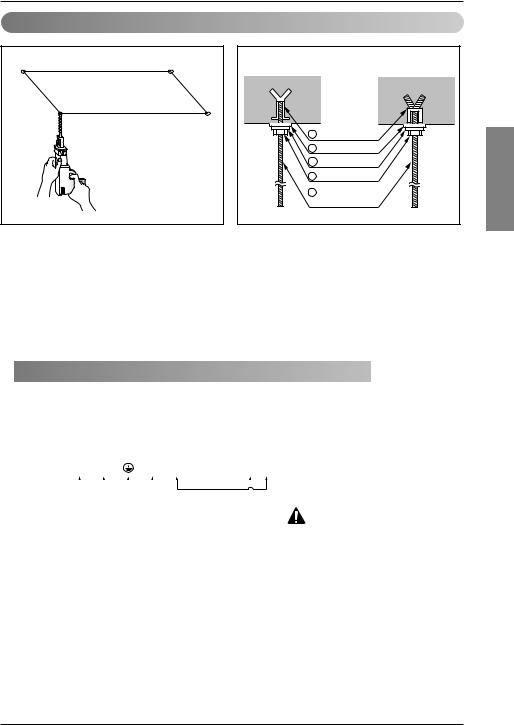
•Select and mark the position for fixing bolts.
•Drill the hole for set anchor on the face of ceiling.
CAUTION : Tighten the nut and bolt to prevent unit falling.
•Insert the set anchor and washer onto the suspension bolts for locking the suspension bolts on the ceiling.
•Mount the suspension bolts to the set anchor firmly.
•Secure the installation plates onto the suspension bolts (adjust level roughly) using nuts, washers and spring washers.
Old building |
|
New building |
|
|
|
1 Set anchor
2 Plate washer
3 Spring washer
4Nut
5Suspension bolts
 Wiring Connection


Connect the wires to the terminals on the control board individually according to the outdoor unit connection.
• Ensure that the color of the wires of outdoor unit and the terminal No. are the same as those of indoor unit respectively.
|
Terminal Block Indoor |
|
|
Outdoor unit |
Indoor unit |
Central controller |
Outdoor unit |
||||||||
1(L) |
2(N) |
|
3 |
4 |
|
SODU |
SODU |
IDU |
IDU |
INTERNET |
DRY1 |
DRY2 |
GND |
12V |
|
|
|
|
|
|
|
|
|
|
|
|
|
|
|
|
|
INDOOR POWER INPUT
 WARNING : Make sure that the screws of the terminal are free from looseness.
Clamping of cables
1)Arrange 2 power cables on the control panel.
2)First, fasten the steel clamp with a screw to the inner boss of control panel.
3)For the cooling model, fix the other side of the clamp with a screw strongly. For the heat pump model, put the 0.75mm2 cable(thinner cable) on the clamp and tighten it with a plastic clamp to the other boss of the control panel.
<![endif]>ENGLISH
Installation Manual 9
Installation
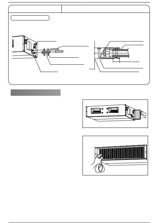
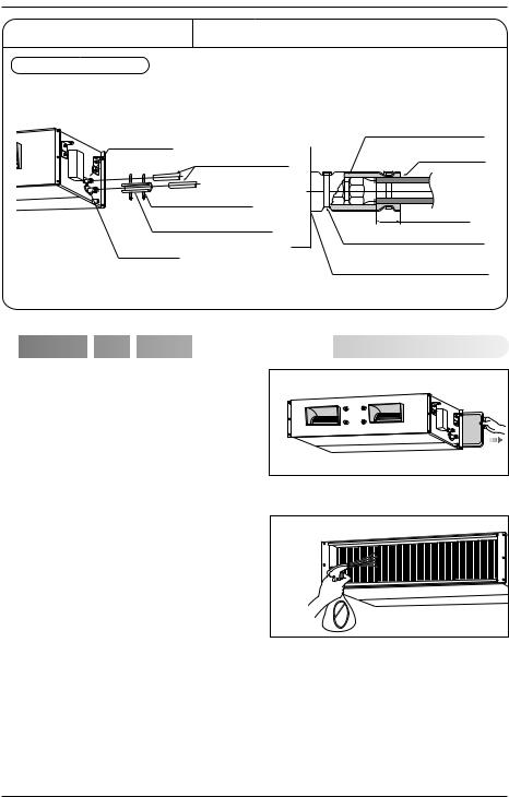
INSULATION, OTHERS
Insulate the joint and tubes completely.
THERMAL INSULATION All thermal insulation must comply with local requirement.
INDOOR UNIT
Union for liquid pipe
Refrigerant pipe and thermal

 insulator(Local supply)
Hose crip for thermal insulator (Local supply)
Thermal insulator for refrigerant pipe (Local supply)
Union for gas pipe
Thermal insulator for refrigerant pipe (Local supply)
Overlap with thermal
insulator for piping.
Hose crip for thermal insulator(Local supply)
Make sure that there is no clearance here.
 Checking the Drainage


1. Remove the Air Filter.
2. Check the drainage.
•Spray one or two glasses of water upon the evaporator.
• Ensure that water flows drain hose of indoor unit without any leakage.
10 


 Indoor Unit
Installation
CAUTION
1. Install declination of the indoor unit is very important for the drain of the duct type air conditioner. |
<![if ! IE]> <![endif]>ENGLISH |
|
|
2. Minimum thickness of the insulation for the connecting pipe shall be 5mm. |
|
Front of view
•The unit must be horizontal or declined to the drain hose connected when finished installation.
|
|
Ceiling |
|
|
|
<![if ! IE]> <![endif]>1~3mm |
|
Drain Pump |
Drainage hole |
Drain Pump |
Drainage hole |
unuse |
use |
CAUTION FOR GRADIENT OF UNIT AND DRAIN PIPING
Lay the drain hose with a downware inclination so water will drain out.
• Alway lay the drain with downward inclination |
Thermal insulator |
|
(Local supply) |
||
(1/50 to 1/100). |
||
Drainage pipe |
||
Prevent any upward flow or reverse flow in any |
||
(Local supply) |
||
part. |
||
Unit |
||
• 5mm or thicker formed thermal insulator shall |
|
|
always be provided for the drain pipe. |
|
Make sure to be closed. |
Drainage hole |
• Upward routing not allowed
CORRECT
•Install the P-Trap (or U-Trap) to prevent a water leakage caused by the blocking of intake air filter.
INCORRECT
Applied U-Trap Dimension
A ≥ |
70mm |
|
||
B ≥ |
2C |
|
|
|
C ≥ |
2 x SP |
B |
||
SP = External Pressure |
||||
|
(mmAq) |
C |
||
Ex) External Pressure |
U-Trap |
|||
|
= 10mmAq |
|||
|
A |
≥ |
70mm |
A |
|
B |
≥ |
40mm |
|
|
C |
≥ |
20mm |
|
Installation Manual 11

Installation
CAUTION:
After the confirmation of the above conditions, prepare the wiring as follows:
1)Never fail to have an individual power specialized for the air conditioner. As for the method of wiring, be guided by the circuit diagram posted on the inside of control box cover.
2)Provide a circuit breaker switch between power source and the unit.
3)The screws which fasten the wiring in the casing of electrical fittings are liable to come loose from vibrations to which the unit is subjected during the course of transportation. Check them and make sure that they are all tightly fastened. (If they are loose, it could give rise to burn-out of the wires.)
4)Specification of power source
5)Confirm that electrical capacity is sufficient.
6)Be sure that the starting voltage is maintained at more than 90 percent of the rated voltage marked on the name plate.
7)Confirm that the cable thickness is as specified in the power sources specification. (Particularly note the relation between cable length and thickness.)
8)Never fail to equip a leakage breaker where it is wet or moist.
9)The following troubles would be caused by voltage drop-down.
•Vibration of a magnetic switch, damage on the contact point, fuse breaking, disturbance by the normal function of an overload protection device.
•Proper starting power is not given to the compressor.
HAND OVER
Teach the customer the operation and maintenance procedures, using the operation manual. (air filter cleaning, temperature control, etc.)
12 


 Indoor Unit
Installation

 Installation
 of
of Wired
Wired Remote
 Controller


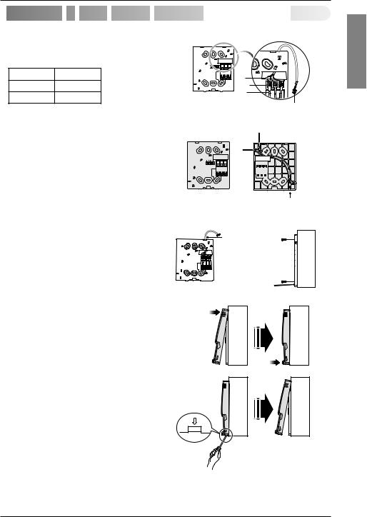
1.Connect the wired remote controller cable to the wired remote controller installation board as shown in the right picture.
|
|
12V SIG GND |
12V |
Red wire |
Red |
|
|
|
SIG |
Yellow wire |
Yellow |
GND |
Black wire |
Black |
|
The wired remote controller cable is connected as factory default.
2. After fixing the cable to the guide slot, attach the wired remote controller installation board at the desired location.
Remote Controller
Cable
•Before fixing the wired remote controller cable to the guide slot, remove any clogged part of the case in the direction to install before the installation.
3.After locating the wired remote controller installation board at the desired location, screw the unit firmly. (When there is a buried box, install the wired remote controller board to fit the buried box.)
 Guide slot
<Front side of |
|
<Rear side of |
|
installation board> |
installation board> |
||
Top |
Fixate the remote |
|
|
|
|
||
|
controller cable |
|
|
|
to the guide slot. |
Wall |
|
|
|
Use the screws |
|
|
|
Side |
|
|
|
for fixate the unit |
|
|
|
firmly on the wall. |
|
Bottom |
|
Installation board |
|
|
|
|
|
• Use the screw provided.
4.After fixing the top part of the wired remote controller to the installation board as shown in beside picture, press the bottom part to assemble the controller to it’s board.
When disassemble the wired remote controller from the installation board, use the driver as shown in the right picture and insert it into the hole with the arrow. And when you pull the driver in the front direction, the wired remote controller will be separated.
Wall |
Wall |
Side |
Side |
Wall |
Wall |
Side |
Side |
<![endif]>ENGLISH
Installation Manual 13
Installation
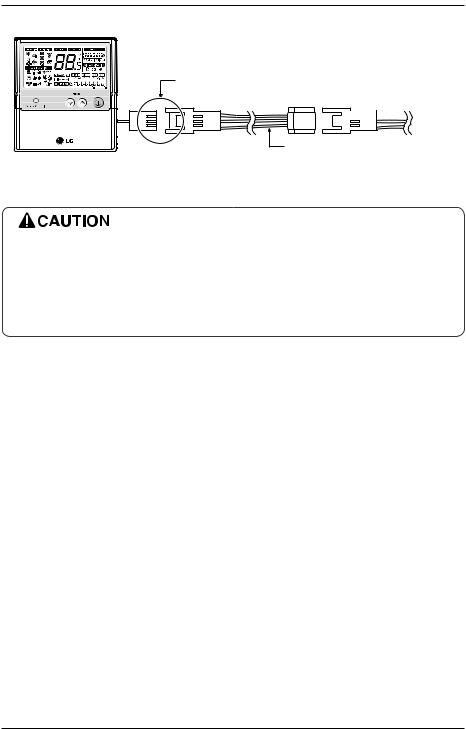
5. Use the connecting cable to connect the indoor unit and the wired remote controller.
Check whether the connector is connected correctly.

 Indoor
unit side
Connecting cable
6.When the distance between the wired remote controller and the indoor unit is 10m and above, use the extension cable.
When installing the wired remote controller, do not bury it in the wall. (It can cause damage in the temperature sensor.)
Do not install the cable to be 50m or above. (It can cause communication error.)
•When installing the extension cable, check the connecting direction of the connector of the remote controller side and the product side for correct installation.
•If you install the extension cable in the opposite direction, the connector will not be connected.
•Specification of extension cable: 2547 1007 22# 2 core 3 shield 5 or above.
14 


 Indoor Unit
Optional Operation of Wired Remote Controller

 Optional
 Operation of
 Wired
Wired Remote Controller


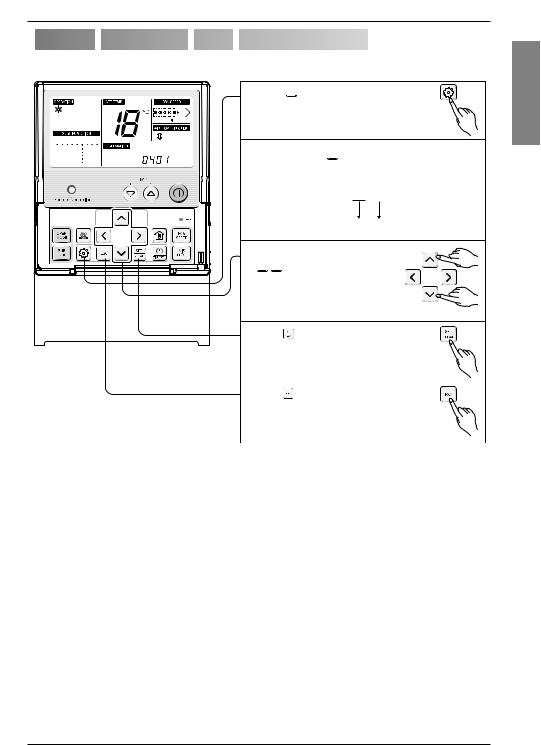
Two Thermistor System
1. Press 

 button for 4 seconds to enter the installer setting mode until timer segment display “01:01”.
2. Repeat pressing  button to select Function code 04.
04:01
Function Code Thermistor setting
3. Set Thermistor mode by pressing


 button
(01: Remote Controller, 02: Indoor, 03: 2TH)
|
|
|
4. Press |
|
button to save or release |
|
|
|
|
|
|
|
|
|
|||
|
|
|
|
|
|
|
|
|
|
|
|
5. Press |
|
button to exit or system |
|||
|
|
|
will automatically exit after 25 seconds |
|||||
|
|
|
without any input. |
|||||
|
|
|
|
|
|
|
|
|
Therefore system will use value that sensed from indoor unit or remote controller |
||||||||
|
|
|
|
|
||||
Temperature sensor location |
|
Function |
|
|
|
|||
|
|
|
|
|||||
01 |
Remote controller |
Operation in remote controller Temperature sensor |
|
|||||
02 |
Indoor unit |
Operation in indoor unit temperature sensor |
|
|||||
03 |
2-Thermistor |
Operation in lower temperature after comparing the temperature |
|
|||||
between the indoor unit and remote controller |
|
|
|
|||||
|
|
|
||||||
|
|
|
|
|||||
If you want to know more Optional Operation, please refer to Wired Remote Controller Manual. |
||||||||
<![endif]>ENGLISH
Installation Manual 15

How to Set E.S.P?
How to Set E.S.P?
What is an E.S.P function?
This is the function that decides the strength of the wind for each wind level and because this function is to make the installation easier, please do not use this function when using the remote controller.
If you set ESP incorrectly, the air conditioner may malfunction.
This setting must be carried out by a certificated-technician.
This function is using for only Duct product
1. Press 
 button for 4 seconds to enter the installer setting mode until timer segment display "01:01".
2. Repeat pressing Function Setting key to select Function code 03.
03:00:155
Function Code ESP step ESP value
3. Set ESP step by pressing 


 button (01: very low,
02: low, 03: medium, 04: high. 05: power).
4. Move to ESP setting by pressing 
 button.
5. Press 


 button to select ESP value(0~255).
6. Press  button to save or release
7. Press 
 button to exit or the system will automatically exit after 25 seconds without any input
Weak and Power setting is not available for some products.
Because the ESP value is already appropriately set when manufactured from the factory, it is recommended that you do not change the ESP value.
16 


 Indoor Unit

How to Set E.S.P?
ARNU07GBHA2, ARNU09GBHA2, ARNU12GBHA2 |
|
|
|
|
|
|
|
|
|
|||||||||||||||||||
ARNU15GBHA2, ARNU18GBHA2, ARNU24GBHA2 |
|
|
|
|
|
(Unit: CMM) |
||||||||||||||||||||||
|
|
|
|
|
|
|
|
|
|
|
|
|
|
|
|
|
|
|
|
|
|
|
|
|||||
Setting Value |
|
|
|
|
|
|
|
|
Static Pressure(mmAq(Pa)) |
|
|
|
|
|
|
|
|
|
|
|
|
|||||||
|
|
|
|
|
|
|
|
|
|
|
|
|
|
|
|
|
|
|
|
|
|
|
|
|
|
|
|
|
|
3(30) |
|
4(40) |
|
5(50) |
|
6(60) |
|
7(70) |
|
8(80) |
|
|
9(90) |
|
|
10(100) |
|
12(120) |
|||||||||
|
|
|
|
|
|
|
|
|
|
|
|
|
|
|
|
|
|
|
|
|
|
|
|
|||||
70 |
4.1 |
|
- |
|
|
|
- |
|
- |
|
- |
|
- |
|
|
- |
|
|
|
|
- |
|
- |
|||||
80 |
7.6 |
|
- |
|
|
|
- |
|
- |
|
- |
|
- |
|
|
- |
|
|
|
|
- |
|
- |
|||||
|
|
|
|
|
|
|
|
|
|
|
|
|
|
|
|
|
|
|
|
|
|
|
|
|||||
90 |
10.7 |
|
8.1 |
|
|
|
6.3 |
|
4.9 |
|
- |
|
- |
|
|
- |
|
|
|
|
- |
|
- |
|||||
|
|
|
|
|
|
|
|
|
|
|
|
|
|
|
|
|
|
|
|
|
|
|
||||||
100 |
13.4 |
|
11.2 |
|
|
9.6 |
|
7.5 |
|
4.0 |
|
- |
|
|
- |
|
|
|
|
- |
|
- |
||||||
|
|
|
|
|
|
|
|
|
|
|
|
|
|
|
|
|
|
|
|
|
|
|
||||||
110 |
15.9 |
|
13.2 |
|
|
12.6 |
|
10.3 |
|
7.7 |
|
5.5 |
|
|
- |
|
|
|
|
- |
|
- |
||||||
|
|
|
|
|
|
|
|
|
|
|
|
|
|
|
|
|
|
|
|
|
|
|||||||
120 |
18.6 |
|
16.2 |
|
|
15.2 |
|
12.8 |
|
11.1 |
|
9.1 |
|
|
6.7 |
|
|
|
5.3 |
|
- |
|||||||
|
|
|
|
|
|
|
|
|
|
|
|
|
|
|
|
|
|
|
|
|
|
|||||||
130 |
19.8 |
|
18.8 |
|
|
18.0 |
|
15.3 |
|
14.2 |
|
12.4 |
|
|
10.4 |
|
|
|
8.8 |
|
5.7 |
|||||||
140 |
22.3 |
|
21.1 |
|
|
20.3 |
|
17.7 |
|
17.1 |
|
15.5 |
|
|
13.7 |
|
|
12.6 |
|
9.7 |
||||||||
145 |
23.2 |
|
22.2 |
|
|
21.4 |
|
19.1 |
|
18.4 |
|
16.9 |
|
|
15.3 |
|
|
13.8 |
|
11.8 |
||||||||
150 |
24.3 |
|
23.1 |
|
|
22.3 |
|
21.1 |
|
19.8 |
|
18.3 |
|
|
16.8 |
|
|
15.2 |
|
13.0 |
||||||||
|
|
|
|
|
|
|
|
|
|
|
|
|
|
|
|
|
||||||||||||
ARNU28GBGA2, ARNU36GBGA2, ARNU42GBGA2 |
|
|
|
|
|
(Unit: CMM) |
||||||||||||||||||||||
|
|
|
|
|
|
|
|
|
|
|
|
|
|
|
|
|
|
|
|
|
|
|
|
|
||||
|
|
|
|
|
|
|
|
|
|
|
|
|
|
|
|
|
|
|
|
|
|
|
|
|
|
|
|
|
Setting Value |
|
|
|
|
|
|
|
|
Static Pressure(mmAq(Pa)) |
|
|
|
|
|
|
|
|
|
|
|
|
|||||||
|
|
|
|
|
|
|
|
|
|
|
|
|
|
|
|
|
|
|
|
|
|
|
|
|
|
|
|
|
|
5(50) |
|
6(60) |
|
7(70) |
|
8(80) |
|
9(90) |
10(100) |
|
12(120) |
|
14(140) |
|
16(160) |
||||||||||||
|
|
|
|
|
|
|
|
|
|
|
|
|
|
|
|
|
|
|
|
|
|
|
|
|
|
|
|
|
70 |
- |
|
- |
|
|
|
- |
|
- |
|
- |
- |
|
|
- |
|
|
|
|
- |
|
- |
||||||
80 |
4.0 |
|
- |
|
|
|
- |
|
- |
|
- |
- |
|
|
- |
|
|
|
|
- |
|
- |
||||||
90 |
12.1 |
|
6.9 |
|
|
4.13 |
|
- |
|
- |
- |
|
|
- |
|
|
|
|
- |
|
- |
|||||||
100 |
17.0 |
|
15.5 |
|
11.01 |
|
6.2 |
|
4.2 |
- |
|
|
- |
|
|
|
|
- |
|
- |
||||||||
110 |
21.4 |
|
19.6 |
|
17.53 |
|
14.0 |
|
11.6 |
6.6 |
|
|
- |
|
|
|
|
- |
|
- |
||||||||
120 |
25.8 |
|
24.0 |
|
|
21.8 |
|
19.8 |
|
17.9 |
14.6 |
|
|
12.1 |
|
|
|
- |
|
- |
||||||||
130 |
30.0 |
|
28.5 |
|
26.93 |
|
25.3 |
|
23.4 |
21.8 |
|
|
18.1 |
|
|
14.6 |
|
11.3 |
||||||||||
|
|
|
|
|
|
|
|
|
|
|
|
|
|
|
|
|
|
|
|
|
|
|
|
|
|
|
||
140 |
36.0 |
|
32.1 |
|
30.41 |
|
29.0 |
|
27.4 |
25.9 |
|
|
21.6 |
|
|
17.8 |
|
14.5 |
||||||||||
|
|
|
|
|
|
|
|
|
|
|
|
|
|
|
|
|
|
|
|
|
|
|
|
|
|
|
|
|
143 |
37.5 |
|
33.9 |
|
|
32.1 |
|
30.7 |
|
28.8 |
27.2 |
|
|
23.0 |
|
|
20.1 |
|
16.8 |
|||||||||
|
|
|
|
|
|
|
|
|
|
|
|
|
|
|
|
|
|
|
|
|
|
|
|
|
|
|
|
|
150 |
41.0 |
|
38.0 |
|
|
36.0 |
|
34.5 |
|
32.1 |
30.1 |
|
|
26.3 |
|
|
22.4 |
|
18.2 |
|||||||||
|
|
|
|
|
|
|
|
|
|
|
|
|
|
|
|
|
|
|
|
|
|
|
|
|
|
|
|
|
160 |
42.4 |
|
41.6 |
|
|
38.2 |
|
36.1 |
|
35 |
34.6 |
|
|
31.1 |
|
|
26.8 |
|
23.3 |
|||||||||
|
|
|
|
|
|
|
|
|
|
|
|
|
|
|
|
|
|
|
|
|
|
|
|
|
|
|
|
|
ARNU48GBRA2 |
|
|
|
|
|
|
|
|
|
|
|
|
|
|
|
|
|
|
|
|
|
|
|
(Unit: CMM) |
||||
|
|
|
|
|
|
|
|
|
|
|
|
|
|
|
|
|
|
|
|
|
|
|
|
|
||||
|
|
|
|
|
|
|
|
|
|
|
|
|
|
|
|
|
|
|
|
|
|
|
|
|
|
|
|
|
Setting Value |
|
|
|
|
|
|
|
|
Static Pressure(mmAq(Pa)) |
|
|
|
|
|
|
|
|
|
|
|
|
|||||||
|
|
|
|
|
|
|
|
|
|
|
|
|
|
|
|
|
|
|
|
|
|
|
|
|
|
|
|
|
|
5(50) |
6(60) |
|
8(80) |
|
10(100) |
|
12(120) |
14(140) |
15(150) |
16(160) |
17(170) |
|
18(180) |
|
20(200) |
||||||||||||
|
|
|
|
|
|
|
|
|
|
|
|
|
|
|
|
|
|
|
|
|
|
|
|
|
|
|
|
|
91 |
46.5 |
43.7 |
|
38.2 |
|
31.3 |
|
23.2 |
|
14.0 |
9.0 |
|
3.7 |
|
- |
|
|
|
- |
|
|
- |
||||||
96 |
49.9 |
46.1 |
|
43.0 |
|
33.5 |
|
31.1 |
|
18.4 |
13.7 |
|
9.0 |
|
2.6 |
|
|
- |
|
|
- |
|||||||
101 |
52.1 |
50.2 |
|
47.9 |
|
39.5 |
|
37.4 |
|
27.3 |
25.2 |
|
17.8 |
|
8.9 |
|
|
6.1 |
|
|
- |
|||||||
106 |
51.4 |
51.2 |
|
50.4 |
|
44.4 |
|
43.1 |
|
33.3 |
32.1 |
|
28.9 |
|
21.0 |
|
17.9 |
|
|
8.3 |
||||||||
111 |
53.6 |
53.7 |
|
52.9 |
|
49.9 |
|
48.3 |
|
40.6 |
40.2 |
|
32.8 |
|
31.5 |
|
27.2 |
|
|
17.5 |
||||||||
116 |
62.3 |
61.0 |
|
60.3 |
|
55.7 |
|
50.8 |
|
44.8 |
42.6 |
|
40.1 |
|
37.6 |
|
32.5 |
|
|
27.6 |
||||||||
121 |
67.0 |
64.8 |
|
64.1 |
|
58.2 |
|
52.2 |
|
50.8 |
50.3 |
|
45.7 |
|
44.6 |
|
38.8 |
|
|
32.2 |
||||||||
126 |
68.2 |
67.5 |
|
66.2 |
|
65.1 |
|
64.3 |
|
57.4 |
54.4 |
|
51.2 |
|
50.4 |
|
46.0 |
|
|
43.5 |
||||||||
|
|
|
|
|
|
|
|
|
|
|
|
|
|
|
|
|
|
|
|
|
|
|
|
|
|
|
|
|
Note: 1. The above table shows the correlation between the air rates and E.S.P.
<![endif]>ENGLISH
Installation Manual 17

How to Set E.S.P?
URNU76GB8A2, URNU96GB8A2
Setting Value |
|
|
|
Static Pressure(mmAq) |
|
|
|
||
|
|
|
|
|
|
|
|
|
|
|
6 |
9 |
12 |
15 |
18 |
20 |
22 |
23 |
25(250) |
|
|
|
|
|
|
|
|
|
|
60 |
40.5 |
- |
- |
- |
- |
- |
- |
- |
- |
|
|
|
|
|
|
|
|
|
|
65 |
52.7 |
- |
- |
- |
- |
- |
- |
- |
- |
|
|
|
|
|
|
|
|
|
|
70 |
63.7 |
47.1 |
- |
- |
- |
- |
- |
- |
- |
|
|
|
|
|
|
|
|
|
|
75 |
71.1 |
56.9 |
44.7 |
- |
- |
- |
- |
- |
- |
|
|
|
|
|
|
|
|
|
|
80 |
76.3 |
69.7 |
55.2 |
- |
- |
- |
- |
- |
- |
|
|
|
|
|
|
|
|
|
|
85 |
83.3 |
78.6 |
67.4 |
55.9 |
- |
- |
- |
- |
- |
|
|
|
|
|
|
|
|
|
|
91 |
89.7 |
87.1 |
78.9 |
67.6 |
54.2 |
- |
- |
- |
- |
|
|
|
|
|
|
|
|
|
|
95 |
93.4 |
91.4 |
86.1 |
77 |
66.4 |
50.6 |
30 |
- |
- |
|
|
|
|
|
|
|
|
|
|
100 |
93.4 |
91.4 |
88.3 |
84.9 |
75.9 |
69.5 |
60.8 |
43.1 |
- |
|
|
|
|
|
|
|
|
|
|
105 |
93.2 |
91.3 |
88.3 |
84.9 |
81.1 |
77.4 |
69.2 |
67.9 |
51.3 |
Note: 1. The above table shows the correlation between the air rates and E.S.P.
18 


 Indoor Unit
LG
<![if ! IE]><![endif]>ITALIANO
Type: Ceiling Concealed Duct-High Static
IMPORTANTE
•Leggere questo manuale d’istruzioni prima di installare il condizionatore d’aria.
•Il lavoro d’installazione deve essere eseguito conformemente alla normativa vigente sugli impianti elettrici, solo da personale tecnico autorizzato.
•Dopo averlo letto dettagliatamente, conservare questo manuale come riferimento per il futuro


 Unità interna con pompa di calore Manuale d'installazione
SOMMARIO
Lavori di installazione |
|
Installazione Componeti........ |
3 |
Precauzioni di siculezza ....... |
4 |
Installazione |
|
Scelta del posizionamento più |
|
indicato ................................... |
7 |
Dimensioni apertura soffitto e |
|
posizionamento bulloni di |
|
sospensione........................... |
8 |
Installazione unità interna...... |
9 |
Collegamento cavi tra unità |
|
interna e unità esterna........... |
9 |
Controllo dello scarico......... |
10 |
Installazione dispositivo di |
|
regolazione .......................... |
13 |
Optional Operation of Wired |
|
Remote Controller ............... |
15 |
Impostazione installatore - |
|
E.S.P........................................ |
16 |
Componenti dell’installazione
Vitie tasselli in plastica
Cavo di collegamento
Tubi: lato gas
lato liquido
Materiale isolante
Tubo flessible discarico aggiuntivo
Arnesi richiesti
Livella
Cacciavite
Trapano elettrico
Trapano per carotaggio
Set utensili per svasatura
Chiavi dinamometriche
Chiave inglese
un bicchiere d'acqua
Cacciavite
Chiave esagonale
Rilevatore perdite di gas
Pompa del vuoto
Gruppo manometrico
Manuale di istruzioni
Termometro ambientale
2 


 Unità interna
Installazione Componeti
Installazione Componeti
|
|
|
|
|
|
|
|
|
|
|
|
|
|
|
|
|
|
|
|
|
|
|
|
|
|
|
|
|
|
|
|
|
|
|
|
|
|
|
|
|
|
|
|
Bocchette di erogazione aria |
Filtri aria |
|||
|
|
|
|
|
|
|
|
|
|
|
|
|
|
Bocchette di aspirazione aria
Dispositivo di regolazione


<![endif]>ITALIANO
Manuale Installazione 3
Precauzioni di sicurezza
Precauzioni di sicurezza
Rispettare le seguenti istruzioni per prevenire infortuni agli utenti, e alle altre persone in generale, e danni alle proprietà.
■Assicurarsi di aver letto le istruzioni prima di installare il condizionatore d’aria.
■Osservare le avvertenze specificate qui perché riguardano aspetti importanti attinenti alla sicurezza.
■Operazioni errate dovute alla non osservanza delle istruzioni possono causare lesioni o danni. La gravità del pericolo viene classificato sulla base delle seguenti segnalazioni.
PERICOLO |
Questo simbolo indica pericolo di morte o di seri infortuni. |
ATTENZIONE |
Questo simbolo segnala la possibilità di lesioni o danni limitatamente alle proprietà. |
■ I significati dei simboli usati in questo manuale sono illustrati sotto.
Indica qualcosa da non fare assolutamente.
Indica che l’istruzione deve essere rispettata.
 PERICOLO
■ Installazione
Non utilizzare interruttori automatici difettosi o di potenza inferiore. Utilizzare questa apparecchiatura su un circuito dedicato.
• Vi è il rischio di scosse elettriche o |
• |
incendio. |
|
Installare il pannello e il coperchio della scatola di controllo in modo sicuro.
• Vi è il rischio di scosse elettriche o |
• |
incendio. |
|
Il prodotto deve essere sempre provvisto di messa a terra.
.
•Vi è il rischio di scosse elettriche o
-incendio.
Utilizzare fusibili o interruttori automatici di giusta tensione.
ò• Vi e il rischio di scosse elettriche o incendio.
4 


 Unità interna
Precauzioni di sicurezza
Non utilizzare interruttori automatici difettosi o di potenza inferiore. Utilizzare questa apparecchiatura su un circuito dedicato.
•Vi è il rischio di scosse elettriche o incendio.
Non utilizzare il prodotto troppo a lungo in ambienti molto umidi e con una finestra o una porta aperta.
•L'umidità potrebbe condensarsi e bagnare o danneggiare i mobili.
Il prodotto deve essere sempre provvisto di messa a terra.
•Vi è il rischio di scosse elettriche o incendio.
<![endif]>ITALIANO
Per l'installazione, rivolgersi sempre al rivenditore o a un centro di assistenza autorizzato.
Non installare il prodotto su supporti di installazione difettosi.
Accertarsi che l'area di installazione non sia soggetta a deterioramento nel tempo.
•Vi è il rischio di scosse elettriche, incendio, esplosione o lesioni.
•Ciò potrebbe causare infortuni, incidenti o danni al prodotto.
•Se la base si rompe, l'unità può cadere con essa, causando infortuni a persone, guasti al prodotto o danni alle cose.
Non conservare o utilizzare gas infiammabili o combustibili in prossimità del prodotto.
• Vi è il rischio di incendio o guasti al prodotto.
Gasolin
Manuale Installazione 5
Precauzioni di sicurezza
 ATTENZIONE
■ Installazione
Installare il prodotto allineandolo in - modo uniforme.
• |
• Per evitare perdite d'acqua. |
90˚
•
In caso di ingestione di liquido della batteria, lavarsi i denti e consultare subito un medico. In caso di perdita dalle batterie, non utilizzare il telecomando.
•Le sostanze chimiche contenute nelle batterie potrebbero causare scottature o altri pericoli per la salute.
Non installare il prodotto in luoghi esposti direttamente al vento di mare (spruzzi di sale).
•Ciò potrebbe causare corrosioni al prodotto. La corrosione, in particolare sul condensatore e sulle alette dell'e- vaporatore, può causare malfunzionamenti o inefficienza.
6 


 Unità interna
Installazione
Installazione

 Scelta del posizionamento più indicato


Installare il condizionatore in un punto che soddisfi i seguenti requisiti:
•Il punto del soffitto dove viene montata l’unità deve essere in grado di reggere un carico quattro volte superiore al peso della stessa unità.
•La posizione di montaggio deve consentire l’ispezione dell’unità come mostrato in figura.
•La superficie del punto di installazione deve essere perfettamente piana.
•Il punto di montaggio deve consentire uno scarico dell’acqua ottimale (è necessario garantire una dimensione H adeguata a ottenere la giusta pendenza di scarico mostrata in figura).
•Il punto scelto per il montaggio deve essere facilmente collegabile all’unità esterna.
•Evitare punti soggetti a disturbi elettrici.
•L’unità deve essere posizionata dove c’è una buona circolazione dell’aria.
•L’unità deve essere posizionata lontano da fonti di calore o vapore.
<![endif]>ITALIANO
Vista dall’alto |
Foro di ispezione |
(unità: mm) |
(600X600) |
Quadro di comando
|
|
|
|
|
|
|
|
|
|
|
|
|
|
|
|
600 |
|
<![if ! IE]> <![endif]>1000 |
|
|
|||
|
|
|
|||||
|
|
|
|
|
|
|
|
|
|
|
|
|
|
|
|
Lato anteriore
Vista anteriore
600
H
Manuale Installazione 7
Installazione

 Dimensioni apertura soffitto e posizionamento bulloni di sospensione


■Installazione dell’unità
Installare l’unità correttamente sopra il soffitto.
ESEMPIO 1
POSIZIONE DEL BULLONE DI SOSPENSIONE
tra l’unità e il con-
|
|
|
|
|
|
. |
|
|
|
|
|
|
|
|
|
sulla presa dell’aspi- |
|||||
|
|
|
|
|
|
|
|
(Unità:mm) |
||
|
|
|
|
|
|
|
|
|
|
|
Dimensione |
|
|
|
|
|
|
|
|
|
|
Capacità(Btu/h) |
A |
B |
C |
D |
E |
|
F |
(G) |
H |
I |
|
|
|
|
|
|
|
|
|
|
|
7/9/12/15/18/24k |
932 |
882 |
355 |
47 |
450 |
|
30 |
87 |
750 |
158 |
28/36/42k |
1232 |
1182 |
355 |
47 |
450 |
|
30 |
87 |
830 |
186 |
48k |
1282 |
1230 |
477 |
56 |
590 |
|
30 |
120 |
1006 |
294 |
|
|
|
|
|
|
|
|
|
|
|
(Unità:mm)
Dimensione
A B C D E F G H I J K L
Capacità(Btu/h)
76/96k 1680 1565 1160 330 460 580 700 1400 1635 390 445 15
ESEMPIO 2
verso il foro di scarico per consentire una facile di scarico.
POSIZIONE DEL BULLONE CONSOLLE
modo tale che l’unità sia
e il bullone possa reggerne il
che resta alle vibrazioni
che permetta di eseguire di manutenzione.
AVVISO
BH/BG/BR Chassis |
A |
|
|
B |
|
|
<![if ! IE]> <![endif]>C |
<![if ! IE]> <![endif]>E |
|
<![if ! IE]> <![endif]>D |
|
|
(G) |
<![if ! IE]> <![endif]>F |
| <![if ! IE]> <![endif]>I |
|
|
|
H |
|
Apertura di scarico |
|
|
B8 Chassis |
Dado M10 |
X 4 |
|
|
Rondella M10 |
X 4 |
(a carico |
|
Rondella M10 |
X 4 |
dell’utente) |
|
|
|||
Rondella M10 |
X 4 |
(a carico |
|
Rondella M10 |
X 4 |
||
dell’utente) |
|||
Dado M10 |
X 4 |
|
• Adottare i dovuti accorgimenti se si installa l’unità in condizioni particolari:
1.In ambienti come ristoranti e cucine, grosse quantità di vapore d’olio e farina possono attaccarsi alla ventola o alle alette dello scambiatore di calore, determinando una riduzione dello scambio di calore e l’emissione di spruzzi o goccioline d’acqua, ecc. In caso di installazione in cucine, adottare le seguenti misure:
•Assicurarsi che la ventola della cappa di aspirazione del piano di cottura sia di dimensioni adatte a risucchiare i vapori d’olio che non devono entrare nel sistema di aspirazione del condizionatore.
•Installare il condizionatore il più lontano possibile dall’area di cottura, in modo da evitare l’aspirazione di vapori d’olio.
2.Evitare di installare il condizionatore in ambienti dove siano presenti vapori da olio da cucina e polvere di ferro in sospensione, come in fabbriche, ecc.
3.Evitare ambienti dove vengono prodotti, conservati o scaricati gas infiammabili.
4.Evitare di installare il condizionatore in ambienti dove siano presenti gas da acido solforoso o gas corrosivi.
5.Evitare ambienti che sono vicini a generatori di alte frequenze.
8 


 Unità interna
|
Installazione |
|
Installazione unità interna |
|
|
Vecchia |
Nuova |
|
costruzione |
costruzione |
|
1 Ancoraggio |
|
|
2 Rondella piana |
<![if ! IE]> <![endif]>ITALIANO |
|
3 Rondella elastica |
||
|
||
4 Dado |
|
|
5 Bulloni di |
|
|
sospensione |
|
•Stabilire e contrassegnare la posizione dei bulloni di fissaggio.
•Praticare sul soffitto il foro dove andrà collocato l’ancoraggio.
•Inserire l’ancoraggio e la rondella sui bulloni di sospensione per bloccare i bulloni sul soffitto.
•Montare i bulloni di sospensione sull’ancoraggio serrandoli bene.
•Fissare bene le apposite placchette sui bulloni di sospensione (cercando di regolarne opportunamente l’altezza) usando dadi, rondelle e rondelle elastiche.
 AVVERTENZA :Serrare il dado e il bullone per evitare il distacco dell’unità dal soffitto.

 Collegamento cavi tra unità interna e unità esterna


Collegare i fili sui morsetti del quadro di comando uno alla volta in base allo schema di collegamento dell’unità esterna.
•Assicurarsi che il colore dei fili sull’unità esterna e i numeri sui morsetti corrispondano a quelli dell’unità interna.
|
|
Morsettiera interna |
|
|
Outdoor unit |
Indoor unit |
Central controller |
Outdoor unit |
||||||||||||||
|
1(L) |
2(N) |
|
|
3 |
|
4 |
|
SODU |
SODU |
IDU |
IDU |
INTERNET |
DRY1 |
DRY2 |
GND |
12V |
|
||||
|
|
|
|
|
|
|
|
|
|
|
|
|
|
|
|
|
|
|
|
|
|
|
|
|
|
|
|
|
|
|
|
AVVERTENZA :Assicurarsi |
|||||||||||||
|
|
|
|
|
|
|
|
|
|
|||||||||||||
|
|
|
|
|
|
|
|
|
|
|
|
|
|
|
|
|
||||||
INGRESSO ALIMENTAZIONE UNITÀ INTERNA |
|
|
|
|
|
|||||||||||||||||
(PUÒ ESSERE COLLEGATO ALL'UNITÀ ESTERNA) |
|
|
|
che le viti dei morsetti siano |
||||||||||||||||||
|
|
|
|
|
|
|
|
|
|
|
|
|
|
|
|
|
ben serrate. |
|
||||
Serraggio dei cavi
1)Disporre 2 cavi di alimentazione sul pannello di controllo.
2)Per prima cosa, serrare la fascetta di acciaio facendo entrare una vite nell’apposita rientranza del pannello di controllo.
3)Per il modello da raffreddamento, fissare saldamente la fascetta aggiungendo una vite dall’altro lato. Per il modello con pompa di calore, posizionare sulla fascetta il cavo da 75mm2 (quello più sottile) e fissarlo con una fascetta di plastica sull’altra apposita sporgenza del pannello di controllo.
Manuale Installazione 9
Installazione
ISOLAMENTO, VARIE
Isolare completamente il raccordo e i tubi.
ISOLAMENTO TERMICO Il tipo di isolamento termico adottato deve essere conforme agli standard locali.
UNITÀ INTERNA
|
Tubo liquido refrig. ed elem. |
|
Attacco per tubo liquido refrig. |
termoisolante(a carico dell’utente) |
|
Tubo liquido refrig. ed elem. |
Elem. termoisolante per tubature |
|
(a carico dell’utente) |
||
termoisolante(a carico dell’utente) |
||
|
||
Fissaggio per elem. termoisolante |
|
|
(a carico dell’utente) |
Overlap with thermal |
|
Elem. termoisolante per tubature |
||
insulator for piping. |
||
(a carico dell’utente) |
Fissaggio per elem. termoisolante |
|
Attacco per tubo liquido refrig. |
(a carico dell’utente) |
Assicurarsiohe non ci sia luce in quest posizione


 Controllo
 dello
dello scarico


1) Controllo dello scarico
1. Smontare il filtro aria.
2. Controllo dello scarico
• Spruzzare uno o due bicchieri d’acqua sull’evaporatore.
• Assicurarsi che l’acqua scorra nel tubo flessibile di scarico dell’unità interna senza perdite.
10 


 Unità interna
 Loading...