

LG TDW15116G Owner's manual

Owner's Manual
Electric and Gas Dryer
TDW15116G
TDW15117G
Thank you for buying a LG Dryer.
Please read your manual carefully, as it provides instructions
on safe Installation, Use and Maintenance.
Record the Model and Serial Numbers, and retain the
manual for future reference.
If you use GAS dryer,
this dryer is equipped for use with NATURAL GAS.
DO NOT connect the dryer to the Liquefied Petroleum (LP)
Gas service without converting the gas value.
A qualified technician must perform the LP Gas conversion.
P/NO.: 3828EL2002H
PRODUCT FEATURES
OUTSTANDING PERFORMANCE
1
Not to mention unmatched big capacity, you can benefit from good
time efficiency, quiet operation and energy saving system.
ARTISTIC DESIGN
2
Modern front panel look and big crystal-clear glass door make your dryer look stylish.
DIGITAL FABRIC CARE
3
Multi-Level temperature control takes better care of your clothes
EASY OF USE
4
An entire selection of user-friendly functions make operating the dryer easy.
What are Sensor Dry and Time Dry?
Your dryer provides sensor drying and time drying programs.
Sensor Dry : Dryer senses electronically laundry humidity and it automatically determines operation time
based on the dryness of the load and the selected program. At times, you can see sudden increase or
decrease on operation time. It happens because a sensor will detect laundry humidity with a certain period.
Sudden change on operation time is not a malfunction.
Time Dry : Time Dry is that you can set operation time manually to complete drying. Or use Time Dry to have
drying performance if clothes are still damp after sensor dry cycle is finished. Time Dry is more effective for
heavyweight and bulky items such as king-size bed sheets and thick work clothes.
TABLE OF CONTENTS
PART1. SPECIFICATIONS................................................................................................................................................................. 3
PART2. IMPORTANT WARRANTY AND SAFETY INSTRUCTIONS......................................................................................... 4-6
PART3. INITIAL STEPS FOR INSTALLING YOUR DRYER ..................................................................................................... 7-13
PART4. ELECTRICAL REQUIREMENTS FOR ELECTRIC DRYER...................................................................................... 14-17
PART5. ELECTRICAL REQUIREMENTS FOR GAS DRYERS............................................................................................. 18~19
PART6. GAS REQUIREMENTS AND INSTRUCTIONS ............................................................................................................... 20
PART7. EXHAUST REQUIREMENTS AND MAINTENANCE ............................................................................................... 21~22
PART8. OPERATING YOUR DRYER ....................................................................................................................................... 23~28
PART9. TROUBLESHOOTING GUIDE.................................................................................................................................... 29~31
2
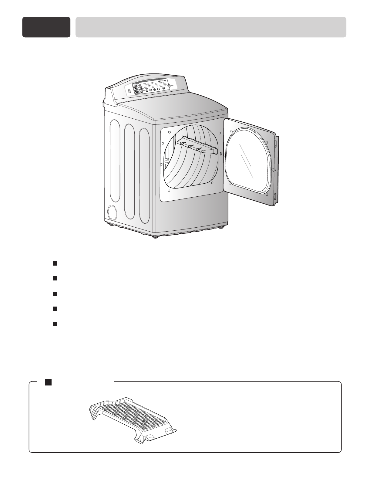
Part 1
SPECIFICATIONS
Type : Electric and Gas Dryer
Rating : 120V ~ 60 Hz 400W
Size : 68.6 cm x 73.7 cm x 111 cm
Capacity : 198 L
Weight : 57.2 kg
Specifications are subject to change by manufacturer.
ACCESSORIES
Dryer rack (1 each)
See page 26 for how to use.
3
Part 2
IMPORTANT WARRANTY AND SAFETY INSTRUCTIONS
SEEKING WARRANTY ASSISTANCE
The Warranty for your Dryer is located at the end of this manual. Warranty Service is
available by contacting your nearest LG Service Center. If this product is installed and
operated per this manual, LG will repair or replace any parts defective in material or
workmanship throughout the Warranty period, beginning the Date of Purchase.
WARNING!
For your safety, the recommendations in this manual must be followed. To reduce the risk
of fire or explosion, electric shock, or to prevent property damage, personal injury, or
death when using your appliance, follow basic precautions, including the following.
Warranty Restriction: If the dryer is subjected to other than private family use, all warranty
coverage is effective for only 90 days.
You will need the complete Model and Serial Number when requesting Warranty Service. Proof of
purchase date is required.
Use the space below to record the model number and serial number of your new LG dryer.
Model No.
Serial No.
Date of Purchase
Staple your receipt HERE.
4
Part 2
IMPORTANT WARRANTY AND SAFETY INSTRUCTIONS
IMPORTANT SAFETY INSTRUCTIONS
WARNING!
To help reduce any risk of electric shock, fire, or other personal or property injury
when using your dryer, please exercise care and follow basic safety precautions,
including the following:
1) Read all instructions before using the appliance.
2) Do not dry articles that have come into contact with
gasoline, dry-cleaning solvents, or other flammable
or explosive substances, as they give off vapors that
could ignite or explode.
3) Do not allow children to play on or in the appliance.
Close supervision of children is necessary when
using the appliance.
4) Before the appliance is removed from service or
discarded, remove the door to the drying
compartment.
5) Do not reach into the appliance if the drum is
moving.
6) Do not install or store this appliance where it will be
exposed to the weather.
7) Do not tamper with controls.
8) Do not repair or replace any part of the appliance or
attempt any servicing unless specifically
recommended in the user-maintenance instructions.
9) Do not use heat to dry articles containing foam
rubber or similarly textured rubber-like materials.
10) Clean lint screen before or after each load.
11) Keep area around the exhaust opening and adjacent
surrounding areas free from the accumulation of
lint, dust, and dirt.
12) The interior of the appliance and exhaust duct
should be cleaned periodically by qualified service
personnel.
13) Do not place items exposed to cooking oils in your
dryer. Items contaminated with cooking oils may
contribute to a chemical reaction that could cause a
load to catch fire.
14) Do not use fabric softners or products to eliminate
static unless recommended by the manufacturer of
the fabric softner or product.
SAVE THESE INSTRUCTIONS
GROUNDING INSTRUCTIONS
This appliance must be grounded. In the event of
malfunction or breakdown, grounding will reduce the
risk of electric shock by providing a path of least
resistance for electric current. This appliance is
equipped with a cord having an equipment-grounding
conductor and a grounding plug. The plug must be
plugged into an appropriate outlet that is properly
installed and grounded in accordance with all local
codes and ordinances.
WARNING - Improper connection of the equipment
grounding conductor can result in a risk of electric
shock. Check with a qualified electrician or service
person if you are in doubt as to whether the appliance is
properly grounded.
Do not modify the plug provided with the appliance: if
it will not fit the outlet, have a proper outlet installed by
a qualified electrician.
This appliance must be connected to a grounded metal,
permanent wiring system or an equipment-grounding
conductor must be run with the circuit conductors and
connected to the equipment-grounding terminal or lead
on the appliance.
5
Part 2
IMPORTANT WARRANTY AND SAFETY INSTRUCTIONS
WHAT TO DO IF YOU SMELL
GAS:
Do not try to light a match or cigarette, or turn
on any gas or electrical appliance.
Do not touch any electrical switches. Do not
use any phone in your building.
Clear the room, building or area of all
occupants.
Immediately call your gas supplier from a
neighbor’s phone. Follow the gas supplier’s
instructions carefully.
If you cannot reach your gas supplier, call the
fire department.
WARNING!
Keep flammable materials and vapors, such
as gasoline, away from dryer.
Place dryer at least 18 inches above the floor
for a garage installation.
Failure to do so can result in death,
explosion or fire.
WARNING
To reduce the risk of fire or explosion, electric
shock, property damage, personal injury or death
when using this appliance, please follow all
instructions and information, including those in
this manual and instructions and information
provided by your gas supplier, including the
following:
Do not store or use any gasoline, dry-cleaning
solvents any other flammable vapors or
liquids in the area surrounding this appliance.
Do not dry anything that has ever had anything
flammable on it, even after washing.
No washer can completely remove oil. Do not
dry any articles that have ever had any kind of
oil on them, including cooking oil.
Articles containing foam, rubber, rubber-like
materials, plastic or similar materials should be
dried on a clothesline or by using an air cycle.
Failure to follow these instructions can result in
fire, death or serious injury.
A qualified service person or company must
perform installation and service of this
appliance.
6
Part 3
INITIAL STEPS FOR INSTALLING YOUR DRYER
The following instructions will help guide you through the initial steps of setting up your dryer for use.
Please note that every section of this manual provides important information regarding the preparation and
use of your dryer, and it is important that you review this entire manual before proceeding with any
installation or use. More detailed instructions concerning electrical connections, gas connections, and
exhaust requirements are provided at other parts of this manual.
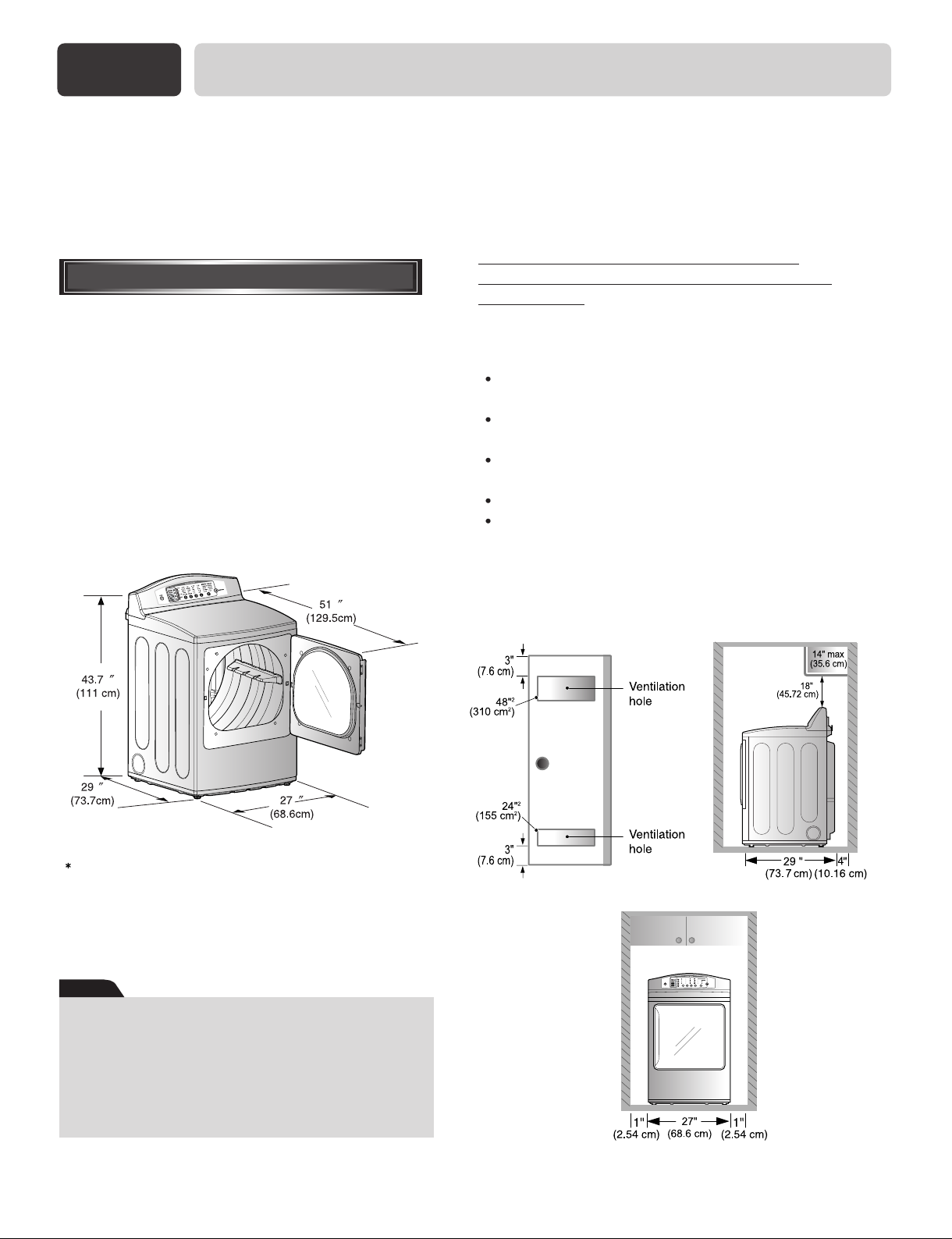
Certain minimum clearances are required
STEP 1
Choose a location with a solid floor for your dryer.
Place the dryer at least eighteen inches above the
floor for a garage installation. After placing the
dryer in the desired location, please make sure that
it has the required clearances shown below, and
sections on Exhaust and Maintenance requirements.
If you are installing your dryer in a manufactured or
mobile home, please refer to STEP 9 below for
additional instructions.
Positioning the Dryer.
above, behind, and to the sides of the unit, as
shown below.
are set forth in the picture below. Please also keep the
following instructions in mind when installing in a
closet or recessed area:
Consider allowing additional clearance for
installation and servicing.
Wall, door and floor molding may force additional
clearances.
An additional inch of clearance is recommended to
minimize noise transfer .
Consider space needed for companion appliances.
For closet installations, the picture below shows the
minimum required ventilation openings for the door.
A louvered door with comparable ventilation openings
is also acceptable.
Those required minimum clearances
Most installations require a minimum 5 1/2 in.
(14 cm) clearance behind the dryer for the exhaust
vent with elbow.
Note
Leveling legs should be secured.
All four legs are stably placed on the solid and
even floor.
If dryer is not level, laundry may not tumble
properly and sensor will not detect the accurate
humidity information.
When adjusting leveling, please be cautious not to
have serious injuries on your fingers and toes.
<Closet door> <Closet-Side view>
<Closet-Front view>
7
Part 3
Once in position, adjust the leveling legs of the dryer until it is level from left to right and from front to back.
The leveling leg must remain firmly on the floor and the dryer should not rock. The maximum slope of the dryer
from left to right or from front to back should not exceed 2.5 cm (1 inch). If the dryer is not level, and if the slope
exceeds 2.5 cm (1 inch), a load may not tumble properly and internal sensors may malfunction. Note: Other sections of this manual also provide important information concerning the placement of and clearances for your dryer.
Please review this entire manual before proceeding with any installation.
INITIAL STEPS FOR INSTALLING YOUR DRYER
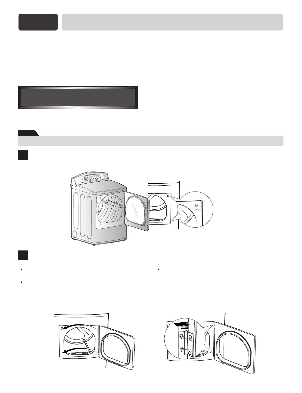
STEP 2
Procedure for Reversing
the Door
The door on your dryer can be installed to open either to the left or the right. Follow these procedures to reverse the
direction in which your door opens:
Note
Door and latch should be aligned at the center when closed. Otherwise, door is improperly closed and opened.
REMOVE FILLER PLUGS
1
Open the door and remove the filler plugs opposite the hinges.
REMOVE DOOR
2
With the door completely open, remove the BOTTOM
screw from each hinge on the dryer face.
Insert the screws about halfway into the TOP holes,
for each hinge, on the opposite side (where you
removed the filler plugs). Apply firm pressure to get
the screw started in new holes.
8
Loosen the TOP screw from each hinge on the dryer
face halfway. With one hand holding the top of the
door and the other hand holding the bottom, remove
the door from the dryer by lifting it UP and OUT.
Part 3
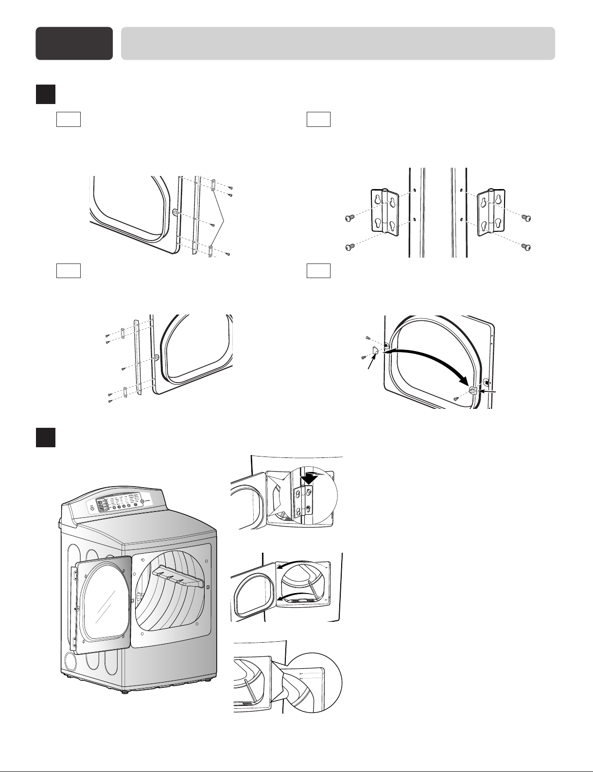
REMOVE AND REVERSE THE PARTS OF DOOR
3
INITIAL STEPS FOR INSTALLING YOUR DRYER
REMOVE HANDLE
3-1
Remove the screws holding the handle and two
spacers.
Rear of Door
REVERSE HANDLE
3-3
Install the handle on the opposite side of the
door
Rear of Door
spacers
REMOVE HINGES AND REHANG
3-2
DOOR
Remove the hinges from the door and install them on
the opposite side with the hinge pin toward the outside
of the door.
REWERSE DOOR DATCH
3-4
Remove the door catch and filler plate. Install them on
opposite sides of the door.
Filler
Plate
Opposite Side of
Door
Catch
REMOVE HINGES AND REHANG DOOR
4
Insert the door on the opposite side of the opening by moving the door IN and DOWN until the
top hinge and the bottom hinge are resting on the
top screws inserted in Step 2.
Tighten the two top screws of each hinge.
Reinsert the plastic plugs on the side from which
the door was removed.
Remove the remaining screws from the side of
the opening from which the door was removed.
With these screws, secure each hinge at the
bottom.
9
Part 3
INITIAL STEPS FOR INSTALLING YOUR DRYER
STEP 3
Connecting the Exhaust
and Venting System.
WARNING!
Use a heavy metal vent.
Do not use a plastic vent.
Do not use a metal foil vent.
Failure to follow these instructions can
result in death or fire.
Clean old ducts before installing this dryer
Note
Vent end will face to the outside home and
improper taping and unstable installation of vent
will cause undesirable drying performance.
In addition to the following warnings, please refer
to manual section on Exhaust Requirements and
Maintenance. IMPORTANT: To reduce the risk of
fire, combustion, and gas accumulation, the dryer
must be vented to the outdoors. Please follow the
instructions (and all others in this manual) very
carefully.
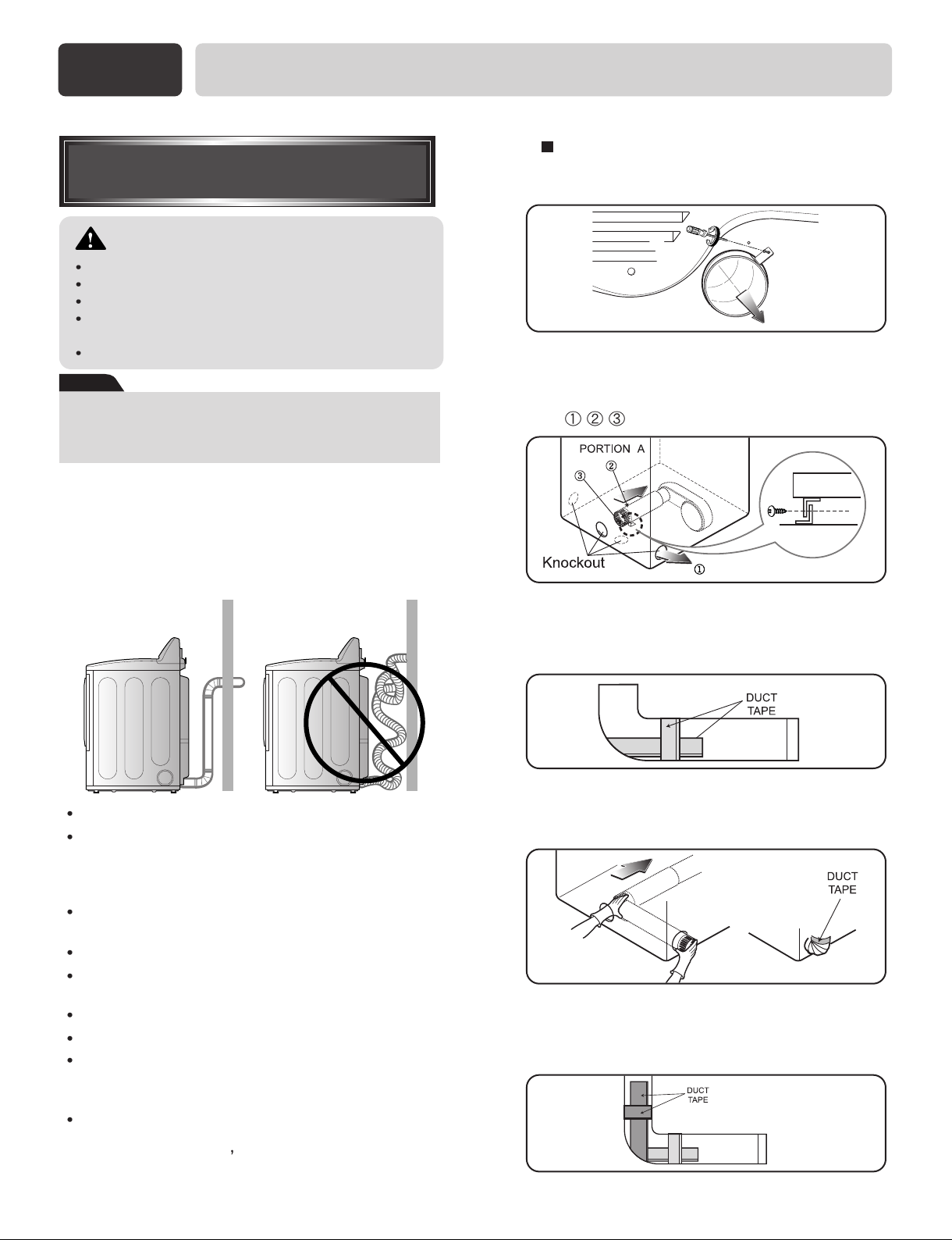
ALTERNATE EXHAUST DIRECTIONS
1.
Remove a screw and exhaust duct.
2-1.
Detach and remove the knockout that
matches the desired venting direction
(Right side not available on Gas Dryers)
, , the order of work.
2-2.
Reconnect the duct to the blower
housing and attach the duct to the
base.(Duct is a SVC part)
Do not use thin plastic or foil ducting.
Use 4" (10.2 cm) diameter rigid or flexible metal
duct (note: venting materials are not supplied with
the dryer, and you should obtain the venting
materials necessary for proper installation)
Position the Dryer such that the exhaust duct run is
as short as possible.
Clean old ducts before installing this dryer
The male end of each section of exhaust duct must
point away from the dryer
Use as few elbow joints as possible.
Use duct tape on all duct joints
Insulate ductwork that runs through unheated
areas in order to reduce condensation and lint
build-up on pipe walls; and
PLEASE BE AWARE THAT FAILURE TO
EXHAUST THE DRYER CORRECTLY WILL
VOID THE DRYER
10
S WARRANTY.
3-1.
Pre-assemble 4" elbow with 4" duct.
Wrap duct tape around joint.
3-2.
Insert elbow duct assembly first through the
side opening and connect the elbow to the
internal duct.
Part 3
INITIAL STEPS FOR INSTALLING YOUR DRYER
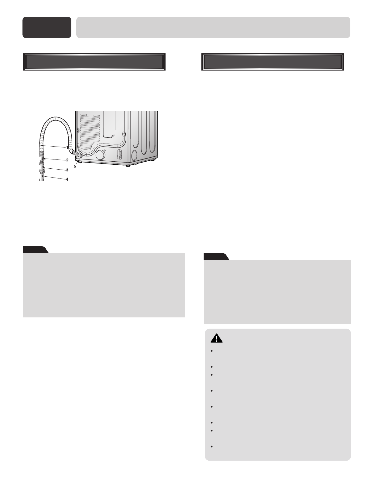
STEP 4
Connection of Gas Supply
(Gas dryer only). In addition to the following,
please refer to manual section on Gas Requirements
and Instructions.
1. New stainless steel flexible connector. Use this type of
connector only if allowed by local codes. Use Design AGA
Certified Connector.
2. 1/8" NPT Pipe Plug (for checking inlet gas pressure)
3. Equipment Shut-Off Valve-Installed
within 6’ (1.8 m) of dryer
4. Iron Pipe. Shorter than 20’ (6.1 m)
Use 3/8" pipe. Longer than 20’ (6.1 m) - Use 1/2" pipe.
5. 3/8" N.P.T. Gas Connection
Note
Make sure the burner nozzle is proper for the type of
gas you are provided with.
For instance, using LPG with LNG nozzle will result
in death, fire or explosion. Or using LNG with LPG
nozzle will not ignite burner.
If needed, nozzle conversion should be done by a
qualified service technician and mark or put the
label of the current type of nozzle on the dryer.
1. Confirm that the type of gas available in your laundry
room is appropriate for the dryer. The dryer is prepared
for Natural Gas with a 3/8" NPT gas connection.
2. Remove the shipping cap from the gas connection at the
back of the dryer. Make sure that you don’t damage the
threads of the gas connection pipe when you remove the
shipping cap.
3. Connect the dryer to your laundry room’s gas supply
using a new flexible stainless steel connector (as noted
below, only use a new stainless steel flexible connector
if allowed by your local codes).
4. Securely tighten all connections between the dryer and
your laundry room’s gas supply. Turn on your laundry
room’s gas supply and check all pipe connections (both
internal and external) for gas leaks with a non-corrosive
leak detection fluid. Refer to Part 7(page 20)
5. For LP (Liquefied Petroleum) gas connection, refer to
this manual’s section entitled Gas Requirements and
Instructions.
STEP 5
Following are several warnings and instructions
concerning making the electrical connection for electric
dryers. More detailed information concerning the
electrical connection is provided at the manual section
entitled Electrical Requirements For Electric Dryer and
it is important that you thoroughly review that section,
and the remainder of this manual, before taking any
steps to install or use this dryer.
1. Use only a new U.L. listed No. 10 (copper wire only)
three conductor power supply cord kit rated 240
Volts (minimum) 30 Amperes and labeled as suitable
for use in a clothes dryer.
2. Four-wire cord is required for manufactured (mobile)
home installations and use and where local codes do
not allow grounding of this appliance through
neutral.
3. Electrical Plug Connections.
4. For additional instruction on connecting the dryer to
an electrical power source, please refer to this
manual’s section on Electrical Requirements and
Electric Dryer.
Note
Burner input requirements
If your house is located at the elevation up to 10,000
feet.
Adjusting burner input setting is not needed in this
elevation because A.G.A certifies this dryer will not
have any problem with the B.T.U rating at this altitude.
If your house is at above 10,000 feet, you are required
to adjust a four percent(4%) reduction of the burner
B.T.U rating indicated on the model/serial rating plate.
Electrical Plug Connections
WARNING!
Use a new UL approved 30 amp power supply
cord or 10 gauge solid copper wire.
Use a UL approved strain relief.
Disconnect power before making electrical
connections.
Connect neutral wire(white or center wire) to
center terminal.
Ground wire(green or bare wire) must be
connected to green ground connector.
Securely tighten all electrical connections
See installation instructions for complete
instructions.
Failure to do so can result in fire or electrical
shock.
11
Part 3
INITIAL STEPS FOR INSTALLING YOUR DRYER
STEP 6
Prior to the first use of this appliance, use all-purpose
cleaning products or a solution of detergent
and water, with damp clothes to remove from the
inside of the dryer drum/drying compartment any
dust or dirt that may have accumulated the inside of
the dryer. Plug-in your dryer after reviewing the
following parts on your dryer’s Electrical
Requirements.
STEP 7
Preparation of the Dryer.
Confirming Heat Source
Operation.
Confirming Heat Source in Gas Dryers
Close the door to the dryer drum/drying
compartment and, after completing all steps in this
manual for proper installation of this dryer, start the
dryer on a heat setting, as described more fully in
the operating instructions that accompany the dryer.
After the dryer starts, the igniter will glow red and
the main burner will ignite.
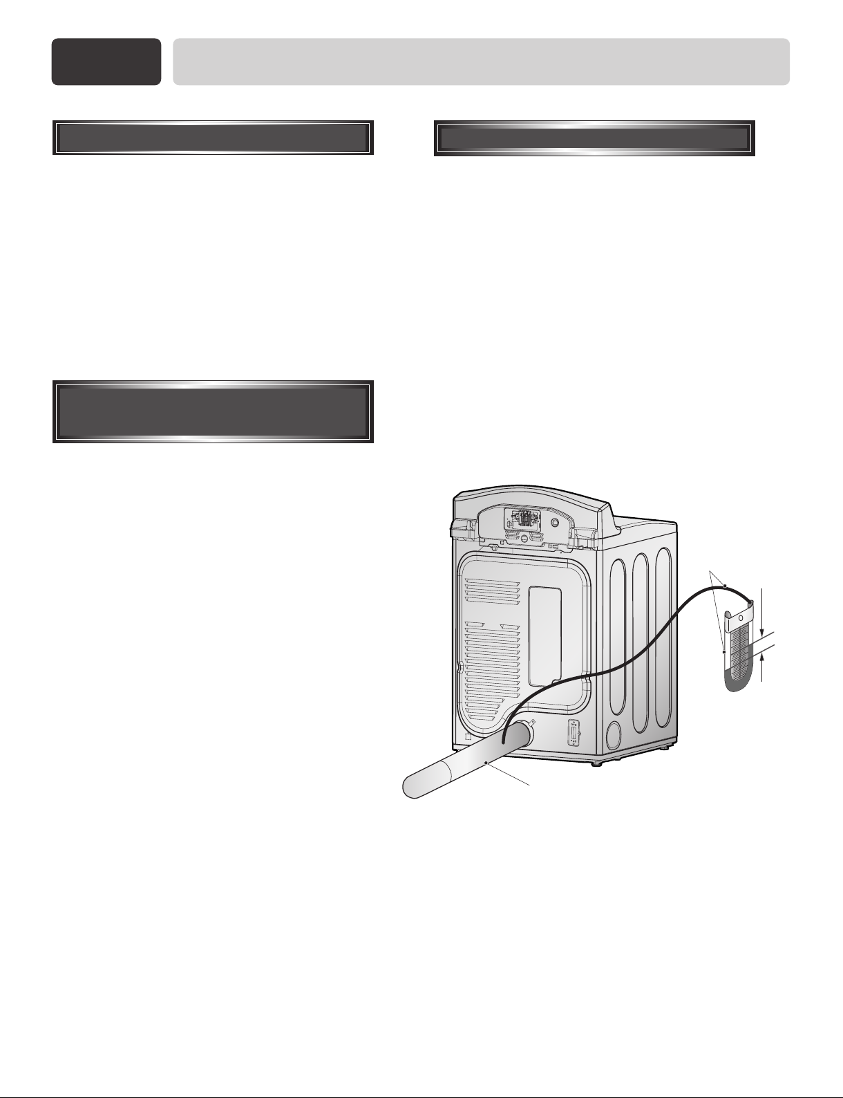
STEP 8
Effective dryer operation requires appropriate dryer
airflow. The adequacy of the airflow can be
measured by evaluating the static pressure. Static
pressure in the exhaust duct can be measured with a
manometer, placed on the exhaust duct
approximately 2 ft. (60.9 cm) from the dryer. Static
pressure in the exhaust duct should not exceed 0.6
inches (1.5 cm). The dryer should be checked with
the dryer running with no load.
Dryer Airflow.
Measuring Static pressure
Manometer
Warning: If all air is not purged from the gas line,
he gas igniter may go off before the gas and the
main burner have ignited. If this happens, the
igniter will re-attempt gas ignition after
approximately two minutes.
Confirming Heat Source in Electric Dryers
Close the door to the dryer drum/drying
compartment and, after completing all steps in this
manual for proper installation of this dryer, start the
dryer on a heat setting, as described more fully in
the operating instructions that accompany the dryer.
The exhaust air or the exhaust pipe should be warm
after the dryer has been operating for three minutes.
12
Exhaust Duct
MAXIMUM STATIC
PRESSURE IN
WATER COLUMN
0.6 inches (1.5 cm)

Part 3
STEP 9
INITIAL STEPS FOR INSTALLING YOUR DRYER
Additional Instructions
for Installation of Your
Dryer in a Manufactured
or Mobile Home.
4) Electric dryers may be vented to the outside
using the back, left, right, or bottom panel.
5) Gas dryers may be vented to the outside using the
back, left, or bottom panel. Gas dryer may not be
vented to the outside using the right side panel
because of the burner housing.
The following instructions are applicable to
installations of the dryer in a manufactured or
mobile home. Any installation in a manufactured or
mobile home must comply with the Manufactured
Home Construction and Safety Standards Title 24
CFR, Part 32-80 or Standard CAN/CSA0Z240 MH
and local codes and ordinances. If you are
uncertain whether your proposed installation will
comply with these standards, please contact a
service and installation professional for assistance.
The following instructions apply to any installation
of the dryer in a manufactured or mobile home:
1) The gas dryer must be permanently attached to
the floor.
2) The electrical connection for an electric dryer
must be a 4-wire connection. More detailed
information concerning the electrical connection
is provided at the manual section entitled
Electrical Requirements for Electric Dryer
6) The dryer exhaust duct must be affixed securely
to the manufactured or mobile home structure,
and the exhaust duct must be made of a material
that will resist fire and combustion, and it is
recommended that you use a rigid or flexible
metal pipe.
7) DO NOT connect the exhaust duct with any other
duct, vent, chimney, or other exhaust duct.
8) Make sure the dryer has adequate access to
outside fresh air to ensure proper operation. The
opening for outside fresh air must be at least 25
2
in
(163 cm2).
9) It is important that the clearance of the duct from
any combustible construction be at least 2 inches
(5 cm), and, when venting the dryer to the
outdoors, the dryer can be installed with a
clearances of 1 inch at the sides and back of the
dryer.
10) Please be aware that venting materials are not
supplied with the dryer. You should obtain the
venting materials necessary for proper
installation.
3) To reduce the risk of combustion and fire, the
dryer must be vented to the outside.
WARNING!
DO NOT connect exhaust ducts with
metal screws or fasteners that extend
into the duct.
WARNING!
DO NOT vent the exhaust duct under the
manufactured or mobile home.
13

Part 4
ELECTRICAL REQUIREMENTS FOR ELECTRIC DRYER
Following are additional instructions regarding electrical connections and requirements for electric dryers.
Important Warning:
must conform to the latest edition of the National Electrical Code, ANSI/NFPA 70 and all applicable local
regulations. Please contact a qualified electrician to check your home’s wiring and fuses to ensure that your home
has adequate electrical power to operate the dryer.
To help prevent fire, electric shock, serious injury or death, the wiring and grounding
120V/60Hz, 3-Wire Installation
Instructions for Grounding of your Electric
Dryer:
a) Please note that the wiring diagram is provided
Inside the dryer cabinet.
b) This dryer must be connected to a grounded
metal, permanent wiring system; or an
equipment-grounding conductor must be run
with the circuit conductors and connected to the
equipment-grounding terminal or lead on the
dryer.
d) The power cord (pigtail) connection between wall
receptacle and dryer terminal block IS NOT
supplied with dryer. Type of pigtail and gauge of
wire must conform to local codes and with
instructions mentioned on the following pages.
e) The method of wiring the dryer is optional and
subject to local code requirements. Refer to
examples on next page.
c) If branch circuit to dryer is fifteen feet (4.50 m)
or less in length, use U.L. (Underwriters
Laboratories) listed No. 10 A.W.G. wire
(copper wire only), or as required by local
codes. If over fifteen feet (4.50 m), use U.L.
(Underwriters Laboratories) listed No. 8
A.W.G. wire (copper wire only), or as required
by local codes. Allow sufficient slack in wiring
so dryer can be moved from its normal location
when necessary.
f) You must select the method by which to wire
your dryer according to local code and ordinance
requirements. Sample methods are included in
the following pages.
WARNING!
Label all wires prior to disconnection
when servicing the dryer, because
wiring errors can cause serious injury
to you and your dryer.
14
Part 4
Black
White Red
Center terminal block
screw(silver)
Neutral grounding
wire(white)
Neutral wire
(white or center wire)
Strain relief
Green wire of power cord
External ground connector
ELECTRICAL REQUIREMENTS FOR ELECTRIC DRYER
Review the following options to determine the appropriate electrical connection
for your home:
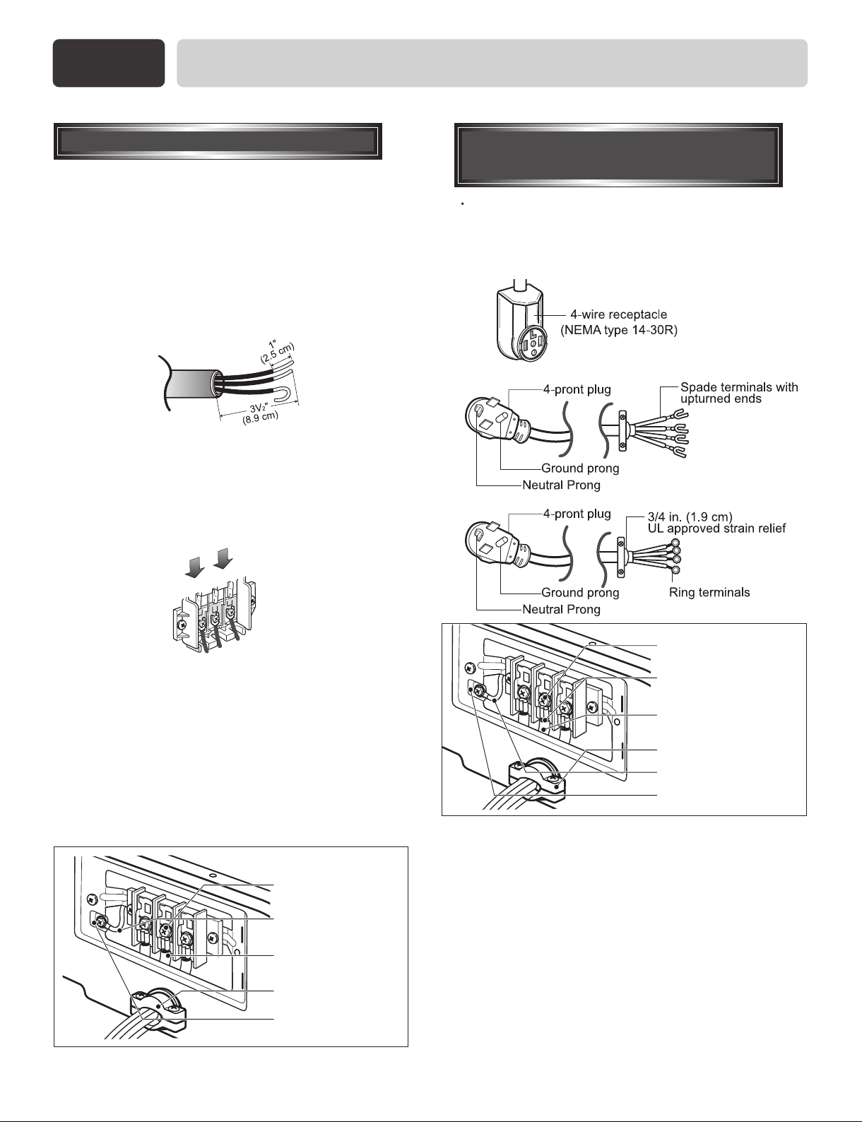
4-wire receptacle
(NEMA type14-30R)
Use the instructions at this section if your home has
a 4-wire receptacle (NEMA type 14-30R) and you
will be using a UL listed, 120/240 volt minimum,
30 amp, dryer power supply cord.
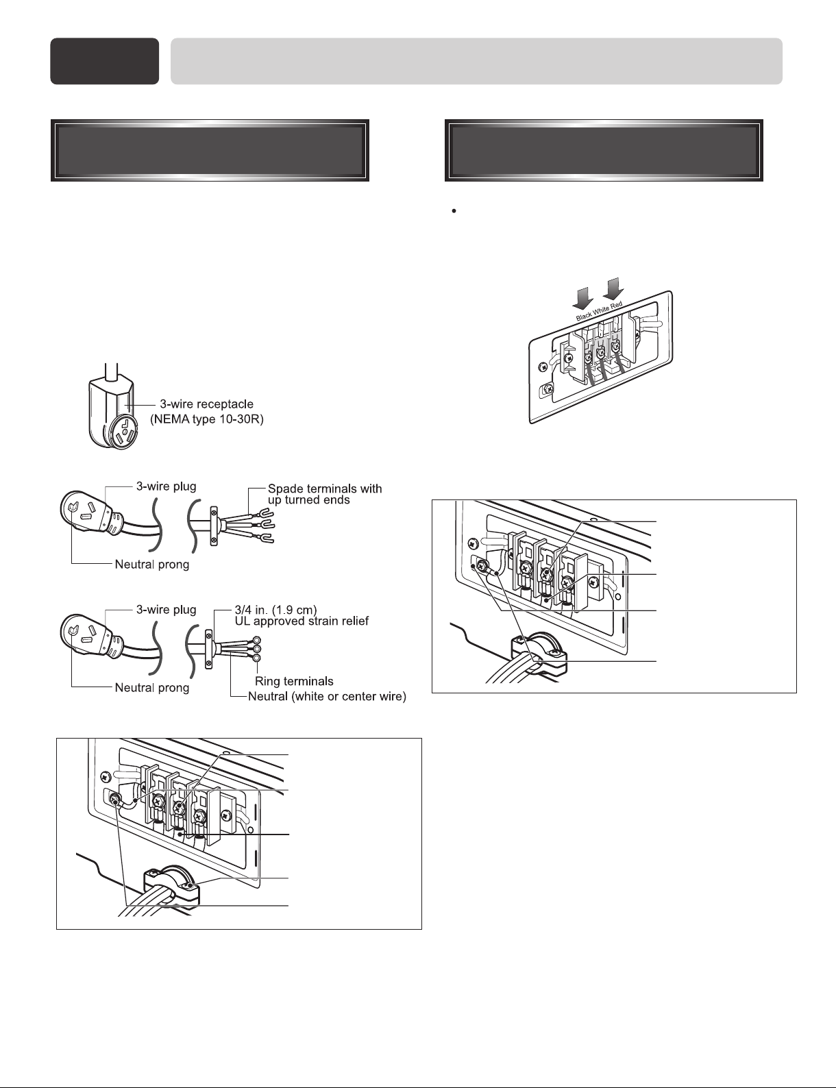
3-wire receptacle
(NEMA type10-30R)
Use the instructions at this section if your home has
a 3-wire receptacle (NEMA type 10-30R) and you
will be using a UL listed, 120/240 volt minimum,
30 amp, dryer power supply cord.
4-wire direct
If this type is available at your home. you will be
connecting to a fused disconnect or circuit breaker
box
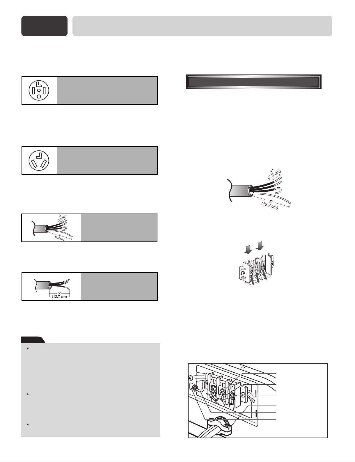
4-wire connection : Direct wire
Important : use 4-wire connection in the places such
as mobile homes and areas where 3-wire connections
is not available.
Prepare minimum 5ft(1.52m) of length in order for
dryer to be replaced.
First, peel 5 inch (12.7cm) of covering material from
end. Make a 5 inch of ground wire bared. After cutting
1
/2 inch (3.8cm) from 3 other wires. peel insulation
1
back 1inch (2.5cm). Make ends of 3 wires a hook
shape.
Then, put the hooked shape end of the wire under the
screw of the terminal block(hooked end facing rightward)
and pinch the hook together and screw tightly.
3-wire direct
If this type is available at your home. you will be
connecting to a fused disconnect or circuit breaker
box
Note
Screw power supply wire to the terminal block.
Colored wire should be connected to same color
screw. Wire color indicated on manual is
connected to the same color screw in block.
Otherwise, excessive current is applied resulting
in damages on product and heating failure.
Appropriate screwing is essential. Imcomplete
screwing also may cause loose connection or
unscrewing because of excessive screw
abrasion.
Loose screwing may cause connection error,
which result in death, fire or serious injury.
1. Connect neutral wire(white) of power cord to center
terminal block screw.
2. Connect red and black wire to the left and right
terminal block screws.
3. Connect ground wire(green) of power cord to external
ground screw and move neutral ground wire of
appliance and connect it to center screw.
4. Make sure that the strain relief screw is tightened.
and be sure that all terminal block nuts are on tight and
power cord is in right position.
15
Part 4
Black
White Red
Center terminal
block screw(silver)
Neutral grounding
wire(white)
Neutral grounding
wire(white)
Strain relief
External ground
connector
Center terminal block
screw(silver)
Neutral grounding
wire(white)
Neutral wire
(white or center wire)
Strain relief
Green wire of power cord
External ground connector
ELECTRICAL REQUIREMENTS FOR ELECTRIC DRYER
3-wire connection : Direct wire
Important : use 3-wire connection in the places
such as mobile homes and areas where 3-wire
connections is not available.
Prepare minimum 5ft(1.52m) of length in order for
dryer to be replaced.
First, peel 3
from end and bare 1 inch from the ends.
Then, put the hooked shape end of the wire under
the screw of the terminal block(hooked end facing
rightward) and pinch the hook together and screw
tightly.
1
/
2
inch (8.9cm) of covering material
Option 1:
4-wire connection with
a Power supply cord.
lf your local codes or ordinances do not allow the
use of a 3 wire connection, or you are installing
your dryer in a mobile home, you must use a 4wire connection.
1. Connect neutral wire(white) of power cord to
center terminal block screw.
2. Connect red and black wire to the left and right
terminal block screws.
3. Make sure that the strain relief screw is tightened
and be sure that all terminal block nuts are on
tight and power cord is in right position.
16
1. Connect neutral wire(white) of power cord to
center terminal block screw.
2. Connect red and black wire to the left and right
terminal block screws.
3. Connect ground wire(green) of power cord toexternal ground screw and move neutral groundwire of
appliance and connect it to center screw.
4. Make sure that the strain relief screw is tightened.
and be sure that all terminal block nuts are on tight
and power cord is in right position.
Part 4
Center terminal
block screw(silver)
Neutral grounding
wire(white)
Neutral grounding
wire(white)
Strain relief
External ground
connecter
ELECTRICAL REQUIREMENTS FOR ELECTRIC DRYER
Option 2:
3-Wire Connection with
a Power Supply Cord
lf your local codes or ordinances permit the
connection of a frame-grounding conductor to the
neutral wire, use these instructions. If your local
codes or ordinances do not allow the connection of
a frame-grounding conductor to the neutral wire,
use the instructions under Section 3: Optional
3-wire connection.
Option 3:
Optional 3-wire
connection.
If your local codes or ordinances do not allow the
connection of a frame-grounding conductor to the
neutral wire, use the instructions under this
section.
Neutral grounding
wire(Green)
Neutral wire(white)
External ground
connector
Separate ground
wire
1. Connect neutral wire(white) of power cord to
center terminal block screw.
2. Connect ground wire of appliance and neutral
wire of power cord to center terminal block
screw.
3. Connect red and black wire to the left and right
terminal block screws.
4. Make sure that the strain relief screw is tightened.
and be sure that all terminal block nuts are on
tight and power cord is in right position.
5. Connect a independent ground wire from external
ground connector to proper ground.
17
Part 5
120
120
120
ELECTRICAL REQUIREMENTS FOR GAS DRYERS
120Volt, 60 Hertz, with 3-Prong Grounding Plug
Following are additional instructions regarding electrical connections and requirements for gas dryers.
Important Warning: To help prevent fire, electric shock, serious injury or death, the wiring and grounding
must conform to the latest edition of the National Electrical Code, ANSI/NFPA 70, or the Canadian Electrical
Code, CSA C22.1, and all applicable local regulations. Please contact a qualified electrician to check your home’s
wiring and fuses to ensure that your home has adequate electrical power to operate the dryer.
Electrical Requirements for Your Dryer:
a) Please note that the wiring diagram is provided
inside the dryer control hood. Label all wires
prior to disconnection when servicing the dryer,
because wiring errors can cause serious injury to
you and your dryer.
b) Use separately fused circuits for washers and
dryers, and DO NOT operate a washer and a
dryer on the same circuit.
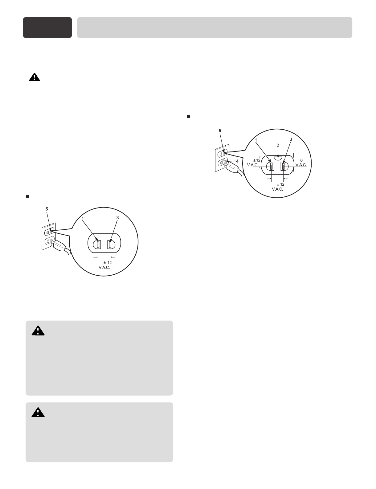
NONE GROUND TYPE
If the AC current outlet has a ground terminal, then
sep arate grounding is not required. Note that AC
power out let configurations may differ from country
to country.
WARNING!
Do not overload the circuit by operating
other appliances on the same circuit when
this appliance is operating, by using an
extension cord to connect the dryer to the
power source, or by using any adapter to
allow additional cords to connect to the
same outlet.
WARNING!
DO NOT modify the plug provided with
the dryer. If it does not fit the outlet in your
laundry room, a proper outlet will need to be
installed in your laundry room by a qualified
service person or company.
18
GROUND TYPE
STANDARD 120VOLT, 60 HERTZ, 3-WIRE
EFFECTIVITY GROUNDED CIRCUIT
1 L1
2 Ground
3 Neutral Side
4 Round Grounding Prong
5 Neutral
a) The dryer has a three-prong plug to help guard
against shock. The plug should be plugged
directed into a properly grounded three-prong
receptacle that is rated 120 Volts AC (alternating
current) 15 Amps. This plug, in order to be
properly and fully effective, must be plugged into
a properly installed outlet that is grounded in
accordance with all local codes and ordinances.
b) The dryer must be grounded in order to reduce
the risk of electric shock, including a
malfunction or breakdown.
c) If your laundry room does not meet the
specifications required by this manual, or if you
are uncertain whether or not your laundry room
meets these specifications, please have a
qualified service person or company, for example
a qualified electrician or your local electric
company, review your laundry room’s electrical
supply for any problems.
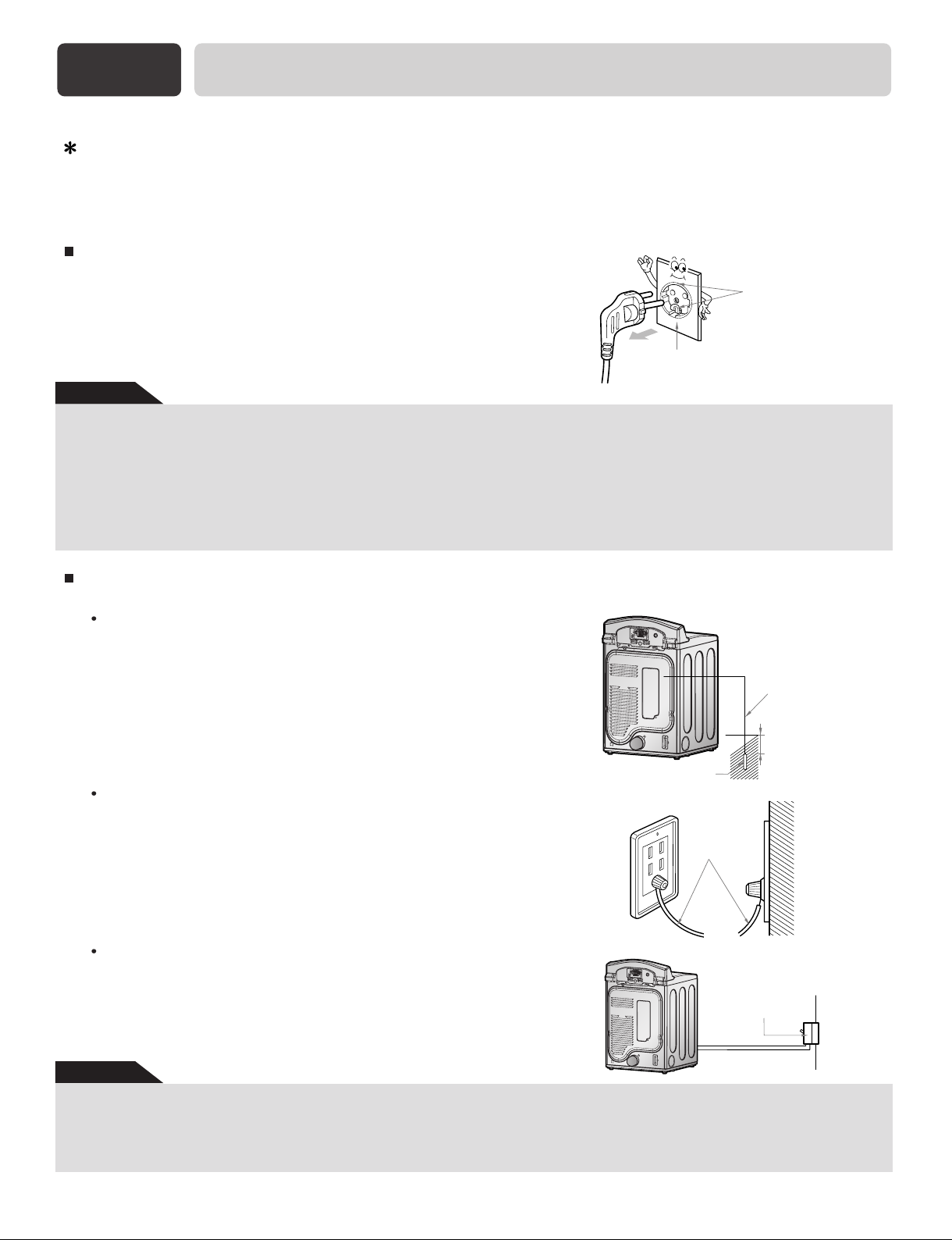
Part 5
Ground
Terminal
Outlet with ground terminal.
Ground Wire
Ground Copper Plate
75cm
Ground
Wire
Short-circuit
breaker
ELECTRICAL REQUIREMENTS FOR GAS DRYERS
Grounding Method with Ground insert space Terminal
Earth wire should be connected.
If the earth wire is not connected, there is possible a danger of electric shock caused by the current leakage .
Grounding Method with Ground insert space Terminal
If the AC current outlet has a ground terminal, then separate grounding
is not required. Note that AC power outlet configurations may differ
from country to country.
Caution
CAUTION concerning the Power Cord
Most appliances recommend they be placed upon a dedicated circuit; that is, a single outlet circuit which powers only that appliance and has
no additional outlets or branch circuits. Check the spercification page of this owner's manual to be certain. Do not overload wall outlets.
Overloaded wall outlets, loose or damaged wall outlets, extension cords, frayed power cords, or damaged or cracked wire insulation are dangerous. Any of theseconditions could result in electric shock or fire. Periodically examine the cord of your appliance, and if its appearance
indicates damage or deterioration, unplug it, discontinue use of the appliance, and have the cord replaced with an exact replacement part by
an authorized servicer. Protect the power cord form physical or machanical abuse, such as being twisted, kinked, pinched, colsed in a door,
or walked upon. Pay particular attention to plugs. wall outlets, and the point where the cord exits the appliance.
Other Grounding Method
Burying Copper Plate
Connect the Ground Wire to a Ground Copper Plate and bury it more
than 75cm in the ground.
Using Ground Wire
Connect the Ground Wire to a the socket provided
exclusively for grounding
Using a Short Circuit Breaker
If grounding methods described above are not possible, a separate circuit breaker should be employed and installed by a qualified electrician
Caution
• To prevent a possible explosion, do not connect ground to a gas pipe.
• Do not connect ground to telephone wires or lightning rods. This may be dangerous during electrical storms.
• Connecting ground to plastic has no effect.
• Ground wires should be connected when an extension cord is used.
19
Part 6
Following are important instructions and information concerning the requirements for the gas supply and service for
gas dryers.
Important Warning: The gas supply and service for a gas dryer must comply with all local codes
and ordinances. In the absence of any local codes or ordinances in your area, the gas supply and service for your gas
dryer must comply with the latest edition of the National Fuel Gas Code, ANSI Z223.1/NFPA 54.
1. Gas supply requirements: Liquefied Petroleum
(L.P.) Gas (2,500 Btu/ft3 (93.1 MJ/m3)) service
must be provided at 10 + 1.5 in. water column
pressure.
2. Do not attempt to connect Dryer to Liquified
Petroleum (LP Gas) Gas service without a
qualified professional.
3. Isolate the dryer from the gas supply piping
system by closing its individual manual shut-off
valve, during any pressure testing of the gas
supply system at test pressure equal to or less
than 2/1 psi (3.45 kPa).
4. Supply Line Requirements. Your laundry room
must have a rigid gas supply line to your dryer.
In the United States, an individual manual shutoff
valve MUST be installed within at least 6 feet
(1.8m) of the dryer, in accordance with the
National Fuel Gas Code ANSI Z223.1. A 1/8 in.
N.P.T. pipe plug must be installed as shown.
GAS REQUIREMENTS AND INSTRUCTIONS
5. If using a rigid pipe, the rigid pipe should be 1/2
inch IPS. If acceptable under local codes and
ordinances and when acceptable to your gas
supplier, 3/8 inch approved tubing may be used
where lengths are less than 20 feet (6.1m).
Larger tubing should be used for lengths in
excess of 20 feet (6.1m). It is also important that
you use pipe joint compound that is insoluble in
LP gas.
6. To reduce the danger of gas leaks, explosion, and
fire, please follow and observe the following
Instructions and WARNINGS:
• Connect the dryer to the type of gas shown on the
nameplate;
• Use new flexible stainless steel connectors;
• Use Teflon tape and pipe joint compound
insoluble in LP gas on all pipe threads;
• Purge gas supply of air and sediment before
connecting the gas supply to the dryer; in order to
prevent gas valve contamination, before tightening
connection between gas supply and dryer, purge
remaining air until odor of gas is identified; and
WARNING!
DO NOT attempt any disassembly of the
dryer, any disassembly requires the
attention and tools of an authorized and
qualified service person or company.
20
• DO NOT use an open flame to inspect for gas
leaks; instead, use a non-corrosive leak detection
fluid.
WARNING!
Use a new AGA or CSA approved gas
supply line.
Install a shut-off valve.
Securely tighten all gas connections.
If connected to LP, have a qualified person
make sure gas pressure does not exceed
13 in. water column.
Examples of a qualified person include
licensed heating personnel, authorized gas
company personnel, and authorized service
personnel.
Failure to do so can result in death,
explosion, or fire.
 Loading...