

LG TCW2013QS1, TCW2013CS1, TCW2013QS2, TCW2013CS2, TCW2013LS2 Service Manual

CONFIDENTIAL
WASHING MACHINE
SERVICE MANUAL
CAUTION
READ THIS MANUAL CAREFULLY TO DIAGNOSE
PROBLEMS CORRECTLY BEFORE SERVICING THE UNIT.
MODEL : TCW2013QS1 / TCW2013CS1
Any reproduction, duplication, distribution (including by way of email, facsimile or other electronic means),
publication, modification, copying or transmission of this Service Manual is STRICTLY PROHIBITED unless you
have obtained the prior written consent of the LG Electronics entity from which you received this Service
Manual. The material covered by this prohibition includes, without limitation, any text, graphics or logos in this
Service Manual.
Copyright © 2016 - 2017 LG Electronics Inc. All rights reserved. Only training and service purposes.

CONTENTS
1.IMPORTANT SAFETY INSTRUCTIONS ............................................................................. 3
2. SPECIFICATIONS ............................................................................................................... 4
3. FEATURES AND TECHNICAL EXPLANATION .................................................................. 5
4. PARTS IDENTIFICATION ..................................................................................................... 7
5. INSTALLATION INSTRUCTIONS ........................................................................................ 8
6. OPERATION ................................................................................................................ 14~17
7. WIRING DIAGRAM/PROGRAM CHART/PCB LAYOUT ............................................. 18~20
8. TROUBLESHOOTING .................................................................................................. 21~24
8-1. BEFORE PERFORMING SERVICE ......................................................................... 21
8-2. QC TEST MODE . ..................................................................................................... 21
8-3. HOW TO CHECK THE WATER LEVEL FREQUENCY ............................................ 21
8-4. HOW TO CHECK THE RPM ..................................................................................... 21
8-5. ERROR DISPLAY ............................................................................................... 22~23
8-6. DISPENSER .............................................................................................................. 24
9. DIAGNOSIS AND TROUBLESHOOTING .................................................................. 25~37
10. DISASSEMBLY INSTRUCTIONS .............................................................................. 38~46
11. EXPLODED VIEW ............................................................................................................ 47
11-1-1. CABINET & CONTROL PANEL ASSEMBLY - COIN TYPE ................................ 47
11-1-2. CABINET & CONTROL PANEL ASSEMBLY - CARD TYPE ............................... 48
11-1-3. CABINET & CONTROL PANEL ASSEMBLY - OPL TYPE .................................. 49
11-2. DRUM & TUB ASSEMBLY ...................................................................................... 50
11-3. DISPENSER ASSEMBLY ....................................................................................... 51
Copyright © 2016 - 2017 LG Electronics Inc. All rights
reserved. Only training and service purposes.
2
1. IMPORTANT SAFETY INSTRUCTIONS
!
!
!
READ ALL INSTRUCTIONS BEFORE USE
WARNING
For your safety, the information in this manual must be followed to minimize the risk of fire
or explosion, electric shock, or to prevent property damage, injury to persons, or death.
IMPORTANT SAFETY INSTRUCTIONS
WARNING: To reduce the risk of fire, electric shock, or injury to persons when using the washer, follow basic
precautions, including the following:
¥ Read all instructions before using the washer.
¥ Do not wash articles that have been previously
cleaned in, washed in, soaked in, or spotted with
gasoline, dry cleaning solvents, or other
flammable or explosive substances, as they give
off vapors that could ignite or explode.
¥ Do not add gasoline, dry cleaning solvents, or
other flammable or explosive substances to the
wash water. These substances give off vapors that
could ignite or explode.
¥ Under certain conditions, hydrogen gas may be
produced in a hot water system that has not been
used for 2 weeks or more. HYDROGEN GAS IS
EXPLOSIVE. If the hot water system has not been
used for such a period, before using the washing
machine, turn on all hot water faucets and let the
water flow from each for several minutes. This will
release any accumulated hydrogen gas. As the
gas is flammable, do not smoke or use an open
flame during this time.
¥ Do not allow children to play on or in the washer.
Close supervision of children is necessary when
the washer is used near children.
¥ Before the washer is removed from service or
discarded, remove the door to prevent children
from hiding inside.
¥ Do not install or store the washer where it will be
exposed to the weather.
¥ Do not tamper with controls.
¥ Do not repair or replace any part of the washer or
attempt any servicing unless specifically
recommended in the user-maintenance
instructions or published user-repair instructions
that you understand and have the skills to carry
out.
¥ See Installation Instructions for grounding
requirements.
¥ ALWAYS follow the fabric care instructions
supplied by the garment manufacturer.
¥ Do not place items exposed to cooking oil in your
washer. Items contaminated with cooking oils may
contribute to a chemical reaction that could cause
a load to catch fire.
¥ Do not use fabric softeners or products to
eliminate static unless recommended by the
manufacturer of the fabric softener or product.
SAVE THESE INSTRUCTIONS
GROUNDING INSTRUCTIONS
This appliance must be grounded. In the event of malfunction or breakdown, grounding will reduce the risk
of electric shock by providing a path of least resistance for electric current. This appliance is equipped with
a cord having an equipment-grounding conductor and grounding plug. The plug must be plugged into an
appropriate outlet that is properly installed and grounded in accordance with all local codes and ordinances.
¥ Do not use an adapter or extension cord.
¥ Do not remove ground prong.
¥ If you don’t have the proper outlet, consult an electrician.
WARNING: Improper connection of the equipment-grounding conductor can result in risk of electric shock.
Check with a qualified electrician or serviceman if you are in doubt as to whether the appliance is
properly grounded. Do not modify the plug provided with the appliance - if it does not fit the outlet,
have a proper outlet installed by a qualified electrician.
3

2. SPECIFICATIONS
MODEL
COLOR
POWER SUPPLY
PRODUCT WEIGHT
ELECTRIC
POWER
CONSUMPTION
REVOLUTION
SPEED
CYCLES
OPTIONS
OPERATIONAL WATER PRESSURE
CONTROL TYPE
WASH CAPACITY
DIMENSIONS
WASHING
DRAIN PUMP
CIRCULATION PUMP
WASH
SPIN
TCW2013QS1 / TCW2013CS1
STAINLESS SILVER
AC 120V, 60Hz
223.1 lbs.(101.2 kg)
500W
80W
30W
45 rpm
980 RPM
4
Card&Coin : ADD SUPER WASH Cycle / OPL : CUSTOM Mode
20 - 120 psi (138 ~ 827 kPa)
Electronic
5.2 cu.ft (IEC:6.0 cu.ft)
73.7 cm (W)X 81.4 cm (D)X 103.6 cm (H), 137 cm (D with door open)
29 ”(W)X 32 ”(D)X 40.8 ”(H), 53 ”(D with door open)
DOOR SWITCH TYPE
WATER LEVEL
LAUNDRY LOAD SENSING
ERROR DIAGNOSIS
PTC + Solenoid
10 steps (by sensor)
Incorporated
Incorporated
4
3. FEATURES & TECHNICAL EXPLANATION
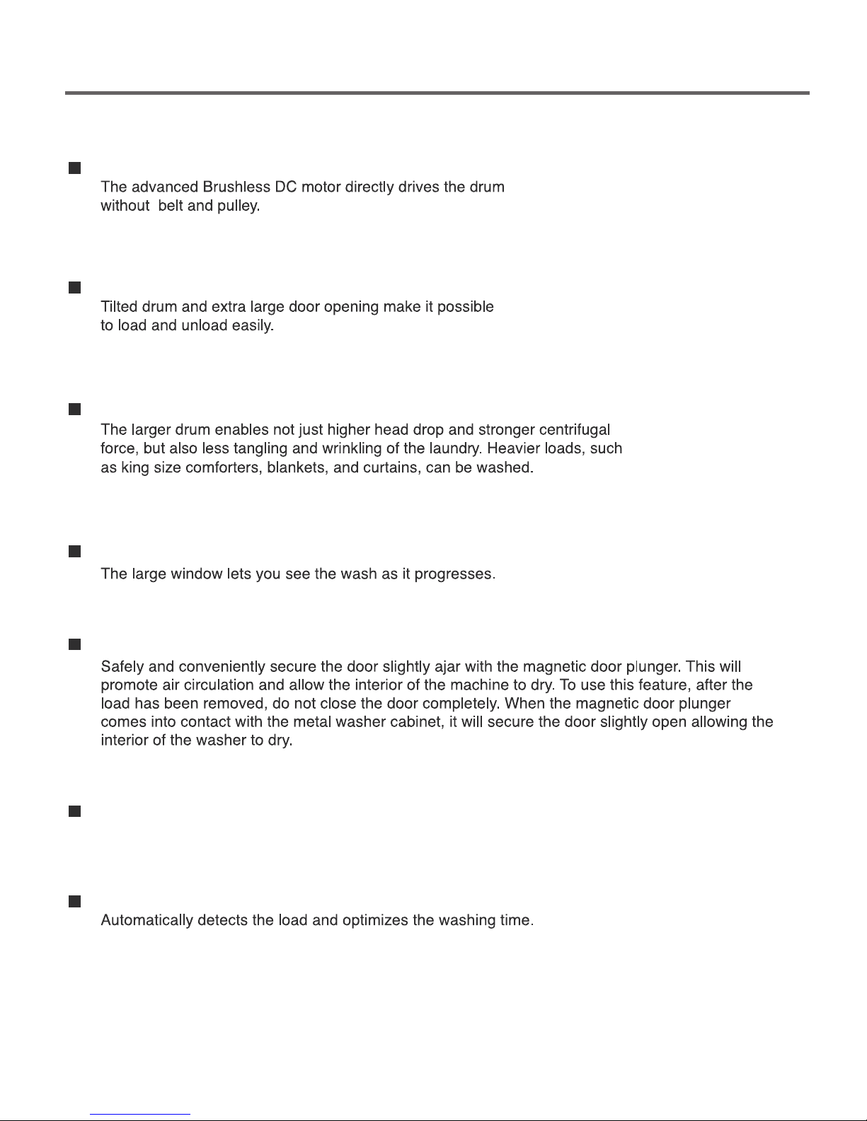
Direct Drive System
The Tilted Drum and Extra La
Ultra Capacity
Large Door and Window
The Stainless Steel drum
Magnetic Door Plunger
rge Door Opening
Automatic Wash Load Detection
3-1. FEATURES
5
6
)
)
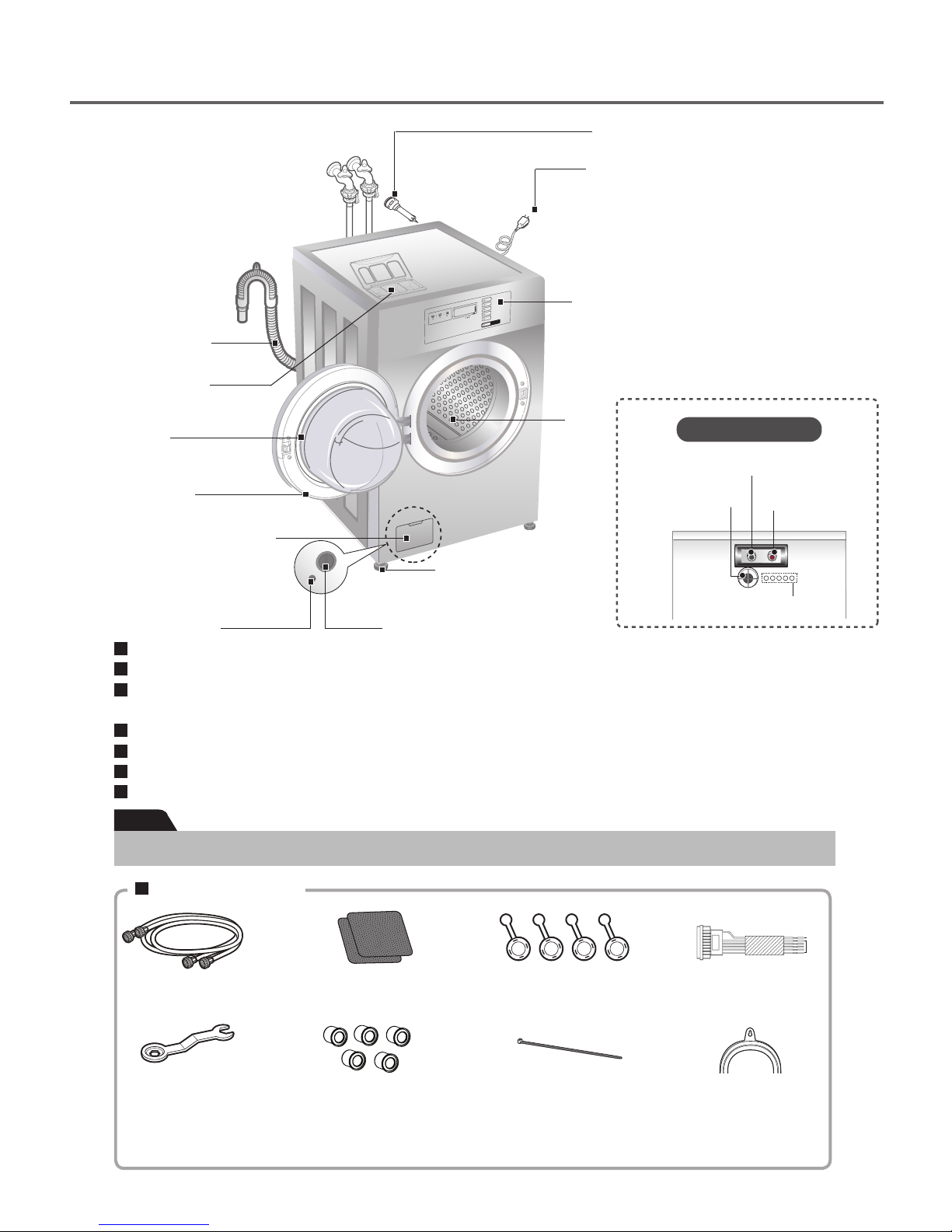
4. PARTS IDENTIFICATION
Drain Hose
Dispenser
Shipping Bolts (4)
Power Plug
•
If the supply cord is damaged,
it must be replaced by the
manufacturer or an authorized
service technician in order to
avoid a hazard.
Control Panel
Door
Magnet Door
Plunger
(see page 5)
Drum
Air Vent for Safety
Back of Washer
Cold Water Inlet
Hot Water Inlet
Lower Cover Cap
Adjustable Feet
Auto dosing hole
Drain Plug
Name: Front-loading Washing Machine
Power supply: 120V, 60Hz
Size: 73.7 cm (W)X 81.4 cm (D)X 103.6 cm (H),137 cm (D with door open)
29 ”(W)X 32 ”(D)X 40.8”(H),53" (D with door open)
Weight: 223.1 lbs. (101.2 kg)
Wash capacity: 5.2 cu.ft (IEC:6.0 cu.ft)
Spin speed: 980 RPM
Permissible water pressure: 20 - 120psi (138 ~ 827 kPa)
Note
Specifications subject to change by manufacturer.
Drain Pump Filter
Accessories
Hot and Cold
Water Hoses
Wrench
(for removing
shipping bolts and
adjusting leveling
feet)
(for securing auto
Non-skid pads
Hole caps (5)
dosing hole)
Caps (4)
(for covering
shipping bolt holes)
Tie Strap
(for securing drain
hose)
7
((+
Harness
(for connecting
auto dosing)
Elbow Bracket
(for securing drain
hose)
5. INSTALLATION INSTRUCTIONS
Wrench
!
WARNING
· Washer is heavy. Two or more people may be needed to install and move the appliance.
Failure to do so can result in back or other injury.
· Store and install the washer where it will not be exposed to temperatures below freezing or exposed to
outdoor weather conditions. Failure to follow this warning can cause serious injury, fire, electric shock, or
death.
· This appliance must be properly grounded for personal safety. Properly ground washer to conform with
all governing codes and ordinances. Failure to follow this warning can cause serious injury, fire, electric
shock, or death.
· Do not install the washer in humid spaces to reduce the risk of electric shock. Failure to follow this
warning can cause serious injury, fire, electric shock or death.
· The base opening must not be obstructed by carpeting when the washer is installed on a carpeted floor.
· Do not remove ground prong. Do not use an adapter or extension cord. Plug into a grounded 3 prong
outlet. Failure to follow this warning can cause serious injury, fire, electric shock or death.
· Keep the area underneath and around your appliances free of combustible materials such as lint,
paper, rags, chemicals, etc. Failure to do so can result in fire.
· To reduce the risk of injury to persons, adhere to all industry recommended safety procedures including the
use of long sleeved gloves and safety glasses. Failure to follow all of the safety warnings in this manual could
result in property damage, injury to persons or death.
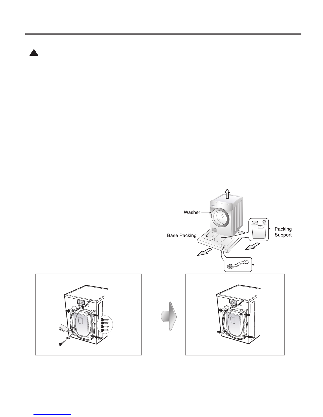
■ Shipping bolts
The appliance is fitted with shipping bolts to
prevent
internal damage during transportation.
Packing and all shipping bolts must be removed
before using the washer.
☞ When unpacking the base, be sure to remove
the additional packing support in the middle of
the base packing.
■ Removing shipping bolts
CAP
Unscrew the 4 bolts with the wrench supplied
Take out the 4 bolts by twisting the braces slightly
※ Keep the
(Whenever the appliance is transported, the
shipping bolts and braces must be replaced.)
4 bolts and the wrench for future use
Close the holes with the caps supplied.
8
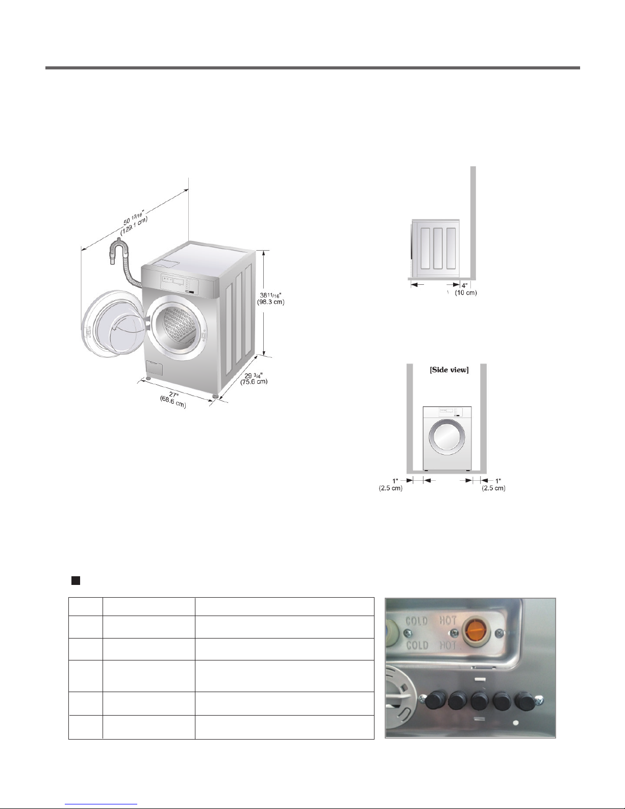
■ Installation clearances
32 ”
(81.4 cm)
32 ”
(81.4 cm)
29 ”
(73.7 cm)
The location must be large enough to open
the washer door completely.
■ Washer dimensions
■ Minimum installation spacing for
recessed area installation.
Side view
The following dimensions shown are for the minimum
spacing allowed.
Additional spacing should be considered for installation and
servicing.
· Additional clearances might be required for wall, door, and
floor moldings.
· Additional spacing of 4″(10 cm) on back,
1″(2.5 cm) on all sides of the washer is recommended to
reduce noise transfer.
Companion appliance spacing should also be considered.
Installation of Auto dosing system
CH
①
②
③
④
⑤
Detergent
ETC (Emulsifier)
Main wash
Bleach
Softener
Pre-wash
(Remaining washing time : 5 Minutes)
Input period
Main wash phase
Main wash phase
Main wash
Final rinse phase
Pre-wash phase
Front view
⑤ ④ ③ ② ①
9
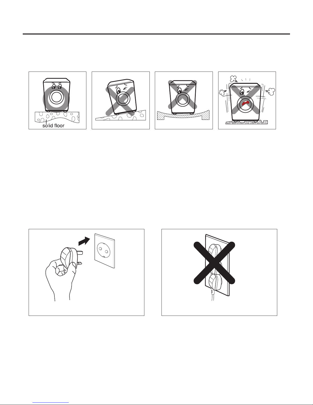
■
INSTALL THE APPLIANCE
ON A FLAT AND FIRM SURFACE
■ Level floor
· Allowable slope under entire washer is 1¡.
· To minimize noise and vibration, the washer
MUST be installed on a solidly constructed
floor.
· Carpeting and soft tile surfaces are not
recommended.
· Never install the washer on a platform or
weakly supported structure.
■
CONNECT POWER PLUG
NOTE: A firm, solid floor is even more critical to a
front-loading washer than to a top-loader.
If your floor is wood and/or frame
construction, you may need to reinforce it.
Front-loaders use substantially faster spin
speeds than top-loaders, causing greater
vibration. If the floor is not solid, your washer
will vibrate. You will hear and feel the
vibration throughout your house.
· Connect the power plug to the wall outlet. · Avoid connecting several electric devices, as
●
Must be within 60″ (1.5 m) of either side of the
washer. Do not overload the outlet with more
than one appliance.
●
Time-delay fuse or circuit breaker is recommended.
doing so may cause a fire.
NOTE: It is the personal responsibility and obligation
of the customer to have a proper outlet
installed by a qualified electrician.
10
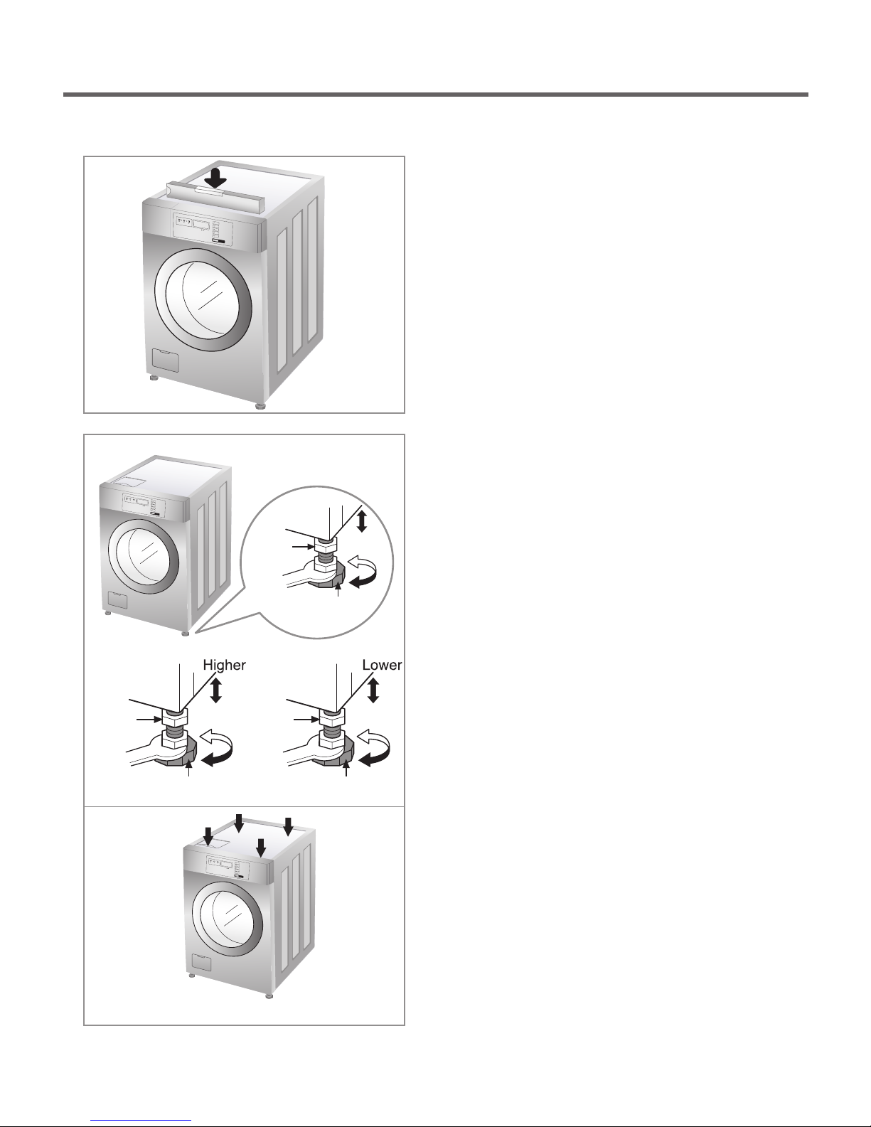
■ Level adjustment
Lock nut
Adjustable feet
Lock nut
Adjustable feet
Lock nut
Adjustable feet
· Leveling the washing machine properly prevents
excessive noise and vibration.
Install the appliance on a solid and level floor
surface, preferably in a corner of the room.
· If the floor is uneven, adjust the adjustable feet as
required. (Do not insert pieces of wood, etc. under
the feet.)
NOTE: Extend the feet no more than necessary to level
the washer. The more the feet are extended, the
more the washer will vibrate.
· Make sure that all four feet are stable and resting on
the floor and then check that the appliance is
perfectly level (Use a level).
· After the washer is level, tighten the lock nuts up
against of the base of the washer. All lock nuts must
be tightened.
· It is critical to adjust the feet perfectly. This must be
done while the washer is spinning with a load. Use
the wrench (supplied) to adjust the feet until there is
no vibration. Then tighten the lock nuts to prevent
further adjustment.
NOTE: If there is vibration and noise during the spin
cycle, re-check the leveling of the washer, adjust
the feet as required, and tighten the lock nuts
securely to prevent changes in adjustment.
Run the washer with a test load to make certain
your washer is properly leveled. Put an
unbalance weight part in the machine.
You can check noise and/or vibration on high
speed spin rpm through the QC test mode
(refer to page 19).
When the machine spins at high speed, verify
that it is stable. If not, adjust the feet
accordingly.
※ Diagonal Check
When pushing down the edges of the washing machine
top plate diagonally, the machine should not move up
and down at all. (Please, check both directions.)
11
Electrical connection
· Do not use an extension cord or double adapter.
· If the supply cord is damaged, it must be replaced by a qualified person in order to avoid a hazard.
· If the machine will not be used for an extended time, unplug it, shut off the water supply and open the door to
provide ventilation.
· Connect the machine to a grounded outlet in accordance with current wiring regulations.
· The appliance must be positioned so that the plug is easily accessible.
WARNING! Concerning the power cord
Most appliances recommend they be placed upon a dedicated circuit; that is, a single outlet circuit which powers only
that appliance and has no additional outlets or branch circuits. Check the specification page of this owner’s manual to be
certain.
Do not overload wall outlets. Overloaded wall outlets, loose or damaged wall outlets, extension cords, frayed power
cords, or damaged or cracked wire insulation are dangerous. Any of these conditions could result in electric shock or fire.
Periodically examine the cord of your appliance, and if its appearance indicates damage or deterioration, unplug it,
discontinue use of the appliance, and have the cord replaced with an exact replacement part by an authorized servicer.
Protect the power cord from physical or mechanical abuse, such as being twisted, kinked, pinched, closed in a door, or
walked upon. Pay particular attention to plugs, wall outlets, and the point where the cord exits the appliance.
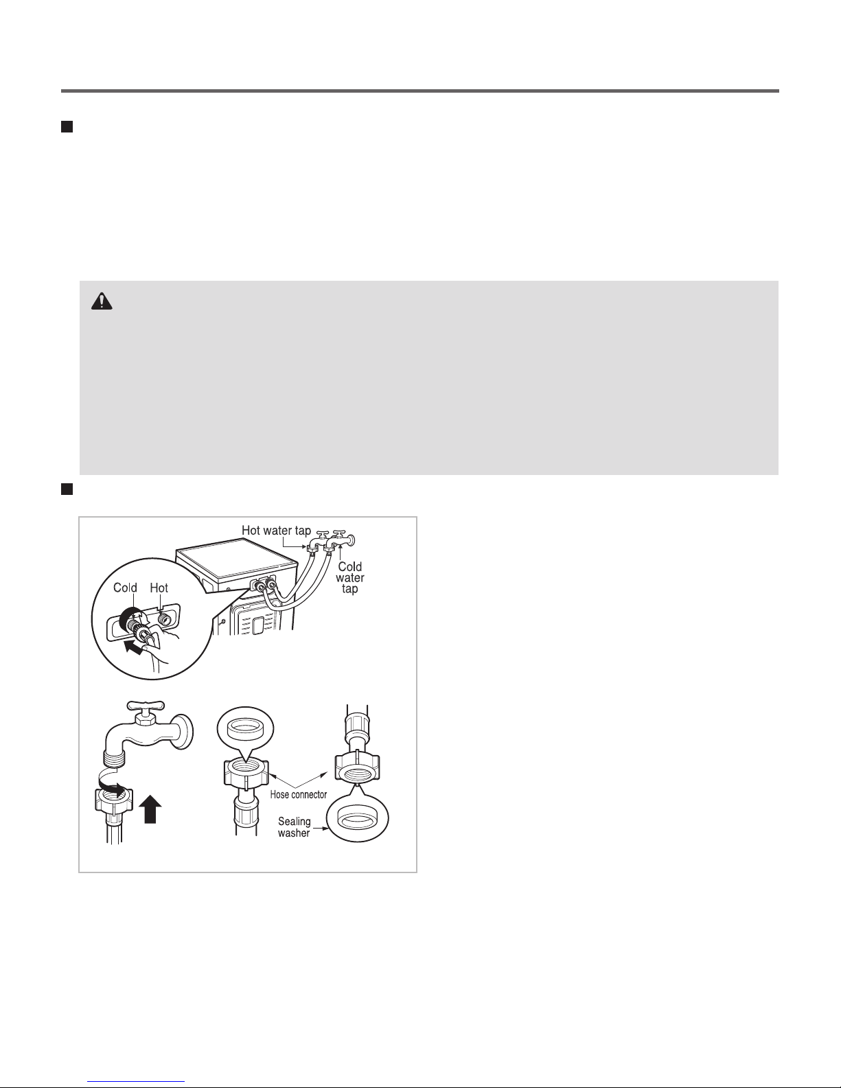
Connecting the water supply hoses
· Water supply pressure must be between
138 ~ 827 kPa (20 - 120psi).
· Do not crossthread when connecting the inlet hose
to the valve.
· If the water supply pressure is more than 120 PSI
a pressure reducing device should be installed.
· Two sealing washers are supplied with the water
inlet hoses to prevent water leaks.
· Check for leakage of washing machine connections
by turning the tap completely on.
· Periodically check the condition of the hose and
replace the hose if necessary.
· Make sure that there is no kink in the hose and that
it is not crushed.
· Be sure that the two water input ports are connected
to the correct water faucets. The connector for hot
water is colored red; the cold is blue.
NOTE: Use new hoses when installing a washing machine. Replace them periodically.
Old hoses should not be used.
Do not install your washing machine in a room where temperatures below freezing may occur.
Frozen hoses may burst under pressure. The reliability of the electronic control unit may be impaired
at temperatures below the freezing point.
If the appliance is delivered in the winter months and temperatures are below freezing,
store the washing machine at room temperature for a few hours before putting it into operation.
12
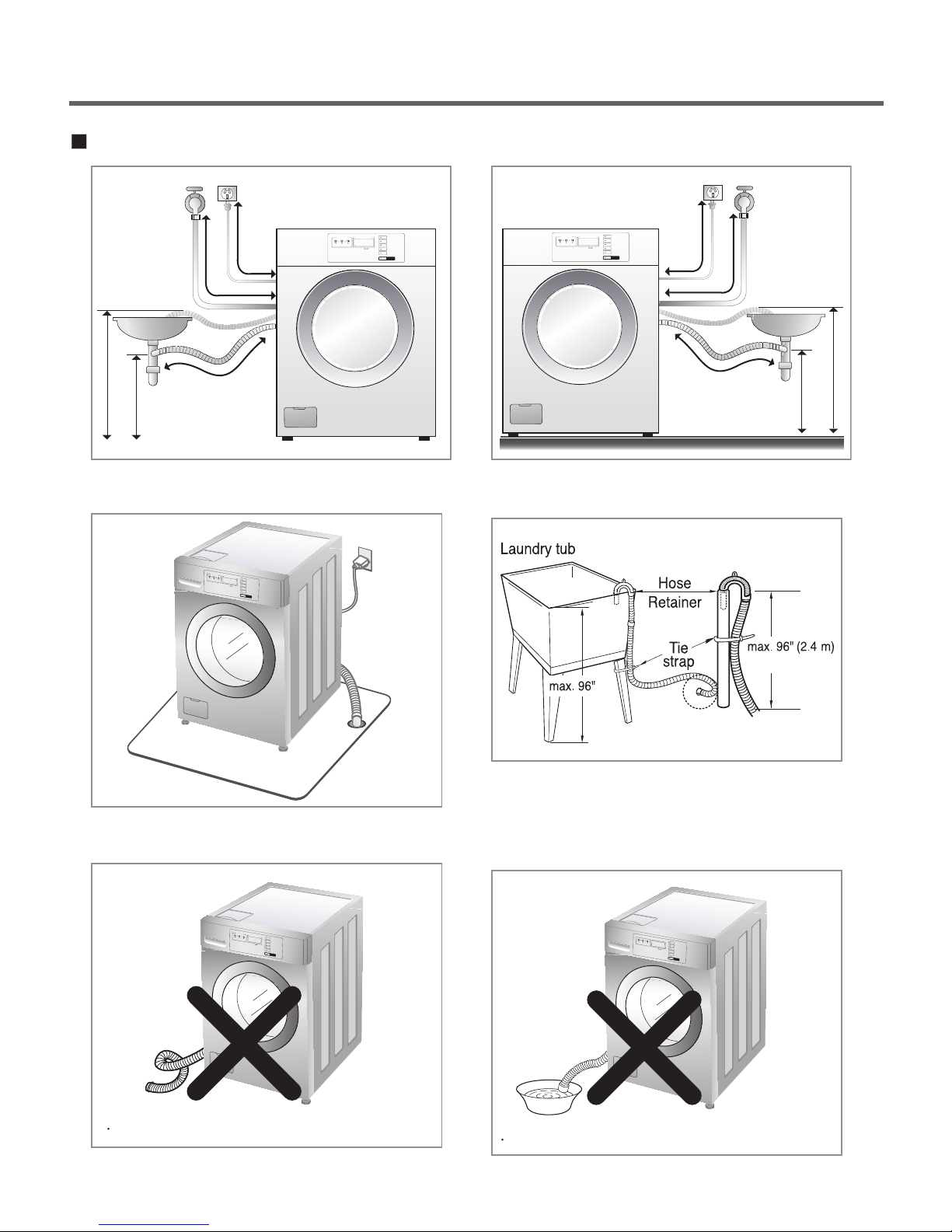
Installation of drain hose
about 78"(2.0m)
about 55"(1.4m)
about 45"(1.1m)
about 70"(1.8m)
max 39"(1.0m)
min 24"(0.6m)
• When installing the drain hose at a sink, secure it so it
cannot break away and cause flooding and damage.
about 45"(1.1m)
about 70"(1.8m)
min 24"(0.6m)
• Properly securing the drain hose will protect the
floor from damage due to water leakage.
max 39"(1.0m)
• Place the end of the drain hose in the hole of the
floor drain system.
Make sure that the hose is not twisted.
• The drain hose should not be placed higher than
96 in. from the bottom of the washer.
• Properly securing the drain hose will protect the floor
from damage due to water leakage.
Do not submerge the end of the hose.
13
1 25
4 3
1 25
4
3
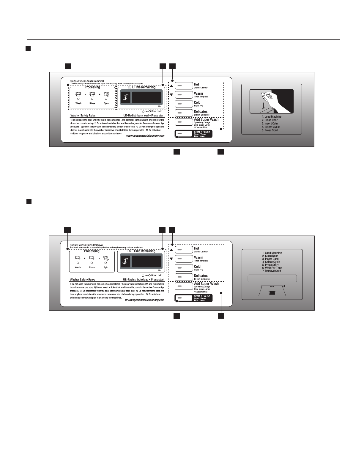
6. OPERATION
COIN TYPE
- SIDE BY SIDE (TCW2013QS1)
CARD TYPE
- SIDE BY SIDE (TCW2013CS1)
OPTIONAL FUNCTION BUTTON
1. DISPLAY LED 4. START/PAUSE BUTTON
2. CYCLE BUTTON 5. STATUS LED
3. OPTIONAL CYCLE BUTTON
OPTIONAL FUNCTION BUTTON
14
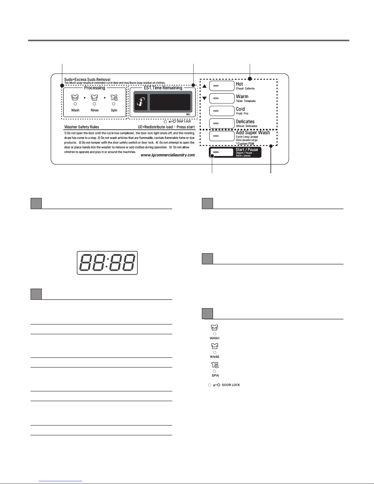
Start/Pause button
Display LEDStatus LED Cycle button
Optional function button
1
DISPLAY LED
3
OPTIONAL FUNCTION BUTTON
The display shows the vend price and remaining time
and programming options. Error codes are also
displayed here.
2
CYCLE BUTTON
Press the CYCLE button to select the desired cycle
based on laundry types and conditions.
Hot
Use for hot washing for heavy fabrics, such as white
clothes, table linens, and heavily soiled clothes.
Warm
Use for warm washing for heavy fabrics, such as
jeans, corduroys, or work clothes.
Cold
Wash time or rinse cycle can be added when
additional coin is inserted or a valid cash card is
entered.
4
START/PAUSE BUTTON
The START/PAUSE LED flashes when the full
vend price has been satisfied and the cycle has been
chosen.
5
STATUS LED
· LED flashes whenever the washing
· LED flashes whenever the Rinsing
· LED flashes whenever the Spining
· LED flashes whenever the door lock
cycle is in operation.
cycle is in operation.
cycle is in operation.
is activated.
Use for Cold washing for sturdy fabrics, such as
work casual work.
Delicates
Use for cold washing for synthetic fabrics, such as
washable knit fabric and no-iron finishes.
15
 Loading...