

LG SJ122CD, SJ182CD Owner's Manual

ENGLISH
LG
Room Air Conditioner
INSTALLATION MANUAL
LG
website http://www.lgservice.com
IMPORTANT
• Please read this instruction manual completely before
installing the product.
• When the power cord is damaged, replacement should be
performed by authorized personnel only.
• Installation work must be performed in accordance with
the national wiring standards by authorized personnel
only.
• Please retain this installation manual for future reference
after reading it thoroughly.
ESPAÑOL

2 Room Air Conditioner
Room Air Conditioner Installation Manual
TABLE OF CONTENTS
Safety Precautions............................3
Introduction........................................6
Symbols used in this manual..........6
Features...........................................6
Installation..........................................7
Installation parts...............................7
Installation tools...............................7
Installation map................................8
Selecting the best location .............9
Piping length and elevation...........10
Fixing installation plate..................11
Drilling a hole in the wall...............11
Flaring work...................................12
Connecting the piping ..................13
Connecting the cables ..................19
Checking the drainage..................21
Forming the piping.........................22
Air purging......................................23
Test running ...................................25
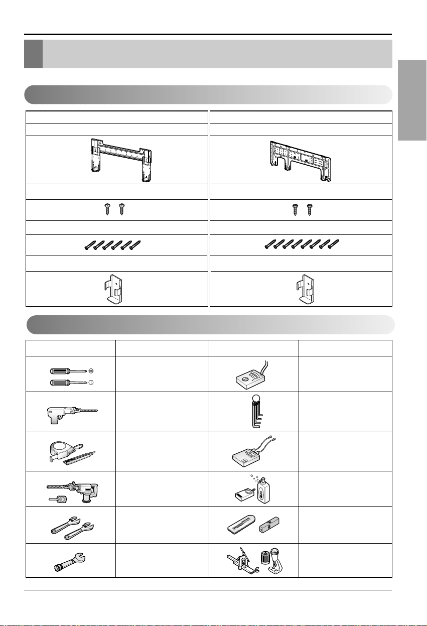
❏ Four type "A" screws & plastic
anchors
❏ Connecting cable
❏ Installation guide map
❏ Pipes: Gas side
Liquid side
❏ Insulation materials
❏ Additional drain pipe
(Outer diameter ..............15.5mm)
❏ Two type "B" screws
❏ Level gauge
❏ Screw driver
❏ Electric drill
❏ Hole core drill(ø70mm)
❏ Horizontal meter
❏ Flaring tool set
❏ Specified torque wrenches
1.8kg.m, 4.2kg.m, 5.5kg.m,
6.6kg.m
(different depending on model No.)
❏ Spanner........................Half union
❏ A glass of water
❏ Screw driver
❏ Hexagonal wrench(4mm)
❏ Gas-leak detector
❏ Vacuum pump
❏ Gauge manifold
❏ Owner's manual
❏ Thermometer
❏ Remote control holder
Installation
Requirements
Required Parts Required T ools
Installation Manual 3
ENGLISH
Safety Precautions
To prevent the injury of the user or other people and proper ty damage, the following instructions
must be followed.
■ Be sure to read before installing the air conditioner.
■ Be sure to obser ve the cautions specified here as they include important items related to safety.
■ Incorrect operation due to ignoring instruction will cause har m or damage. The seriousness is
classified by the following indications.
■ The meanings of the symbols used in this manual are as shown below.
This symbol indicates the possibility of death or serious injury.
This symbol indicates the possibility of injury or damage to properties only.
■ Installation
Be sure not to do.
Be sure to follow the instruction.
Safety Precautions
Always perform grounding.
• Otherwise, it may cause
electrical shock.
Don’t use a power cord, a
plug or a loose socket
which is damaged.
• Otherwise, it may cause a fire
or electrical shock.
For installation of the product,
always contact the service
center or a professional
installation agency.
• Otherwise, it may cause a fire,
electrical shock, explosion or
injury.
Securely attach the
electrical part cover to the
indoor unit and the service
panel to the outdoor unit.
• If the electrical part cover of
the indoor unit and the service
panel of the outdoor unit are
not attached securely, it could
result in a fire or electric
shock due to dust, water, etc.
Always install an air leakage
breaker and a dedicated
switching board.
• No installation may cause a
fire and electrical shock.
Do not keep or use
flammable gases or
combustibles near the air
conditioner.
• Otherwise, it may cause a fire
or the failure of product.
Ensure that an installation frame of the
outdoor unit is not damaged due to use for
a long time.
• It may cause injury or an accident.
Do not disassemble or repair the product
randomly.
• It will cause a fire or electrical shock.

4 Room Air Conditioner
Safety Precautions
Do not install the product at a place that
ther is concern of falling down.
• Otherwise, it may result in personal injury.
Use caution when unpacking and installing.
• Sharp edges may cause injury.
Take the power plug out if
necessary,holding the head
of the plug and do not touch
it with wet hands.
• Otherwise, it may cause a fire
or electrical shock.
Do not use the power cord
near the heating tools.
• Otherwise, it may cause a fire
and electrical shock.
Do not open the suction
inlet of the indoor/outdoor
unit during operation.
• Otherwise, it may electrical
shock and failure.
Do not allow water to run
into electrical parts.
• Otherwise, it may cause the
failure of machine or electrical
shock.
Hold the plug by the head
when taking it out.
• It may cause electric shock
and damage.
Never touch the metal parts
of the unit when removing
the filter.
• They are sharp and may
cause injury.
Do not share the outlet with
other appliances.
• It will cause an electric shock
or a fire due to heat
generation.
Do not use the damaged
power cord.
• Otherwise, it may cause a fire
or electrical shock.
Do not modify or extend the
power cord randomly.
• Otherwise, it may cause a fire
or electrical shock.
Take care so that the power
cord may not be pulled
during operation.
• Otherwise, it may cause a fire
or electrical shock.
Unplug the unit if strange
sounds, smell, or smoke
comes from it.
• Otherwise, it may cause
electrical shock or a fire.
Keep the flames away.
• Otherwise, it may cause a fire.
Do not step on the indoor/outdoor unit and
do not put anything on it.
• It may cause an injury through dropping of the
unit or falling down.
Do not place a heavy object on the power
cord.
• Otherwise, it may cause a fire or electrical
shock.
When the product is submerged into water,
always contact the service center.
• Otherwise, it may cause a fire or electrical
shock.
Take care so that children may not step on
the outdoor unit.
• Otherwise, children may be seriously injured
due to falling down.
■ Operation
Installation Manual 5
ENGLISH
Safety Precautions
■ Installation
Install the drain hose to ensure that drain
can be securely done.
• Otherwise, it may cause water leakage.
Install the product so that the noise or hot
wind from the outdoor unit may not cause
any damage to the neighbors.
• Otherwise, it may cause dispute with the
neighbors.
Always inspect gas leakage after the
installation and repair of product.
• Otherwise, it may cause the failure of product.
Keep level parallel in installing the product.
• Otherwise, it may cause vibration or water
leakage.
Avoid excessive cooling and perform
ventilation sometimes.
• Otherwise, it may do harm to your health.
Use a soft cloth to clean. Do not use wax,
thinner, or a strong detergent.
• The appearance of the air conditioner may
deteriorate, change color, or develop surface
flaws.
Do not use an appliance for special purposes
such as preserving animals vegetables,
precision machine, or art articles.
• Otherwise, it may damage your properties.
Do not place obstacles around the flow inlet
or outlet.
• Otherwise, it may cause the failure of appliance
or an accident.
■ Operation
6 Room Air Conditioner
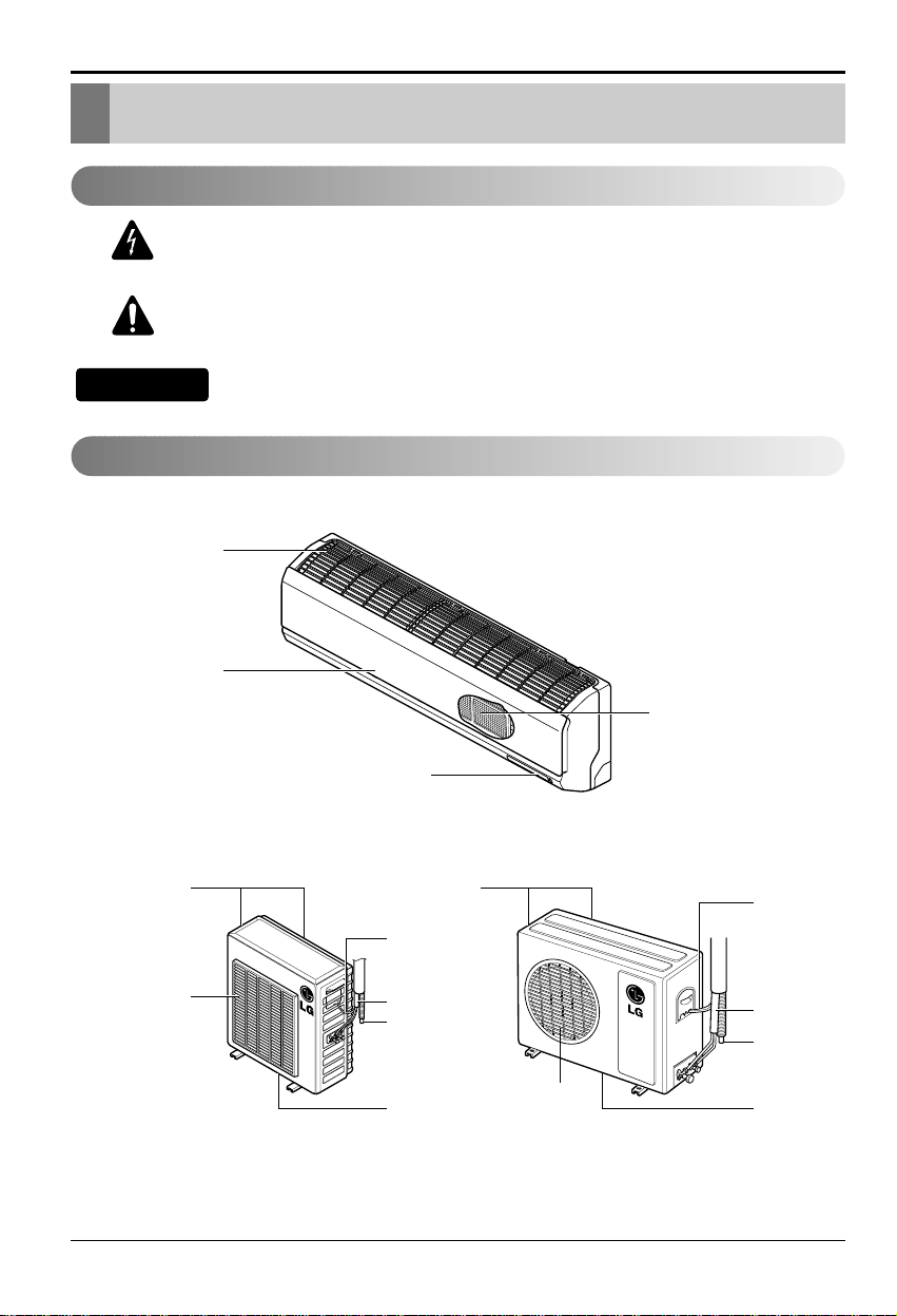
Introduction
This symbol alerts you to the risk of electric shock.
This symbol alerts you to hazards that may cause harm to
the air conditioner.
This symbol indicates special notes.
NOTICE
Introduction
Symbols used in this Manual
Features
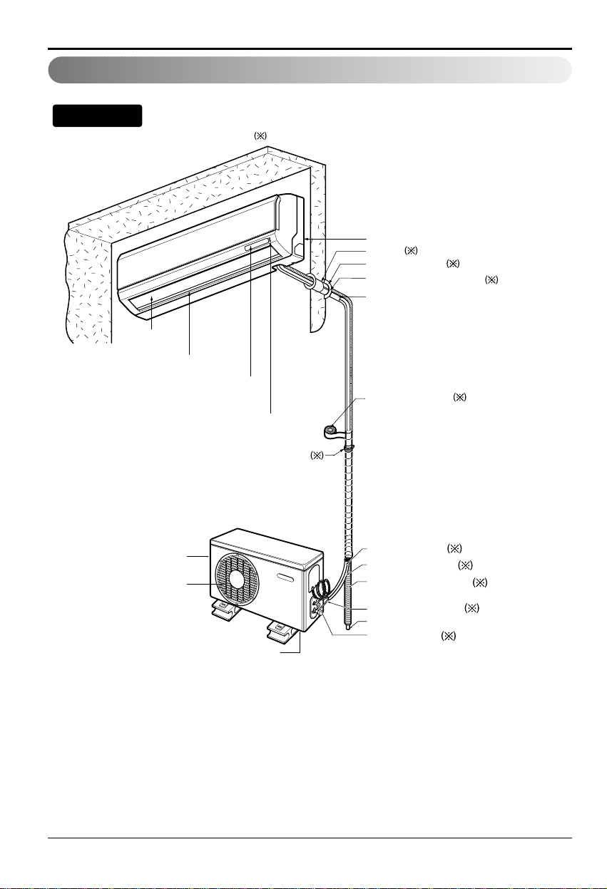
Air Intake Vents
Air Outlet Vents
Air Intake Vents
Air Outlet Vents
Connecting
Wires
Connecting
Wires
Piping
Piping
Drain Hose
Drain Hose
Base Plate
Base Plate
Air Inlet
Air Filter
Front Panel
Signal Receptor
Installation Manual 7
ENGLISH
Installation
Type "A" screw (6 EA) Type "A" screw (8 EA)
Type "B" screw Type "B" screw
Remote control holderRemote control holder
Type 1 Type 2
Installation plate Installation plate
Figure FigureName
Screw driver
Electric drill
Measuring tape, Knife
Hole core drill
Spanner
Torque wrench
Ohmmeter
Hexagonal wrench
Ammeter
Gas-leak detector
Thermometer,
Horizontal meter
Flaring tool set
Name
Installation Parts
Installation T ools
Installation
Read carefully, and then follow step by step.
8 Room Air Conditioner
Installation
Installation Map
Installation parts you should purchase.
Vertical Air deflector
Air Discarge
Forced Operation Button
Operation Indication Lamps/
Signal Receptor
Vinyl tape (Wide)
• Apply after carrying out a
drainage test.
• To carry out the drainage
test, remove the air filters
and pour water into the heat
exchanger.
Saddle
Gas side piping (Optional Parts)
Liquid side piping (Optional Parts)
Additional drain pipe
Vinyl tape (Narrow)
Drain Hose
Base Plate
Air Outlet Vents
Air Inlet Vents
Connecting cable
(Optional Parts)
Installation plate
Sleeve
Bushing-Sleeve
Putty(Gum Type Sealer)
Bend the pipe as closely
on the wall as possible,
but be careful that it
doesn't break.
NOTICE
Installation Manual 9
ENGLISH
Installation
Indoor unit
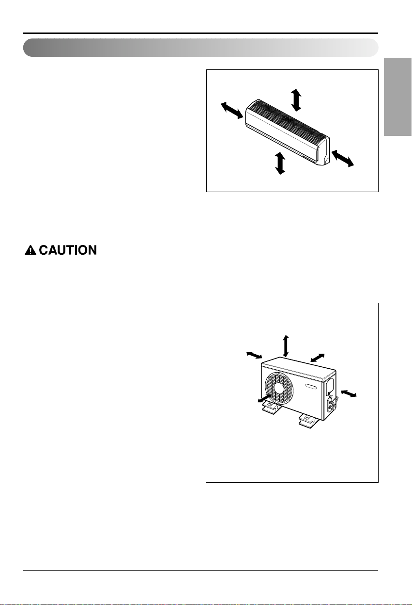
1. Do not have any heat or steam near the unit.
2. Select a place where there are no obstacles
in front of the unit.
3. Make sure that condensation drainage can be
conveniently routed away.
4. Do not install near a doorway.
5. Ensure that the interval between a wall and
the left (or right) of the unit is more than
10cm.The unit should be installed as high as
possible on the wall, allowing a minimum of
20cm from ceiling.
6. Use a stud finder to locate studs to prevent
unnecessary damage to the wall.
Outdoor unit
1. If an awning is built over the unit to prevent
direct sunlight or rain exposure, make sure
that heat radiation from the condenser is not
restricted.
2. Ensure that the space around the back and
sides is more than 30cm.The front of the unit
should have more than 70cm of space.
3. Do not place animals and plants in the path
of the warm air.
4.Take the weight of the air conditioner into
account and select a place where noise and
vibration are minimum.
5. Select a place where the warm air and noise
from the air conditioner do not disturb
neighbors.
Select the best Location
More than 20cm
More than
10cm
More than 2.3m
More than
10cm
Install the indoor unit on the wall where the height from the floor is more than 2.3 meters.
More than 30cm More than 30cm
More
than 60cm
More than 60cm
More than 70cm
10 Room Air Conditioner
Installation
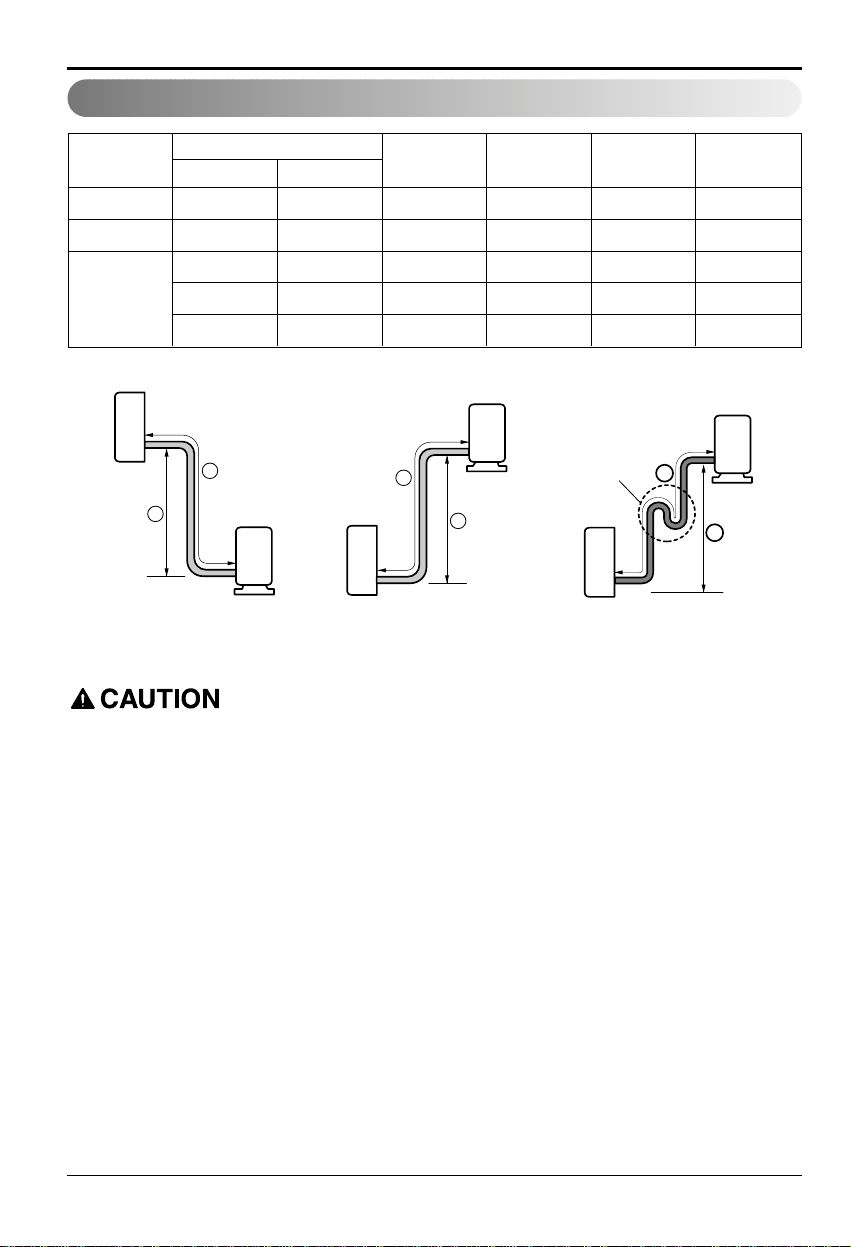
Piping Length and Elevation
7k, 8k, 9k 3/8" 1/4" 7.5 7 15 20
11k, 12k, 14k 1/2" 1/4" 7.5 7 15 20
1/2" 1/4" 7.5 15 30 20
18k, 24k, 26k 5/8" 1/4" 7.5 15 30 20
5/8" 3/8" 7.5 15 30 30
Pipe Size
Capacity
(Btu/h)
GAS LIQUID
Max.
Length A (m)
Additional
Refrigerant (g/m)
Max.
Elevation B (m)
Standard
Length (m)
Outdoor unit
Indoor unit
A
B
Outdoor unit
Indoor unit
A
B
A
Oil trap
Outdoor unit
Indoor unit
B
If piping length is more than 5m
Capacity is based on standard length and maximum allowance length is on the basis of reliability.
Oil trap should be installed every 5~7 meters.
Installation Manual 11
ENGLISH
Installation
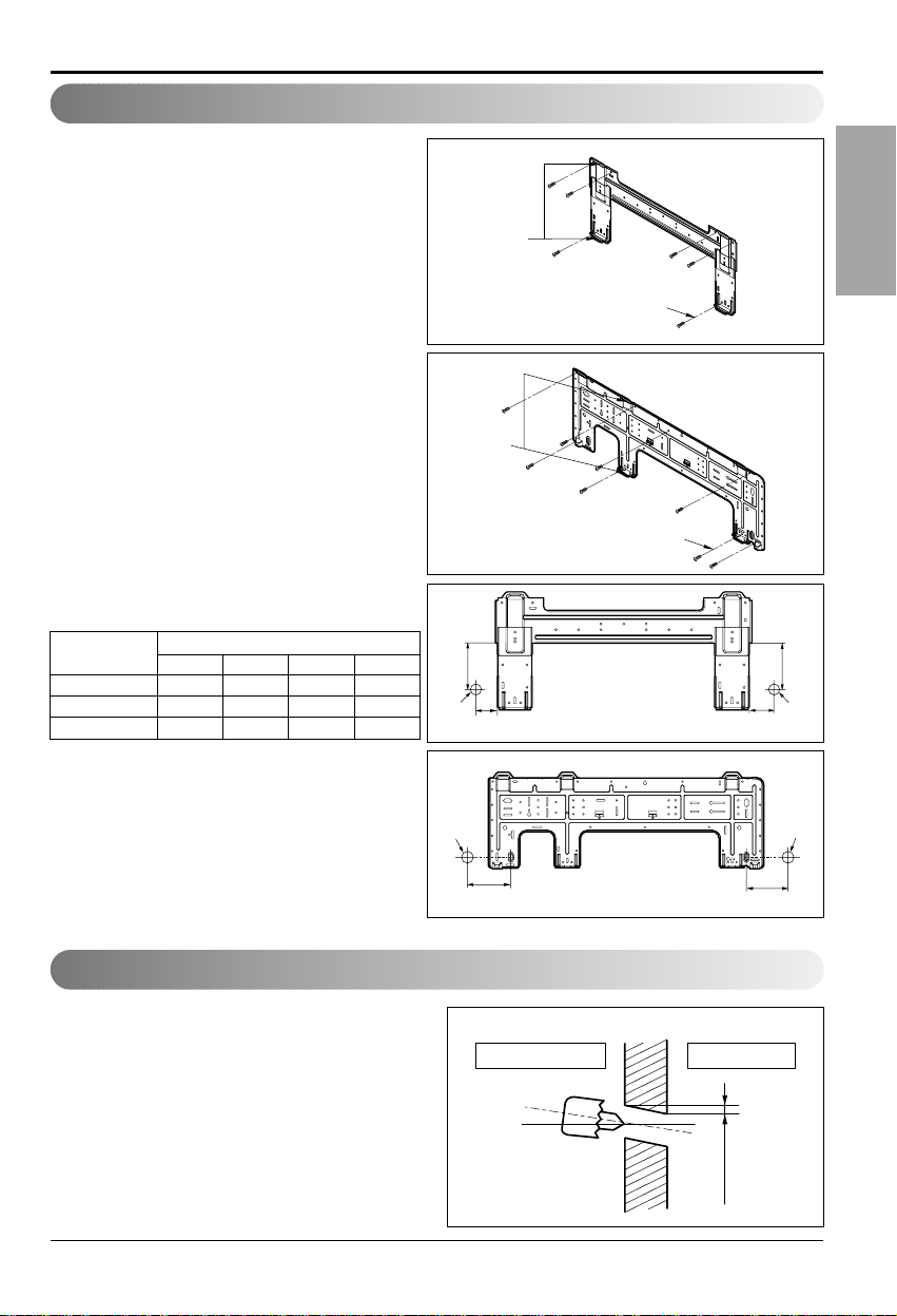
Fixing Installation Plate
• Drill the piping hole with a ø70mm hole core
drill. Drill the piping hole at either the right or
the left with the hole slightly slanted to the
outdoor side.
Drill a Hole in the Wall
5-7mm
(3/16"~5/16")
Indoor
WALL
Outdoor
The wall you select should be strong and
solid enough to prevent vibration
1. Mount the installation plate on the wall with
type "A" screws.If mounting the unit on a
concrete wall, use anchor bolts.
• Mount the installation plate horizontally by
aligning the centerline using a level.
2. Measure the wall and mark the centerline.
It is also important to use caution
concerning the location of the installation
plate-routing of the wiring to power outlets
is through the walls typically. Drilling the
hole through the wall for piping
connections must be done safely.
Chassis
Hook
Installation Plate
Type “A”
ABCD
S4 55 105 65 105
SE 70 110 90 110
S5/S8 100 122 240 122
CHASSIS
(Grade)
Distance (mm)
<Type 1>
<Type 1>
<Type 1>
Installation plate
Left rear piping Right rear piping
Ø70mm
133mm
Ø70mm
100mm
<Type 2>
Chassis
Hook
Installation Plate
Type “A”
<Type 2>
D
C
Ø70mm
Left rear piping Right rear piping
Installation plate
A
B
Ø70mm
12 Room Air Conditioner
Installation
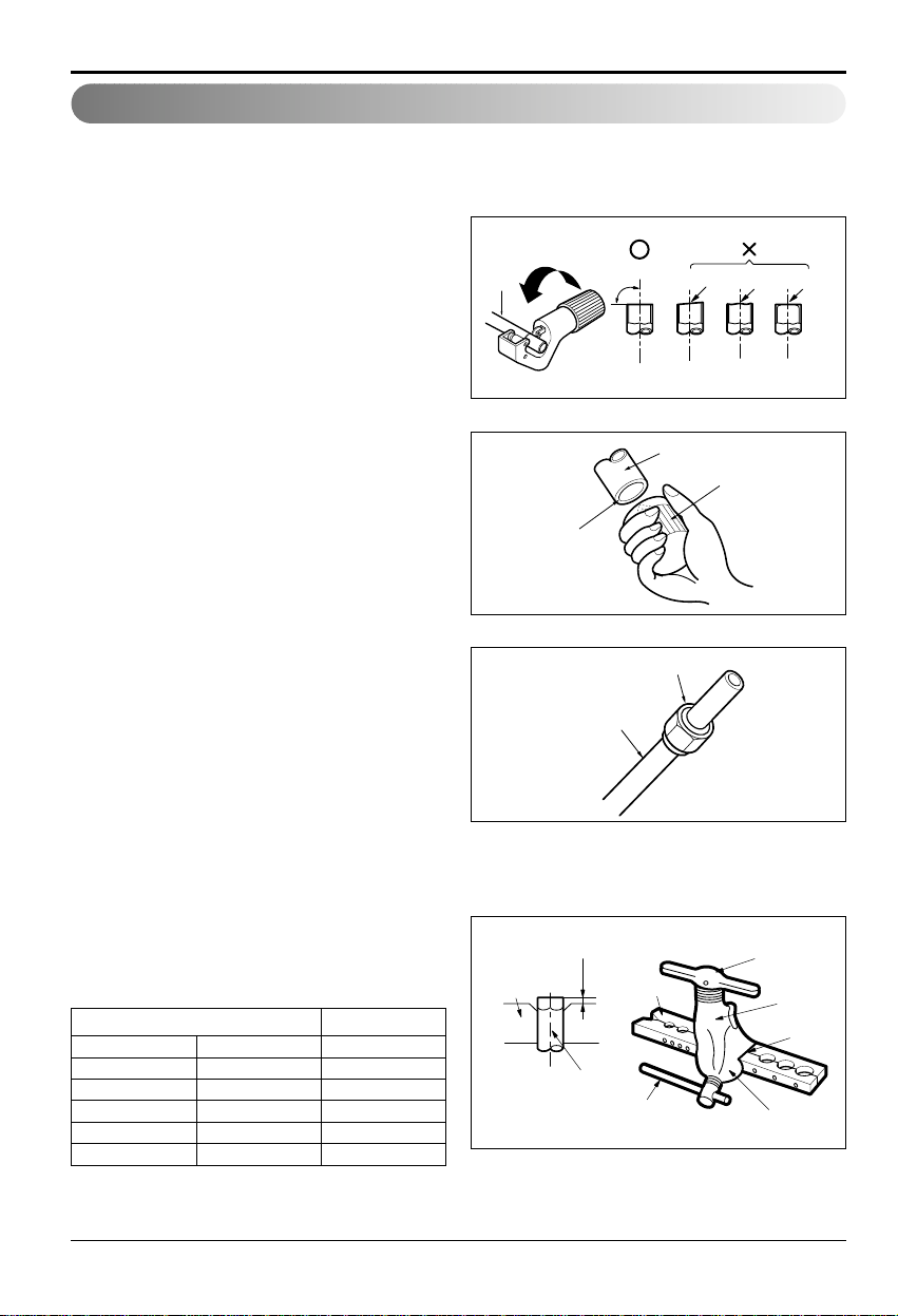
Flaring W ork
Main cause for gas leakage is due to defect in flaring work.Carr y out correct flaring wor k in the
following procedure.
Cut the pipes and the cable.
1. Use the piping kit accessory or the pipes
purchased locally.
2. Measure the distance between the indoor and
the outdoor unit.
3. Cut the pipes a little longer than measured
distance.
4. Cut the cable 1.5m longer than the pipe length.
Burrs removal
1. Completely remove all burrs from the cut cross
section of pipe/tube.
2. Put the end of the copper tube/pipe in a
downward direction as you remove burrs in
order to avoid dropping burrs into the tubing.
Putting nut on
• Remove flare nuts attached to indoor and
outdoor unit, then put them on pipe/tube having
completed burr removal.
(not possible to put them on after flaring work)
Flaring work
1. Firmly hold copper pipe in a die in the dimension
shown in the table below.
2. Carry out flaring work with the flaring tool.
Copper
pipe
90°
Slanted Uneven Rough
mm inch mm
Ø6.35 1/4" 1.1~1.3
Ø9.52 3/8" 1.5~1.7
Ø12.7 1/2" 1.6~1.8
Ø15.88 5/8" 1.6~1.8
Ø19.05 3/4" 1.9~2.1
Outside diameter A
Bar
Point down
Copper tube
"A"
Copper pipe
Clamp handle
Pipe
Reamer
Flare nut
Handle
Bar
Yoke
Cone
Red arrow mark
Installation Manual 13
ENGLISH
Installation
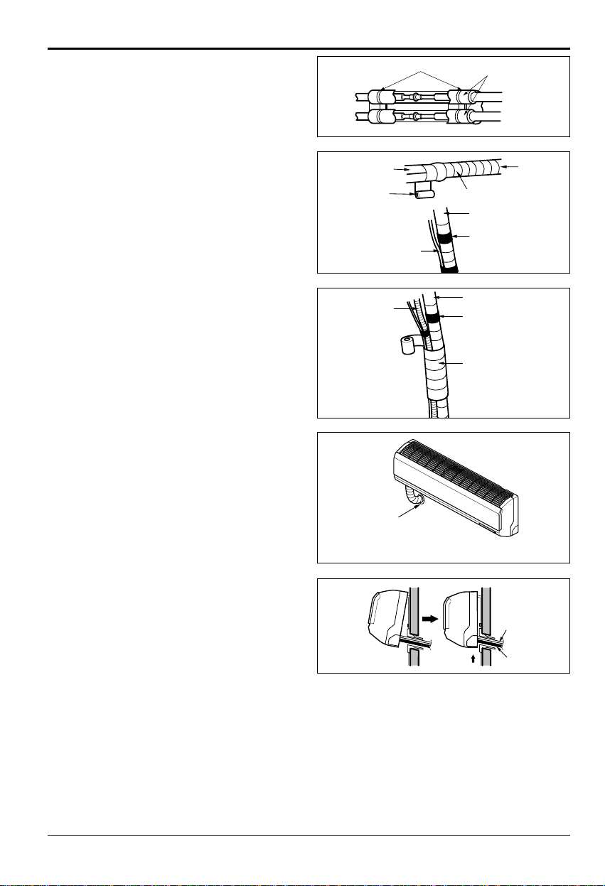
Check
1. Compare the flared work with the figure by.
2. If a flared section is defective, cut it off and
do flaring work again.
Indoor
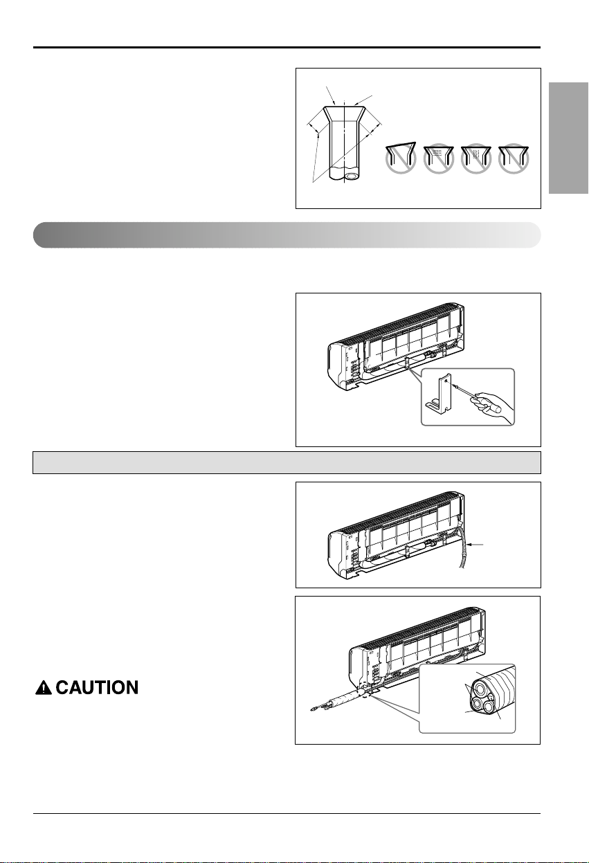
1. Prepare the indoor unit's piping and drain hose for installation through the wall.
2. Remove the plastic tubing retainer(see the
illustration by) and pull the tubing and drain
hose away from chassis.
3. Replace only the plastic tubing holder 1, not
the holder 2 in the original position.
1. Route the indoor tubing and the drain hose in
the direction of rear right.
2.
Insert the connecting cable into the indoor unit
from the outdoor unit through the piping hole.
• Do not connect the cable to the indoor unit.
• Make a small loop with the cable for easy
connection later.
3.Tape the tubing, drain hose, and the
connecting cable.Be sure that the drain hose
is located at the lowest side of the bundle.
Locating at the uper side can cause drain pan
to overflow inside the unit.
If the drain hose is routed inside the room,
insulate the hose with an insulation material*
so that dripping from "sweating"(condensation)
will not damage furniture or floors.
*Foamed polyethylene or equivalent is
recommended.
Inclined
Inside is shiny without scratches
Smooth all round
Even length
all round
Surface
damaged
Cracked Uneven
thickness
= Improper flaring =
Connecting the Piping
For right rear piping
Drain hose
Tape
Connecting
pipe
Drain hose
Connecting cable
14 Room Air Conditioner
Installation
4. Indoor unit installation
Hook the indoor unit onto the upper portion of
the installation plate.(Engage the two hooks
of the rear top of the indoor unit with the
upper edge of the installation plate.) Ensure
that the hooks are properly seated on the
installation plate by moving it left and right.
Press the lower left and right sides of the unit
against the installation plate until the hooks
engage into their slots(clicking sound).
Connecting the piping to the indoor unit and
drain hose to drain pipe.
1. Align the center of the pipes and sufficiently
tighten the flare nut by hand.
2.Tighten the flare nut with a wrench.
3.When extending the drain hose at the indoor
unit, install the drain pipe.
Wrap the insulation material around the
connecting portion.
1. Overlap the connection pipe insulation
material and the indoor unit pipe insulation
material. Bind them together with vinyl tape
so that there may be no gap.
2.Wrap the area which accommodates the rear
piping housing section with vinyl tape.
3. Bundle the piping and drain hose together by
wrapping them with vinyl tape for enough to
cover where they fit into the rear piping
housing section.
Drain hose
Connecting
cable
mm inch kgf.m
Ø6.35 1/4" 1.8~2.5
Ø9.52 3/8" 3.4~4.2
Ø12.7 1/2" 5.5~6.6
Ø15.88 5/8" 6.3~8.2
Outside diameter Torque
Indoor unit tubing Flare nut Pipes
Open-end wrench (fixed)
Flare nut
Wrench
Indoor unit tubing
Drain pipe
Connection pipe
Connection pipe
Vinyl tape (wide)
Connecting cable
Pipe
Drain hose
Indoor unit drain hose
Vinyl tape(narrow)
Adhesive
Plastic bands
Vinyl tape(narrow)
Wrap with vinyl tape
Insulation material
Wrap with vinyl tape
Vinyl tape(wide)
Indoor unit pipe
Pipe
Installation Manual 15
ENGLISH
Installation
1. Route the indoor tubing and the drain hose to
the required piping hole position.
2. Insert the piping, drain hose, and the
connecting cable into the piping hole.
3.
Insert the connecting cable into the indoor unit.
• Don't connect the cable to the indoor unit.
• Make a small loop with the cable for easy
connection later.
4.Tape the drain hose and the connecting
cables.
5. Indoor unit installation
• Hang the indoor unit from the hooks at the
top of the installation plate.
• Insert the spacer etc. between the indoor
unit and the installation plate and separate
the bottom of the indoor unit from the wall.
Connecting the piping to the indoor unit and
the drain hose to drain pipe.
1. Align the center of the pipes and sufficiently
tighten the flare nut by hand.
2.Tighten the flare nut with a wrench.
3.When extending the drain hose at the indoor
unit, install the drain pipe.
For left rear piping
mm inch kgf.m
Ø6.35 1/4" 1.8~2.5
Ø9.52 3/8" 3.4~4.2
Ø12.7 1/2" 5.5~6.6
Ø15.88 5/8" 6.3~8.2
Outside diameter Torque
1 2
Indoor unit
Installation plate
8cm
Spacer
Connecting
cable
Drain pipe
Indoor unit tubing Flare nut Pipes
Open-end wrench (fixed)
Flare nut
Wrench
Indoor unit tubing
Drain hose
Indoor unit drain hose
Vinyl tape
Adhesive
Connection pipe
(narrow)
16 Room Air Conditioner
Installation
Wrap the insulation material around the
connecting portion.
1. Overlap the connection pipe heat insulation
and the indoor unit pipe heat insulation
material. Bind them together with vinyl tape
so that there may be no gap.
2.Wrap the area which accommodates the rear
piping housing section with vinyl tape.
3. Bundle the piping and drain hose together by
wrapping them with cloth tape over the range
within which they fit into the rear piping
housing section.
Reroute the pipings and the drain hose
across the back of the chassis.
Indoor unit installation
1. Remove the spacer.
2. Ensure that the hooks are properly seated on
the installation plate by moving it left and
right.
3. Press the lower left and right sides of the unit
against the installation plate until the hooks
engage into their slots(clicking sound).
Plastic bands
Insulation material
Connection
pipe
Vinyl tape
(wide)
Connecting cable
Wrap with vinyl tape
Pipe
Vinyl tape(narrow)
Indoor
unit piping
Drain hose
Piping for
passage through
piping hole
Pipe
Vinyl tape(narrow)
Wrap with
vinyl tape(wide)
Connecting
cable
Drain hose
Installation Manual 17
ENGLISH
Installation
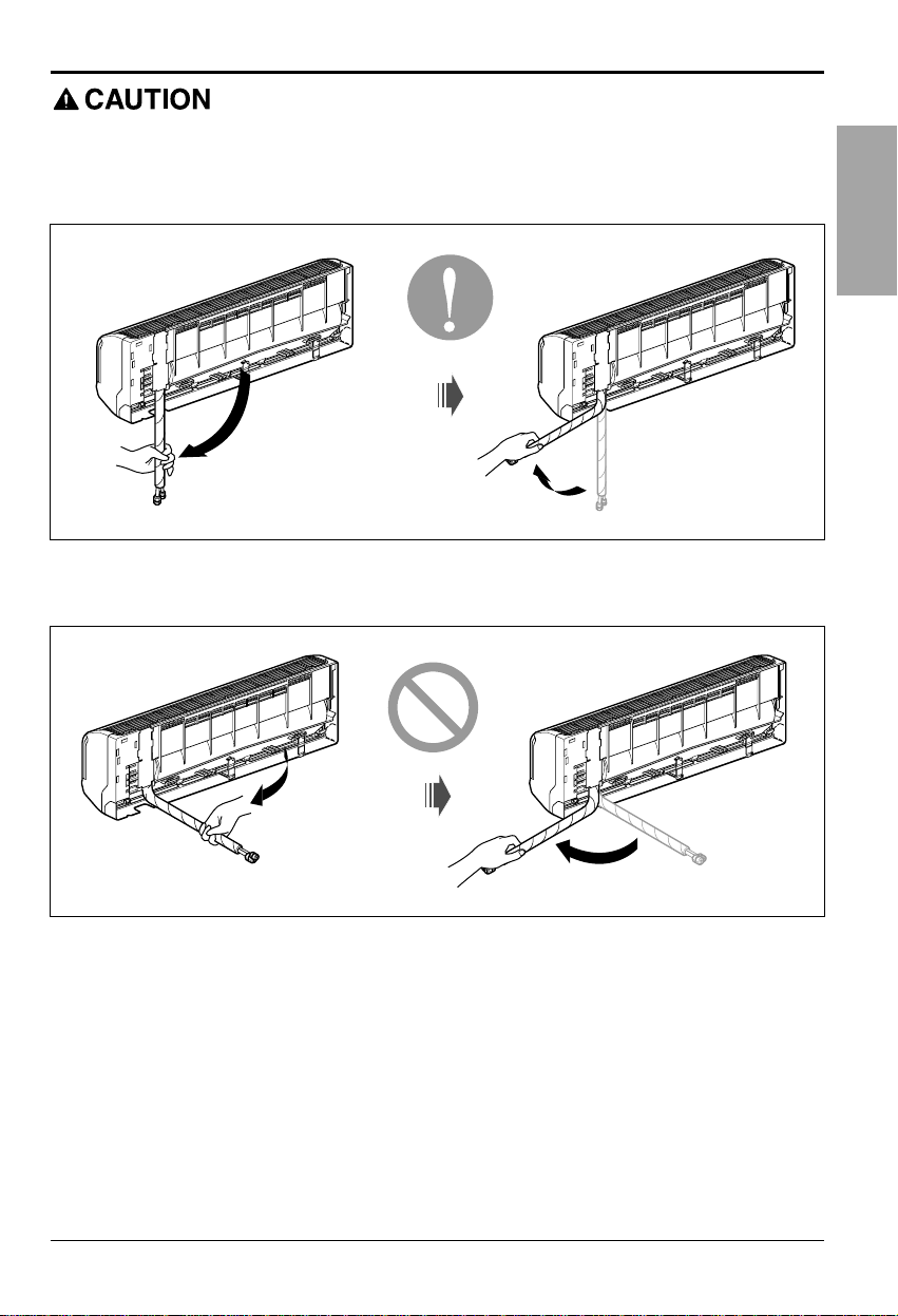
Installation Information. For left piping.Follow the instruction below.
Good case
• Press on the upper side of clamp and unfold the tubing to downward slowly.
Bad case
• Following bending type from right to left may cause damage to the tubing.
 Loading...