

LG RE29FB51RQ, RL-29FB51RQ Service Manual
COLOR TV
SERVICE MANUAL
CAUTION
BEFORE SERVICING THE CHASSIS,
READ THE SAFETY PRECAUTIONS IN THIS MANUAL.
CHASSIS : MC-036A
MODEL:RE/RL-29FB51RQ
website:http://biz.LGservice.com
e-mail:http://www.LGEservice.com/techsup.html
Jul.,2003
Printed in KoreaP/NO : 3828VD0151B

- 2 -
CONTENTS
CONTENTS .............................................................................................. 2
SAFETY PRECAUTIONS .........................................................................3
SERVICING PRECAUTIONS ................................................................... 4
SPECIFICATION ...................................................................................... 6
ADJUSTMENT INSTRUCTION .................................................................8
TROUBLE SHOOTING............................................................................16
BLOCK DIAGRAM...................................................................................20
PRINTED CIRCUIT BOARD....................................................................22
EXPLODED VIEW .................................................................................. 28
EXPLODED VIEW PARTS LIST..............................................................29
REPLACEMENT PARTS LIST ............................................................... 30
SVC. Sheet .................................................................................................
- 3 -
SAFETY PRECAUTIONS
Many electrical and mechanical parts in this chassis have special safety-related characteristics. These parts are identified by in
the Schematic Diagram and Replacement Parts List.
It is essential that these special safety parts should be replaced with the same components as recommended in this manual to
prevent X-RADIATION, Shock, Fire, or other Hazards.
Do not modify the original design without permission of manufacturer.
General Guidance
An isolation Transformer should always be used during
the servicing of a receiver whose chassis is not isolated from
the AC power line. Use a transformer of adequate power rating
as this protects the technician from accidents resulting in
personal injury from electrical shocks.
It will also protect the receiver and it's components from being
damaged by accidental shorts of the circuitry that may be
inadvertently introduced during the service operation.
If any fuse (or Fusible Resistor) in this TV receiver is blown,
replace it with the specified.
When replacing a high wattage resistor (Oxide Metal Film
Resistor, over 1W), keep the resistor 10mm away from PCB.
Keep wires away from high voltage or high temperature parts.
Due to high vacuum and large surface area of picture tube,
extreme care should be used in handling the Picture Tube.
Do not lift the Picture tube by it's Neck.
X-RAY Radiation
Warning:
To determine the presence of high voltage, use an accurate
high impedance HV meter.
Adjust brightness, color, contrast controls to minimum.
Measure the high voltage.
The meter reading should indicate
23.5
!1.5KV: 14-19 inch, 26!1.5KV: 19-21 inch,
29.0
!1.5KV: 25-29 inch, 30.0 ! 1.5KV: 32 inch
If the meter indication is out of tolerance, immediate service
and correction is required to prevent the possibility of
premature component failure.
Before returning the receiver to the customer,
always perform an AC leakage current check on the exposed
metallic parts of the cabinet, such as antennas, terminals, etc.,
to be sure the set is safe to operate without damage of
electrical shock.
Leakage Current Cold Check(Antenna Cold Check)
With the instrument AC plug removed from AC source,
connect an electrical jumper across the two AC plug prongs.
Place the AC switch in the on position, connect one lead of
ohm-meter to the AC plug prongs tied together and touch other
ohm-meter lead in turn to each exposed metallic parts such as
antenna terminals, phone jacks, etc.
If the exposed metallic part has a return path to the chassis, the
measured resistance should be between 1MΩ and 5.2MΩ.
When the exposed metal has no return path to the chassis the
reading must be infinite.
An other abnormality exists that must be corrected before the
receiver is returned to the customer.
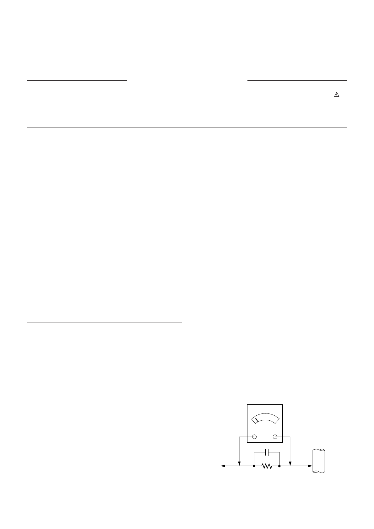
Leakage Current Hot Check (See below Figure)
Plug the AC cord directly into the AC outlet.
Do not use a line Isolation Transformer during this check.
Connect 1.5K/10watt resistor in parallel with a 0.15uF capacitor
between a known good earth ground (Water Pipe, Conduit, etc.)
and the exposed metallic parts.
Measure the AC voltage across the resistor using AC
voltmeter with 1000 ohms/volt or more sensitivity.
Reverse plug the AC cord into the AC outlet and repeat AC
voltage measurements for each exposed metallic part. Any
voltage measured must not exceed 0.75 volt RMS which is
corresponds to 0.5mA.
In case any measurement is out of the limits specified, there is
possibility of shock hazard and the set must be checked and
repaired before it is returned to the customer.
Leakage Current Hot Check circuit
The source of X-RAY RADIATION in this TV receiver is the
High Voltage Section and the Picture Tube.
For continued X-RAY RADIATION protection, the
replacement tube must be the same type tube as specified in
the Replacement Parts List.
1.5 Kohm/10W
To Instrument's
exposed
METALLIC PARTS
Good Earth Ground
such as WATER PIPE,
CONDUIT etc.
AC Volt-meter
IMPORTANT SAFETY NOTICE
0.15uF

- 4 -
CAUTION: Before servicing receivers covered by this service
manual and its supplements and addenda, read and follow the
SAFETY PRECAUTIONS
on page 3 of this publication.
NOTE:
If unforeseen circumstances create conflict between the
following servicing precautions and any of the safety
precautions on page 3 of this publication, always follow the
safety precautions. Remember: Safety First.
General Servicing Precautions
1. Always unplug the receiver AC power cord from the AC
power source before;
a. Removing or reinstalling any component, circuit board
module or any other receiver assembly.
b. Disconnecting or re-connecting any receiver electrical
plug or other electrical connection.
c.
Connecting a test substitute in parallel with an electrolytic
capacitor in the receiver.
CAUTION: A wrong part substitution or incorrect
polarity installation of electrolytic capacitors may result
in an explosion hazard.
d. Discharging the picture tube anode.
2. Test high voltage only by measuring it with an appropriate
high voltage meter or other voltage measuring device (DVM,
FETVOM, etc) equipped with a suitable high voltage probe.
Do not test high voltage by "drawing an arc".
3. Discharge the picture tube anode only by (a) first connecting
one end of an insulated clip lead to the degaussing or kine
aquadag grounding system shield at the point where the
picture tube socket ground lead is connected, and then (b)
touch the other end of the insulated clip lead to the picture
tube anode button, using an insulating handle to avoid
personal contact with high voltage.
4. Do not spray chemicals on or near this receiver or any of its
assemblies.
5. Unless specified otherwise in this service manual, clean
electrical contacts only by applying the following mixture to
the contacts with a pipe cleaner, cotton-tipped stick or
comparable non-abrasive applicator; 10% (by volume)
Acetone and 90% (by volume) isopropyl alcohol (90%-99%
strength)
CAUTION: This is a flammable mixture.
Unless specified otherwise in this service manual, lubrication
of contacts in not required.
6. Do not defeat any plug/socket B+ voltage interlocks with
which receivers covered by this service manual might be
equipped.
7. Do not apply AC power to this instrument and/or any of its
electrical assemblies unless all solid-state device heat sinks
are correctly installed.
8. Always connect the test receiver ground lead to the
receiver chassis ground before connecting the test receiver
positive lead.
Always remove the test receiver ground lead last.
9.
Use with this receiver only the test fixtures specified in this
service manual.
CAUTION: Do not connect the test fixture ground strap to
any heatsink in this receiver.
Electrostatically Sensitive (ES) Devices
Some semiconductor (solid state) devices can be damaged
easily by static electricity. Such components commonly are
called
Electrostatically Sensitive (ES) Devices.
Examples of
typical ES devices are integrated circuits and some field-effect
transistors and semiconductor "chip" components. The
following techniques should be used to help reduce the
incidence of component damage caused by static by static
electricity.
1. Immediately before handling any semiconductor component
or semiconductor-equipped assembly, drain off any
electrostatic charge on your body by touching a known earth
ground. Alternatively, obtain and wear a commercially
available discharging wrist strap device, which should be
removed to prevent potential shock reasons prior to
applying power to the unit under test.
2. After removing an electrical assembly equipped with ES
devices, place the assembly on a conductive surface such as
aluminum foil, to prevent electrostatic charge buildup or
exposure of the assembly.
3. Use only a grounded-tip soldering iron to solder or unsolder
ES devices.
4. Use only an anti-static type solder removal device. Some
solder removal devices not classified as "anti-static" can
generate electrical charges sufficient to damage ES devices.
5. Do not use freon-propelled chemicals. These can generate
electrical charges sufficient to damage ES devices.
6. Do not remove a replacement ES device from its protective
package until immediately before you are ready to install it.
(Most replacement ES devices are packaged with leads
electrically shorted together by conductive foam, aluminum
foil or comparable conductive material).
7. Immediately before removing the protective material from
the leads of a replacement ES device, touch the protective
material to the chassis or circuit assembly into which the
device will be installed.
CAUTION:Be sure no power is applied to the chassis or
circuit, and observe all other safety precautions.
8. Minimize bodily motions when handling unpackaged
replacement ES devices. (Otherwise harmless motion such
as the brushing together of your clothes fabric or the lifting
of your foot from a carpeted floor can generate static
electricity sufficient to damage an ES device.)
General Soldering Guidelines
1. Use a grounded-tip, low-wattage soldering iron and
appropriate tip size and shape that will maintain tip
temperature within the range or 500
cF to 600cF.
2. Use an appropriate gauge of RMA resin-core solder
composed of 60 parts tin/40 parts lead.
3. Keep the soldering iron tip clean and well tinned.
4. Thorohly clean the surfaces to be soldered. Use a mall
wirebristle (0.5 inch, or 1.25cm) brush with a metal handle.
Do not use freon-propelled spray-on cleaners.
5. Use the following unsoldering technique
a. Allow the soldering iron tip to reach normal temperature.
(500cF to 600cF)
b. Heat the component lead until the solder melts.
c. Quickly draw the melted solder with an anti-static,
suction-type solder removal device or with solder braid.
CAUTION: Work quickly to avoid overheating the circuit-
board printed foil.
6. Use the following soldering technique.
a. Allow the soldering iron tip to reach a normal
temperature (500cF to 600cF)
b. First, hold the soldering iron tip and solder the strand
against the component lead until the solder melts.
SERVICING PRECAUTIONS

- 5 -
c. Quickly move the soldering iron tip to the junction of the
component lead and the printed circuit foil, and hold it
there only until the solder flows onto and around both the
component lead and the foil.
CAUTION: Work quickly to avoid overheating the circuit
board printed foil.
d. Closely inspect the solder area and remove any excess
or splashed solder with a small wire-bristle brush.
IC Remove/Replacement
Some chassis circuit boards have slotted holes (oblong) through
which the IC leads are inserted and then bent flat against the
circuit foil. When holes are the slotted type, the following
technique should be used to remove and replace the IC. When
working with boards using the familiar round hole, use the
standard technique as outlined in paragraphs 5 and 6 above.
Removal
1. Desolder and straighten each IC lead in one operation by
gently prying up on the lead with the soldering iron tip as the
solder melts.
2. Draw away the melted solder with an anti-static suctiontype solder removal device (or with solder braid) before
removing the IC.
Replacement
1. Carefully insert the replacement IC in the circuit board.
2. Carefully bend each IC lead against the circuit foil pad and
solder it.
3. Clean the soldered areas with a small wire-bristle brush.
(It is not necessary to reapply acrylic coating to the areas).
"Small-Signal" Discrete Transistor
Removal/Replacement
1. Remove the defective transistor by clipping its leads as
close as possible to the component body.
2. Bend into a "U" shape the end of each of three leads
remaining on the circuit board.
3. Bend into a "U" shape the replacement transistor leads.
4. Connect the replacement transistor leads to the
corresponding leads extending from the circuit board and
crimp the "U" with long nose pliers to insure metal to metal
contact then solder each connection.
Power Output, Transistor Device
Removal/Replacement
1. Heat and remove all solder from around the transistor leads.
2. Remove the heatsink mounting screw (if so equipped).
3. Carefully remove the transistor from the heat sink of the
circuit board.
4. Insert new transistor in the circuit board.
5. Solder each transistor lead, and clip off excess lead.
6. Replace heatsink.
Diode Removal/Replacement
1. Remove defective diode by clipping its leads as close as
possible to diode body.
2. Bend the two remaining leads perpendicular y to the circuit
board.
3. Observing diode polarity, wrap each lead of the new diode
around the corresponding lead on the circuit board.
4. Securely crimp each connection and solder it.
5. Inspect (on the circuit board copper side) the solder joints of
the two "original" leads. If they are not shiny, reheat them
and if necessary, apply additional solder.
Fuse and Conventional Resistor
Removal/Replacement
1. Clip each fuse or resistor lead at top of the circuit board
hollow stake.
2. Securely crimp the leads of replacement component around
notch at stake top.
3. Solder the connections.
CAUTION: Maintain original spacing between the replaced
component and adjacent components and the circuit board
to prevent excessive component temperatures.
Circuit Board Foil Repair
Excessive heat applied to the copper foil of any printed circuit
board will weaken the adhesive that bonds the foil to the circuit
board causing the foil to separate from or "lift-off" the board.
The following guidelines and procedures should be followed
whenever this condition is encountered.
At IC Connections
To repair a defective copper pattern at IC connections use the
following procedure to install a jumper wire on the copper
pattern side of the circuit board. (Use this technique only on IC
connections).
1. Carefully remove the damaged copper pattern with a sharp
knife. (Remove only as much copper as absolutely
necessary).
2. carefully scratch away the solder resist and acrylic coating
(if used) from the end of the remaining copper pattern.
3. Bend a small "U" in one end of a small gauge jumper wire and
carefully crimp it around the IC pin. Solder the IC connection.
4. Route the jumper wire along the path of the out-away
copper pattern and let it overlap the previously scraped end
of the good copper pattern. Solder the overlapped area and
clip off any excess jumper wire.
At Other Connections
Use the following technique to repair the defective copper
pattern at connections other than IC Pins. This technique
involves the installation of a jumper wire on the component
side of the circuit board.
1. Remove the defective copper pattern with a sharp knife.
Remove at least 1/4 inch of copper, to ensure that a
hazardous condition will not exist if the jumper wire opens.
2. Trace along the copper pattern from both sides of the
pattern break and locate the nearest component that is
directly connected to the affected copper pattern.
3. Connect insulated 20-gauge jumper wire from the lead of
the nearest component on one side of the pattern break to
the lead of the nearest component on the other side.
Carefully crimp and solder the connections.
CAUTION: Be sure the insulated jumper wire is dressed so
the it does not touch components or sharp edges.
F Scope
This specification can be applied to all the Projection television
related to MC-035A Chassis.
F Test and Inspection Method
1) performance:Follow the Standard of LG TV test
2) Standards of Etc requirement
F Test Condition
1) Temperature :20¡ 5°C
2) Relative Humidity:65¡ 10%
3) Use the parts only designated in B.O.M.,PARTS SPEC.,or
drawings.
4) Follow each drawing or spec for spec and performance of
parts,based upon P/N of B.O.M
5) Warm up TV set for more than 20min. before the
measurement.
- 6 -
SPECIFICATION
NOTE : Specifications and others are subject to change without notice for improvement
.
Standard input Voltage
AC 230V 50/60Hz
Model Name
RE-32FZ30RX
RE/RL-29FB51RQ
RE-28FZ30RQ
Brand
LG
Compiance
Safety: IEC60065
EMC: EN55020,EN55013
EMC: EN55020,EN55013
Model Name
RE-32FZ30RX
RE/RL-29FB51RQ
RE-28FZ30RQ
Market
No
1
2
3
4
5
6
7
8
9
Item
Receiving System
AV Receiving System
Available Channel
Input Voltage
Market
Screen Size
Tuning System
Operating Environment
Storage Environment
Remark
OPTION
EU
Flat / Wide
Specification
PAL,SECAM-BG
PAL,SECAM-DK,PAL-I/’
SECAM-LL’
1)NTSC M
2)PAL
3)SECAM
1)VHF:E2~E12
2)UHF:E21~E69
3)CATV:S1~S20
4)HYPER:S21~S41
AC 230V 50/60 Hz
EU,CIS
Flat 29”, Wide 28” / 32”
FVS 100Program
1) Temp : 0 ~ 40 deg
2) Humidity: 85% under
1) Temp : -20 ~ 60 deg
2) Humidity: 85% under
F General Specification
- 7 -
F Feature and Function
TOP, FLOF, LIST 8page
NEC code
3
X
Full SCART:1
1
BG,DK
BG,I
BG,DK
BG,I
X
X
X
X
X
X
O
X
O
No
1
2
3
4
5
6
7
8
9
10
11
12
13
14
15
16
17
18
19
Teletext
Remocon
AV input
Component input
PERI TV connector
RGB input
2 Carrier stereo
NICAM stereo
2 Carrier Dual
NICAM Dual
SSC(Split Screen) mode
Multi picture display mode(1,2,12 PIP)
Film mode
Noise reduction
Progressive scan
Motion detection
DBS
Swivel speaker
Digital eye
Option
Side or, Front: 1, Rear: 2
AV1
AV1
Max.: PSM ( Dynamic)
Min.: PSM ( Mild)
Item
Specification
Remark
- 8 -
1. Application Object
These instructions are applied to all of the color TV, MC-036A.
2. Notes
(1) Because this is not a hot chassis, it is not necessary to use
an isolation transformer. However, the use of isolation
transformer will help protect test instrument.
(2) Adjustment must be done in the correct order.But the
adjustment can be changed by consideration of mass
production.
(3) The adjustment must be performed in the circumstance of
25±5°C of temperature and 65±10% of relative humidity if
there is no specific designation.
(4) The input AC voltage of the receiver must keep 220V±10%
in adjusting.
(5) The receiver must be operated for about 15 minutes prior
to the adjustment.
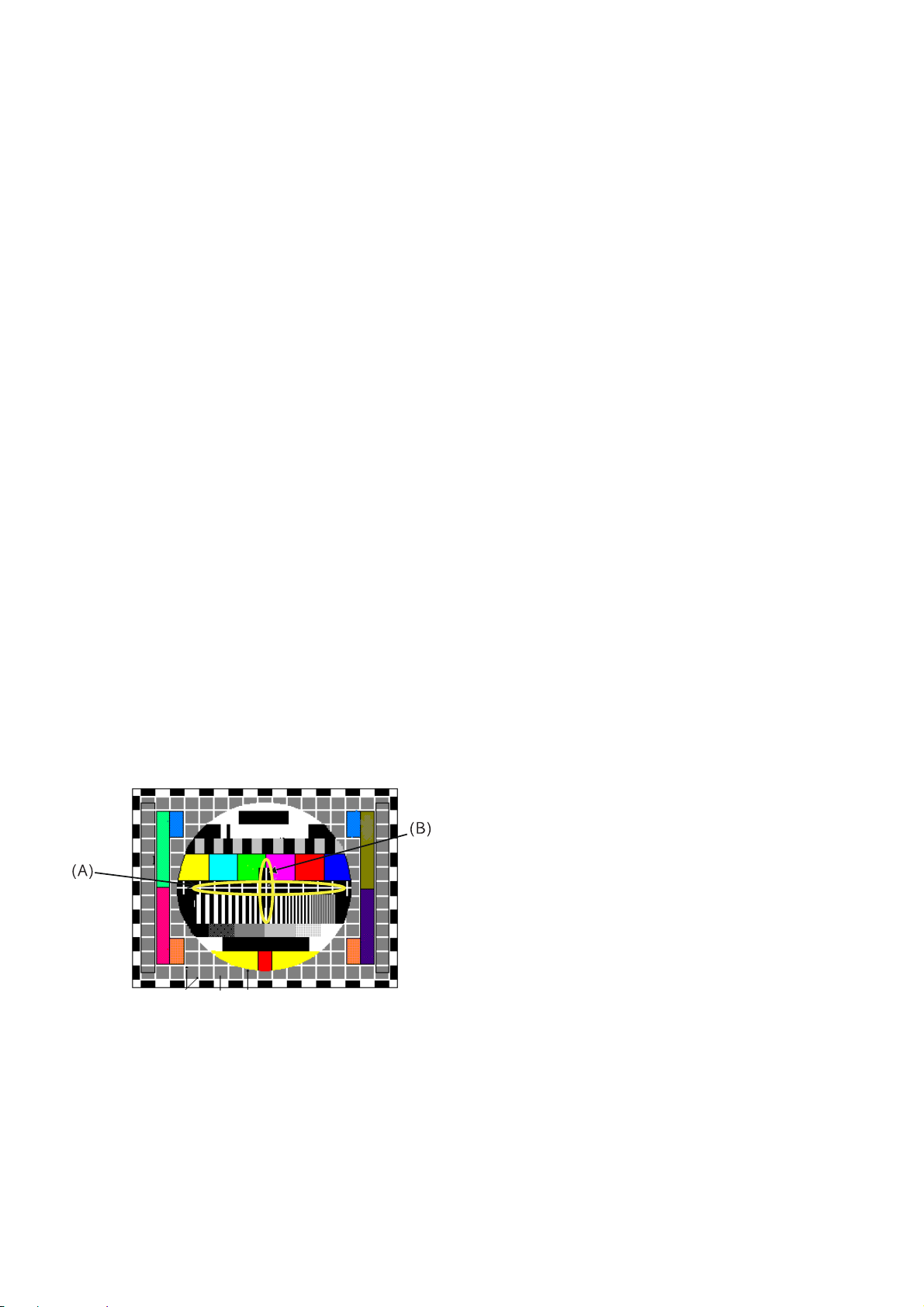
3. Focus adjustment
1. Preliminary steps
(1) Tune the TV set to receive a digital pattern.
(SVC mode: Automatically mode change the STANDARD
MODE)
2. Adjustment
(1) Adjust center focus volume of FBT for the best focus of
vertical line (B).
(2) Adjust the upper focus volume of FBT for the best focus of
area (A).
(3) Repeat above step 1) and 2) for the best overall focus.
4. Purity & Convergence adjustment
4-1. Color purity adjustment
(1) Magnetic room set to destination magnetic and horizontal
magnetic set to zero.
(2) It makes CPT or CABINET enough to demagnetization.
(3) Self-adjustment: Adjust by input of Green raster signal
Manual-adjustment: Receive the signal of red raster.
(RF: PG50Ch or A/V input: RED pattern)
(4) Loosen fixed screw of DY and closely to CPT funnel part.
(5) Check the center of screen that purity magnet of CPT by
crossing adjustment. At this time, 4 & 6 pole magnet is
located to magnet of nothing.
(6) Move the DY to make equal red on whole screen and it
does not to make the DY by fixed screw after check a
simple color of Red/Green/Blue and white raster whether
or not it is a pollution of color.
(At this time, take care raster of screen and DY must fixing in
the condition which maintains a horizontality.)
(7) Check the TV set by move direction.
4-2. Convergence adjustment
These adjustments can the best condition of focus after
finished purity adjustment.
(1) Receive the signal of cross hatch that color is black.
(2) Adjust brightness and luminosity till dot appear 9 ~12.
(3)Open angle of the two tab of 4 pole magnet by isogonic
angle and accord with vertical line of red and blue color in
the middle of screen.
(4)Maintain as angle of 3) and rotate the tab to accord with
vertical line of Red and Blue color in the middle of screen.
(5) Open angle of the two tab of 6 pole magnet by isogonic
angle and accord with vertical line of Red/Blue and Green.
(6) Maintain as angle of 5) and rotate the tab to accord with
horizontal line. In case of twisted horizontal line,repeat
adjustment of 3) ~ 5) remembering the movement of
Red/Green/Blue color.
(7) Move the DY to best condition of convergence and attach
the CPT to a rubber-chock for fixed DY.
4-3 Screen voltage adjustment
1. Preliminary steps
(1) Turn on the TV set.
(2)
This adjustment should be performed after warming up for
more than 15 minutes.
2. Adjustment
(1) Adjust in RF non-signal.
(2) Press the ADJ key of SVC remote controller to make
horizontal line.
5. White balance adjustment
This adjustment should be perfomed after screen adjustment.
This adjustment set the self-adjustment rule.
1. Test Equipment
(1) Automatic White balance meter: Incase of self-adjustment
(2) White balance meter(CRT Color Analyzer, CA-100): 1 EA
(3) A SVC remote controller.
ADJUSTMENT INSTRUCTION
2. Preliminary steps
(1) Tune the TV set to receive an 100% white pattern.
(2) This adjustment should be perfomed after screen voltage
adjustment.
3. Adjustment
(1) Press the CH D ,E key to select adjustment item.
(2) Press the VOL F ,G key to change data.
(3) Adjustment preliminary steps.
a.In items of picture adjustment,adjust until “CONTRAST”
and “BRIGHT” become 45 Ft_L(153Cd/m
2
).
b. Press the SVC key to enter adjustment mode.
c. Adjust the Y value of High Light with R-DRIVE and
adjust the X value with B-DRIVE until they have the
color coordinate of High Light as below.
d. In items of picture adjustment,adjust until “CONTRAST”
and “BRIGHT” become 4.5 Ft_L(15.4FT-L).
e. Enter the adjustment mode by pressing the SVC key.
f. Adjust the Y value of Low Light with R-CUTOFF and
adjust the X value with B-CUTOFF until they have the
color coordinate of Low Light as below.
g.Repeat adjusting until the color coordinate of High and
Low Light is satisfied.
h.Check the color coordinate of adjusted condition with
white balance meter.
- 9 -
SERVICE1
Item
CR(0~511)
CG(0~511)
CB(0~511)
WR(0~511)
WG(0~511)
WB(0~511)
SBRI(-255 ~ 254)
YCDEL
PH 32” FLAT
256
256
256
256
256
256
20
-2
SS 29” FLAT
256
256
256
256
256
256
20
-2
SS 28” FLAT
256
256
256
256
256
256
20
-2
Remark
LOW LIGHT adjument
LOW LIGHT adjument
LOW LIGHT adjument
HIGH LIGHT adjustment
HIGH LIGHT adjustment
HIGH LIGHT adjustment
SUB BRIGHT adjustment
OFFSE DATA
IIC WRITE
EEPROM
R AMP
0
30,31
R CUT
3
2A,2B
B AMP
1
34,35
B CUT
2
2E,2F
SUB BRIGHT DATA SAVE
SUB ADD
START BIT
STOP BIT
1C8
8
0
1C3
8
0
1CA
8
0
1C5
8
0
SUB ADD
Color temperarure.
13000K
9000K
X coordinate
266 ± 8
288 ±8
Y coordinate
273 ± 8
295 ± 8
Remark
Non EU(except model)
EU (RE,RL model)
IIC DATA SETTING
SLAVE ADDRESS(WRITE) SUB BRIGHT CONTROL DATA SPEED
IC 8A EEPROM A0
2
- 10 -
6.Deflection & POP position setting data
adjustment.
6.1 Adjustment preparation
(1) Deflection setting data adjustment is operate by SVC
communicator.
(2) Enter the adjustment mode by pressing SVC key.
(3) Enter the deflection mode by pressing ADJUST key.
(4) Use the CH D ,E key to select adjustment item.
(5) Use the VOL F ,G key to increase/decrease data.
(6) Tune the TV set to receive PAL-B/G Digital pattern.
6.2 Adjustment
(1) VL(Vertical Linearity) adjustment:
Adjust the top & bottom size of inner circle to be equal.
(2) VA (Vertical Amplitude) adjustment:
Adjust so that the circle of a digital circle pattern should be
located interval of 6~7mm from the effective screen of the
CPT.
(3) SC (Vertical S correction) adjustment:
Adjust so that all distance between each lattice width of
top/center/bottom are to be the same.
(4) VS (Vertical Shift) adjustment:
Adjust so that the geometric vertical center line is in accord
with vertical center line of CPT.
(5) HS(Horizontal Shift) adjustment:
Adjust so that the geometric horizontal center line is in
accord with horizontal center line of CPT.
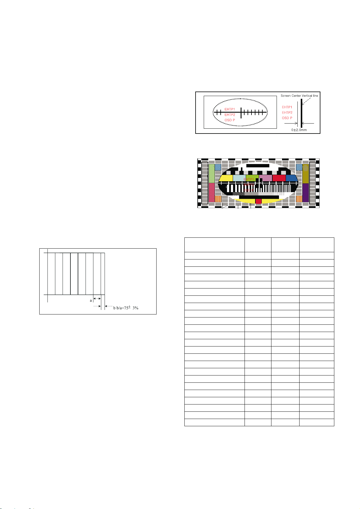
(6) EW(East-West Width) adjustment:
Adjust until the outmost left and right lattice of received
pattern is accord with 75% of other lattice width.
(7) ET(East-West Trapezium) adjustment:
Adjust to make the length of top horizontal line same with it
of the bottom of horizontal line.
(8) EP (East-West Parabola) adjustment:
Adjust so that middle portion of the outermost left and right
vertical line look like parallel with vertical lines of the CPT.
(9) CRNU(Upper Corner Correction) adjustment:
After finished EP adjustment,adjust vertical line of left-
top,right-top of screen to the best straight line.
(10)CRNL(Lower Corner Correction) adjustment:
After finished EP adjustment,adjust vertical line of left-
bottom ,right-bottom of screen to the best straight line.
(11) BOW adjustment
A standard is not changing the dafault value.
(12) Angle adjustment.
When you adjust the angle,adjust correctly raster of
left/right screen.
(13) CRNU6(6’ th Order Upper Corner Correction) adjustment
After finished EP adjustment,adjust vertical line of left-
top,right-top of screen to the best straight line.
(14) CRNL6( Lower Corner Correction) adjustment:
After finished EP adjustment,adjust vertical line of left-
bottom ,right-bottom of screen to the best straight line.
(15) OSD P (OSD POSITION) adjustment.
Adjust so that the character “2” of “EHTP2” is in accord with
right of Screen Center Vertical line after finished (1)~ (14)
adjustment. ( Refer to <figure.1> and <figure.2>.)
SERVICE 2 standard DATA
<figure.1>
<figure.2>
Variable
range
-128~127
-128~127
-128~127
-256~255
-512~511
-256~255
-128~127
-256~255
-128~127
-128~127
-512~511
-512~511
-128~127
-128~127
0~2047
0~511
-512~511
-512~511
-512~511
-512~511
0~511
-511~512
-511~512
-15~15
PHILIPS
32”FLAT
0
10
20
0
-152
5
0
234
4
5
2
1
-1
-1
250
60
-61
-20
-97
-22
0
-20
-40
0
S/S
29” FLAT
0
19
30
5
-198
-13
0
228
6
6
0
0
-1
-1
250
60
-61
-20
-97
-22
0
-20
-40
0
S/S
28” FLAT
0
49
20
0
-180
0
0
239
2
3
0
0
-1
-1
250
60
-61
-20
-97
-22
0
-20
-40
0
Item
VL
VA
SC
VS
HS
EW
ET
EP
CRNU
CRNL
BOW
ANGLE
CRNU6
CRNL6
EHTTH
EHT
EHTV1
EHTV2
EHTH1
EHTH2
EHT F
EHTP1
EHTP2
OSD P
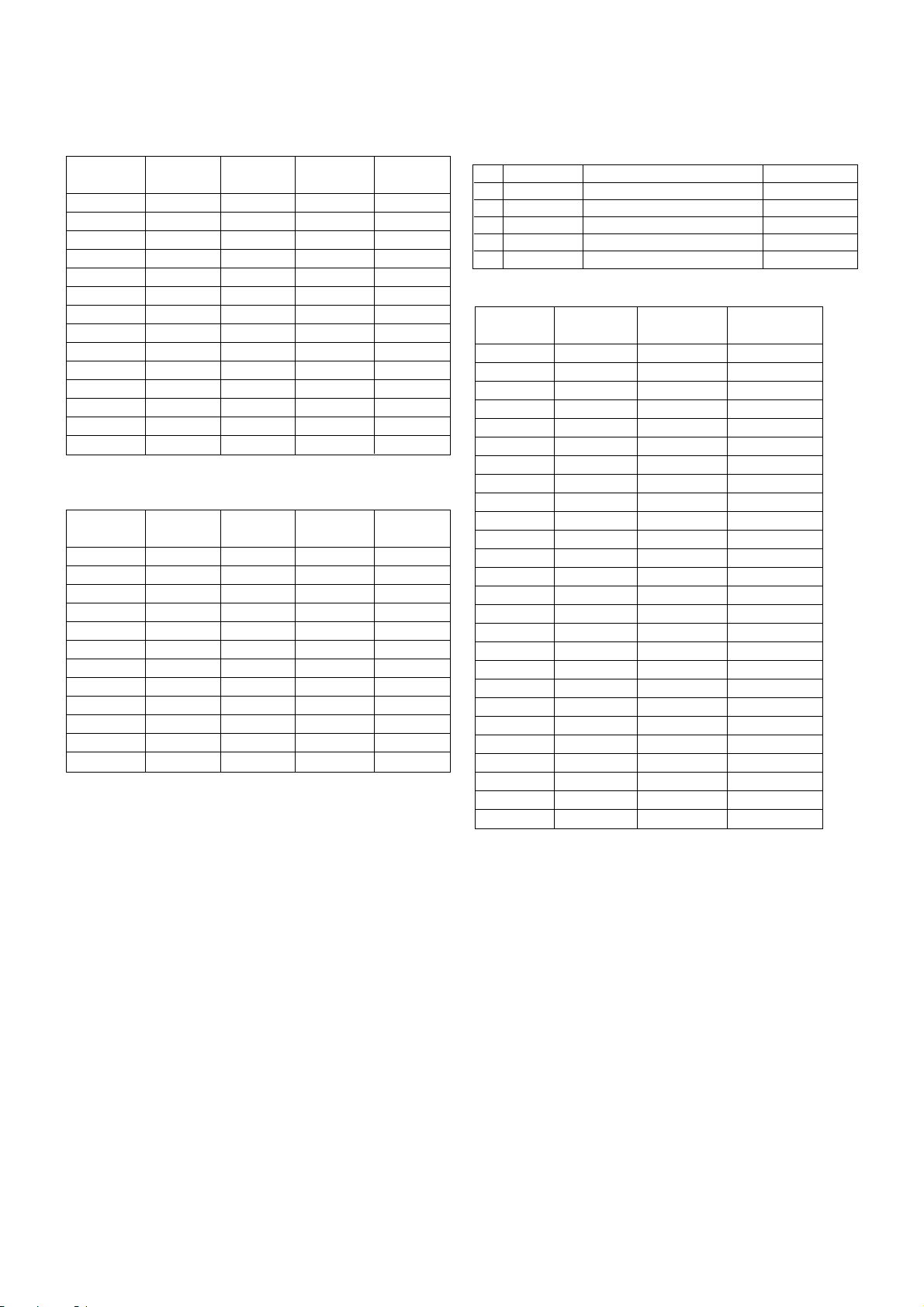
SERVICE 3 standard DATA
SERVICE 4 standard DATA
29” Model:
Adjustment must adjust to the N50Hz(Only PAL mode).
W50Hz,N60Hz and W60Hz need not adjustments.(Only 29”
model)
28”/32” WIDE Model:
14:9,4:3 MODE H-SH(H-SHIFT) adjustment addition.
Adjust “H-SHIFT” of 14:9 and 4:3 by 50Hz.
* Caution: Adjustment of 50 Hz is 16:9’s standard format.
When the adjustment is 50Hz wide mode, you must be done
re-check.
At this time, ZOOM1 and ZOOM2 Mode need not
adjustments. Because it can automatically correct in 16:9
mode.
When you want to re-adjust after deflection adjustment,
adjustment is finished after always re-adjustment.
Screen OSD FONT status and adjustment in H-Shift ARC
SVC adjustment.
Deflection adjustment standard DATA
Adjust in PAL100Hz and PAL50Hz,NTSC60Hz and 480I
needed not adjustment.
- 11 -
PHILIPS
32”FLAT
413
128
50
50
496
85
400
113
200
7
4
30
23
14
S/S
29” FLAT
413
128
50
50
496
140
400
230
200
5
4
30
23
15
S/S
28” FLAT
413
128
50
50
496
135
400
200
200
5
4
20
23
14
Item
IBRM
WDRM
CGAIN
WGAIN
MWDR
BCLTH
BCLTC
BCLGA
BCLC
SVDEL
SVD
SVG
VBSO
TML
PHILIPS
32”FLAT
20
83
17
102
102
230
0
45
25
9
11
252
S/S
29” FLAT
20
83
17
102
102
230
0
45
25
9
11
252
S/S
28” FLAT
20
83
17
102
102
230
0
45
25
9
11
252
Item
FP
NP
SP
S1 VOL
S2 VOL
AGC-L
VPC-L
M-STR
M-HMC
M-HP
M-LP
M-LIM
No.
1
2
3
4
5
ARC MODE
16:9
14:9
ZOOM1
ZOOM2
4:3
SVC OSD FONT(50Hz,PAL)
50W
50 149
50 Z1
50 Z2
50 N
H-SHIFT
Adjustment
Adjustment
Adjustment X
Adjustment X
Adjustment
Item
VL
VA
SC
VS
HS
EW
ET
EP
CRNU
CRNL
BOW
ANGLE
CRNU6
CRNL6
PFGHE
PFGHB
EHTTH
EHTS
EHTV1
EHTV2
EHTH1
EHTH2
EHT F
EHTP1
EHTP2
OSD P
Variable
range
-128~127
-128~127
-128~127
-256~255
-512~511
-256~255
-128~127
-256~255
-128~127
-128~127
-512~511
-512~511
-128~127
-128~127
0~1024
0~1024
0~2047
0~511
-512~511
-512~511
-512~511
-512~511
0~511
-511~512
-511~512
-15~15
PAL
100Hz
0
10
20
0
-152
5
0
234
4
5
2
1
-1
-1
0
0
250
60
-61
-20
-97
-22
0
-20
-40
0
480I
0
10
20
0
-152
5
0
234
4
5
2
1
-1
-1
0
0
250
60
-61
-20
-97
-22
0
-20
-40
0
- 12 -
3.POP POSITION adjustment. (For PIP MODEL)
(1) Press the YELLOW key of SVC remocon to change POP
mode.
(1) POS adjustment ( H POSITION)
- Adjust POS to the inseparable border between main screen
and POP.
*Caution: Adjustment of this mode only adjust to PAL 50Hz of
main screen. But,you must re-check whether or not it is
PAL mode.
(2) Double Window(POS V) vertical location adjustment
- Adjust POS V to be the same vertical location of main screen
and double window.
* Caution: Adjustment of this mode only adjust to PAL50Hz of
main screen. In case of NTSC60Hz, the adjustment needs
not.
(3) POS 50 adjustment
- Change the main input to PAL signal and then adjust POS50
to identity of vertical location.
(4) POS 60 adjustment
- Change the main input to NTSC signal and then adjust
POS60 to identity of vertical location.
6.
OPTION Adjustment
6-1. Preparation for Adjustment
1) This option adjustment decides funtion in accordance with
model.
Press the SVC TX adjustment button(IN-START button) at
SVC mode,then adjust the option at OPTION 1,2,3,4 mode.
2) Mark the option adjustment data like [111,11,111,11] in BOM.
6-2. Adjustment Method
1) Input data directly by the buttons corresponded with
OPTION1 ??(0~63), OPTION2 ??(0~63), OPTION3
???(0~127).
2) Option4???(0~116) controls correspondinglines directly relate
with OSD and TXT LANG.
3) Select each OPTION function by the CH Up/Down button and
then set up each OPTION by the VOL Up/Down button.
[63,56,112,201]
OPTION 1
OPTION 2
OPTION 3
OPTION 4
D D D D
O Mark of BOM
LEVEL PART NO. SPECIFICATION DESCRIPTION
1. 3141VMN382A MAIN[63.56.112.201] CHASSIS ASSY
The OPTION 1 data is 113,OPTION 2 data is 63,the
oOPTION 3 data is 112,the OPTION 4 data is 201 in this
model.
 Loading...