

Page 1

DREAM RF RTU SYSTEM
GUIDE
Generations III, IV, IV.V
TALGIL COMPUTING & CONTROL LTD.
NAAMAN CENTER, HAIFA - ACCO ROAD
ISRAEL
P.O. BOX 775 KIRYAT MOTZKIN 26119
TEL: 972-4-9506051 , 9506052
FAX: 972-4-8775949
2014
Page 2

contents
1. SYSTEM OVERVIEW............................................................................................................ - 4 -
2. SETTING UP AN RF RTU SYSTEM .................................................................................... - 7 -
2.1 SETTINGS TO BE DONE AT THE HOST CONTROLLER .................................................. - 8 -
2.2 SETTING UP THE INTERFACE AND THE RF MASTER ................................................... - 9 -
2.3 SETTING UP THE RF SLAVE ............................................................................................ - 11 -
2.4 SETTING UP THE RF RTU BASE ...................................................................................... - 12 -
2.4.1 Setting the RTU address ............................................................................................ - 13 -
2.4.2 Defining the polling rate ............................................................................................ - 13 -
2.4.3 Setting the layer ......................................................................................................... - 13 -
2.4.4 Setting up a repeater .................................................................................................. - 14 -
2.4.5 Functions of the jumpers ........................................................................................... - 15 -
3. THE VARIOUS MODES OF OPERATION ...................................................................... - 15 -
3.1 START-UP MODE ......................................................................................................... - 15 -
3.2 NORMAL MODE ........................................................................................................... - 15 -
3.3 RF TEST MODE ............................................................................................................. - 15 -
3.4 WHEN LOOSING COMMUNICATION ......................................................................... - 16 -
3.5 TESTING INPUTS AND OUTPUTS ............................................................................. - 16 -
3.6 LOW BATTERY INDICATION ....................................................................................... - 17 -
4. READING ANALOG INPUTS BY RF RTUS .................................................................... - 18 -
4.1 SETTING THE INTERFACE FOR ANALOG INPUTS .................................................. - 18 -
4.2 SETTING THE RTU FOR ANALOG INPUTS ................................................................ - 18 -
4.3 SETTING THE DREAM FOR READING RF ANALOG INPUTS .................................. - 19 -
5. USING RFPROG FOR PROGRAMMING THE RTU ...................................................... - 20 -
5.1 ANALOG INPUTS PARAMETERS ............................................................................... - 21 -
5.2 THE SOLENOIDS ACTIVATION PULSE PARAMETERS ........................................... - 22 -
5.3 INPUTS PULSE DIVISION ........................................................................................... - 22 -
5.4 THE AUTO CLOSE PARAMETERS ............................................................................. - 22 -
6. SOUNDS and LED LIGHTS ................................................................................................ - 23 -
6.1 RTU+SLAVE during START UP .................................................................................... - 23 -
6.2 RTU BASE+SLAVE during normal communication ...................................................... - 23 -
6.3 BASE+SLAVE while losing communication ................................................................... - 23 -
6.4 BASE+SLAVE during RF test - COMMUNICATION OK .............................................. - 23 -
6.5 BASE+SLAVE during RF test – NOT RECEIVING ....................................................... - 24 -
6.6 No communication between BASE and SLAVE .............................................................. - 24 -
6.7 BASE during inputs test .................................................................................................. - 24 -
6.8 BASE during outputs test ................................................................................................ - 24 -
6.9 BASE when battery becomes low .................................................................................... - 25 -
- 2 -
Page 3

6.10 INTERFACE+MASTER during normal operation - RF OK .......................................... - 25 -
This equipment has been tested and found to comply with the
limits for a Class A digital device, pursuant to Part 15 of the
FCC Rules. These limits are designed to provide reasonable
protection against harmful interference when the equipment is
operated in a commercial environment.
This equipment generates, uses, and can radiate radio
frequency energy and, if not installed and used in accordance
with the instruction manual, may cause harmful interference
to radio communications. Operation of this equipment in a
residential area is likely to cause harmful interference in which
case the user will be required to correct the interference at his
own expense.
Changes or modifications not expressly approved by the
manufacturer could void the user’s authority to operate the
equipment
6.11 INTERFACE not communicating with the MASTER ...................................................... - 25 -
6.12 INTERFACE not communicating with the DREAM ....................................................... - 25 -
6.13 BASE ENTERING PROGRAMMING MODE ................................................................ - 25 -
6.14 SLAVE ADDRESS ZERO ............................................................................................... - 25 -
APPENDIX A - Decimal to binary conversion table .................................................................... - 26 -
APPENDIX B - WIRING..................................................................................................................... 27
Wiring between DREAM – RF INTERFACE (internal) and RF MASTER ....................................... 27
Wiring between DREAM – RF INTERFACE (internal) and RF MASTER ....................................... 27
Wiring between RTU BASE and RF SLAVE .................................................................................... 28
Wiring of Outputs and Inputs into the RTU BASE:............................................................................ 29
APPENDIX C – THE RF EAR............................................................................................................ 30
HOW TO USE THE RF EAR ? ......................................................................................................... 30
The system contains the transmitter module FCC ID: 2AC2T-RF-MODULE-45
- 3 -
Page 4
The RF module 4.5
complies with part 15 of the
FCC rules. Operation is
suitable to the following
conditions:
(1) this device may not
cause harmful interference .
(2) this device must accept
any interference received ,
including interference that
may cause undesired
operation.
1. SYSTEM OVERVIEW
The RF RTU system is designed to work in conjunction with the DREAM irrigation
control system, with the UNILINER, MINILINER and OASIS systems, enabling them
to reach remote Input and Output (I/O) devices by wireless means.
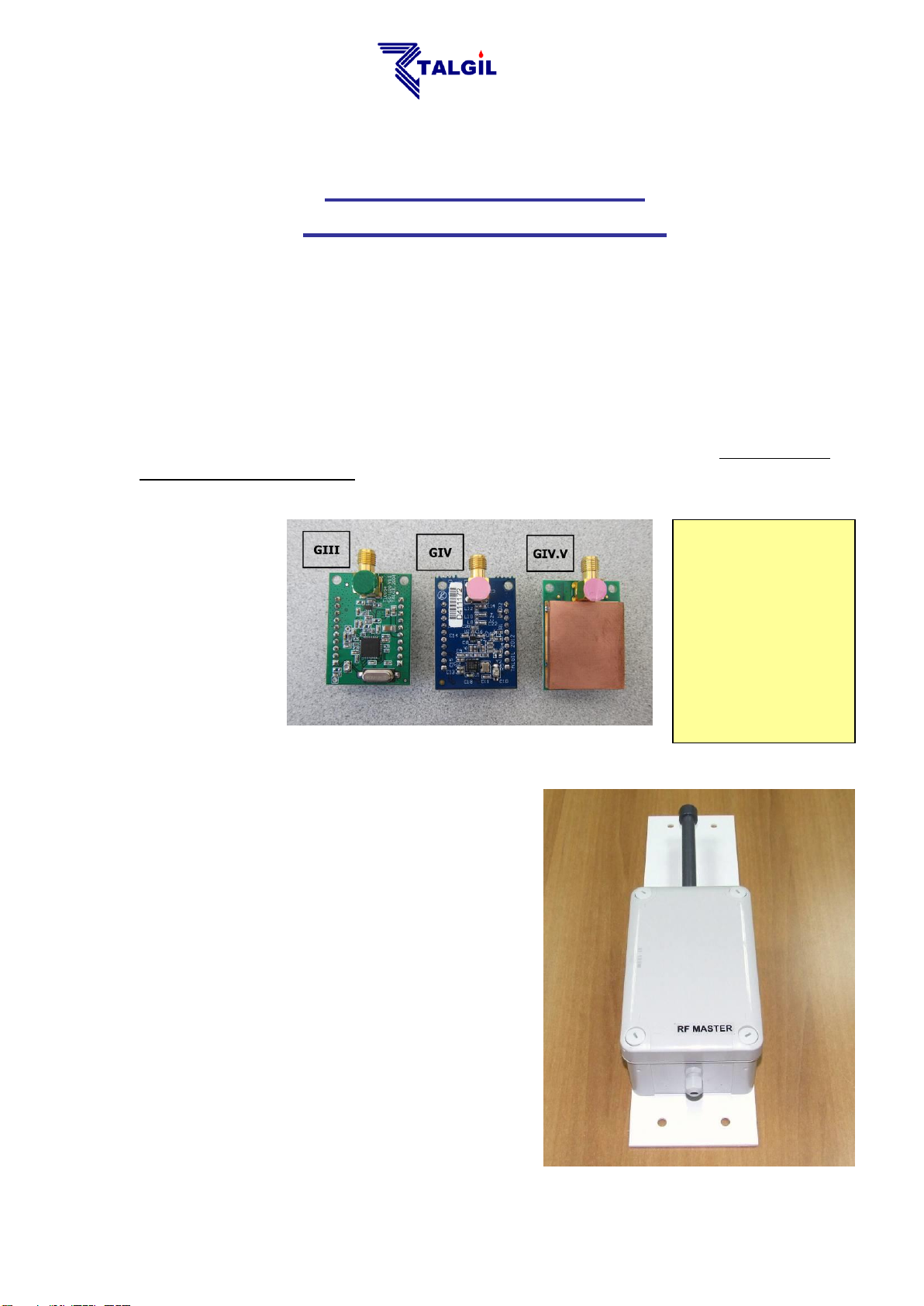
Generations GIV and GIV.V were developed after GIII in order to improve the
frequency separation ability and to cover different frequency ranges. GIII, GIV and
GIV.V are not compatible. The picture below shows the RF units of the three kinds.
Remember - in the same system all RF units must be of the same type:
The RF system consists of the following parts:
1. The RF MASTER – The central
THE RF RTU SYSTEM
GENERATION III, IV, IV.V
receiver/transmitter unit. Includes an RF
unit with antenna, should be installed on top
of a high pole located next to the host
controller.
All the communication with all the RTU
units on site, goes through the RF
MASTER, therefore it should be carefully
positioned at a place from where it may
have a clear line of sight to most of the RTU
units.
- 4 -
Page 5
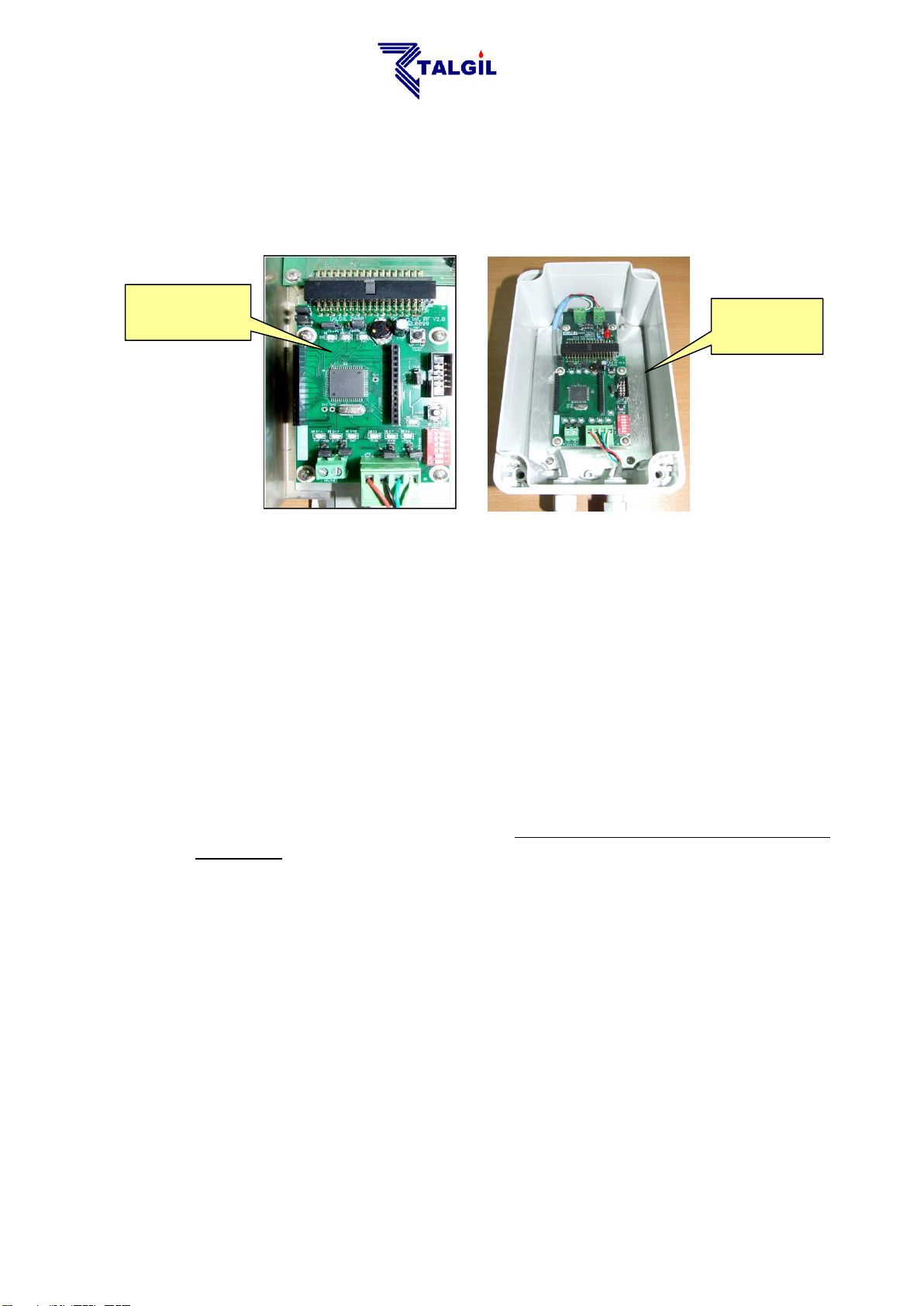
The RF interface
in a separate
enclosure
The RF interface
when located inside
the host enclosure
2. The RF INTERFACE – serves as a link between the RF MASTER and the host
controller. When possible, the RF INTEFACE will be placed inside the enclosure
of the host, otherwise it will have its own enclosure and then the interface will be
connected to the host by a shielded 4 wired cable that can be a few hundred
meters long. Similarly the communication to the RF MASTER uses also a
shielded 4 wired cable.
REMARK: The Oasis RF system does not use an interface.
3. The RF RTU – The RF RTU is the edge unit in the field, that communicates by
radio with the Master, receiving and carrying out commands to open/close
outputs, and reports back the status of inputs.
A single RF channel can handle as many as 60 RTUs.
There are 2 types of RTUs :
a) Modular – the modular RTU may have up to 8 outputs (in steps of 2,4,6,8),
4 digital inputs and up to 4 analog inputs. The outputs activate 2 wired DC
pulse latching solenoids. The ability of reading digital inputs can be added to
any of the 60 RF RTU units however analog inputs are limited to the first 8
RTUs only.
b) Economical– they come in two sizes – with 2 outputs and 2 digital inputs
(2/2), or with 1 output and 1 input (1/1).
The modular RTU consists of 2 parts: one is called the RF SLAVE and the other
is called the RF BASE. The 2 parts are connected by a shielded 4 wired cable
the length of which should not exceed 10 meters.
- 5 -
Page 6
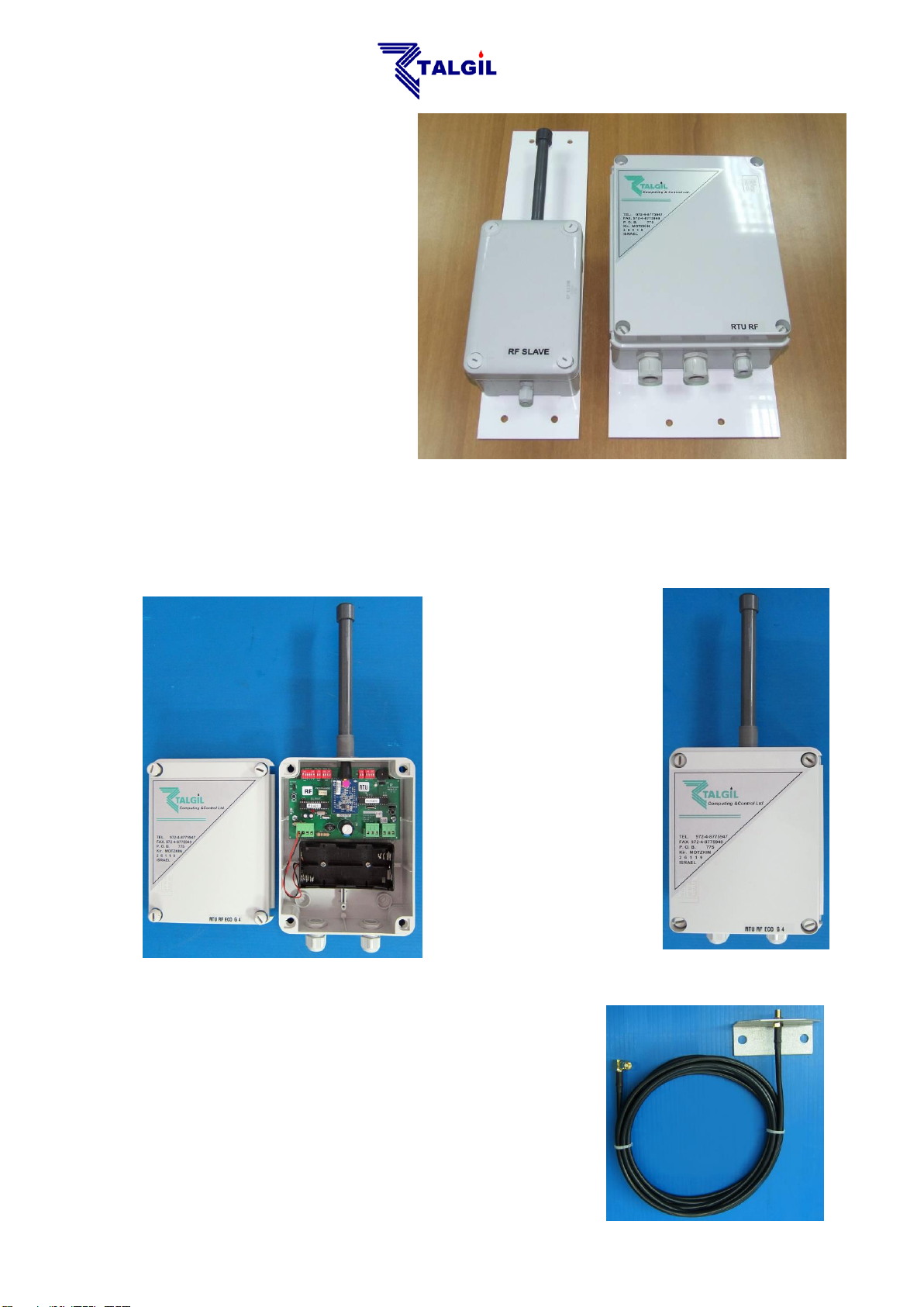
3.1 The RF SLAVE is a
receiver/transmitter unit
including an antenna,
installed on top of a high
pole. The RF SLAVE is
the part of the RTU that
is in charge of the radio
communication between
the RF RTU and the
controller.
3.2 The RF RTU BASE
(EXECUTER) is in
charge of the output and
input activity of the RTU
executing output
commands and reading
the inputs. It is located at the lower part of the pole at a convenient height
for connecting the I/O devices to the unit.
In the Economical RF RTU the SLAVE and the BASE are combined into the same
board:
For practical reasons the Economical RF RTU cannot
be installed in a too high position, because then the
wiring of the outputs and inputs will be too difficult. On
the other hand if we install it in a low position we shall
sacrifice the height of the antenna. In order to solve
this problem we use an antenna extension kit:
- 6 -
Page 7
Connection to
the RF Master
Connection to
the host
Each RF RTU can act also as a REPEATER that can help reaching far RTUs or
help reaching those that are hidden by obstacles. Such a unit can function both as
an RTU and as a REPEATER at the same time.
NOTE : The upper part of the pole holding the RF MASTER and RF
SLAVE units must be made of nonmetallic material, otherwise the radio
signal may suffer some power attenuation. The construction of the
poles must include facilities that will enable easy lowering.
NOTE: Despite the resemblance between the MASTER and SLAVE
units, they are not interchangeable.
The RF RTU can be powered either by dry batteries or by rechargeable battery
charged by solar energy. When powered by dry batteries it will use 6v DC, supplied
by 4 x 1.5v “D” type standard alkaline batteries. When powered by solar energy, the
RF RTU will contain a 12v 1.0Ah rechargeable battery. Regular RTU will use a 2
Watt solar panel, and those who serve as repeaters will use a 5 Watt solar panel.
Assuming ideal conditions, in an area with no obstacles and no interferences, the
distance between the MASTER and a directly communicated RTU can reach about
2.5 -3km. By utilizing a REPEATER, the distance can be doubled.
2. SETTING UP AN RF RTU SYSTEM
The process of setting up an RF RTU system starts at the host controller (DREAM,
UNILINER, MINILINER, OASIS) where some necessary definitions have to be
made through which the controller is informed about the details of the RF system to
be controlled (see below).
An appropriate location should be found for locating the pole of the RF MASTER. It
should be not too far from the host controller and it should be as high as possible in
order to assure a clear line of sight to most of the RTUs in the field. Remember that
the upper part of the pole should be nonmetallic.
The RF INTERFACE that coordinates between the
MASTER and the host controller can be located inside the
host’s enclosure or externally. When external it will come
in a separate box and both sides of the interface the one
that is connected to the host and the one that is
connected to the Master will use a shielded 4 wired cable
for connection. The red and the black wires supply the
power (12v DC) and the green and white wires support
the communication; in both cases the polarity is important,
follow the directions below. The shield will be connected
together with the black wire.
- 7 -
Page 8
Declaring the
number of RF
interfaces
The address
of the RF
interface
The
scanning
rate 10 sec
Out in the field, each RTU BASE (EXECUTER)
and its RF SLAVE counterpart will also be installed
on a pole with the SLAVE unit on top of the pole
and the RTU BASE about 1 meter above ground.
Here again the upper part of the pole, where the
RF slave is located, should be of nonmetallic
material and here too the connection between the
SLAVE and the RTU BASE uses a shielded 4
wired cable.
2.1 SETTINGS TO BE DONE AT THE HOST CONTROLLER
We shall use the DREAM controller for demonstration; however the same kind of
definitions should be done when the host is a UNILINER, MINILINER or OASIS.
The DREAM can handle several RF channels. Each channel will have its own
interface, its own RF MASTER and its own RTUs. The channels must use different
frequencies and they will be recognized by the address given to the RF
INTERFACE of the particular channel.
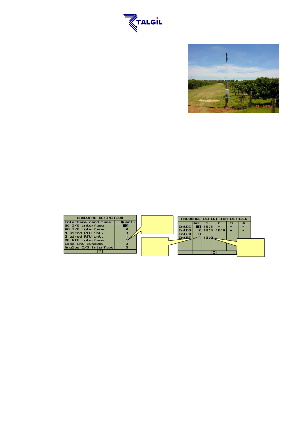
The screens below show the hardware definition to be made at the DREAM in order
to make the DREAM recognize the various interfaces included in the system.
Next to the address of the RF INTERFACE there is a definition of the scanning rate
by which the DREAM is exchanging information with the RTUs.
The following options exist: scanning every 10sec; 5sec; 2.5sec or 1.25 sec. For
energy saving purposes low scanning rate should be preferred, though too low
scanning rate may cause losing pulses of water meters and fertilizer meters having
high flow rates. Therefore the scanning interval should not be longer than the
shortest expected OPEN or CLOSED contact condition. When this condition cannot
be met, pulse dividers should be used (see explanation below). On the other hand,
the scanning rate cannot be decided without taking into consideration the
number of RTUs to be scanned. A scanning rate of 1.25 seconds will limit the
number of RTUs to 7, (the system will recognize RTUs with addresses from 1
to 7). With scanning rate of 2.5 sec, it will recognize RTUs 1 to 15, with
scanning rate of 5 sec, it will recognize RTUs 1 to 31 and with scanning rate
of 10 sec, it will recognize all the range of 60 RTUs.
- 8 -
Page 9
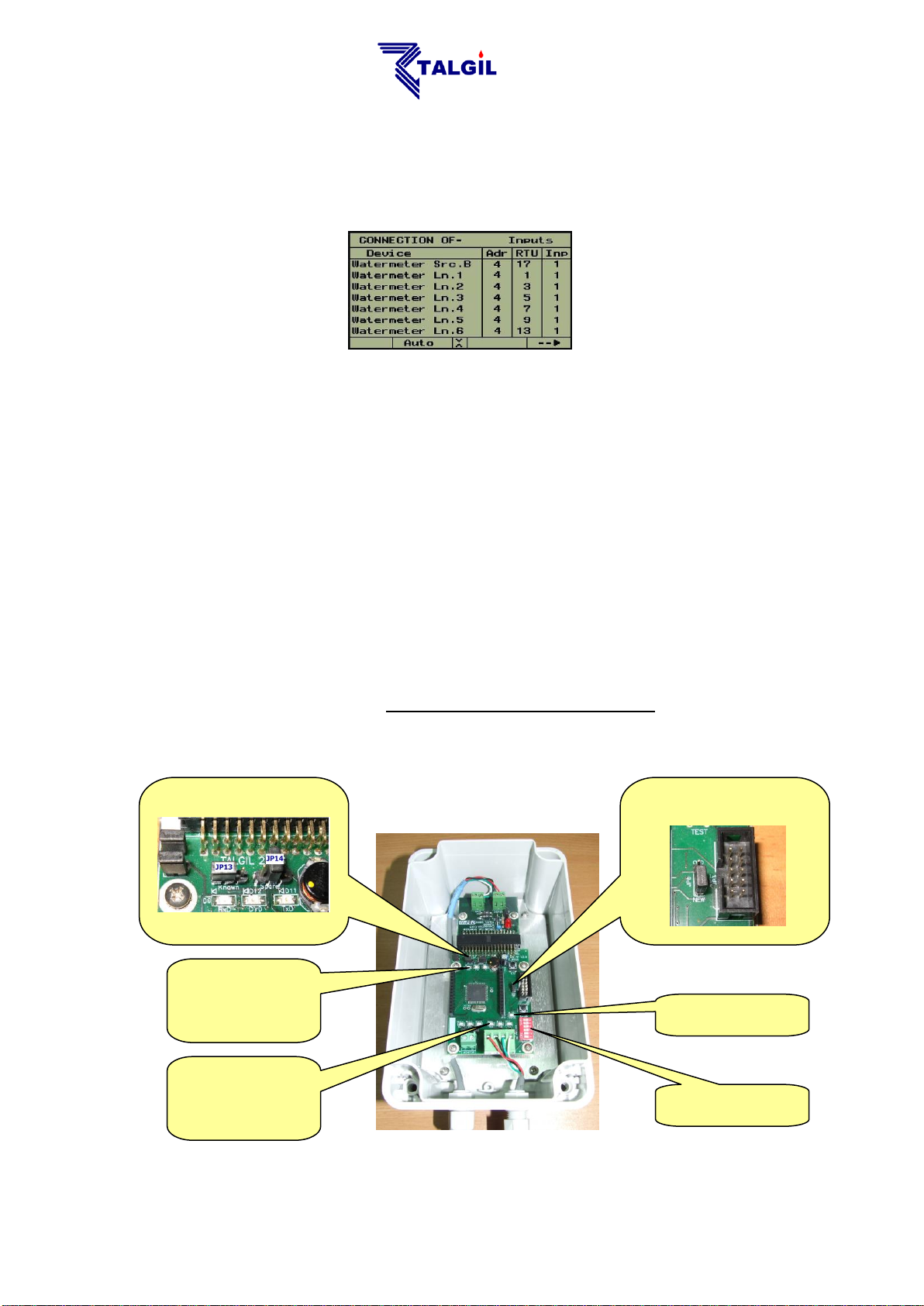
The next step is the definition of the connections table in which the physical
The address switch of
the RF INTERFACE
D5 the status indication
LED.
D3,D4,D7 the LEDs
indicating the
communication with
the MASTER
D9,D11,D12 the LEDs
indicating the
communication with
the DREAM
JP13 indicating analog inputs in
use . JP14 not in use.
JP6 the OLD-NEW selection
jumper
connection point of each I/O device is defined. During this procedure the host is
informed about the addresses of the RTUs existing on the particular channel, and
which I/O devices are connected to each.
2.2 SETTING UP THE INTERFACE AND THE RF MASTER
The RF INTERFACE has been designed to support the GIII and GIV versions, but it
can be compatible with older versions as well. When used with the previous
generation MASTER (up to version 7.8) jumper JP6 should be set to “OLD” position
and when used with a MASTER of version 7.9 or higher, JP6 should be in “NEW”
position (see picture below). Talking about compatibility it must be pointed out that
Master of version 7.9 or higher cannot work properly with interface of the old
generation, therefore if there is a need to replace a Master of version 7.8 or lower
with a Master of version 7.9 or higher it forces the replacement of the old RF
interface to the new one as well.
To indicate that the system contains analog inputs that are supposed to be read
through the RF RTU system, JP13 must be set in left position, leaving the right pin
free as in the picture below.
- 9 -
Page 10
Channel
number
DIP SWITCH S1
pos1
pos2
pos3
pos4
1
OFF
OFF
OFF
OFF 2 ON
OFF
OFF
OFF
3
OFF
ON
OFF
OFF 4 ON
ON
OFF
OFF
5
OFF
OFF
ON
OFF
6
ON
OFF
ON
OFF
7
OFF
ON
ON
OFF 8 ON
ON
ON
OFF
9
OFF
OFF
OFF
ON
10
ON
OFF
OFF
ON
11
OFF
ON
OFF
ON
12
ON
ON
OFF
ON
13
OFF
OFF
ON
ON
14
ON
OFF
ON
ON
15
OFF
ON
ON
ON
16
ON
ON
ON
ON
S1
Setting the channel address is done by use of the Address Dip Switches. The
address must be set according to the address defined at the DREAM (or other host)
controller. Make sure that there is no other interface with the same address. Notice
that the addressing uses binary coding. See “Appendix A” about the binary to
decimal conversion.
The interface board contains a status indication led D5 that supplies the following
information:
Lighting constantly – indicates having no configuration loaded from the
host which is a fault of course.
Blinking fast – indicates having no communication with the MASTER.
Blinking slowly – indicates a mistake in the definition of the analog inputs,
they are supposed to be allocated to a dummy analog interface whose
address must be one above the address of the RF INTERFACE itself.
Light off – indicates normal operation.
The LEDs D9,D11,D12 show the communication with the DREAM. They are
supposed to blink each second. The LEDs D3,D4,D7 show the communication with
the MASTER, when working with an old generation MASTER they will blink fast,
and when working with a new generation MASTER they will blink according to the
selected scanning rate.
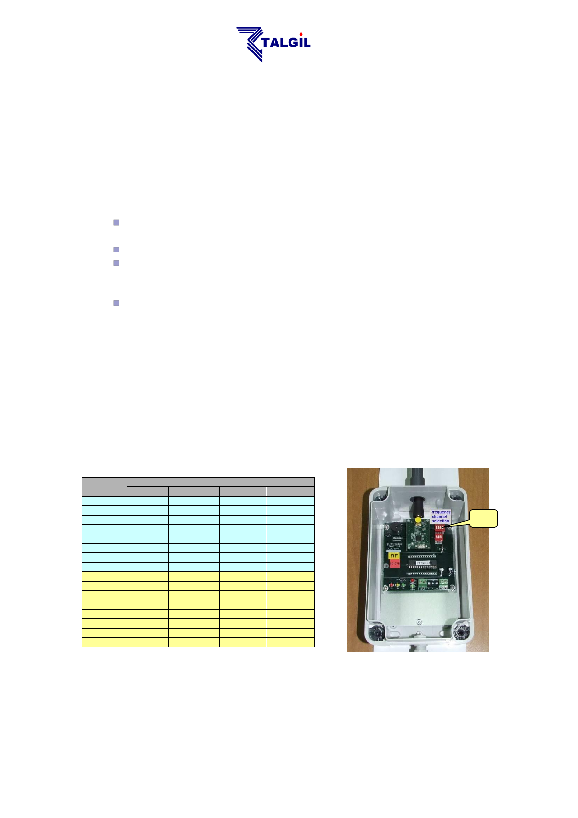
At the RF MASTER the only setting required is for selecting the RF FREQUENCY
to be used. There are 16 frequencies to choose from. The frequency selection must
take into consideration frequencies already being used by neighboring systems.
The selection of the RF frequency is done by the Dipswitch S1 (frequency).
When there are DREAM RF systems in close vicinity, or when a DREAM system
utilizes several channels, one channel may disturb the operation of the others. To
- 01 -
Page 11
Two channels system Three channels system
First
channel
Options for the second channel
First channel
Second
channel
Options for the third
channel
1
07, 08, 09, 10, 12, 13, 14, 15, 16 1 7
13, 14, 15, 16 2 08, 09, 10, 11, 12, 13, 14, 15, 16 1 8
14, 15, 16
3
09, 10, 11, 12, 14, 15, 16 1 9
15, 16 4 10, 11, 12, 13, 14, 15, 16
1
10
16 5 11, 12, 13, 14, 15, 16
2 8 14, 15, 16
6
12, 13, 15, 16
2 9 15, 16
7
01, 13, 14, 15, 16
2
10
16 8 01, 02, 14, 15, 16
3 9 15, 16 9 01, 02, 03, 15, 16
3
10
16
10
01, 02, 03, 04, 16
4
10
16
11
02, 03, 04, 05
12
01, 02, 03, 04, 05, 06
13
01, 02, 04, 05, 06, 07
14
01, 02, 03, 04, 05, 07, 08
15
01, 02, 03, 04, 05, 06, 07, 08, 09 16
01, 02, 03, 04, 05, 06, 07, 08, 09, 10
S1Frequency
setting
eliminate disturbance between the systems the frequency selection should be
according to the following tables:
On the RF MASTER board, there are 5 LEDS. The three LEDS - D3; D4 and D5
indicate the communication with the RF INTERFACE and when the communication
functions properly, they blink fast. The red LED D2 blinks each time the RF
MASTER is calling any of the RTUs, so during each scanning cycle it will blink
several times according to the number of RTUs defined. Each time the RF
MASTER picks up a proper response of an RTU, it makes a short beep sound by its
buzzer , so during each scanning cycle when there are several RTUs responding
to the MASTER each in its turn, there will be a series of beep sounds
…..
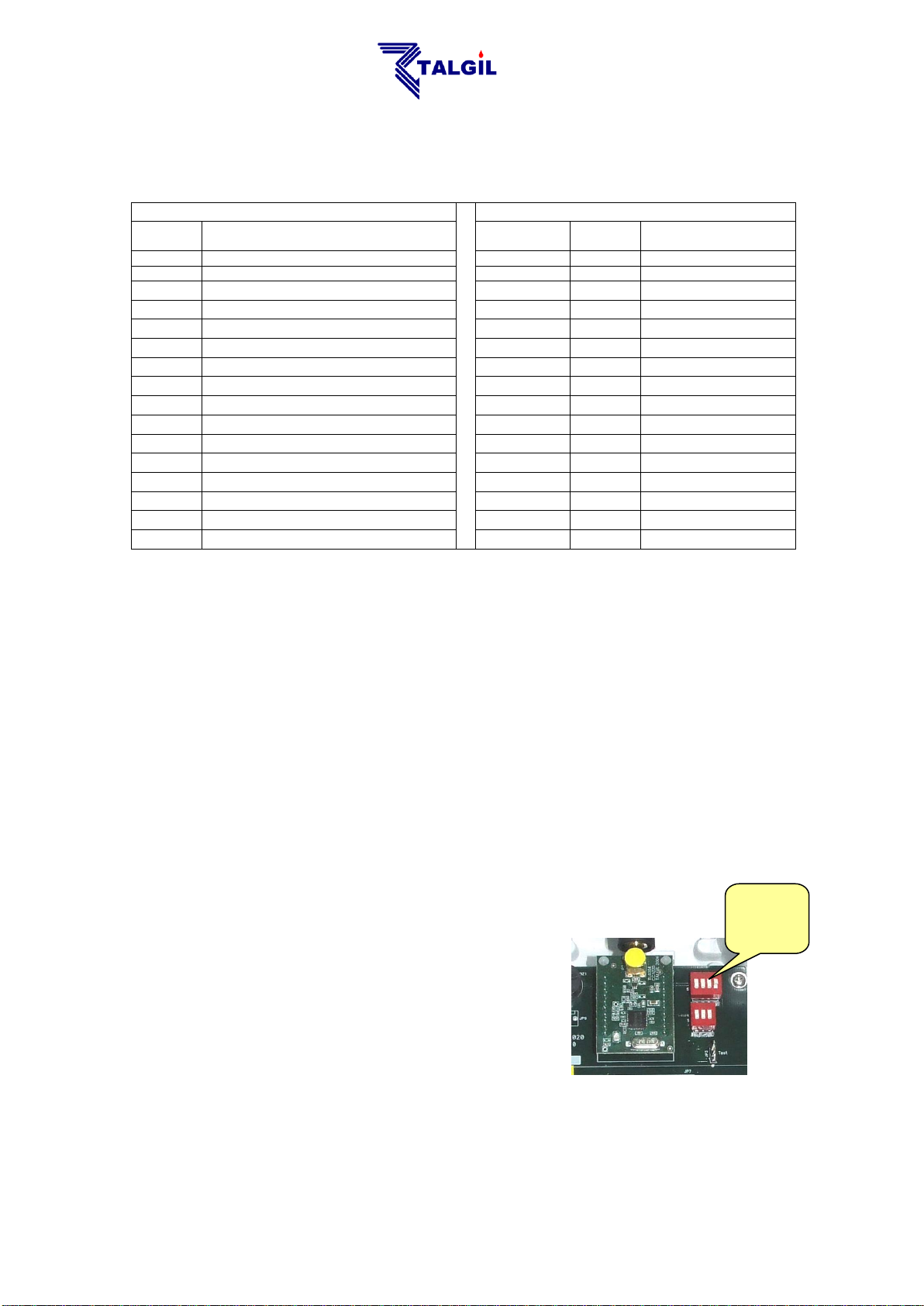
2.3 SETTING UP THE RF SLAVE
The only setting required at the RF SLAVE is the
setting of Dipswitch S1 (frequency). The selected
frequency should be identical to the selected
frequency at the RF MASTER board (see
paragraph above).
REMARK: Starting from GIII the frequency
setting can be done at the RF Base instead of at
the RF SLAVE (see below), this feature enables
changing the frequency without lowering the pole
on which the slave is installed.
- 00 -
Page 12

Layer
RTU
Addres
Polling
rate
Number of RTUs
served by the repeater
Selecting I/O
for test
Buzzer
ON/OF
LED
On/Off
Test I/O
Reset
button
4 digital
inputs
plug-in
board
2 DC latch
outputs
plug-in
board
RF test
jumper
Frequency
selection
Frequency
source
Analog
input type
selection
TH/ other
RTU
Addres
Polling
rate
Frequency
selection
Layer
Number of RTUs
served by the repeater
Test I/O
Selecting I/O
for test
RF test
jumper
Reset
button
2 DC latch
outputs
2 digital
inputs
Buzzer
ON/OF
2.4 SETTING UP THE RF RTU BASE OR THE ECONOMICAL RTU
The following pictures describe the RF RTU base (executer) board, and the
ECONOMICAL RTU board.
The ECONOMICAL RF RTU includes all the functions of the MODULAR RF RTU
except for analog inputs and the ability of expanding the outputs.
- 02 -
Page 13

SW4 – pos 1 pos 2
The polling rate (sec)
Highest RTU address
0 0
10
60
1 0
5
31
0 1
2.5
15
1 1
1.25
7
Before being able to use the RTU there are some necessary settings to be done:
Setting the address of the RTU
Setting the polling rate by which the MASTER is communicating with
the RTUs
Setting the layer of the RTU. The layer defines whether the RTU
communicates directly with the MASTER or through a REPEATER.
(See below the explanation about repeaters).
For RTUs serving as repeaters, it is necessary to define the number of
RTUs that are serviced by the repeater.
Setting the communication frequency. In the old generation the
frequency setting could only be done at the SLAVE board. Starting
from GIII the frequency can be set at the BASE board as well,
therefore the source of frequency need to be selected.
2.4.1 Setting the RTU address
SW1- Defines the address of the specific RTU. The addressing uses binary notation
(see Appendix A about the binary to decimal conversion). Each RTU must have its
own unique address in the range 1 to 60. However the selection of the address
must obey some rules depending on the polling rate and the use of REPEATERS
as explained below.
2.4.2 Defining the polling rate
SW4- Defines the polling rate (known also as scanning rate) by which the MASTER
is communicating with the RTUs. The setting of the polling rate should be identical
in all RTUs and equal to what has been defined at the host controller. The selection
of the scanning rate is not totally free, it must take into consideration the total
number of RTUs that need to be scanned, or more accurately the highest address
to be scanned. The following table shows what will be the highest address
recognizable at any scanning rate selected, and the combination needed at SW4 for
selecting each polling rate.
2.4.3 Setting the layer
SW5- Defines the layer to which the specific RTU belongs. RTU that communicates
directly with the Master without going through a REPEATER is said to belong to
layer “0” and those that communicate through a REPEATER belong to layer “1”.
The directly communicating RTUs will have SW5 set to “00”, and RTUs that
communicate via a REPEATER will have SW5 set to “10”.
- 03 -
Page 14

DREAM
Layer 0
Layer 1
RTU
1
RTU
7
RTU
5
RTU
3
RTU
9
RTU
2
1
2
9
7
5
3
REPEATER
2.4.4 Setting up a repeater
When some RTUs have difficulty to communicate directly with the MASTER
because of a disturbing obstacle or too long distance, there is a necessity to use a
REPEATER. Both the RTU serving as a REPEATER and those using its services,
need to be informed about the arrangement. The following settings are required:
SW3- When SW3 is set to a nonzero value, the RTU becomes a REPEATER and
the value of SW3 represents the number of RTUs using the services of the
REPEATER. The number is expressed in binary notation (see Appendix A about
the binary to decimal conversion). For all the RTUs that are not repeaters, SW3
must be set to "0". In the example below, RTU No 2 is a repeater for 3 units
therefore switch SW3 of RTU No 2 should be set to 3.
Now the question is how does the REPEATER know exactly which RTUs it is
serving? The answer lies in the addresses of those RTUs. The first RTU must have
the address of the REPEATER +1, the second must have the address of the
REPEATER +3, the third will have the address of the REPEATER + 5 etc…
As mentioned above, all RTUs that are directly communicating with the MASTER,
without using a REPEATER, belong to layer "0". The RTUs that are functioning as
REPEATERS belong also to layer "0". Only the RTUs that are communicated via
REPEATERS are considered to belong to layer "1". Each of the units of layer "0"
occupy a single address, but those who belong to layer “1” occupy 2 addresses,
therefore the immediately following address of such RTUs must be skipped.
Therefore RTUs that are communicating via repeaters differ from regular RTUs by
two things: first they belong to layer “1” and second they occupy two addresses
instead of one.
Notice that the first RTU communicating through a repeater will get the
address immediately following the address of the REPEATER. The
other RTUs communicating via the REPEATER will have a gap of 1 from
the former RTU address.
There is no predefined limit to the number of REPEATERS that can be
used in an RF system. However the number of RTUs using the same
repeater is limited to 15.
EXAMPLE – The drawing shows a system
utilizing a repeater. There are 3 RTUs using
RTU No. 2 as a REPEATER, these units
belong to layer "1" while the REPEATER and
the other RTUs belong to layer “0”. The units
that communicate through the REPEATER
have the addresses "3", "5" and "7" and the
addresses "4", "6", "8" are skipped, they cannot
be used.
- 04 -
Page 15

2.4.5 Functions of the jumpers
JP5- When in the upper position, the buzzer is enabled.
JP15- When set to the upper position, a request for RF testing mode is sent to the
DREAM controller. (see paragraph 3.3 below about the RF test mode).
3. THE VARIOUS MODES OF OPERATION
3.1 START-UP MODE
Right after energizing the RTU or after pushing it's reset button there is an
initialization process that starts with a sequence of 3 short and one long beeps
after which the solenoids are closed one by one. Every 15 seconds 2
short beeps will be sounded and every 30 seconds the slave will try to acquire
communication with the MASTER. During the process of acquiring communication
the red LED of the SLAVE turns on indicating that the receiver is open and
listening. This takes about 10 seconds. If the communication is established, the
RTU goes into NORMAL MODE, otherwise it will keep trying to pick up the
communication signal every 30 seconds.
3.2 NORMAL MODE
During normal mode of operation, the RTUs are scanned by the host via the
MASTER one by one in a cyclic manner and in a constant rate. In each cycle, every
RTU is communicated within its allocated timeslot, which is dictated by its address.
During that timeslot, an information exchange takes place, the required state of the
outputs is sent from the host controller to the RTU, and the current state of inputs is
transmitted back to the host controller. The rate of scanning must be identically set
both at the host controller and at each RTU. When the MASTER initiates a
scanning cycle there will be a blink of the MASTER's LED and for each response
received correctly from any RTU, there will be a short beep sounded by the
MASTER's buzzer.
At the other end the RF SLAVE which is dormant between the scanning cycles,
wakes up at the right timeslot and prepares itself for receiving the transmission of
the MASTER. This state is indicated by a blink of the SLAVE's LED . Each time a
successful information exchange takes place there will be a short beep sound
made by the buzzers of both the RTU BASE and the RF SLAVE. If the RTU picks
up the signal from the MASTER but the call was not correctly addressed, it will
sound a double beep . For those who have difficulty hearing the buzzer, the
green LED blinks each time the buzzer sounds.
3.3 RF TEST MODE
The purpose of this test is to check the communication quality between a specific
RTU and the MASTER. Prior to initiating the TEST mode, it must be enabled at the
host controller. When enabled, the request for RF TEST is initiated from the RTU.
By setting JP15 to "RF test" (upper position) a test request signal is sent to the
Master. When the request is received by the MASTER, it is immediately granted
and the RF test starts. During RF TEST mode the regular scanning of all the RTUs
is stopped and the MASTER starts communicating solely with the RTU under test
- 05 -
Page 16

SW6
Input/ Output
under test
000
1
100
2
010
3
110
4
001
5
101
6
011
7
111
8
TE=Test Enabled
TR=Test Request
Signal strength of the RTU picked up by the Master
Signal strength of the Master picked up by the RTU
second by second. The red LED of the SLAVE is constantly ON . The rate of
communication becomes once per second. Each second the Master transmits to
the RTU the signal strength picked up by the Master from the RTU and the RTU
responds by transmitting to the Master the signal strength picked up by the RTU
from the Master. Listening (by the RF Ear) to the exchange of information between
the Master and the RTU under test, one can tell exactly how they hear each other.
00:09:59(097) M->X (15)01 01000010(66) TE AA RSSI=66
00:09:59(147) M<-X (15)01 01000001(65) TR OK RSSI=66
The MASTER will remain in TEST mode until receiving an END OF TEST signal
from the RTU (as a result of removing jumper 15) or until the RF TEST is disabled
by the user at the host controller.
3.4 WHEN LOOSING COMMUNICATION
The reaction of the RTU in case of losing communication with the host can be
initially programmed. The following options exist: 1) to leave the outputs as they are
2) to shut down the open outputs after a predefined delay (Autoclose). Every 30
seconds the unit will try seeking the communication signal of the MASTER. During
this process every 15-second a double beepwill sound, and every 30 seconds
the red LED of the SLAVE will turn on for 10 seconds indicating that the receiver
is open trying to pick up the communication signal. This will continue for 1 hour and
then for energy saving purposes the RTU instead of seeking communication every
30 seconds will start seeking communication only once every hour. When the
communication signal is regained, the RTU returns to its normal state.
Notice that if the MASTER was OFF for more than an hour, then when it
is turned ON again, the RTUs may not respond immediately to the calls
of the MASTER, because they are in energy saving mode. It may take
an hour before they start responding. They can be forced to exit energy
saving mode by pushing the RESET button of the RTU.
3.5 TESTING INPUTS AND OUTPUTS
During test mode the inputs and outputs are tested one by one. The input and
output to be tested is selected by dipswitch block SW6 as follows:
- 06 -
Page 17

INPUT TEST – The test begins by pushing the TEST button SW7. Each change of
state of the selected input will be indicated by a short beep of the buzzer, single
beep for closing the contact and double beep for opening.
OUTPUT TEST – While being in INPUT TEST, pushing SW7 again, will terminate
the INPUT TEST and will start the OUTPUT TEST. An "open" command will be
sent to the selected output followed by a single beep . Another push of SW7
generates a "close" command indicated by a double beep .
Each push of SW7 will switch the solenoid between "open" and "close" positions.
To exit test mode change the position of SW6 or wait 1 minute and it will exit
automatically.
3.6 LOW BATTERY INDICATION
When the battery of an RTU gets too low, there will be a LOW BATTERY indication
both at the RTU and at the host controller.
At the RTU, the low battery is indicated by a sound of 3 beeps sounded
every few seconds.
When is the battery considered low? The system decides on low battery situation by
two criterions: one is the voltage of the battery and the second is the time it takes to
recharge the capacitor after execution of an output command. For example, if the
powering voltage is 6v, then low battery starts to be signaled when the battery
drops to 4.8 volts or when the recharging time is longer than 5 seconds. At this
stage the normal operation continues but the user is informed that the battery
should be replaced. If the voltage drops further to 3.6v the beeping stops and all
outputs will be shut down, since the unit is no longer able to continue
communicating with the MASTER.
- 07 -
Page 18

JP13 indicates that analog inputs
are enabled.
JP6 the OLD-NEW selection
jumper set to NEW
4. READING ANALOG INPUTS BY RF RTUS
Starting from GENERATION III the RF RTU system is capable of reading analog
inputs. This ability is limited to the RTUs addressed 1 up to 8 only. Currently the
only host that recognizes the analog values is the DREAM controller. We shall now
describe the necessary settings and definitions for enabling analog inputs reading
through the RF RTU system.
4.1 SETTING THE INTERFACE FOR ANALOG INPUTS
To enable reading analog inputs the interface must be set as follows:
JP6 – must be set with upper pin free (NEW)
JP13 – must be set with right pin free (ANALOG ENABLED)
The RF MASTER needs no special setting but it must be version 7.9 or higher.
4.2 SETTING THE RTU FOR ANALOG INPUTS
To enable reading analog inputs the RTU must be equipped with a special
EXPANSION BOARD OF ANALOG INPUTS that can handle up to 4 analog inputs.
The analog inputs are additional to the 4 digital inputs that the RTU can read when
equipped with the appropriate plug in board.
The number of analog inputs that will really be used and the way the analog inputs
will be powered is defined by programming the RTU BASE board.
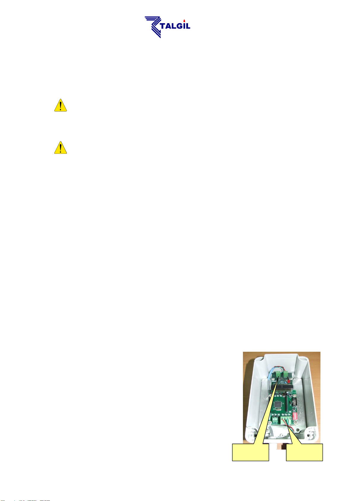
For that purpose a special communication interface and special software “RFProg”
are used.
During programming, the interface will be connected in place of the SLAVE
communication lines as demonstrated below. The PC software “RFProg”
communicates with the RTU through the interface and enables setting the desired
- 08 -
Page 19

Analog
sensor with
2 wires
Analog
sensor with
2 wires
Analog
sensor with
3 wires
Analog
sensor with
3 wires
Expansion
board of
analog inputs
RTU base board
Special
interface for
programming
Plug-in board
of 4 digital
inputs
Plug-in board
of 2 outputs
Internally energized
Externally energized
Connection of the
Special interface to
the RTU in place of
the SLAVE
Internally energized
Externally energized
parameters as explained below at the paragraph about “PROGRAMMING THE
RTU”.
In case of sensor of 4-20 mA, a 221Ω resistor will be used as shown in the picture. Usually the board
will be supplied with the resistors included. In case of 0-5v the resistors should be removed.
+ -
Energy Energy
+ S + S
+ - + - + - + -
S= Signal
- -
- 09 -
Page 20

4.3 SETTING THE DREAM FOR READING RF ANALOG INPUTS
For being able to read analog inputs through the RF RTU system the DREAM host
controller must have the following definitions made:
1. At the NETWORK DEFINITION stage the number of analog inputs must be
declared.
2. At the HARDWARE DEFINITION stage a virtual ANALOG INTERFACE must
be declared and given an address that is higher by 1 than the address of the
RF INTERFACE through which the analog values will be transmitted.
3. At the CONNECTION DEFINITION stage the analog inputs must be defined
as connected to a virtual analog RTU belonging to the channel of the virtual
analog interface but with the same RTU number as the RF RTU to which the
analog input is really connected.
4. The RF RTU to which the analog input is connected must have at least 1
output and 1 digital input allocated to. If such allocation does not really exist,
a dummy output and a dummy digital input must be defined and allocated to
the specified RTU.
5. At the UTILITIES/ANALOG-SENSORS definition the type of each analog
sensor and its scale range should be defined.
The resolution of the analog inputs is 16 bits and they are transmitted
in nibbles of 4 bits per cycle, therefore it takes 4 cycles of
communication to transfer the value of a single analog input and if
there are 4 analog inputs connected to the same RTU it may take at
least 16 communication cycles to transfer 4 analog inputs. If a nibble
was not successfully received by the MASTER it will be requested
again on the next communication cycle.
5. USING RFPROG FOR PROGRAMMING THE RTU
By use of the RFProg (special software for programming the RF RTU) the following
parameters of the RF RTU can be set:
Parameters involved with the analog inputs
Parameters involved with the solenoids activation pulse
Parameters involved with the input pulses division
Parameters involved with the Auto-close in case of losing communication
To prepare for programming the RTU base must be energized by 6-12 volts and
must be put into “programming mode” by holding down the TEST button (SW7) and
then pushing the RESET button (SW2). Being in programming mode is indicated by
a single beep (and single blink ) every 6 seconds. Make sure that the RTU
address is set to a nonzero value. When programming a modular RF RTU the
connector of the cable between the Slave and the Executer must be pulled out.
- 21 -
Page 21

Selected
com port
Read
programmed
parameters
Write
programmed
parameters
Setting
default
parameters
Not in
use
Setting
analog inputs
parameters
Setting the
solenoids
pulse
parameters
Inputs pulses
division
factors
Auto close
cycle and
permission
checkbox
Enabled analog input checkbox
When checked indicates internally energizing
Delay between energizing and reading
Interval between cycles of reading in steps of 10 seconds
The voltage generated for reading
Number of samples used for obtaining the average value
Displaying
statuses of
digital and
analog inputs
Initially the software must be informed about the communication port of the PC to
which the special communication interface is connected. Notice that if the interface
is connected to a USB port, the CONTROL-PANEL/ SYSTEM/ HADWARE/
DEVICE MANAGER should be checked to find out which comport was the USB
serial output allocated to.
5.1 ANALOG INPUTS PARAMETERS
When the checkbox of an analog input is enabled, it indicates that the input is recognized by
the RTU. The input can be energized by external energy source or internally from the RF
RTU itself. When internally energized the energy to the sensor is generated inside the
EXPANSION BOARD OF ANALOG INPUTS and for energy saving purposes it is
supplied to the sensor, each time, only a short while before reading. The cycle of reading,
the voltage supplied and the delay between cycles of reading can be defined as shown
below.
- 20 -
Page 22

Pulse amplitude used for solenoids activation
Pulse width
Enable automatic close in case of communication loss
The period of continuous communication loss that will
cause auto-close of the outputs.
5.2 THE SOLENOIDS ACTIVATION PULSE PARAMETERS
For optimal solenoid activation and for energy optimizing the G III –GIV RF RTU
units enable defining the pulse amplitude and pulse width used for activating the
solenoids.
5.3 INPUTS PULSE DIVISION
Because the rate of pulses arriving to the digital inputs from water meters and
fertilizer meters may sometimes be higher than the scanning rate between the
MASTER and RTUs, it may be needed to count several pulses before transmitting
to the host. This is known as pulse division. The division factor can be set
individually per each input through the following table:
5.4 THE AUTO CLOSE PARAMETERS
It must be decided what will be the reaction in case of loosing communication
between the MASTER and an RTU. Sometimes we would like the outputs to be
closed and sometime we prefer to leave them unchanged. The desired action can
be decided in the following table:
- 22 -
Page 23

6. SOUNDS and LED LIGHTS
Longest beep - (500 msec)
Long beep - (100 msec)
Short beep - (50 msec)
A tick - (5 msec)
Long blink-
Short blink-
6.1 RTU+SLAVE during START UP
USER ACTION: connecting power or pushing the RESET button
RTU ACTION: closing all outputs
RTU BUZZER:
SLAVE LED:
lighting =<10 sec
30 sec
15 sec
15 sec
SLAVE ACTION:
30 sec
seeking communication
every 30 seconds
6.2 RTU BASE+SLAVE during normal communication
SLAVE LED:
1 / 2.5 / 5 / 10 sec
1 / 2.5 / 5 / 10 sec
1 / 2.5 / 5 / 10 sec
…
BASE+SLAVE BUZZERS :
When incorrect RTU address
BASE+SLAVE BUZZERS :
1 / 2.5 / 5 / 10 sec
1 / 2.5 / 5 / 10 sec
1 / 2.5 / 5 / 10 sec
1 / 2.5 / 5 / 10 sec
1 / 2.5 / 5 / 10 sec
1 / 2.5 / 5 / 10 sec
…
…
6.3 BASE+SLAVE while losing communication
SLAVE LED:
BASE BUZZER:
15 sec
SLAVE ACTION:
30 sec
After 1 hour will go into energy saving mode and seek communication only once in an hour
lighting =<10 sec
30 sec
15 sec
seeking communication
6.4 BASE+SLAVE during RF test - COMMUNICATION OK
USER ACTION: JP15 to lower position (upper pin free)
SLAVE LED: lighting constantly
- 23 -
Page 24

BASE+SLAVE BUZZERS :
1 sec
1 sec
…
1 sec
6.5 BASE+SLAVE during RF test – NOT RECEIVING
USER ACTION: JP15 to lower position (upper pin free)
SLAVE LED: lighting constantly
BASE BUZZER :
SLAVE ACTION:
30 sec
…
30 sec
seeking communication
6.6 No communication between BASE and SLAVE
BASE BUZZER :
…
20 sec
6.7 BASE during inputs test
USER ACTION: selecting the desired input by SW6 and pushing TEST button
BASE BUZZER :
USER ACTION: closing the selected input contact
BASE BUZZER :
USER ACTION: opening the selected input contact
BASE BUZZER :
6.8 BASE during outputs test
USER ACTION: selecting the desired output by SW6 and pushing TEST button once for
entering test mode and again for opening the output
BASE ACTION: opens the selected output
BASE BUZZER :
USER ACTION: pushing TEST button again
BASE ACTION: closes the selected output
BASE BUZZER :
USER ACTION: keeps pushing repeatedly the TEST button for opening and closing the
output. For ending the test procedure the RESET button should be
pushed or else there will be an automatic exit after 1 minute of no
changes sensed.
- 24 -
Page 25

6.9 BASE when battery becomes low
BASE BUZZER : that follows any usual beep indicates low battery.
RTU ACTION: When the battery becomes very low closing all outputs one by one and
sounding without any other sounds.
6.10 INTERFACE+MASTER during normal operation - RF OK
INTERFACE D9,D11,D12:
1 sec
1 sec
1 sec
…
INTERFACE D3,D4,D7:
INTERFACE D3,D4,D7:
1 / 2.5 / 5 / 10 sec
1 / 2.5 / 5 / 10 sec
old generation master
new generation master
MASTER LED:
1 / 2.5 / 5 / 10 sec
1 / 2.5 / 5 / 10 sec
1 / 2.5 / 5 / 10 sec
…
MASTER BUZZER : …
… …
…
6.11 INTERFACE not communicating with the MASTER
INTERFACE D5:
blinking fast
…
6.12 INTERFACE not communicating with the DREAM
INTERFACE D9,D11,D12: no blinking
6.13 BASE ENTERING PROGRAMMING MODE
6 sec
6 sec
6 sec
6.14 SLAVE ADDRESS ZERO
1 sec
1 sec
…
- 25 -
Page 26

Decimal address
Binary value to be set by the Dip Switch
Positions: 1 2 3 4 5 6
1
1 0 0 0 0 0
2
0 1 0 0 0 0
3
1 1 0 0 0 0
4
0 0 1 0 0 0
5
1 0 1 0 0 0
6
0 1 1 0 0 0
7
1 1 1 0 0 0
8
0 0 0 1 0 0
9
1 0 0 1 0 0
10
0 1 0 1 0 0
11
1 1 0 1 0 0
12
0 0 1 1 0 0
13
1 0 1 1 0 0
14
0 1 1 1 0 0
15
1 1 1 1 0 0
16
0 0 0 0 1 0
17
1 0 0 0 1 0
18
0 1 0 0 1 0
19
1 1 0 0 1 0
20
0 0 1 0 1 0
21
1 0 1 0 1 0
22
0 1 1 0 1 0
23
1 1 1 0 1 0
24
0 0 0 1 1 0
25
1 0 0 1 1 0
26
0 1 0 1 1 0
27
1 1 0 1 1 0
28
0 0 1 1 1 0
29
1 0 1 1 1 0
30
0 1 1 1 1 0
31
1 1 1 1 1 0
32
0 0 0 0 0 1
33
1 0 0 0 0 1
34
0 1 0 0 0 1
35
1 1 0 0 0 1
36
0 0 1 0 0 1
37
1 0 1 0 0 1
38
0 1 1 0 0 1
39
1 1 1 0 0 1
40
0 0 0 1 0 1
41
1 0 0 1 0 1
42
0 1 0 1 0 1
43
1 1 0 1 0 1
44
0 0 1 1 0 1
45
1 0 1 1 0 1
46
0 1 1 1 0 1
47
1 1 1 1 0 1
48
0 0 0 0 1 1
49
1 0 0 0 1 1
50
0 1 0 0 1 1
51
1 1 0 0 1 1
52
0 0 1 0 1 1
53
1 0 1 0 1 1
54
0 1 1 0 1 1
55
1 1 1 0 1 1
56
0 0 0 1 1 1
57
1 0 0 1 1 1
58
0 1 0 1 1 1
59
1 1 0 1 1 1
60
0 0 1 1 1 1
APPENDIX A - Decimal to binary conversion table
- 26 -
Page 27

APPENDIX B - WIRING
The RF INTERFACE
4 wired shielded cable.
Can be hundreds of meters long.
+12v DC –RED
-12v DC – BLACK
Positive RS485 Communication - GREEN
Negative RS485 Communication -WHITE
Shield – YELLOW GRREN
The RF MASTER
The RF INTERFACE
The RF MASTER
4 wired shielded cable. Can be hundreds of
meters long.
+12v DC –RED
-12v DC – BLACK
Positive RS485 Communication - GREEN
Negativee RS485 Communication -WHITE
Shield – YELLOW GRREN
4 wired shielded cable. Can be hundreds of
meters long.
+12v DC –RED
-12v DC – BLACK
Positive RS485 Communication - GREEN
Negative RS485 Communication -WHITE
Shield – YELLOW GRREN
Wiring between DREAM – RF INTERFACE (internal) and RF MASTER
Wiring between DREAM – RF INTERFACE (internal) and RF MASTER
27
Page 28

4 wired shielded
cable. Maximum
10m long
Shield:
Yellow/ green
6v to SLAVE:
RED = +
BLACK= -
communication to
SLAVE:
GREEN = P
White = N
RTU Base
Wiring between RTU BASE and RF SLAVE
28
Page 29

Wiring of Outputs and Inputs into the RTU BASE:
Plug-in unit of 2 outputs
Plug-in unit of 4 inputs
Locations for more
Output Plug-in units
Locations for more
Output Plug-in units
Locations for more
Output Plug-in units
Each output is 12v 2
wired latching . For
normally open valves
the RED wire goes to
“Out-X” and the
BLACK wire goes to
“C” . For normally
closed valves,
exchange between the
two wires
Each input is
connected by 2 wires .
One wire goes to
“In.X” and the other to
“G” which is common
to all the inputs. The
polarity is of no
importance
Each output is 12v 2
wired latching . For
normally open valves
the RED wire goes to
“Out-X” and the
BLACK wire goes to
“C” . For normally
closed valves,
exchange between the
two wires
Each input is
connected by 2 wires .
One wire goes to
“In.X” and the other to
“G” which is common
to all the inputs. The
polarity is of no
importance. Bottom
row is for inputs 1,3
and upper row inputs
29
Page 30

S1- Selects
frequency
Not
in use
APPENDIX C – THE RF EAR
The RF EAR is a very efficient monitoring tool that supplies valuable
information about the communication between the RF MASTER and the
SLAVES of a particular system to which it is tuned.
The RF EAR contains an RF receiver/transmitter, which resembles the RF
MASTER but functions in a totally different way – it does not transmit anything
but it is continuously open for reception of any transmissions made by the
members of the system. The RF EAR picks up only data transfer using the
communication protocol utilized by Talgil RF systems and only if it is in the
selected frequency. Therefore, the collected information shows the behavior
of the particular system being tested, the information is displayed at a real
time basis on the screen of a mobile PC and it is continuously recorded for
later inspection.
By moving around with the RF EAR and recording the reception quality at the
various RTU locations and at the center, one can identify the weak points of
the system and decide about the solutions.
Usually the receiver/transmitter unit of the RF EAR will be installed on a long
PVC pole that enables raising it high at the places being checked.
HOW TO USE THE RF EAR ?
1. Set the frequency channel of the RF EAR to
the same frequency of the system being
checked.
2. Turn on the power switch of the RF EAR. The unit will start sounding
sequences of short beeps repeated in an interval of the scanning rate.
Each short beep indicates a communication picked up by the unit.
31
Page 31

3. Turn on the laptop and activate the RF EAR software. The following
window will appear:
4. Connect the communication cable of the RF EAR to a serial port of the
laptop, and set the “Comm. Port” of the software accordingly. For those
laptops having no serial port, a USB port with a converter from USB to
RS232 can be used. For GIII the Baud rate setting should be 9600
while for GIV and GIV.V it should be set to 19200.
5. Click on the START button, and the information received by the RF
EAR will start to be displayed as shown in the following screen.
30
Page 32

The time at which
the communication
took place..
The brackets
contain
milliseconds.
M – > X indicates
a call from the
MASTER to
SLAVE - X
The number of the
SLAVE -X is 2.
The number in
brackets is the
selected frequency
channel.
The status of the
outputs-each bit
represents 1 out of
8 outputs. “0”
means closed, “1”
means open.
The RSSI indicates
the strength of the
MASTER’S signal:
For GIII:
41-73 = Strong
34-40 = Medium
20-33 = Low
M <– X indicates
the response from
SLAVE - X to the
MASTER.
The status of the
inputs-each bit
represents 1 out of
4 outputs.
“0” means open
contact, “1” means
closed contact.
The RSSI indicates
the strength of the
SLAVE’S signal:
For GIII:
41-73 = Strong
34-40 = Medium
20-33 = Low
The display is refreshed each scanning cycle.
The drawings of the LEDS on the left side indicate the status of
communication with each of the RF SLAVES (or with each RTU). An RTU,
which responds properly, will be indicated by a LED lighting constantly. An
RTU that did not respond the call of the MASTER will be indicated by a
blinking LED. The RTUs that were not called by the MASTER either because
they are undefined or because the call of the MASTER was not received
remain dark.
On the right side of the window appear rows of characters that describe the
information transmitted either by the MASTER or by one of the SLAVES. The
rows are shifted downward with each new row received by the RF EAR.
The following row contains information about the MASTER’s transmission :
00:01:05(852) M->X (04)02 00000000(00) TD AA RSSI=66
The response of the slave has the following format:
00:01:05(901) M<-X (04)02 00000010(02) NT OK RSSI=66
Notice that in the 8 bits string containing the status of the outputs or the inputs
the rightmost digit represents the lower Output/Input bit.
When an RTU is defined to communicate through a REPEATER, there will be
4 rows describing the process: 1) the call of the MASTER; 2) the transfer of
the call to the SLAVE by the REPEATER; 3) the response of the SLAVE and
4) the transfer of the response to the MASTER by the REPEATER.
32
Page 33

1) MASTER
calling SLAVE 23
2) REPEATER
transfers the call to
SLAVE 23
3) SLAVE 23
responds to the
REPEATER
4) REPEATER
transfers the
response to the
MASTER
In the following example the MASTER is calling RTU 3 which communicates
through a REPEATER:
06:51:48(912) M->X (01)23 00000000(00) TD AA RSSI=39
06:51:48(952) R->S (01)23 00000000(00) TD AA RSSI=53
06:51:49(001) R<-S (01)23 00000000(00) NT OK RSSI=46
06:51:49(041) M<-X (01)23 00000000(00) NT OK RSSI=54
6. The recorded results are stored in text files called rfd0000.txt,
rfd0001.txt, rfd0002.txt etc…Each time we exit and restart the RF EAR
software a new file with a higher index is generated, thus eliminating
the erasure of the previously recorded information. The following rows
are taken from a file of recorded information. Notice that the first row
shows the earliest record and there is exactly 100 milisec between the
calls of the Master to the next RTU.
New loop: 12:47:18
00:00:34(629) M->X (01)01 00000001(01) TD AA RSSI=66
00:00:34(678) M<-X (01)01 00000000(00) NT OK RSSI=66
00:00:34(729) M->X (01)02 00000010(02) TD AA RSSI=66
00:00:34(778) M<-X (01)02 00000000(00) NT OK RSSI=66
00:00:34(829) M->X (01)03 00000100(04) TD AA RSSI=66
00:00:34(880) M<-X (01)03 00000000(00) NT OK RSSI=66
00:00:34(929) M->X (01)04 00000000(00) TD AA RSSI=66
00:00:34(981) M<-X (01)04 00000000(00) NT OK RSSI=66
********
Each asterisk (*) that follows a communication cycle indicates an
additional cycle which ended with identical results to the previous one.
33
Page 34

DIFFERENCES BETWEEN NEW/OLD RTU RF BASE BOARDS
Old RF Base board
New RF Base board GIII
SW3 – in case of
REPEATER, indicates
the number of RTUs
served by the repeater
SW5 –
indicates the
layer the RTU
belongs to
Selecting I/O
for test
Test I/O
button
SW1-Setting
RTU address
SW4-Setting
Polling Rate
Setting the
frequency -**
Selecting
frequency
source: Slave
or RTU-**
Test I/O
button
Selecting I/O
for test
SW1-Setting
RTU address
SW5 –
indicates the
layer the RTU
belongs to
SW4-Setting
Polling Rate
SW3 – in case of
REPEATER, indicates
the number of RTUs
served by the repeater
RF
test
RF
test
LED Enable/
Disable
Selecting between
Analog card or Temp/
Humidity sensor
**- actual from Slave version 7.12 or higher
LED Enable/
Disable
APPENDIX D –
34
 Loading...