

Page 1

Residential Energy Storage Unit
For Photovoltaic Systems
RESU3.3 (R4863P3S)
RESU6.5 (R48126P3S)
RESU10 (R48189P3S)
Installation Manual
June 2016 | Revision 1
Page 2

About this manual
This manual describes how to install the LG Chem RESU®battery pack. Read
this manual before you attempt to install the product, and follow the instruc-
tions throughout the installation process. If you are uncertain about any of the
requirements, recommendations, or safety procedures described in this man-
ual, contact LG Chem immediately for advice and clarication.
The information included in this manual is accurate at the time of publication.
However, the product specications are subject to change without prior notice.
In addition, the illustrations in this manual are meant to help explain system
conguration concepts and installation instructions. The illustrated items may
dier from the actual items at the installation location.
Page 3

Contents
Contents 3
1 Saftey 5
1.1 Symbols on product labels . . . . . . . . . . . . . . . . . . . . . . 5
1.2 Safety instructions . . . . . . . . . . . . . . . . . . . . . . . . . . . 6
General safety precautions . . . . . . . . . . . . . . . . . . . . . . 6
Battery handling guide . . . . . . . . . . . . . . . . . . . . . . . . 7
1.3 Response to emergency situations . . . . . . . . . . . . . . . . . . 7
Leaking batteries . . . . . . . . . . . . . . . . . . . . . . . . . . . 7
Fire . . . . . . . . . . . . . . . . . . . . . . . . . . . . . . . . . . . 8
Wet batteries . . . . . . . . . . . . . . . . . . . . . . . . . . . . . . 8
Damaged batteries . . . . . . . . . . . . . . . . . . . . . . . . . . 9
1.4 Qualied installers . . . . . . . . . . . . . . . . . . . . . . . . . . 9
1.5 Contact information . . . . . . . . . . . . . . . . . . . . . . . . . 9
2 Product Introduction 10
2.1 Technical data . . . . . . . . . . . . . . . . . . . . . . . . . . . . . 10
Dimensions and weight . . . . . . . . . . . . . . . . . . . . . . . 10
Performance . . . . . . . . . . . . . . . . . . . . . . . . . . . . . . 11
Charging cable requirements . . . . . . . . . . . . . . . . . . . . 11
Environmental requirements . . . . . . . . . . . . . . . . . . . . 11
2.2 Features . . . . . . . . . . . . . . . . . . . . . . . . . . . . . . . . 11
2.3 RESU lineup . . . . . . . . . . . . . . . . . . . . . . . . . . . . . . 12
3 Installation 13
3.1 Unpacking the package . . . . . . . . . . . . . . . . . . . . . . . . 13
3.2 Package items . . . . . . . . . . . . . . . . . . . . . . . . . . . . . 14
3.3 Installation materials . . . . . . . . . . . . . . . . . . . . . . . . . 14
3.4 Installation location . . . . . . . . . . . . . . . . . . . . . . . . . . 15
3.5 Tools . . . . . . . . . . . . . . . . . . . . . . . . . . . . . . . . . . 16
3.6 Safety gear . . . . . . . . . . . . . . . . . . . . . . . . . . . . . . . 16
3.7 Installation clearance . . . . . . . . . . . . . . . . . . . . . . . . . 17
3.8 Securing the battery pack to a wall . . . . . . . . . . . . . . . . . 18
3.9 Checking before installation . . . . . . . . . . . . . . . . . . . . . 19
Circuit breaker switch . . . . . . . . . . . . . . . . . . . . . . . . 19
3
Page 4

Contents
Circuit breaker’s trip button . . . . . . . . . . . . . . . . . . . . . 20
Voltage . . . . . . . . . . . . . . . . . . . . . . . . . . . . . . . . . 21
3.10 Connecting the battery pack to the inverter . . . . . . . . . . . . 21
Network cable connection . . . . . . . . . . . . . . . . . . . . . . 22
Ground wire connection . . . . . . . . . . . . . . . . . . . . . . . 23
Charging cables connection . . . . . . . . . . . . . . . . . . . . . 23
3.11 Finalizing installation . . . . . . . . . . . . . . . . . . . . . . . . . 24
3.12 Making a network cable . . . . . . . . . . . . . . . . . . . . . . . 25
3.13 Setting rotary and DIP switches . . . . . . . . . . . . . . . . . . . 26
Setting for communication interface . . . . . . . . . . . . . . . . 26
Setting for battery cell type . . . . . . . . . . . . . . . . . . . . . 27
Settings for CAN bus pins . . . . . . . . . . . . . . . . . . . . . . 27
Setting for terminal resistors . . . . . . . . . . . . . . . . . . . . . 28
4 Commissioning 29
4.1 LED indicators . . . . . . . . . . . . . . . . . . . . . . . . . . . . . 29
4.2 Starting the battery pack . . . . . . . . . . . . . . . . . . . . . . . 29
4.3 Shutting down the battery pack . . . . . . . . . . . . . . . . . . . 30
5 Troubleshooting 31
6 Firmware Update 32
7 Warranty 34
8 Regulatory Approvals 35
A Supported Memory Cards 36
4
Page 5
1 Saftey
CONNECTION KIT
ON
OFF
NOTE
To use rechargeable batteries, you are required to comply with standard AS
4086.2 in Australia and VDE-AR-E2510-2 in Germany.
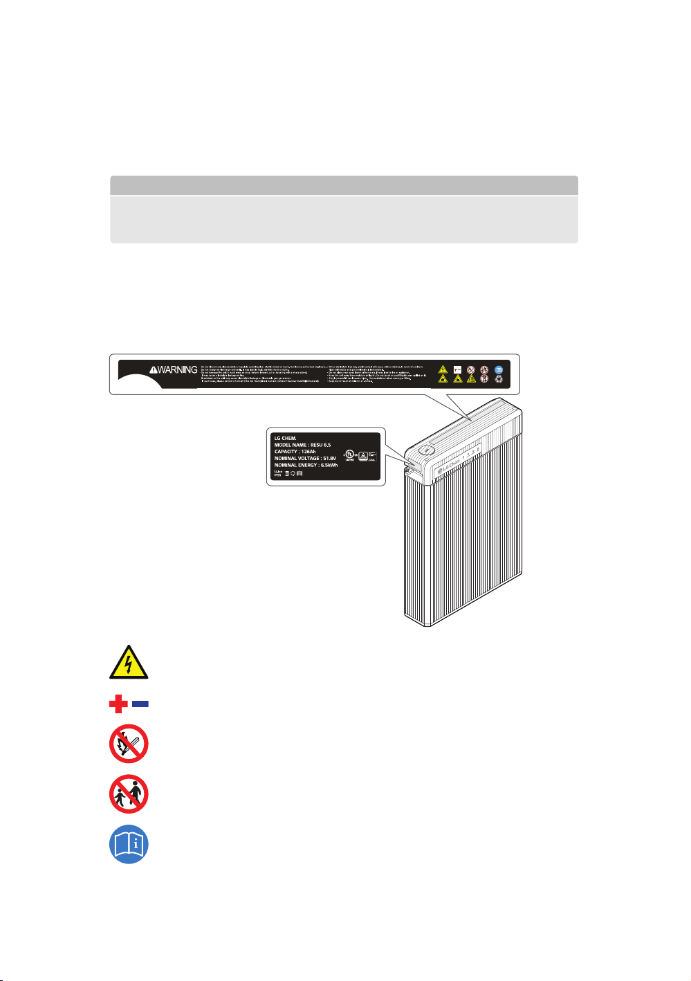
1.1 Symbols on product labels
The nameplate is attached to the left side of the battery pack, and the warning
label is attached to the top.
This battery pack contains high voltage which can cause electric shock
resulting in severe injury.
Make sure that the battery polarity is connected correctly.
Keep the battery pack away from open ame or ignition sources.
Keep the battery pack away from children.
Read the manual before installing and operating the battery pack.
5
Page 6
Saftey
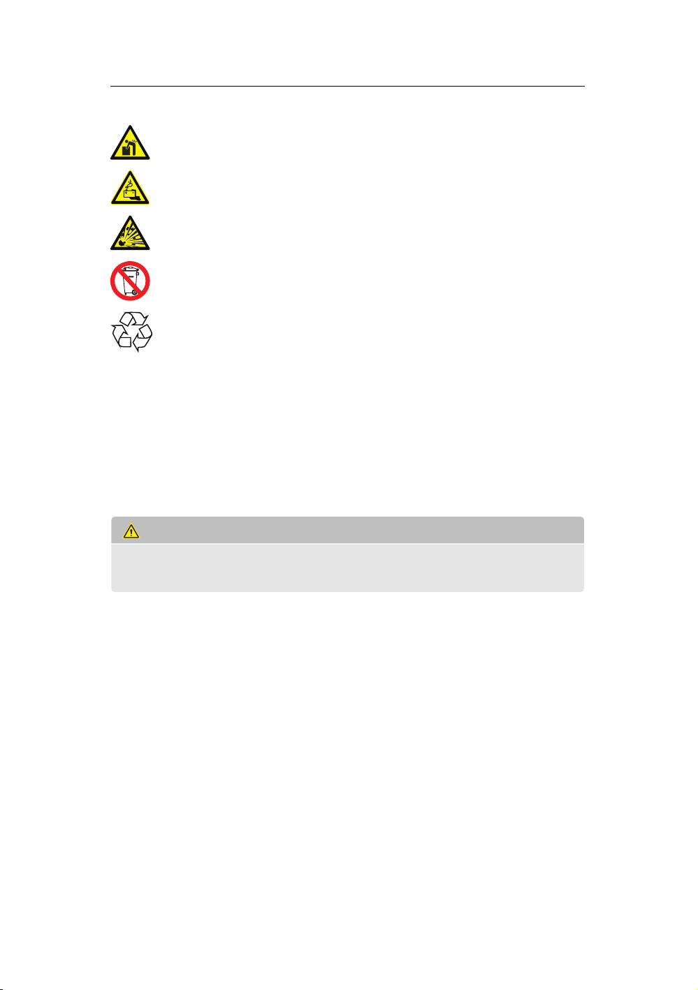
The battery pack is heavy enough to cause severe injury.
The battery pack may leak corrosive electrolyte.
The battery pack may explode.
The battery pack should not be disposed with household waste at the
end of its working life.
The battery pack should be disposed at a proper facility for environ-
mentally safe recycling.
1.2 Safety instructions
For safety reasons, installers are responsible for familiarizing themselves with
the contents of this manual and all warnings before performing installation.
General safety precautions
WARNING
Failure to observe the precautions described in this section can cause seri-
ous injury to persons or damage to property.
Observe the following precautions:
• Risks of explosion
– Do not subject the battery pack to strong impacts.
– Do not crush or puncture the battery pack.
– Do not dispose of the battery pack in a re.
• Risks of re
– Do not expose the battery pack to temperatures in excess of 60°C.
– Do not place the battery pack near a heat source, such as a replace.
– Do not expose the battery pack to direct sunlight.
– Do not allow the battery connectors to touch conductive objects such as
wires.
6
Page 7

Saftey
• Risks of electric shock
– Do not disassemble the battery pack.
– Do not touch the battery pack with wet hands.
– Do not expose the battery pack to moisture or liquids.
– Keep the battery pack away from children and animals.
• Risks of damage to the battery pack
– Do not allow the battery pack to come in contact with liquids.
– Do not subject the battery pack to high pressures.
– Do not place any objects on top of the battery pack.
Battery handling guide
• Use the battery pack only as directed.
• Do not use the battery pack if it is defective, appears cracked, broken or
otherwise damaged, or fails to operate.
• Do not attempt to open, disassemble, repair, tamper with, or modify the
battery pack. The battery pack is not user serviceable.
• To protect the battery pack and its components from damage when trans-
porting, handle with care.
• Do not impact, pull, drag or step on the battery pack. Do not subject it to
any strong force.
• Do not insert foreign objects into any part of the battery pack.
• Do not use cleaning solvents to clean the battery pack.
1.3 Response to emergency situations
The RESU battery pack comprises multiple batteries that are designed to pre-
vent hazards resulting from failures. However, LG Chem cannot guarantee
their absolute safety.
Leaking batteries
If the battery pack leaks electrolyte, avoid contact with the leaking liquid or
gas. Electrolyte is corrosive and contact may cause skin irritation and chemical
burns.
7
Page 8
Saftey
If one is exposed to the leaked substance, do these actions:
Inhalation: Evacuate the contaminated area, and seek medical attention im-
mediately.
Eye contact: Rinse eyes with owing water for 15 minutes, and seek medical
attention immediately.
Skin contact: Wash the aected area thoroughly with soap and water, and
seek medical attention immediately.
Ingestion: Induce vomiting, and seek medical attention immediately.
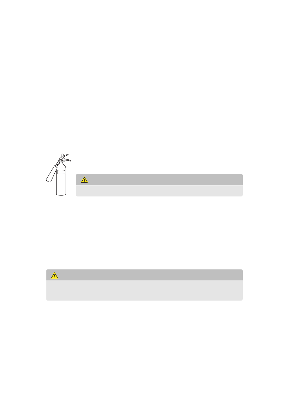
Fire
In case there is a re, always have an ABC or carbon dioxide extin-
guisher.
WARNING
The battery pack may catch re when heated above 150°C.
If a re breaks out where the battery pack is installed, do these actions:
1. Extinguish the re before the battery pack catches re.
2. If it is impossible to extinguish the re but you have time, move the battery
pack to a safe area before it catches re.
3. If the battery pack has caught re, do not try to extinguish the re. Evac-
uate people immediately.
WARNING
If the battery catches re, it will produce noxious and poisonous gases. Do
not approach.
Wet batteries
If the battery pack is wet or submerged in water, do not try to access it. Contact
LG Chem or your distributor for technical assistance.
8
Page 9

Saftey
Damaged batteries
Damaged batteries are dangerous and must be handled with extreme caution.
They are not t for use and may pose a danger to people or property.
If the battery pack seems to be damaged, pack it in its original container, and
then return it to LG Chem or your distributor.
CAUTION
Damaged batteries may leak electrolyte or produce ammable gas. If you
suspect such damage, immediately contact LG Chem for advice and infor-
mation.
1.4 Qualied installers
This manual and the tasks and procedures described herein are intended for
use by skilled workers only. A skilled worker is dened as a trained and qual-
ied electrician or installer who has all of the following skills and experience:
• Knowledge of the functional principles and operation of on-grid systems.
• Knowledge of the dangers and risks associated with installing and using
electrical devices and acceptable mitigation methods.
• Knowledge of the installation of electrical devices
• Knowledge of and adherence to this manual and all safety precautions and
best practices.
1.5 Contact information
Use the contacts below for technical assistance. These phone numbers are
available only during business hours on weekdays.
Telephone Email
Europe +49 (0)162 2970918 aburkert@lgchem.com
USA +1 (0)248 808 0016 jturner@lgchem.com
Asia +82 (0)43 219 2695 soongkyu@lgchem.com
Other regions +82 (0)43 219 2695 soongkyu@lgchem.com
9
Page 10
2 Product Introduction
452
120
654
452
RESU6.5 RESU10RESU3.3
120
401
452
227
483
ON
OF
F
CONNECTION KIT
2.1 Technical data
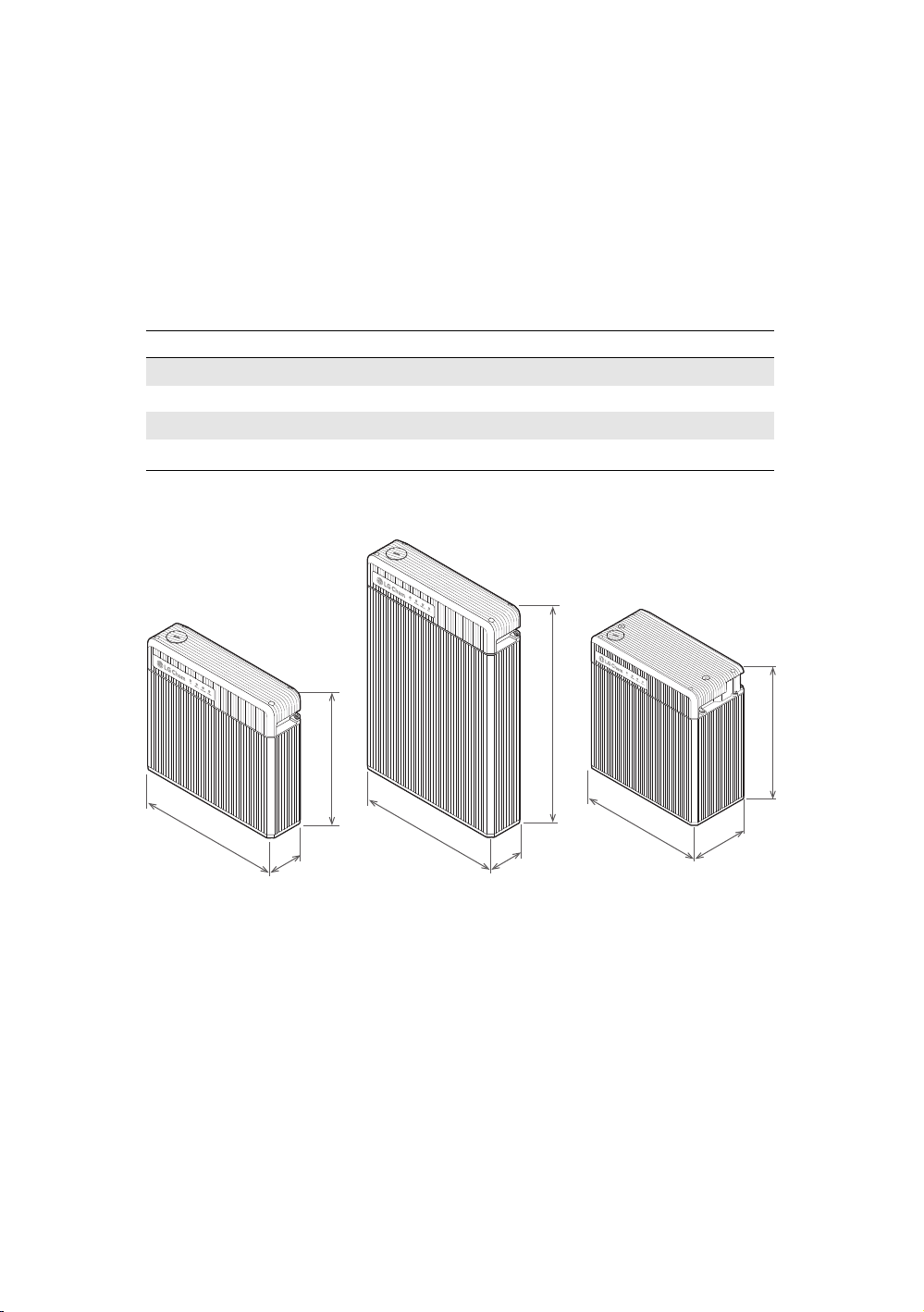
Dimensions and weight
RESU3.3 RESU6.5 RESU10
Length 452 mm 452 mm 452 mm
Width 120 mm 120 mm 227 mm
Height 401 mm 654 mm 483 mm
1
Weight
1
The weight varies slightly depending on the battery cell weights.
31 kg 52 kg 75 kg
10
Page 11

Product Introduction
Performance
RESU3.3 RESU6.5 RESU10
Nominal voltage 51.8 V 51.8 V 51.8 V
Operating voltage 42 to 58.8 V 42 to 58.8 V 42 to 58.8 V
Nominal capacity 63 A·h 126 A·h 189 A·h
Nominal energy 3.3 kW·h 6.5 kW·h 9.8 kW·h
Standard power 1.1 kW 2.2 kW 3.3 kW
Maximum power 3 kW 4.2 kW 5 kW
Peak power for 3 seconds 3.3 kW 4.6 kW 7 kW
Maximum current 71.4 A at 42 V 100 A at 42 V 119 A at 42 V
Charging cable requirements
Conductor cross-sectional area 33 to 50 mm
Cable outer diameter 14 to 21 mm
Cable lug hole size M8
Cable lug width 21 mm
Maximum cable length 5 m per cable
2
Environmental requirements
Available operating temperature −10 to 45 °C (14 to 113 °F)
Optimal operating temperature 15 to 30 °C (59 to 86 °F)
Storage temperature −30 to 60 °C (−22 to 140 °F)
Humidity 5 to 95% (non-condensing)
Altitude Below 2000 m
2.2 Features
The RESU®battery pack has the following features:
Photovoltaic system: This battery pack is designed for photovoltaic system
compatibility.
Battery management system (BMS): The battery pack’s built-in BMS moni-
tors its operation and prevents the battery from operating outside design
11
Page 12
Product Introduction
ON
OFF
CONNECTION KIT
RESU6.5 RESU10RESU3.3
limitations. See Troubleshooting on page 31.
Easy rmware update: The BMS rmware can be updated to the latest ver-
sion. See Firmware Update on page 32.
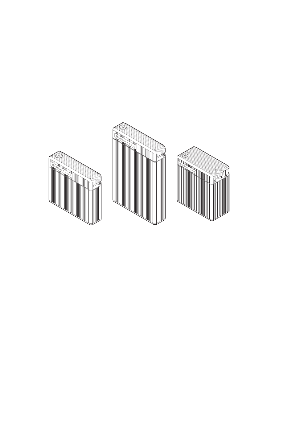
2.3 RESU lineup
There are three RESU battery pack models.
For details about these models, see Technical data on page 10.
12
Page 13

3 Installation
CONNECTION KIT
ON
OFF
WARNING
The battery pack is too heavy for one to carry. Make sure that two or more
persons are available.
3.1 Unpacking the package
1. Cut the packing tape and open the
carton.
2. Remove the honeycomb cushioning
pads.
3. Pull out the battery pack and stand it
upright. Check if the battery pack is
damaged.
4. All the other items are contained in a
box in one corner of the carton. Take
them out and check ifany item ismiss-
ing. See Package items on page 14.
5. Replace the honeycomb cushioning
pads. Keep the carton for future stor-
age or transportation.
13
Page 14

Installation
O
N
O
FF
CONNECTION KIT
3.2 Package items
These items are included.
Battery pack Cable grommets Mounting brackets
Screw anchors Screws Shelf (optional)
The following table lists the numbers of each item included.
Larger grommets for charging cables 2
Smaller grommets for other cables 3
Mounting brackets 2
M6 screw anchors 6
M5 screws 4
If anything is damaged or missing, contact LG Chem or your distributor.
3.3 Installation materials
These installation materials shall be prepared by installers.
• Charging cables
• Network cable
• Ground wire
• RJ45 plug
• Silicone sealant
14
Page 15

Installation
3.4 Installation location
Make sure that the installation location meets the following conditions:
• The building is designed to withstand earthquakes.
• The location is far away from the sea, to avoid salt water and humidity.
• The oor is at and level.
• There are no ammable or explosive materials nearby.
• The normal ambient temperature is between 15 and 30°C.
• The temperature and humidity stays at a constant level.
• There is minimal dust and dirt in the area.
• There are no corrosive gases present, including ammonia and acid vapor.
WARNING
The RESU battery pack is designed to be waterproof and can be installed
indoors as well as outdoors. However, if installed outdoors, do not allow
the battery pack to be exposed to direct sunlight and moisture.
CAUTION
If the ambient temperature is outside the operating range, the battery pack
stops operating to protect itself. The optimal temperature range for the bat-
tery pack to operate is 15°C to 30°C. Frequent exposure to harsh tempera-
tures may deteriorate the performance and lifetime of the battery pack.
15
Page 16

Installation
3.5 Tools
The following tools are required to install the battery pack:
Torque screwdriver Phillips-screwdriver bit Hex-key bit
Phillips-head screwdriver Flat-head screwdriver Wire stripper
Network crimper Voltmeter Tape measure
Drill
Use properly insulated tools to prevent accidental electric shock or short cir-
cuits. Use adjustable tools and measuring instruments that are certied for
precision and accuracy.
3.6 Safety gear
Wear the following safety gear when dealing with the battery pack. Installers
must meet the relevant requirements of international standards, such as IEC
60364, or the domestic legislation.
16
Page 17

Insulated gloves Safety goggles Safety shoes
300 mm
300 mm
9 mm
300 mm
300 mm
300 mm
300 mm
300 mm
9 mm
CONNECTION KIT
ON
OFF
CONNECTION KIT
ON
OFF
3.7 Installation clearance
Installation
Make sure to leave a space of at least 9 mm between the battery pack and the
wall. A clearance of at least 9 mm must be left around the battery pack for
proper cooling.
NOTE
The shelf for the RESU battery pack is sold separately.
17
Page 18

Installation
ON
OFF
CONNEC
TION KIT
ON
O
FF
C
ONNE
C
T
ION K
IT
CAUTION
Make sure that the battery pack is always exposed to the ambient air. The
battery pack is cooled by natural convection. If the battery pack is entirely
or partially covered or shielded, it may cause the battery pack to stop oper-
ating.
3.8 Securing the battery pack to a wall
Secure the battery pack to a wall to prevent the battery pack from moving. If
the battery pack is installed above the oor or on a platform, make sure that
the wall or platform is capable of supporting the battery pack’s weight.
To mount the battery pack to a wall, take the following steps:
1. Remove the top cover. Loosen the four
hex-socket screws at each corner of the
top cover, and then pull it upwards.
2. Perform pre-installation checks de-
scribed in Checking before installa-
tion on page 19.
3. Determine where the mounting brack-
ets are to be placed.
18
Page 19

Installation
ON
O
FF
C
ONNE
C
T
ION K
IT
4. Drill holes in the wall for M6 (¼ in)
screw anchors. The drilling depth
should be at least 50 mm.
5. Drive the screw anchors through the
mounting brackets into the holes.
6. Tighten the screws to a torque of 5
N·m.
7. There are holes for mounting brackets
on the top of the both sides of the bat-
tery pack. Secure the mounting brack-
ets to the holes using the M5 screws.
Tighten them to a torque of 5 N·m.
3.9 Checking before installation
There are things to check before installing the battery pack to ensure that it has
no defects.
CAUTION
Make sure that the inverter is turned o while checking the battery pack.
Circuit breaker switch
At the rst installation, make sure that the circuit breaker switch is in the Trip
position between the ON and OFF positions.
19
Page 20

Installation
ON
O
FF
C
ONNE
C
T
ION K
IT
ON
O
FF
C
ONNE
C
T
ION K
IT
Move the circuit breaker switch to the ON
position.
1. Push the circuit breaker switch to the
OFF position.
2. Without releasing the grip, push it be-
hind the OFF position until it cannot
go any further.
3. Without releasing the grip, push it to
the ON position.
If the switch moves by itself to any of the other positions, do not use the battery
pack. Contact LG Chem or your distributor.
Circuit breaker’s trip button
Make sure that the circuit breaker switch
is put in the ON position, and then press
the circuit breaker’s trip button. If the cir-
cuit breaker switch has not moved to the
Trip position, do not use the battery pack.
Contact LG Chem or your distributor.
20
Page 21

Voltage
ON
O
FF
C
ONNE
C
T
ION K
IT
ON
O
FF
C
ONNE
C
T
ION K
IT
Measure the voltage at the terminal block using a voltmeter.
1. Make sure that the circuit breaker
switch is put in the OFF position, and
then measure the voltage. If the volt-
age is higher than 0 V, do not use the
battery pack. Contact LG Chem or
your distributor.
2. Move the circuit breaker switch to the
ON position, and then measure the
voltage. If the voltage is lower than
38 V, do not use the battery pack. Con-
tact LG Chem or your distributor.
3.10 Connecting the battery pack to the inverter
Installation
WARNING
Make sure that the inverter is turned o before connecting the battery pack
to the inverter.
Before connecting the battery pack to the
inverter, make sure that the circuit breaker
switch is in the OFF or Trip position.
21
Page 22

Installation
ON
O
FF
C
ONNE
C
T
ION K
IT
ON
O
FF
C
ONNE
C
T
ION K
IT
ON
O
FF
C
ONNE
C
T
ION K
IT
Network cable connection
NOTE
The battery pack must be connected to the inverter via a network cable for
proper operation.
1. The smaller grommet is too narrow for
the RJ45 plug to pass through. Make
sure that the network cable from the
inverter does not have an RJ45 plug
at the end. Thread the network cable
through a smaller grommet and then
through the top of the smaller holes.
2. Attach an RJ45 plug to the network ca-
ble using a wire stripper and network
crimper. See Making a network cable
on page 25.
3. Connect the network cable to the com-
munication port.
4. Push the grommet into the hole.
22
Page 23

Installation
ON
O
FF
C
ONNE
C
T
ION K
IT
ON
O
FF
C
ONNE
C
T
ION K
IT
Ground wire connection
NOTE
Grounding between the battery pack and the inverter is not mandatory but
recommended.
1. Thread the ground wire from the in-
verter through a smaller grommet and
then through the bottomof the smaller
holes.
2. Connect the ground wire to the
ground screw, and tighten it to a
torque of 4 N·m The screw type is M5.
3. Push the grommet into the hole.
Charging cables connection
1. Make surethat thecross-sectional area
of the charging cables is 33 to 50 mm2.
Thread the charging cables through
each of the larger grommets and then
through each of the larger holes.
23
Page 24

Installation
ON
O
FF
C
ONNE
C
T
ION K
IT
O
N
O
FF
C
ONNECT
IO
N
K
IT
3.11 Finalizing installation
2. Connect the charging cables to the ter-
minal block.
a) Remove the terminal cover plate,
which is placed over the terminal
block to protect it.
b) Connect the negative cable (−) to
the left terminal and the positive
cable (+) to the right terminal.
Tighten the hex-socket screws to a
torque of 6 N·m.
c) Place the cover back on top.
3. Push the grommets into the holes.
1. Stu the smaller grommets left un-
used with an insulating material like
silicone sealant, and then push them
into the remaining holes.
2. Apply silicone sealant or putty around
the cable at each grommet to prevent
foreign materials from entering the
battery pack.
3. Set the switches as described in Set-
ting rotary and DIP switches on page
26.
4. Start the battery pack as described in
Starting the battery pack on page 29.
5. Place the top cover. Tighten the four
screws at each corner of the top cover.
24
Page 25

Installation
3.12 Making a network cable
Use this method to make a network cable, which is to be connected between
the battery pack and the inverter.
1. Cut cable to needed length.
2. Strip 2.5 to 5 cm of the outer sheath at the end of the cable.
3. Untwist and separate each pair of wires.
4. Arrange the wires in this order:
1) White with an orange stripe
2) Orange
3) White with a green stripe
4) Blue
5) White with a blue stripe
6) Green
7) White with a brown stripe
8) Brown
5. Bring the sorted wires together, and trim them to about 1.4 cm in length.
6. Hold the RJ45 plug with the copper contacts facingup, and insert the wires
into the plug, making sure that they stay aligned and each color goes into
its appropriate channel.
7. Put the plug into a network crimper and squeeze the handles until it clicks.
8. Repeat these steps for the other end of the cable.
25
Page 26

Installation
ON
O
FF
3.13 Setting rotary and DIP switches
Remove the switch cover by pulling it upwards. There are three DIP switches
and three rotary switches.
Switch number Type Label Default
1 DIP SW select 0000
2 DIP Cell select 00
3 Rotary CAN_H 4
4 Rotary CAN_L 5
5 Rotary GND 2
6 DIP Term Res 11
2
2
2
NOTE
If these switches are setincorrectly, communication with the inverter cannot
be established.
Setting for communication interface
Use the SW select DIP switch to set what communication interface is
used by the inverter. This switch is initially set to 00002.
Any other than those given in the following table is regarded as an invalid
setting.
26
Page 27

Installation
Type
LGC Solo
LGC Multi
LGC Smart
Value
0001
0010
0011
2
2
2
Setting
NOTE
For information about compatible inverters and their communication inter-
face, a separate datasheet will be available on request.
Setting for battery cell type
Make sure that the Cell select DIP switch is set to 002.
Bit On O
1 JP3 JH3
2 Unused Unused
Settings for CAN bus pins
Use the CAN_H rotary switch to set which pin is used for CAN
high signal by the inverter. This switch is initially set to 4.
Use the CAN_L rotary switch to set which pin is used for CAN
low signal by the inverter. This switch is initially set to 5.
Use the GND rotary switch to set which pin is used for ground
by the inverter. This switch is initially set to 2.
NOTE
Keep in mind that only 1 to 5 pins can be used.
27
Page 28

Installation
Setting
Example 1
Example 2
CAN_H CAN_L
4
1
5
2
GND
2
3
Setting for terminal resistors
Make sure that the TermRes DIP switch is set to 112.
Bit On O
1 CAN terminal resistor attached CAN terminal resistor unattached
2 Unused Unused
28
Page 29

4 Commissioning
ON
OFF
CONNECTION KIT
4.1 LED indicators
The LED indicators on the front of the battery pack show its operating state:
ON: This indicator is lit when the circuit breaker switch is in the ON position.
Charging: This indicator is lit while the battery pack is charging.
Discharging: This indicator is lit while the battery pack is discharging.
Warning: This indicator is lit when the battery pack is in a warning state. See
Troubleshooting on page 31.
4.2 Starting the battery pack
Put the battery pack in operation by taking these steps:
1. Move the circuit breaker switch to the ON position to turn on the battery
pack.
2. Make sure that the ON indicator is lit. If it stays o, do not use the battery
pack. Contact LG Chem or your distributor.
3. Turn on the inverter.
NOTE
If communication with the inverter is not established within 10 minutes
after the battery pack is turned on, the circuit breaker automatically trips.
29
Page 30

Commissioning
4.3 Shutting down the battery pack
To shut down the battery pack, take these steps:
1. Turn o the inverter.
2. Remove the top cover from the battery pack.
3. Turn o the battery pack by moving the circuit breaker switch to the OFF
position.
4. Make sure that every LED indicator on the battery pack is o.
5. Replace the top cover.
30
Page 31

5 Troubleshooting
Check the indicators on the front to determine the state of the battery pack.
A warning state is triggered when a condition, such as with voltage or tem-
perature, is beyond design limitations. The battery pack’s BMS periodically
reports its operating state to the inverter.
When the battery pack falls outside prescribed limits, it enters a warning state.
When a warning is reported, the inverter immediately stops operation.
Use the monitoring software on the inverter to identify what caused the warn-
ing. The possible warning messages are as follows:
• Battery Over Voltage
• Battery Under Voltage
• Battery Over Temperature
• Battery Under Temperature
• Battery Discharge Over Current
• Battery Charge Over Current
• BMS Internal Communication
• Battery Cell Voltage Imbalance
The abnormal state is cleared when the battery pack recovers normal opera-
tion.
NOTE
For a serious warning, if no proper corrective actions are taken by the in-
verter, the battery pack’s circuit breaker automatically trips to protect itself.
31
Page 32

6 Firmware Update
ON
OFF
CONNECTION KIT
ON
OFF
CONNECTION KIT
It is possible to update the BMS rmware. Use a memory card to update it. A
new rmware may be available from LG Chem website or your distributor.
Prepare a memory card with these properties:
• The capacity of the memory card must not be greater than 32 GB.
• The memory card must be formatted in FAT16 or FAT32.
• It must have only one rmware le in the root directory.
For details about supported memory cards, see Supported Memory Cards on
page 36.
Take these steps to update the rmware:
1. Turn o the inverter.
2. There is a round lid on the left part
of the top cover, covering the memory
card slot below it. Turn the lid coun-
terclockwise and pull it upwards to re-
move it.
3. Insert the memory card into the mem-
ory card slot.
4. Insert the memory card into the mem-
ory card slot.
32
Page 33

Firmware Update
ON
OFF
CONNECTION KIT
ON
OFF
CONNECTION KIT
5. Press and hold the update button be-
side the memory card slot for more
than 3 seconds.
6. The LED indicators ash in cycles un-
til the rmware update is complete.
Only the ON indicator is lit when the
rmware update is successful. If it
fails, the Warning indicator lights for
two seconds. Check the memory card
and try again. If it persistently fails,
contact LG Chem or your distributor.
7. Replace the lid.
8. Turn on the inverter.
33
Page 34

7 Warranty
LG Chem protects this product under warranty when it is installed and used
as detailed in this manual. Violating the installation procedure or using the
product in any way not described in this manual immediately voids all war-
ranties on the product.
LG Chem does not provide warranty coverage or assume any liability for direct
or indirect damages or defects that result from the following causes:
• Improper transportation or storage
• Incorrect installation, wiring or handling
• Non-compliance with LG Chem’s installation or operation manual
• Operating the product in an inappropriate environment
• Incorrect or inappropriate operation
• Insucient ventilation
• Failure to adhere to safety warnings or instructions
• Repairs or modications performed by unauthorized personnel
• Inverter failure or overcurrent.
• Force majeure events
• External inuences, such as unusual physical or electrical stress.
• Use of an incompatible inverter
34
Page 35

8 Regulatory Approvals
Faradic charge eciency (25°C/77°F) 99%
Battery round-trip eciency (C/3, 25°C/77°F) 95%
Expected lifetime at 25°C/77°F More than 10 years
Cycle life (90% DOD, 25°C/77°F) 6000 cycles
Cycle life (80% DOD, 25°C/77°F) 10000 cycles
Communication interface CAN 2.0B
Cooling Natural convection
Battery pack safety CE, RCM, TUV (IEC 62619), UL 1973
Battery cell safety UL 1642
UN number UN 3480
Hazardous materials classication Class 9
UN transportation testing requirements UN 38.3
International protection marking IP55
35
Page 36

A Supported Memory Cards
Most memory cards can be used for rmware update. However, some memory
cards may not be supported, depending on manufacturers and models. These
memory cards are tested and guaranteed to work by LG Chem.
• SanDisk SDHC 4 GB
• SanDisk Ultra SDHC10 8 GB
• SanDisk Ultra MicroSD1 8 GB
• Trenscend SDHC4 32 GB
• Trenscend SDHC10 600x 32 GB
• Transcend Premium 400x MicroSD10 8 GB
• Transcend Premium 400x MicroSD10 16 GB
• Transcend Premium 400x MicroSD10 32 GB
• Toshiba Exceria MicroSD3 32 GB
36
Page 37

Keep this manual for later use.
LG Chem
LG Twin Towers, 128 Yeoui-daero Yeongdeungpo-gu Seoul
07336, Korea
 Loading...