LG REAP10WHE User Manual

NOTCHCELL

Operation Manual

SMD-014-PMB210(V1.0)

Copyright

Copyright of this manual belongs to LG Electronics, Inc.

Reproduction, distribution or revision of part or all of contents in this manual in any form without written permission of LG Electronics, Inc. is prohibited.

Registered Trademark

LG Electronics, are registered trademarks of LG Electronics, Inc.

Other products and company names mentioned herein this manual might be trademarks or trade names of their respective owners.

The results of using the information not mentioned in this manual or the risk of misunderstanding this document remain with the user.

The information in this manual is subject to change due to function enhancement, change of design, etc. If you want the modified manual or have any question on this manual, please contact us with information below:

Address : Customer Support Center, LG Research Complex 1, 533 Hogye 1-dong, Dongangu, Anyang-shi, Kyungki-do, South Korea

Tel : 82-1588-9388

Copyright © 2003 LG Electronics, Inc. All Rights Reserved

1/39

Revision History

Version

Date of revision

Reason for revision

Revision Description


V1.0

01. 04. 2004

First Edition


2/39


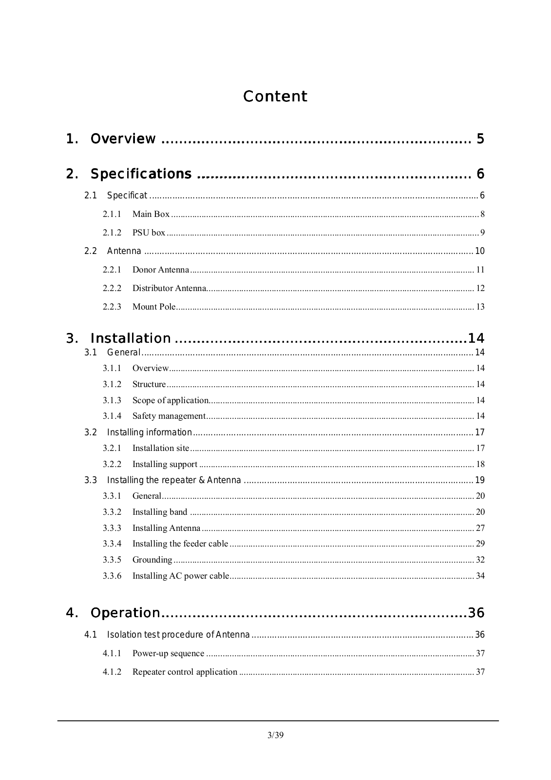
Content


1.

Overview ......................................................................

5

2.

Specifications ..............................................................

6


2.1

Specificat .................................................................................................................................

6


2.1.1

Main Box ....................................................................................................................................

8


2.1.2

PSU box......................................................................................................................................

9


2.2

Antenna .................................................................................................................................

10


2.2.1

Donor Antenna..........................................................................................................................

11


2.2.2

Distributor Antenna...................................................................................................................

12


2.2.3

Mount Pole................................................................................................................................

13

3.

Installation ..................................................................

14


3.1

General ..................................................................................................................................

14


3.1.1

Overview...................................................................................................................................

14


3.1.2

Structure....................................................................................................................................

14


3.1.3

Scope of application..................................................................................................................

14


3.1.4

Safety management...................................................................................................................

14


3.2

Installing information..............................................................................................................

17


3.2.1

Installation site..........................................................................................................................

17


3.2.2

Installing support ......................................................................................................................

18


3.3

Installing the repeater & Antenna ..........................................................................................

19


3.3.1

General......................................................................................................................................

20


3.3.2

Installing band ..........................................................................................................................

20


3.3.3

Installing Antenna .....................................................................................................................

27


3.3.4 Installing the feeder cable .........................................................................................................

29


3.3.5

Grounding .................................................................................................................................

32


3.3.6

Installing AC power cable.........................................................................................................

34

4.

Operation.....................................................................

36


4.1

Isolation test procedure of Antenna.......................................................................................

36


4.1.1

Power-up sequence ...................................................................................................................

37


4.1.2

Repeater control application .....................................................................................................

37

3/39

1. Overview

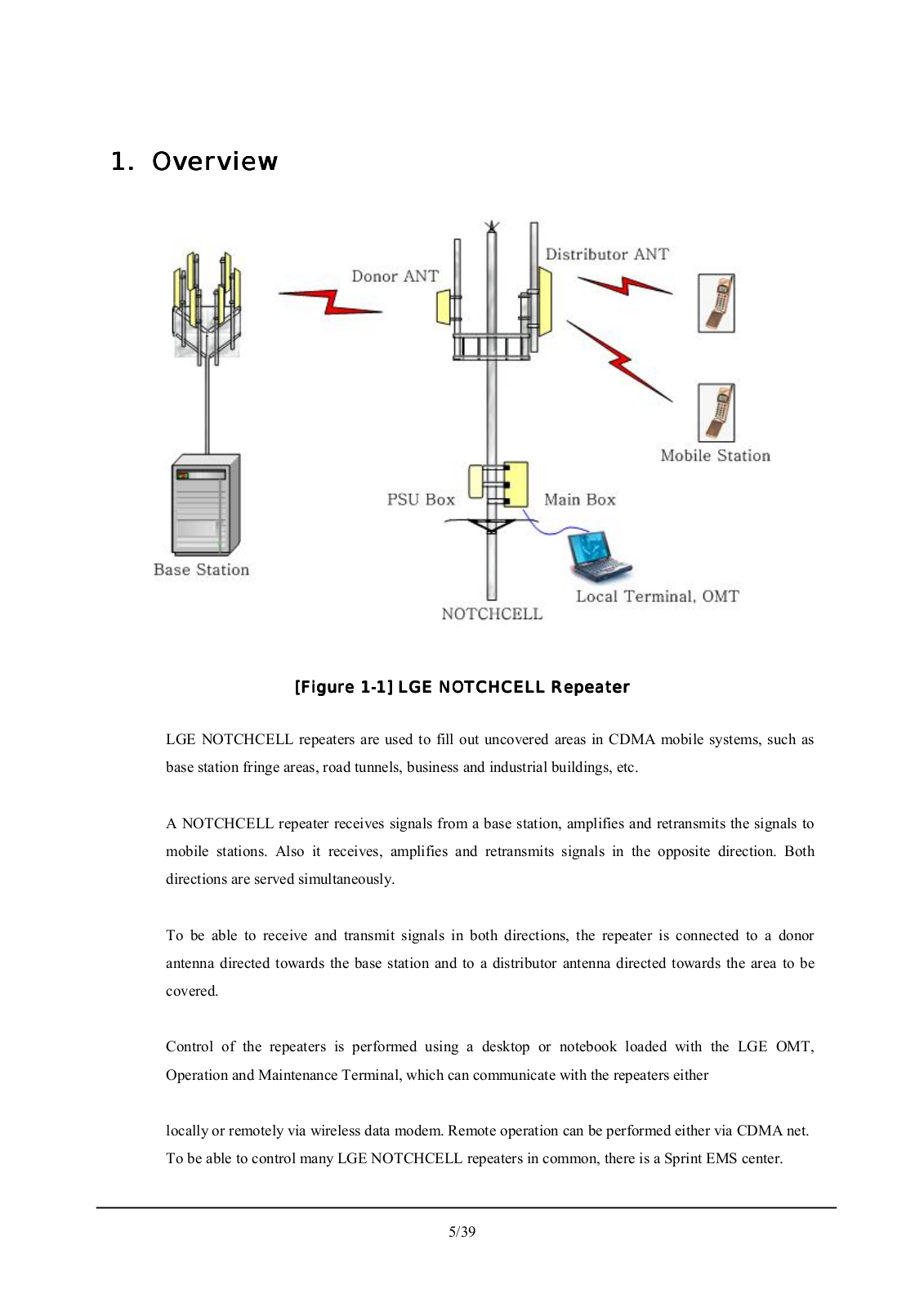
[Figure 1-1] LGE NOTCHCELL Repeater

LGE NOTCHCELL repeaters are used to fill out uncovered areas in CDMA mobile systems, such as base station fringe areas, road tunnels, business and industrial buildings, etc.

A NOTCHCELL repeater receives signals from a base station, amplifies and retransmits the signals to mobile stations. Also it receives, amplifies and retransmits signals in the opposite direction. Both directions are served simultaneously.

To be able to receive and transmit signals in both directions, the repeater is connected to a donor antenna directed towards the base station and to a distributor antenna directed towards the area to be covered.

Control of the repeaters is performed using a desktop or notebook loaded with the LGE OMT, Operation and Maintenance Terminal, which can communicate with the repeaters either

locally or remotely via wireless data modem. Remote operation can be performed either via CDMA net. To be able to control many LGE NOTCHCELL repeaters in common, there is a Sprint EMS center.

5/39

2.

Specifications


2.1

Specificat


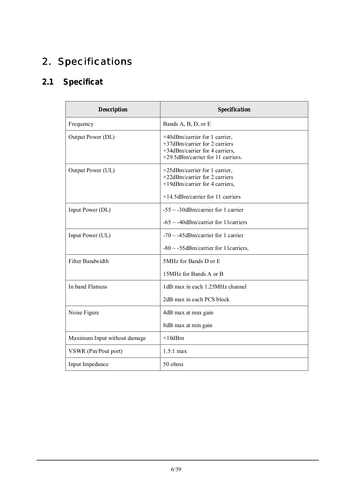
Description

Specification


Frequency

Bands A, B, D, or E


Output Power (DL)

+40dBm/carrier for 1 carrier,


+37dBm/carrier for 2 carriers


+34dBm/carrier for 4 carriers,


+29.5dBm/carrier for 11 carriers.


Output Power (UL)

+25dBm/carrier for 1 carrier,


+22dBm/carrier for 2 carriers


+19dBm/carrier for 4 carriers,


+14.5dBm/carrier for 11 carriers


Input Power (DL)

-55 ~ -30dBm/carrier for 1 carrier


-65 ~ -40dBm/carrier for 11carriers


Input Power (UL)

-70 ~ -45dBm/carrier for 1 carrier


-80 ~ -55dBm/carrier for 11carriers,


Filter Bandwidth

5MHz for Bands D or E


15MHz for Bands A or B


In band Flatness

1dB max in each 1.25MHz channel


2dB max in each PCS block


Noise Figure

4dB max at max gain


8dB max at min gain


Maximum Input without damage

+10dBm


VSWR (Pin/Pout port)

1.5:1 max


Input Impedance

50 ohms


6/39

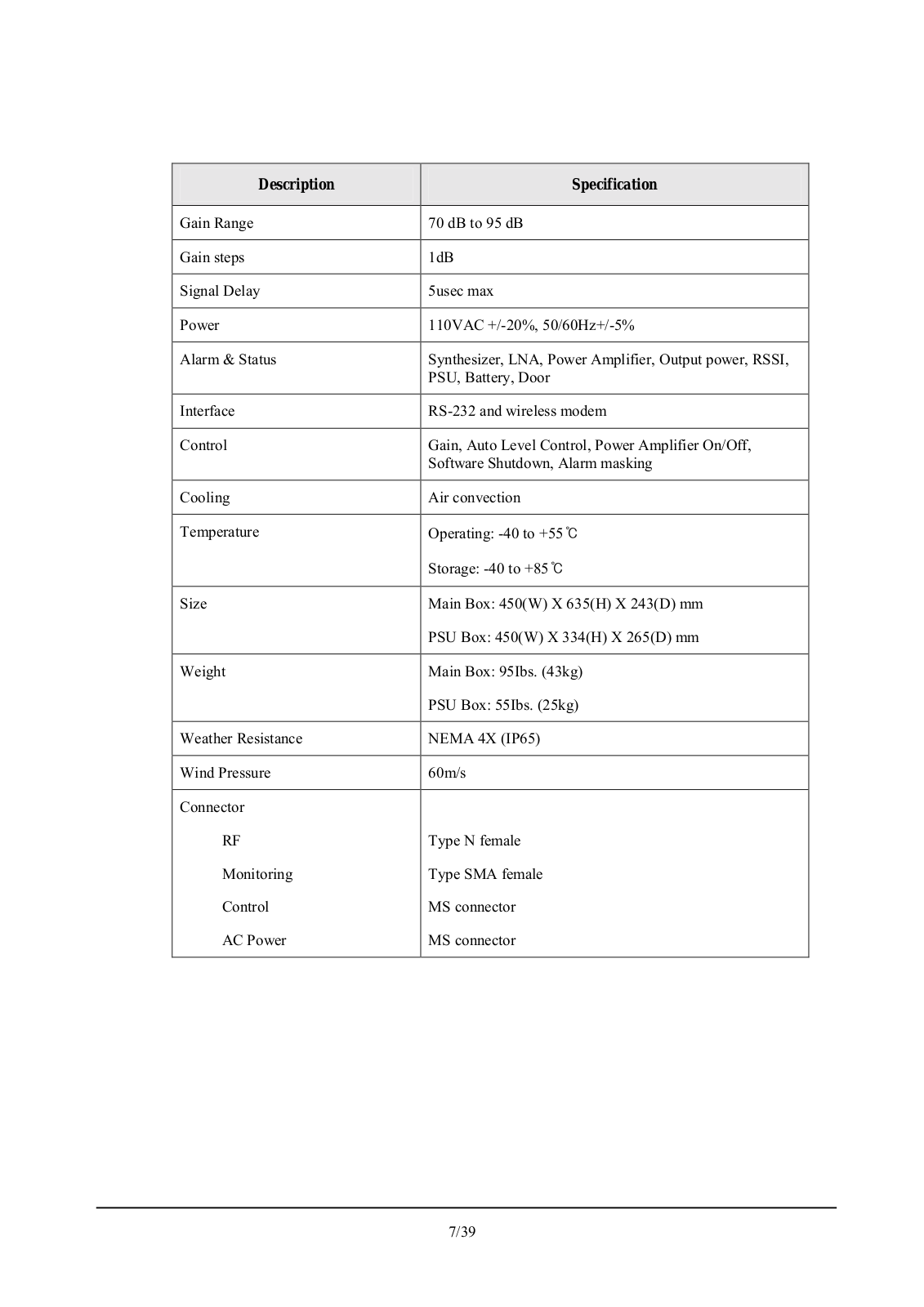
Description

Specification


Gain Range

70 dB to 95 dB


Gain steps

1dB


Signal Delay

5usec max


Power

110VAC +/-20%, 50/60Hz+/-5%


Alarm & Status

Synthesizer, LNA, Power Amplifier, Output power, RSSI,


PSU, Battery, Door


Interface

RS-232 and wireless modem


Control

Gain, Auto Level Control, Power Amplifier On/Off,


Software Shutdown, Alarm masking


Cooling

Air convection


Temperature

Operating: -40 to +55


Storage: -40 to +85


Size

Main Box: 450(W) X 635(H) X 243(D) mm


PSU Box: 450(W) X 334(H) X 265(D) mm


Weight

Main Box: 95Ibs. (43kg)


PSU Box: 55Ibs. (25kg)


Weather Resistance

NEMA 4X (IP65)


Wind Pressure

60m/s


Connector


RF

Type N female

Monitoring

Type SMA female

Control

MS connector

AC Power

MS connector


7/39

LG REAP10WHE User Manual

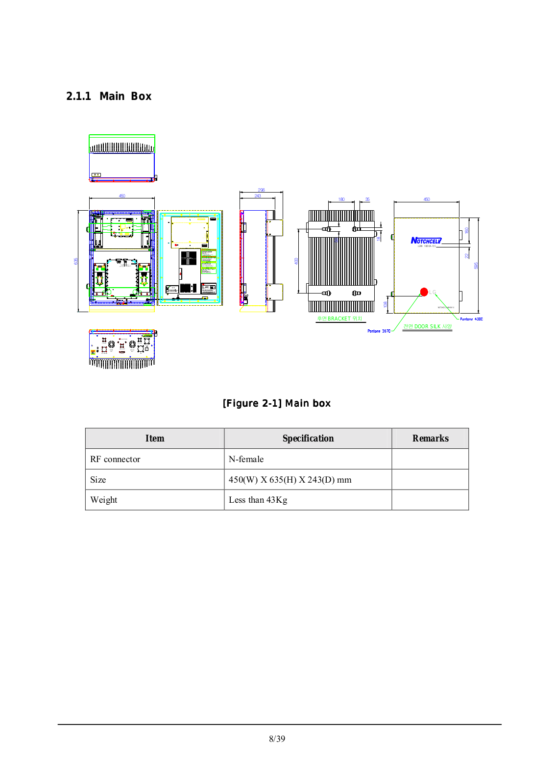
2.1.1 Main Box


LG


BRACKET

DOOR SILK


BLUE TOOTH


U/L MON


D/L MON


AC IN

DONOR

LOCAL OMT

SERVICE


ANT


ANT

EXT ALARM

ALARM

PSU

[Figure 2-1] Main box

Item

Specification

Remarks


RF connector

N-female


Size

450(W) X 635(H) X 243(D) mm


Weight

Less than 43Kg


8/39

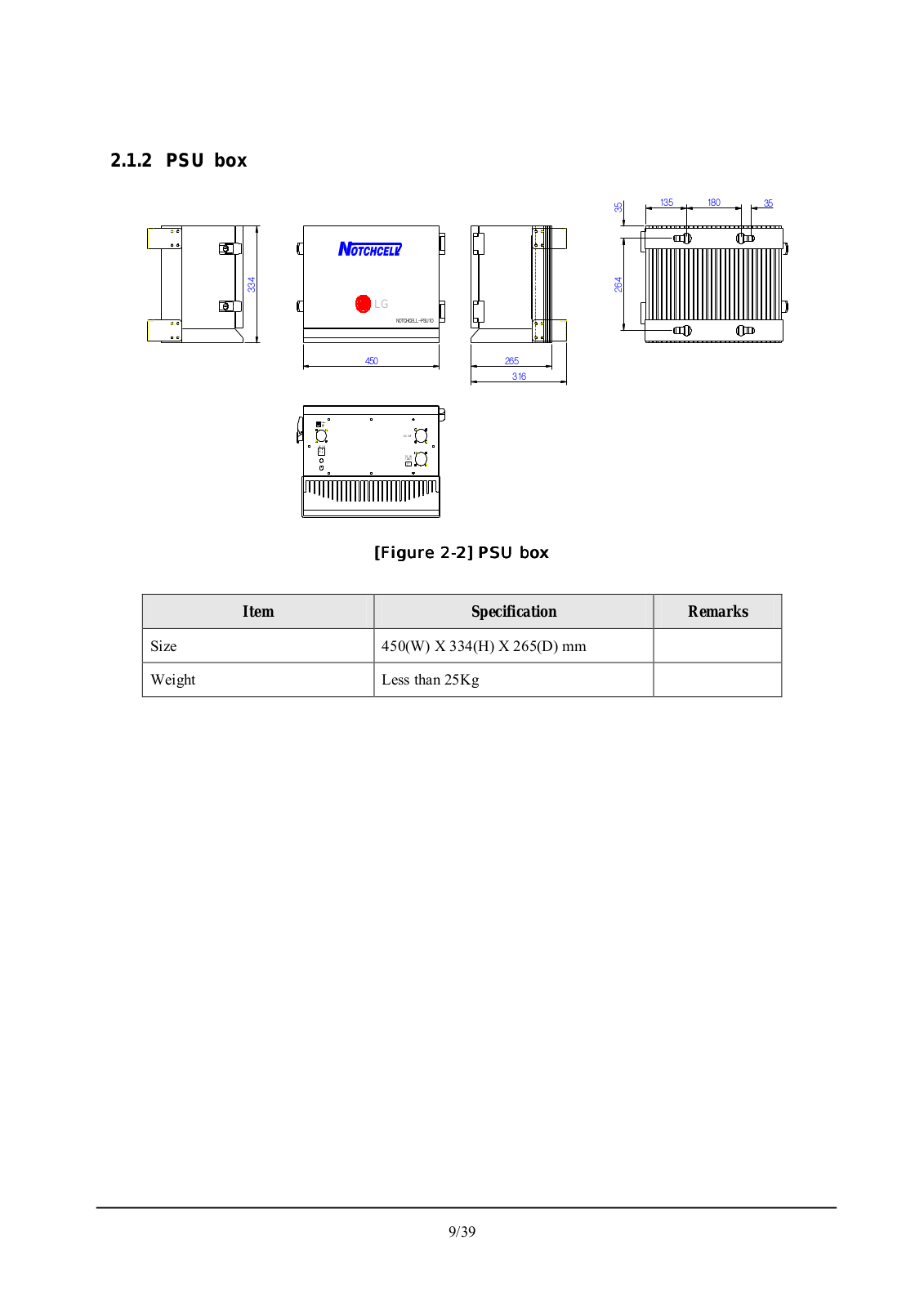
2.1.2 PSU box


LG


[Figure 2-2] PSU box

Item

Specification

Remarks


Size

450(W) X 334(H) X 265(D) mm


Weight

Less than 25Kg


9/39

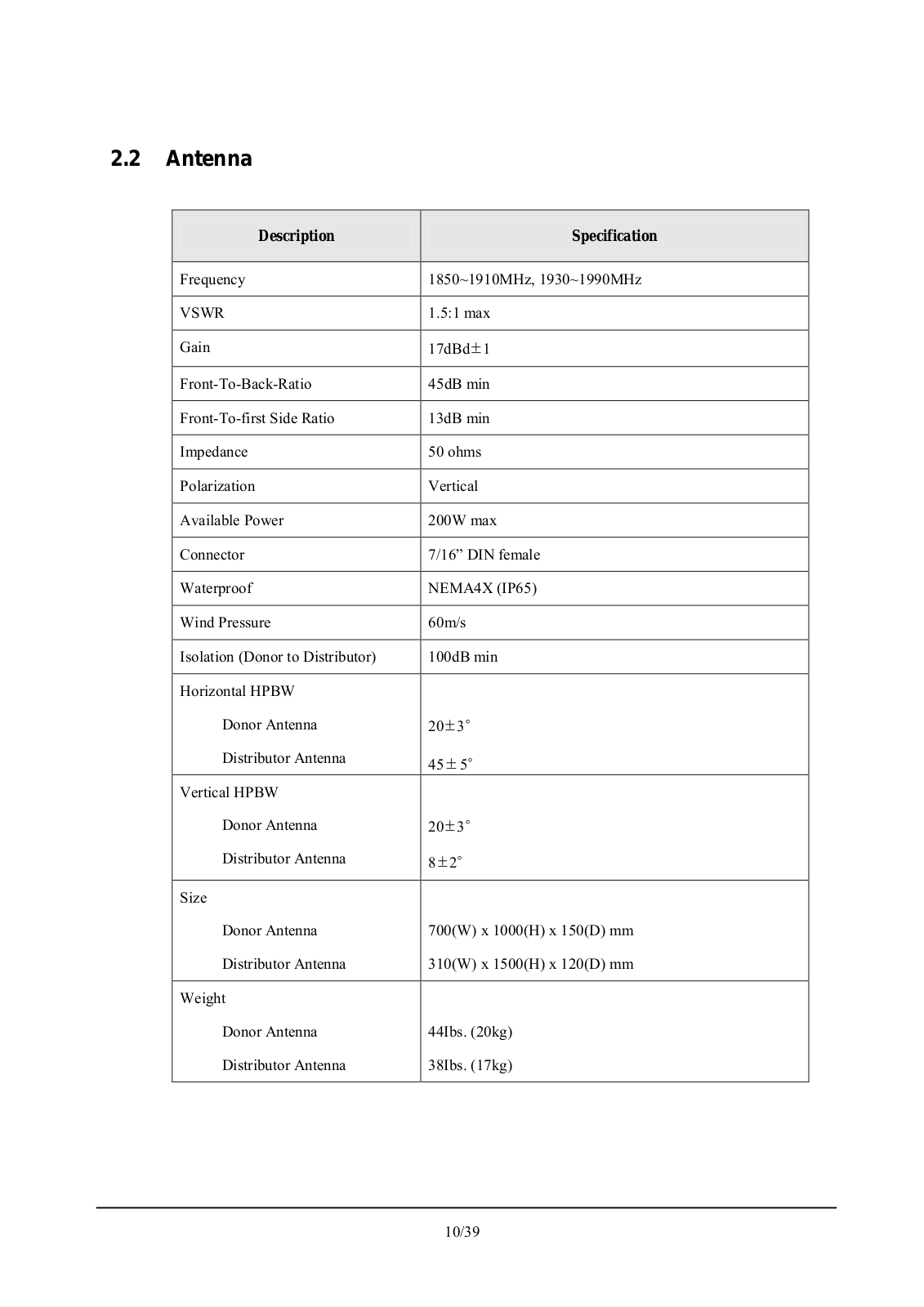
2.2 Antenna

Description

Specification


Frequency

1850~1910MHz, 1930~1990MHz


VSWR

1.5:1 max


Gain

17dBd 1


Front-To-Back-Ratio

45dB min


Front-To-first Side Ratio

13dB min


Impedance

50 ohms


Polarization

Vertical


Available Power

200W max


Connector

7/16” DIN female


Waterproof

NEMA4X (IP65)


Wind Pressure

60m/s


Isolation (Donor to Distributor)

100dB min


Horizontal HPBW


Donor Antenna

20 3


Distributor Antenna

45 5


Vertical HPBW


Donor Antenna

20 3


Distributor Antenna

8 2


Size


Donor Antenna

700(W) x 1000(H) x 150(D) mm


Distributor Antenna

310(W) x 1500(H) x 120(D) mm


Weight


Donor Antenna

44Ibs. (20kg)


Distributor Antenna

38Ibs. (17kg)


10/39

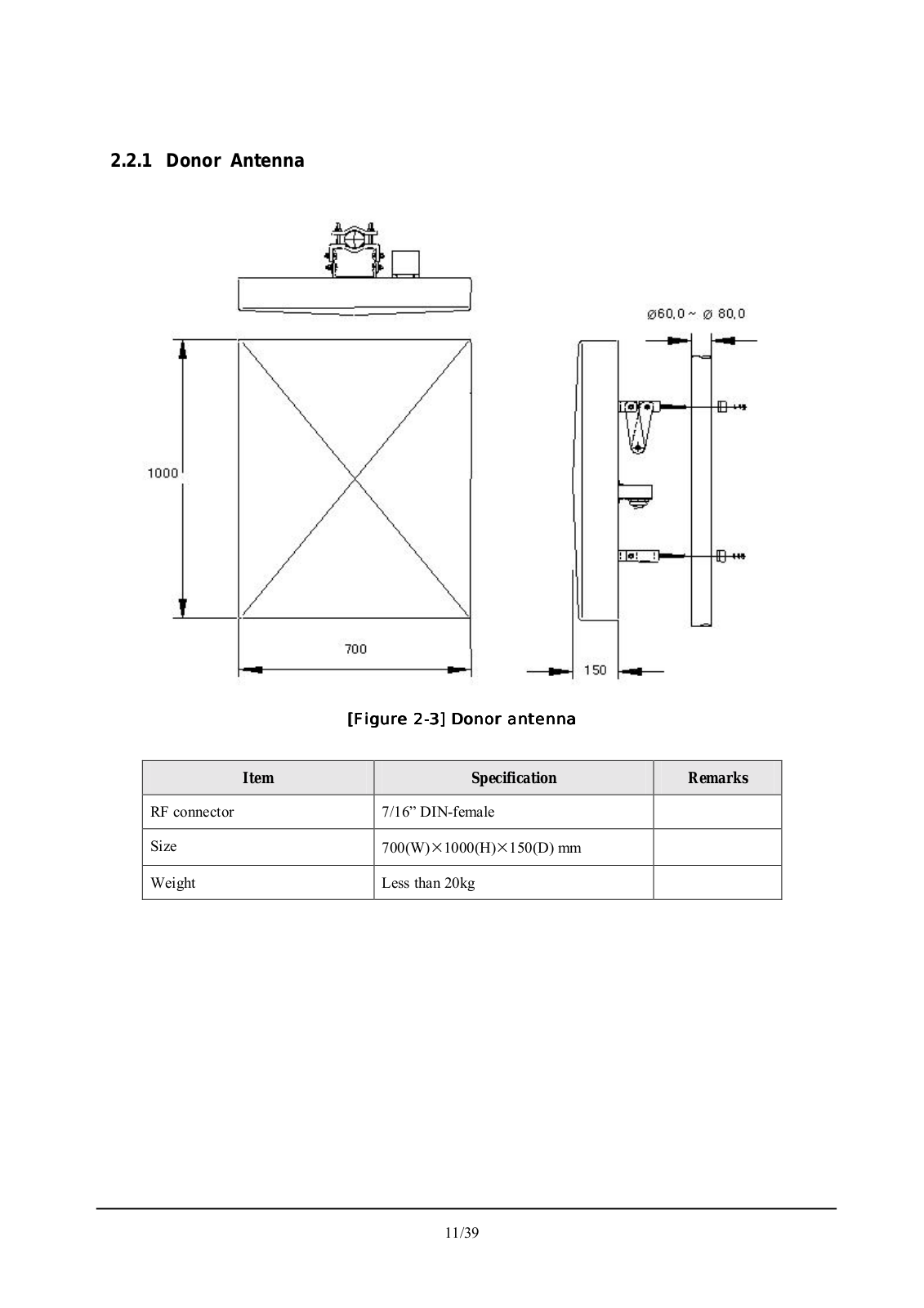
2.2.1 Donor Antenna

[Figure 2-3] Donor antenna

Item

Specification

Remarks


RF connector

7/16” DIN-female


Size

700(W) 1000(H) 150(D) mm


Weight

Less than 20kg


11/39

Loading...
+ 28 hidden pages