

Page 1
CUSTOMER : LGE
DATE : 2017.09.06.
SPECIFICATIONS FOR APPROVAL
PRODUCT NAME : BT(v4.2) + WLAN(802.11a/b/g/n/ac) 2.4G SISO/5G MIMO
MODEL NAME : RBHP-B213B
CUSTOMER P/N : EAT63433501
APPROVAL REMARK
APPENDIX
Designed Checked Approved
LG Innotek Co., Ltd.
DOCUMENT No.
PAGE 68
RBHP-B213B
(00)-0070
Page 2
TITLE : Specifications for approval (RBHP-B213B)
REV 1.6 (5 / 68)
(CUSTOMER P/NO : EAT63433501 )
1. Application
v
This specification is applied to LGInnotek Bluetooth (v4.2)and 2.4GHz SISO/5GHz MIMO
WLAN(802.11a/b/g/n/ac) Module RBHP-B213B which includes BCM88359
2. Quality
Quality should meet each condition which mentioned on this specification. However, the
items which are not mentioned on this specification follow the inspection agreements and
standards which are agreed with both companies.
3. Appearance and Characteristics
1) Appearance
Appearance should not be contaminated by harmful materials and should not have cracks
etc. Mechanical dimensions should meet the contents of clause 8.
2) Characteristics
Electrical characteristics should meet the contents of clause 10.
4. Application of Bluetooth v4.2 and 2.4GHz/5GHz WLAN(IEEE 802.11.a/b/g/n/ac)
1) Automotive
5. Maximum Rating
NO ITEM Rating UNIT
1 Operating Temperature Range -40 ~ +85 ℃
2 Storage Temperature Range -40 ~ +105 ℃
3 VBAT Voltage Range -0.5 ~ 6.0 V
4 VIO Voltage Range -0.5 ~ 3.9 V
5 VBAT Max. Current 700(@3.3V) mA
6 VIO Max. Current 50(@1.8V) mA
w
■ RBHP-B213B Module assures operating normally at -40 ~ +85 ℃.
1.2 2017. 05.23. Rev1.2 Released
R
1.3 2017. 06.27. Rev1.3 Released
1.4 2017. 07.14. Rev1.4 Released
E
1.5 2017. 08.10. Rev1.5 Released
V
1.6 2017. 09.06. Rev1.6 Released
LG Innotek Co., Ltd
APPD CHKD DSGD
RBHP-B213B
DOCUMENT NO.
6-3
(30) - 4021
Page 3
TITLE : Specifications for approval (RBHP-B213B)
(CUSTOMER P/NO : EAT63433501 )
6. Test
Electrical characteristics are tested for every products. However, if there are any
objection in judgments, it should be treated with agreements of companies.
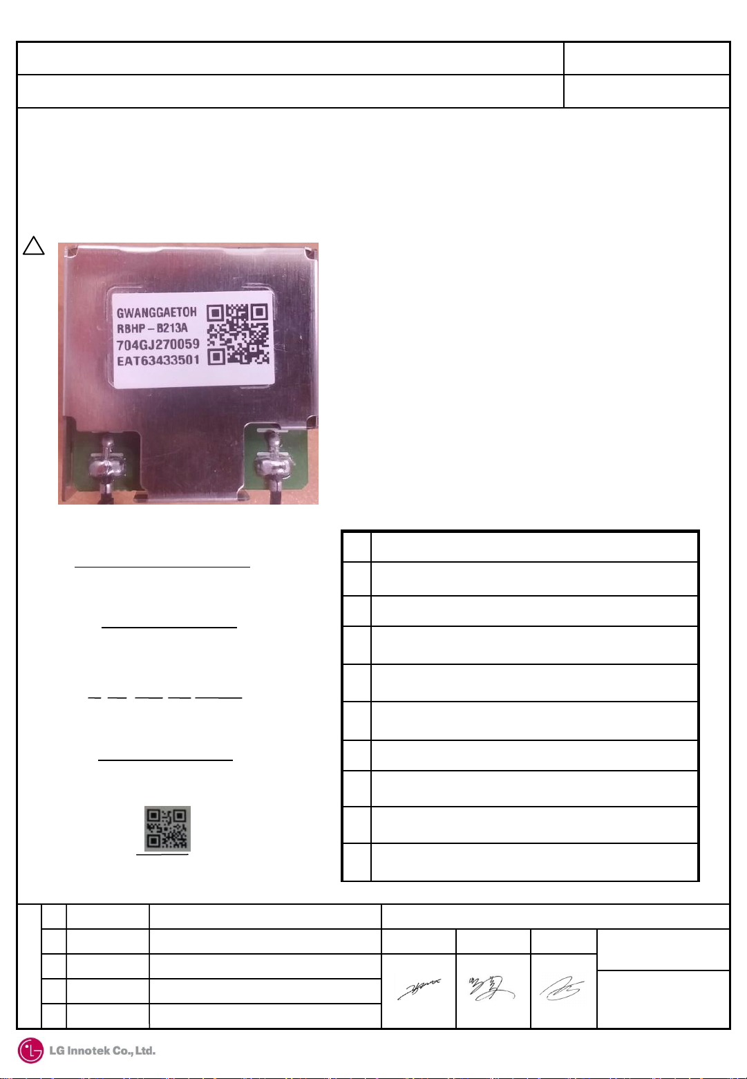
7. Labeling Information
p
REV 1.6 (6 / 68)
GWANGGAETOH
①
RBHP-B213B
②
7 04 GJ 27 0059
③
④ ⑤
⑥
EAT63433501
⑧
⑨
1.2 2017. 05.23. Rev1.2 Released
R
1.3 2017. 06.27. Rev1.3 Released
1.4 2017. 07.14. Rev1.4 Released
E
1.5 2017. 08.10. Rev1.5 Released
V
1.6 2017. 09.06. Rev1.6 Released
⑦
No. Index
① PRODUCT
② MODEL PART NO.
MANUFACTURED YEAR (0~9)
③
MANUFACTURED MONTH(1,2, …9, A,B,C)
④
⑤ GwangJu
⑥ MANUFACTURED DATE (1~31)
⑦ MANUFACTURED SERIAL NUMBER(0001~9999)
⑧ Customer P/N
QR CODE INFORMATION
⑨
: EAT63433501_704GJ270059
LG Innotek Co., Ltd
APPD CHKD DSGD
RBHP-B213B
DOCUMENT NO.
6-3
(30) - 4021
Page 4
TITLE : Specifications for approval (RBHP-B213B)
(CUSTOMER P/NO : EAT63433501 )
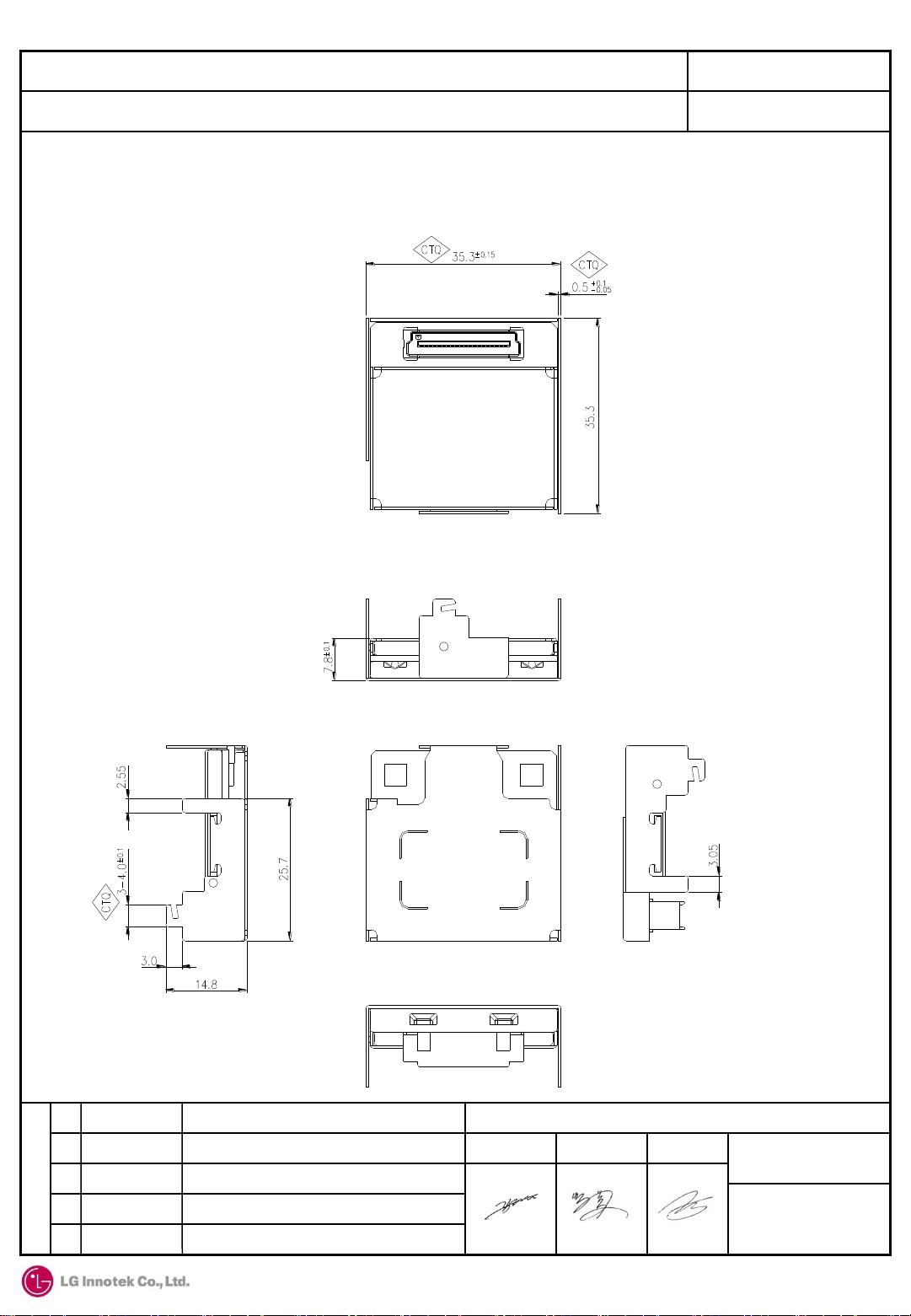
8. Mechanical Dimension
1) Dimension without Antenna Ass’y
REV 1.6 (7 / 68)
1.2 2017. 05.23. Rev1.2 Released
R
1.3 2017. 06.27. Rev1.3 Released
1.4 2017. 07.14. Rev1.4 Released
E
1.5 2017. 08.10. Rev1.5 Released
V
1.6 2017. 09.06. Rev1.6 Released
LG Innotek Co., Ltd
APPD CHKD DSGD
RBHP-B213B
DOCUMENT NO.
[Unit: mm]
6-3
(30) - 4021
Page 5

TITLE : Specifications for approval (RBHP-B213B)
(CUSTOMER P/NO : EAT63433501 )
8. Mechanical Dimension
2) Dimension with Antenna Ass’y
REV 1.6 (8 / 68)
1.2 2017. 05.23. Rev1.2 Released
R
1.3 2017. 06.27. Rev1.3 Released
1.4 2017. 07.14. Rev1.4 Released
E
1.5 2017. 08.10. Rev1.5 Released
V
1.6 2017. 09.06. Rev1.6 Released
LG Innotek Co., Ltd
APPD CHKD DSGD
RBHP-B213B
DOCUMENT NO.
[Unit: mm]
6-3
(30) - 4021
Page 6

TITLE : Specifications for approval (RBHP-B213B)
REV 1.6 (9 / 68)
(CUSTOMER P/NO : EAT63433501 )
9. General Features
9.1 BT(v4.2) + 2.4GHz/5GHz WLAN(IEEE 802.11a/b/g/n/ac) 2.4G SISO/5G MIMO
1) Features
• Operation Voltage is 3.3V/1.8V Dual Power Rail
• WiFi Single-stream up to 866 Mbps data rate
• Automotive Module
: All components are AEC-Q 100/200 qualified
• Support 2 Antenna port
: ANT0 : Bluetooth/5G WLAN, ANT1 : 2.4G/5G WLAN
• Integrated WLAN PA, RF Switch and LNA
• RoHS Compliant
• Size : 35.3 x 35.3 x 7.8 mm
3
• Support bandwidth : HT20 / HT40 / VHT80
• HOST Interface : PCIE/SDIO(WLAN), UART(BT), PCM(I2S)
• Package type : Connector type(B to B)
1.2 2017. 05.23. Rev1.2 Released
R
1.3 2017. 06.27. Rev1.3 Released
1.4 2017. 07.14. Rev1.4 Released
E
1.5 2017. 08.10. Rev1.5 Released
V
1.6 2017. 09.06. Rev1.6 Released
LG Innotek Co., Ltd
APPD CHKD DSGD
RBHP-B213B
DOCUMENT NO.
6-3
(30) - 4021
Page 7
TITLE : Specifications for approval (RBHP-B213B)
REV 1.6 (10 / 68)
(CUSTOMER P/NO : EAT63433501 )
9. General Features
9.2 Bluetooth(BT v4.2+EDR compliant)
1) Bluetooth Key Features
• Supports key features of upcoming Bluetooth standards
• Fully supports Bluetooth Core Specification version 4.2 + (Enhanced Data Rate)
EDR features:
-. Adaptive Frequency Hopping (AFH)
-. Quality of Service (QoS)
-. Extended Synchronous Connections (eSCO) – Voice Connections
-. Fast Connect (interlaced page and inquiry scans)
-. Secure simple Pairing (SSP)
-. Sniff Sub rating (SSR)
-. Encryption Pause Resume (EPR)
-. Extended Inquiry Response (EIR)
-. Link Supervision Timeout (LST)
• UART baud rates up to 4 Mbps
• Supports all Bluetooth 4.2 packet types
• Supports maximum Bluetooth data rates over HCI UART
• Multipoint operation with up to seven active slaves
-. Maximum of seven simultaneous active ACL links
-. Maximum of three simultaneous active SCO and eSCO connections with
scatternet support
• Narrowband and wideband packet loss concealment
• Scatternet operation with up to four active piconets with background scan and
support for scatter mode
• High-speed HCI UART transport support
• Channel quality driven data rate and packet type selection
• Standard Bluetooth test modes
• Extended radio and production test mode features
• Full support for power savings modes
-. Bluetooth clock request
-. Bluetooth standard sniff
-. Deep-sleep modes and software regulator shutdown
1.2 2017. 05.23. Rev1.2 Released
R
1.3 2017. 06.27. Rev1.3 Released
1.4 2017. 07.14. Rev1.4 Released
E
1.5 2017. 08.10. Rev1.5 Released
V
1.6 2017. 09.06. Rev1.6 Released
LG Innotek Co., Ltd
APPD CHKD DSGD
RBHP-B213B
DOCUMENT NO.
6-3
(30) - 4021
Page 8

TITLE : Specifications for approval (RBHP-B213B)
REV 1.6 (11 / 68)
(CUSTOMER P/NO : EAT63433501 )
9. General Features
9.3 WLAN
1) WLAN RF band & modulation Features
• Dual-band 2.4GHz and 5GHz 802.11 a/b/g/n/ac(802.11ac compliant)
• Up to 866Mbps data rate
• Supports 20, 40 and 80MHz channels with optional SGI(256 QAM modulation)
• Tx and Rx low-density parity check(LDPC)
• Supports IEEE 802.11ac/n beamforming
• Supports PCIe v3.0-compliant interface running at GEN1 speeds
• Supports two antennas with Bluetooth/5G WLAN and 2.4G/5G WLAN antenna
• Supports standard SDIO V3.0 (up to SDR104 mode at 208MHz, 4-bit and 1-bit)
• Backward compatibility with SDIO v2.0 host interface
• WPA and WPA2(Personal) support for powerful encryption and authentication
• AES and TKIP in hardware for faster data encryption and IEEE 802.11i
compatibility
• Reference WLAN subsystem provides Wi-Fi protected Setup(WPS)
2) WLAN MAC features
• Enhanced MAC for supporting IEEE 802.11ac features
• Transmission and reception of aggregated MPDUs(A-MPDU) for high
throughput(HT)
• Support for power management schemes, including WMM power-save multi-
poll(PSMP) and multiphase PSMP operation
• Support for immediate ACK and block-ACK policies
• Inter-frame space timing support, including RIFS
• Back-off counters in hardware for supporting multiple priorities as specified in the
WMM specification
• Timing synchronization function(TSF), network allocation vector(NAV)
maintenance, and target beacon transmission time(TBTT) generation in hardware
• Hardware offload for AES-CCMP, legacy WPA TKIP, legacy WEP ciphers, WAPI,
and support for key management
• Programmable independent basic service set(IBSS) or infrastructure basic service
set functionality
1.2 2017. 05.23. Rev1.2 Released
R
1.3 2017. 06.27. Rev1.3 Released
1.4 2017. 07.14. Rev1.4 Released
E
1.5 2017. 08.10. Rev1.5 Released
V
1.6 2017. 09.06. Rev1.6 Released
LG Innotek Co., Ltd
APPD CHKD DSGD
RBHP-B213B
DOCUMENT NO.
6-3
(30) - 4021
Page 9
TITLE : Specifications for approval (RBHP-B213B)
REV 1.6 (12 / 68)
(CUSTOMER P/NO : EAT63433501 )
9. General Features
9.3 WLAN
3) WLAN PHY features
• Programmable data rates from MCS0-9 in 20MHz, 40MHz, and 80MHz channels,
as specified in IEEE 802.11ac
• Improved performance with channel smoothing and spur canceller support
• Supports Optional short GI and Green field modes in Tx and Rx
• Tx and Rx LDPC for improved range and power efficiency
• Beamforming support
• Supports IEEE 802.11h/k for worldwide operation
• Advanced algorithms for low power, enhanced sensitivity, range, and reliability
• IEEE 802.11a, 11b, 11g, 11n, 11ac single stream PHY standards
• Designed to meet FCC and other worldwide regulatory requirements
9.4 JEDEC MSL (Moisture Sensitivity Level) Test
• MSL 3 Level (Floor Life Time : 168Hrs. / Condition : ≤30℃, 60% RH)
• Standard : IPC / JEDEC J-STD-020C
Bake
Soak
Reflow
24Hrs. / 125℃
40Hrs. / 60℃, 60% RH
3 times / 240℃
1.2 2017. 05.23. Rev1.2 Released
R
1.3 2017. 06.27. Rev1.3 Released
1.4 2017. 07.14. Rev1.4 Released
E
1.5 2017. 08.10. Rev1.5 Released
V
1.6 2017. 09.06. Rev1.6 Released
LG Innotek Co., Ltd
APPD CHKD DSGD
RBHP-B213B
DOCUMENT NO.
6-3
(30) - 4021
Page 10
TITLE : Specifications for approval (RBHP-B213B)
REV 1.6 (30 / 68)
(CUSTOMER P/NO : EAT63433501 )
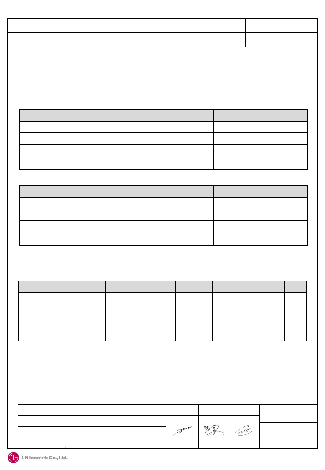
10. Electrical Specification
10.3 I/O characteristics
1) SDIO Interface I/O pins and PCIe out of band signals(PERST_N/PME_L/CLKREQ_N)
*VIO_SD= 1.8V
Item Symbol Min Typ Max Unit
Input high voltage VIH 1.27 - - V
Input low voltage VIL - - 0.58 V
Output high voltage@2mA
Output low voltage@2mA
*VIO_SD = 3.3V
Item Symbol Min Typ Max Unit
Input high voltage VIH 0.625xVIO - - V
Input low voltage VIL - - 0.25xVIO V
Output high voltage@2mA
Output low voltage@2mA
VOH
VOL
VOH
VOL
1.40 - - V
- - 0.45 V
0.75xVIO - - V
- - 1.25xVIO V
2) Other Digital I/O Pins(UART/PCM/WAKE/REG_ON/STRAP and GPIOs)
*VIO = 1.8V
Item Symbol Min Typ Max Unit
Input high voltage VIH 0.625xVIO - VIO+0.1 V
Input low voltage VIL - - 0.35xVIO V
Output high voltage@2mA
VOH
0.45xVIO - - V
Output low voltage@2mA
1.2 2017. 05.23. Rev1.2 Released
R
1.3 2017. 06.27. Rev1.3 Released
1.4 2017. 07.14. Rev1.4 Released
E
1.5 2017. 08.10. Rev1.5 Released
V
1.6 2017. 09.06. Rev1.6 Released
VOL
- - 0.45 V
LG Innotek Co., Ltd
APPD CHKD DSGD
RBHP-B213B
DOCUMENT NO.
6-3
(30) - 4021
Page 11
TITLE : Specifications for approval (RBHP-B213B)
REV 1.6 (31 / 68)
(CUSTOMER P/NO : EAT63433501 )
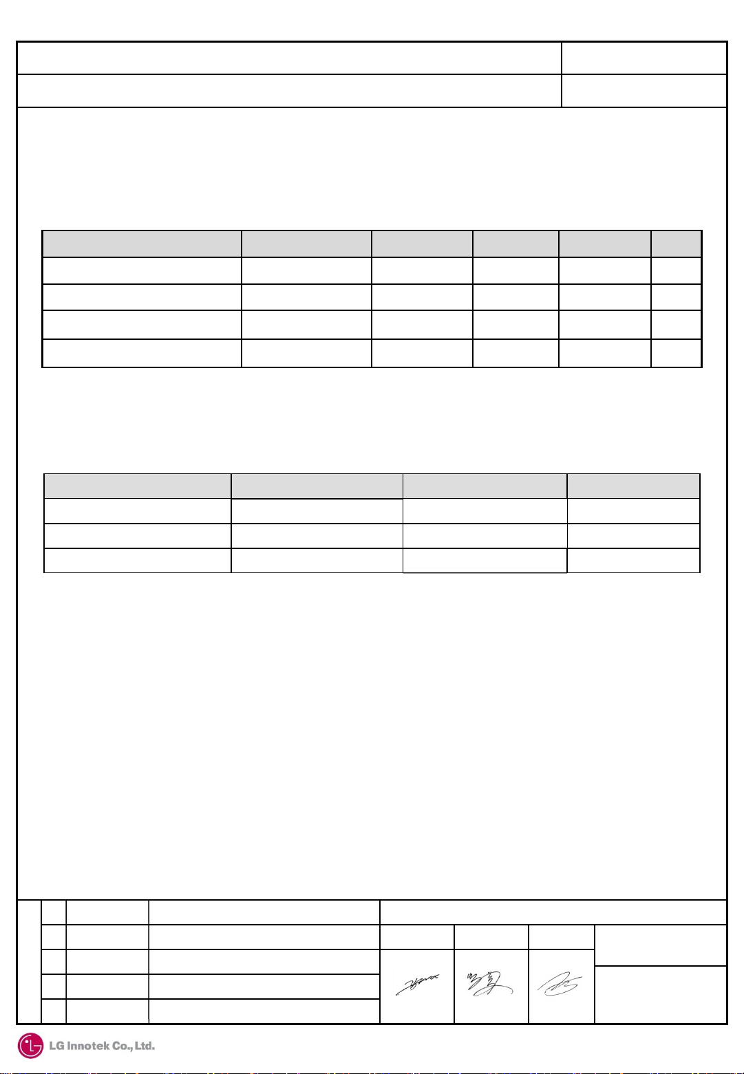
10. Electrical Specification
10.3 I/O characteristics
*VIO = 3.3V
Item Symbol Min Typ Max Unit
Input high voltage VIH 2.00 - VIO+0.1 V
Input low voltage VIL - - 0.8 V
Output high voltage@2mA
Output low voltage@2mA
VOH
VOL
VIO-0.4 - - V
- - 0.4 V
3) WLAN host interface strap selection
- PCIE_EN, SDIO_DIS, SDIO_PAD
PCIE_EN Mode
High PCIe
Low 1.8V SDIO Low
Low
SDIO_DIS
High
Low
SDIO_PAD
High
High
low
3.3V SDIO
4) Sequencing of reset and regulator control signals
- Description of control signals
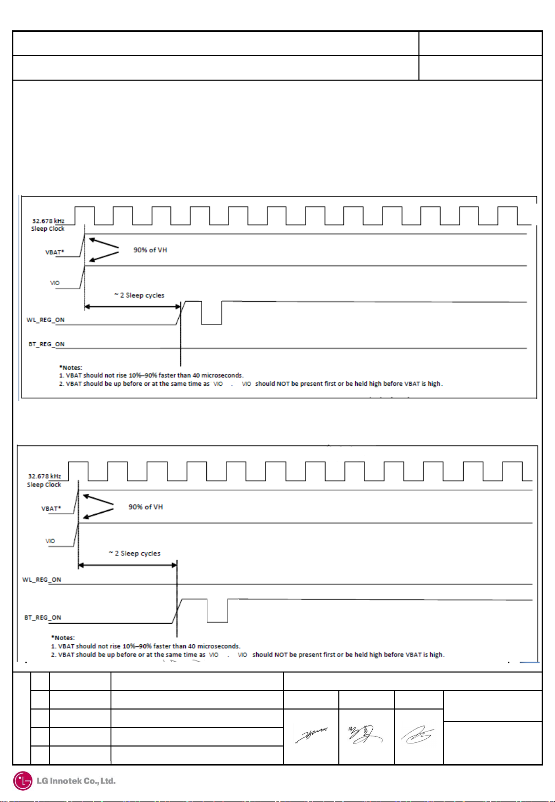
*WL_REG_ON
: Used by the PMU to power up the WLAN section. It is also OR-gated with the BT_REG_ON input to
control the internal BCM88359 regulators. When this pin is high, the regulators are enabled and the
WLAN section is out of reset. When this pin is low, the WLAN section is in reset. If both the
BT_REG_ON and WL_REG_ON pins are low, the regulators are disabled
*BT_REG_ON
: Used by the PMU(OR-gated with the WL_REG_ON)to power up the internal BCM88359 regulators. If
both the BT_REG_ON and WL_REG_ON pins are low, the regulators are disabled. When this pin is low
and WL_REG_ON is high, the BT section is in reset
1.2 2017. 05.23. Rev1.2 Released
R
1.3 2017. 06.27. Rev1.3 Released
1.4 2017. 07.14. Rev1.4 Released
E
1.5 2017. 08.10. Rev1.5 Released
V
1.6 2017. 09.06. Rev1.6 Released
LG Innotek Co., Ltd
APPD CHKD DSGD
RBHP-B213B
DOCUMENT NO.
6-3
(30) - 4021
Page 12

TITLE : Specifications for approval (RBHP-B213B)
(CUSTOMER P/NO : EAT63433501 )
10. Electrical Specification
10.3 I/O characteristics
- Control signal timing diagrams
*WLAN =ON, Bluetooth = ON
REV 1.6 (32 / 68)
*WLAN =OFF, Bluetooth = OFF
1.2 2017. 05.23. Rev1.2 Released
R
1.3 2017. 06.27. Rev1.3 Released
1.4 2017. 07.14. Rev1.4 Released
E
1.5 2017. 08.10. Rev1.5 Released
V
1.6 2017. 09.06. Rev1.6 Released
LG Innotek Co., Ltd
APPD CHKD DSGD
RBHP-B213B
DOCUMENT NO.
6-3
(30) - 4021
Page 13
TITLE : Specifications for approval (RBHP-B213B)
(CUSTOMER P/NO : EAT63433501 )
10. Electrical Specification
10.3 I/O characteristics
- Control signal timing diagrams
*WLAN =ON, Bluetooth = OFF
REV 1.6 (33 / 68)
*WLAN =OFF, Bluetooth = ON
1.2 2017. 05.23. Rev1.2 Released
R
1.3 2017. 06.27. Rev1.3 Released
1.4 2017. 07.14. Rev1.4 Released
E
1.5 2017. 08.10. Rev1.5 Released
V
1.6 2017. 09.06. Rev1.6 Released
LG Innotek Co., Ltd
APPD CHKD DSGD
RBHP-B213B
DOCUMENT NO.
6-3
(30) - 4021
Page 14
TITLE : Specifications for approval (RBHP-B213B)
(CUSTOMER P/NO : EAT63433501 )
10. Electrical Specification
10.3 I/O characteristics
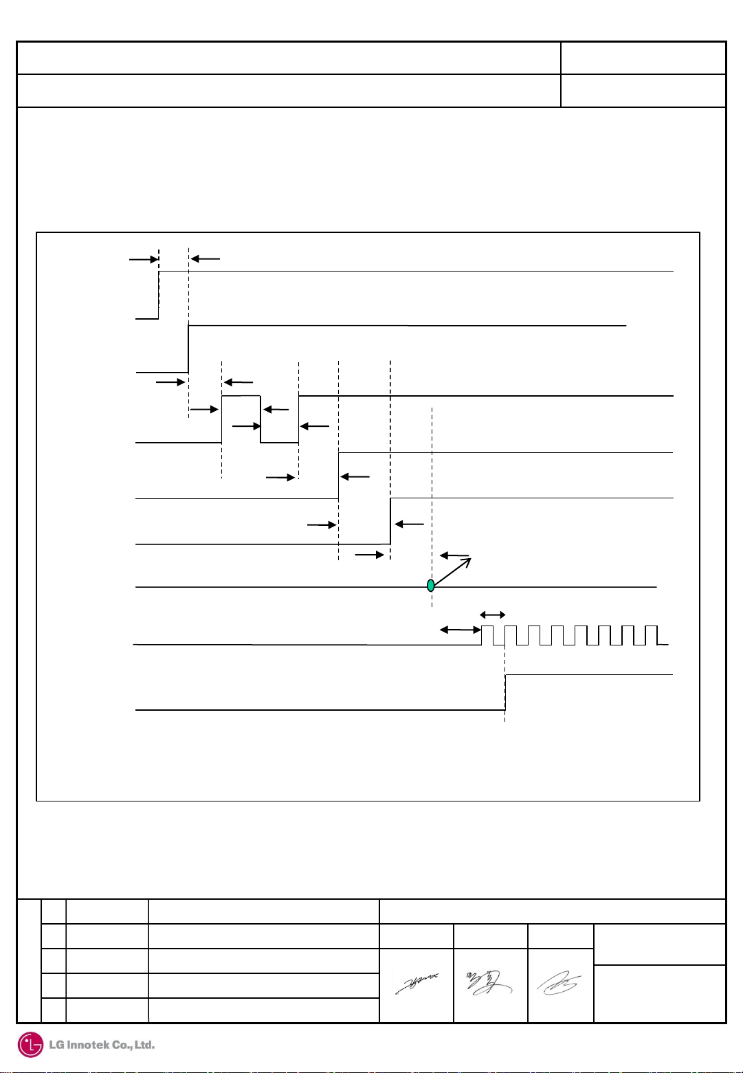
- Boot-Up Sequence and Reset timing
REV 1.6 (34 / 68)
VBAT
VIO
WL_REG_ON
/BT_REG_ON
VDDC
(on-chip PMU)
Internal POR
(Power on Reset)
Internal
Reference
Clock
<0ms
<70us
<200ms
<200ms
< 950us
< 104ms
< 4ms
3.3V
After a fixed delay following internal POR
and REG_ON going high, Module
responds to host(address0x14) reads
27ns
8ms
Boot ROM execution starts and
firmware download begins
(UART and SDIO command start)
1.2 2017. 05.23. Rev1.2 Released
R
1.3 2017. 06.27. Rev1.3 Released
1.4 2017. 07.14. Rev1.4 Released
E
1.5 2017. 08.10. Rev1.5 Released
V
1.6 2017. 09.06. Rev1.6 Released
LG Innotek Co., Ltd
APPD CHKD DSGD
RBHP-B213B
DOCUMENT NO.
6-3
(30) - 4021
Page 15

TITLE : Specifications for approval (RBHP-B213B)
(CUSTOMER P/NO : EAT63433501 )
10. Electrical Specification
10.3 I/O characteristics
r
- PCIe Power-on Timing
*Timing Parameter WL_REG_ON)Perst# Deassertion – First Config Access)
REV 1.6 (35 / 68)
1.2 2017. 05.23. Rev1.2 Released
R
1.3 2017. 06.27. Rev1.3 Released
1.4 2017. 07.14. Rev1.4 Released
E
1.5 2017. 08.10. Rev1.5 Released
V
1.6 2017. 09.06. Rev1.6 Released
LG Innotek Co., Ltd
APPD CHKD DSGD
RBHP-B213B
DOCUMENT NO.
6-3
(30) - 4021
Page 16

TITLE : Specifications for approval (RBHP-B213B)
REV 1.6 (36 / 68)
(CUSTOMER P/NO : EAT63433501 )
10. Electrical Specification
10.3 I/O characteristics
5) UART characteristics
-. UART physical interface is a standard, 4-wire interface(Rx, Tx, RTS, CTS) with
adjustable baud rates from 9600 bps to 4Mbps. Normally the UART baud rate is set
by a configuration record downloaded after reset or by automatic baud rate detection.
LGIT Module supports HCI 3-wire transport(UART H5)
-. UART bus timing specifications
Item Min Typ Max Unit
Delay time, UART_CTS_N low to UART_TXD valid - - 1.5 Bit periods
Setup time, UART_CTS_N high before midpoint of stop bit - - 0.5 Bit periods
Delay time, midpoint of stop bit to UART RTS_N high - - 0.5 Bit periods
Baud rates range(default rate : 115200bps) 9600 - 4M bps
-. UART bus timing
1.2 2017. 05.23. Rev1.2 Released
R
1.3 2017. 06.27. Rev1.3 Released
1.4 2017. 07.14. Rev1.4 Released
E
1.5 2017. 08.10. Rev1.5 Released
V
1.6 2017. 09.06. Rev1.6 Released
LG Innotek Co., Ltd
APPD CHKD DSGD
RBHP-B213B
DOCUMENT NO.
6-3
(30) - 4021
Page 17

TITLE : Specifications for approval (RBHP-B213B)
REV 1.6 (37 / 68)
(CUSTOMER P/NO : EAT63433501 )
10. Electrical Specification
10.3 I/O characteristics
6) PCM characteristics
-. LGIT Module PCM interface can connect to linear PCM codec devices in master or slave
mode. In master mode, the device generates the PCM_CLK and PCM_SYNC signals. In slave
mode, these signals are provided by another master on the PCM interfaces as inputs to the
devices
-. Short frame sync, master mode timing diagram
-. Short frame sync, master mode interface timing specifications
Item Min Typ Max Unit
PCM bit clock frequency - - 12 MHz
PCM bit clock LOW 41 - - ns
PCM bit clock HIGH 41 - - ns
PCM_SYNC delay 0 - 25 ns
PCM_OUT delay - - 25 ns
PCM_IN setup 8 - - ns
PCM_IN hold 8 - - ns
Delay from rising edge of PCM_BCLK during last bit period to
PCM_OUT becoming high impedance
1.2 2017. 05.23. Rev1.2 Released
R
1.3 2017. 06.27. Rev1.3 Released
1.4 2017. 07.14. Rev1.4 Released
E
1.5 2017. 08.10. Rev1.5 Released
V
1.6 2017. 09.06. Rev1.6 Released
- - 25 ns
LG Innotek Co., Ltd
APPD CHKD DSGD
RBHP-B213B
DOCUMENT NO.
6-3
(30) - 4021
Page 18

TITLE : Specifications for approval (RBHP-B213B)
(CUSTOMER P/NO : EAT63433501 )
10. Electrical Specification
10.3 I/O characteristics
6) PCM characteristics
-. Short frame sync, slave mode timing diagram
REV 1.6 (38 / 68)
-. Short frame sync, slave mode interface timing specifications
Item Min Typ Max Unit
PCM bit clock frequency - - 12 MHz
PCM bit clock LOW 41 - - ns
PCM bit clock HIGH 41 - - ns
PCM_SYNC setup 8 - - ns
PCM_SYNC hold 8 - - ns
PCM_OUT delay - - 25 ns
PCM_IN setup 8 - - ns
PCM_IN hold 8 - - ns
Delay from rising edge of PCM_CLK during last bit period to
PCM_OUT becoming high impedance
1.2 2017. 05.23. Rev1.2 Released
R
1.3 2017. 06.27. Rev1.3 Released
1.4 2017. 07.14. Rev1.4 Released
E
1.5 2017. 08.10. Rev1.5 Released
V
1.6 2017. 09.06. Rev1.6 Released
0 - 25 ns
LG Innotek Co., Ltd
APPD CHKD DSGD
RBHP-B213B
DOCUMENT NO.
6-3
(30) - 4021
Page 19

TITLE : Specifications for approval (RBHP-B213B)
(CUSTOMER P/NO : EAT63433501 )
10. Electrical Specification
10.3 I/O characteristics
6) PCM characteristics
-. Long frame sync, master mode timing diagram
REV 1.6 (39 / 68)
-. Long frame sync, master mode interface timing specifications
Item Min Typ Max Unit
PCM bit clock frequency - - 12 MHz
PCM bit clock LOW 41 - - ns
PCM bit clock HIGH 41 - - ns
PCM_SYNC delay 0 - 25 ns
PCM_OUT delay 0 - 25 ns
PCM_IN setup 8 - - ns
PCM_IN hold 8 - - ns
Delay from rising edge of PCM_BCLK during last bit period to
PCM_OUT becoming high impedance
1.2 2017. 05.23. Rev1.2 Released
R
1.3 2017. 06.27. Rev1.3 Released
1.4 2017. 07.14. Rev1.4 Released
E
1.5 2017. 08.10. Rev1.5 Released
V
1.6 2017. 09.06. Rev1.6 Released
0 - 25 ns
LG Innotek Co., Ltd
APPD CHKD DSGD
RBHP-B213B
DOCUMENT NO.
6-3
(30) - 4021
Page 20

TITLE : Specifications for approval (RBHP-B213B)
(CUSTOMER P/NO : EAT63433501 )
10. Electrical Specification
10.3 I/O characteristics
6) PCM characteristics
-. Long frame sync, slave mode timing diagram
REV 1.6 (40 / 68)
-. Long frame sync, slave mode interface timing specifications
Item Min Typ Max Unit
PCM bit clock frequency - - 12 MHz
PCM bit clock LOW 41 - - ns
PCM bit clock HIGH 41 - - ns
PCM_SYNC setup 8 - - ns
PCM_SYNC hold 8 - - ns
PCM_OUT Delay 0 - 25 ns
PCM_IN setup 8 - - ns
PCM_IN hold 8 - - ns
Delay from falling edge of PCM_BCLK or PCM_SYNC
during last bit period to PCM_OUT becoming high impedance
1.2 2017. 05.23. Rev1.2 Released
R
1.3 2017. 06.27. Rev1.3 Released
1.4 2017. 07.14. Rev1.4 Released
E
1.5 2017. 08.10. Rev1.5 Released
V
1.6 2017. 09.06. Rev1.6 Released
0 - 25 ns
LG Innotek Co., Ltd
APPD CHKD DSGD
RBHP-B213B
DOCUMENT NO.
6-3
(30) - 4021
Page 21

TITLE : Specifications for approval (RBHP-B213B)
(CUSTOMER P/NO : EAT63433501 )
10. Electrical Specification
10.3 I/O characteristics
7) SDIO characteristics
-. RBHP-B213B support up to SDIO 3.0 specification
· DS : Default speed(DS) up to 25MHz(3.3V signaling)
· SDR12 : SDR up to 25MHz(1.8V signaling)
· SDR25 : SDR up to 50MHz(1.8V signaling)
· SDR50 : SDR up to 100MHz(1.8V signaling)
· SDR104 : SDR up to 208MHz(1.8V signaling)
· DDR50 : DDR up to 50MHz(1.8V signaling)
REV 1.6 (41 / 68)
-. SDIO default mode timing(min.Vih = 0.7 X VIO, max.Vil = 0.2 x VIO)
1.2 2017. 05.23. Rev1.2 Released
R
1.3 2017. 06.27. Rev1.3 Released
1.4 2017. 07.14. Rev1.4 Released
E
1.5 2017. 08.10. Rev1.5 Released
V
1.6 2017. 09.06. Rev1.6 Released
LG Innotek Co., Ltd
APPD CHKD DSGD
RBHP-B213B
DOCUMENT NO.
6-3
(30) - 4021
Page 22

TITLE : Specifications for approval (RBHP-B213B)
REV 1.6 (42 / 68)
(CUSTOMER P/NO : EAT63433501 )
10. Electrical Specification
10.3 I/O characteristics
-. SDIO default mode bus timing parameters
Item Symbol Min Typ Max Unit
SDIO CLK
Freq.(data transfer mode) fPP 0 - 25 MHz
Freq.(identification mode) fOD 0 400 KHz
Clock low time
Clock high time
Clock rise time
Clock low time
Input : CMD, DAT(referenced to CLK)
Input setup time
Input hold time
Output : CMD, DAT(referenced to CLK)
Output delay time-data transfer mode
Output delay time-data identification
mode
tWL
tWH
tTLH
tTHL
tISU
tIH
tODLY
tODLY
10 - - ns
10 - - ns
- - 10 ns
- - 10 ns
5 - - ns
5 - - ns
0 - 14 ns
0 - 50 ns
1.2 2017. 05.23. Rev1.2 Released
R
1.3 2017. 06.27. Rev1.3 Released
1.4 2017. 07.14. Rev1.4 Released
E
1.5 2017. 08.10. Rev1.5 Released
V
1.6 2017. 09.06. Rev1.6 Released
LG Innotek Co., Ltd
APPD CHKD DSGD
RBHP-B213B
DOCUMENT NO.
6-3
(30) - 4021
Page 23

TITLE : Specifications for approval (RBHP-B213B)
REV 1.6 (43 / 68)
(CUSTOMER P/NO : EAT63433501 )
10. Electrical Specification
10.3 I/O characteristics
-. SDIO high speed mode bus timing(min.Vih = 0.7 X VIO, max.Vil = 0.2 x VIO)
-. SDIO high speed mode bus timing parameters
Item Symbol Min Typ Max Unit
SDIO CLK
Freq.(data transfer mode) fPP 0 - 50 MHz
Freq.(identification mode) fOD 0 - 400 KHz
Clock low time
Clock high time
Clock rise time
Clock low time
1.2 2017. 05.23. Rev1.2 Released
R
1.3 2017. 06.27. Rev1.3 Released
1.4 2017. 07.14. Rev1.4 Released
E
1.5 2017. 08.10. Rev1.5 Released
V
1.6 2017. 09.06. Rev1.6 Released
tWL
tWH
tTLH
tTHL
7 - - ns
7 - - ns
- - 3 ns
- - 3 ns
LG Innotek Co., Ltd
APPD CHKD DSGD
RBHP-B213B
DOCUMENT NO.
6-3
(30) - 4021
Page 24

TITLE : Specifications for approval (RBHP-B213B)
(CUSTOMER P/NO : EAT63433501 )
10. Electrical Specification
10.3 I/O characteristics
Item Symbol Min Typ Max Unit
Input : CMD, DAT(referenced to CLK)
REV 1.6 (44 / 68)
Input setup time
Input hold time
Output : CMD, DAT(referenced to CLK)
Output delay time-data transfer mode
Output delay time-data identification
mode
Total system capacitance(each line)
-. SDIO SDR mode clock timing
tISU
tIH
tODLY
tODLY
CL
6 - - ns
2 - - ns
- - 14 ns
2.5 - - ns
- - 40 pF
Item Symbol Min Max Unit Comments
- t
-
Clock duty
1.2 2017. 05.23. Rev1.2 Released
R
1.3 2017. 06.27. Rev1.3 Released
1.4 2017. 07.14. Rev1.4 Released
E
1.5 2017. 08.10. Rev1.5 Released
V
1.6 2017. 09.06. Rev1.6 Released
CLK
tCR, t
CF
-
40 50 ns SDR12 mode
20 400 ns SDR25 mode
10 - ns SDR50 mode
4.8 - ns SDR104 mode
tCR, tCF < 2.0ns(max)@100MHz
-
30 70 % -
X t
0.2
CLK
ns
tCR, tCF < 0.96ns(max)@208MHz
C
C
CARD
CARD
= 10pF
= 10pF
LG Innotek Co., Ltd
APPD CHKD DSGD
RBHP-B213B
DOCUMENT NO.
6-3
(30) - 4021
Page 25

TITLE : Specifications for approval (RBHP-B213B)
(CUSTOMER P/NO : EAT63433501 )
10. Electrical Specification
10.3 I/O characteristics
-. SDIO SDR mode Device input timing
REV 1.6 (45 / 68)
Item Symbol Min Max Unit Comments
SDR104
Mode
SDR50
Mode
t
IS
t
IH
t
IS
t
IH
1.4 - ns C
0.8 - ns C
3 - ns C
0.8 - ns C
= 10pF, VCT=0.975V
CARD
= 5pF, VCT=0.975V
CARD
= 10pF, VCT=0.975V
CARD
= 10pF, VCT=0.975V
CARD
1.2 2017. 05.23. Rev1.2 Released
R
1.3 2017. 06.27. Rev1.3 Released
1.4 2017. 07.14. Rev1.4 Released
E
1.5 2017. 08.10. Rev1.5 Released
V
1.6 2017. 09.06. Rev1.6 Released
LG Innotek Co., Ltd
APPD CHKD DSGD
RBHP-B213B
DOCUMENT NO.
6-3
(30) - 4021
Page 26

TITLE : Specifications for approval (RBHP-B213B)
(CUSTOMER P/NO : EAT63433501 )
10. Electrical Specification
10.3 I/O characteristics
-. SDIO SDR mode Device output timing(SDR modes up to 100MHz)
REV 1.6 (46 / 68)
Symbol Min Max Unit Comments
t
ODLY
t
ODLY
t
OH
1.2 2017. 05.23. Rev1.2 Released
R
1.3 2017. 06.27. Rev1.3 Released
1.4 2017. 07.14. Rev1.4 Released
E
1.5 2017. 08.10. Rev1.5 Released
V
- 7.5 ns t
- 14.0 ns t
> 10ns, CL = 30pF using driver type B for SDR50
CLK
> 20ns, CL = 40pF using for SDR12, SDR25
CLK
1.5 - ns Hold time at the t
LG Innotek Co., Ltd
1.6 2017. 09.06. Rev1.6 Released
(min) CL = 15pF
ODLY
APPD CHKD DSGD
RBHP-B213B
DOCUMENT NO.
6-3
(30) - 4021
Page 27

TITLE : Specifications for approval (RBHP-B213B)
(CUSTOMER P/NO : EAT63433501 )
10. Electrical Specification
10.3 I/O characteristics
-. SDIO SDR mode Device output timing(SDR modes 100MHz to 208MHz)
REV 1.6 (47 / 68)
Symbol Min Max Unit Comments
t
OP
Δt
OP
Δt
ODW
1.2 2017. 05.23. Rev1.2 Released
R
1.3 2017. 06.27. Rev1.3 Released
1.4 2017. 07.14. Rev1.4 Released
E
1.5 2017. 08.10. Rev1.5 Released
V
1.6 2017. 09.06. Rev1.6 Released
0 2 UI Card output phase
-350 +1550 Ps Delay variation due to temp. change after tuning
0.60 - UI Δt
= 2.88ns @208MHz
ODW
LG Innotek Co., Ltd
APPD CHKD DSGD
RBHP-B213B
DOCUMENT NO.
6-3
(30) - 4021
Page 28

TITLE : Specifications for approval (RBHP-B213B)
(CUSTOMER P/NO : EAT63433501 )
10. Electrical Specification
10.3 I/O characteristics
-. SDIO DDR50 mode Clock timing
REV 1.6 (48 / 68)
Item Symbol Min Max Unit Comments
-
-
Clock duty
t
CLK
t
CR, tCK
-
20 - ns DDR50 mode
-
45 55 % -
0.2x
t
CLK
ns
tCR, tCF < 4.0ns(max)@50MHz
C
CARD
= 10pF
1.2 2017. 05.23. Rev1.2 Released
R
1.3 2017. 06.27. Rev1.3 Released
1.4 2017. 07.14. Rev1.4 Released
E
1.5 2017. 08.10. Rev1.5 Released
V
1.6 2017. 09.06. Rev1.6 Released
LG Innotek Co., Ltd
APPD CHKD DSGD
RBHP-B213B
DOCUMENT NO.
6-3
(30) - 4021
Page 29

TITLE : Specifications for approval (RBHP-B213B)
(CUSTOMER P/NO : EAT63433501 )
10. Electrical Specification
10.3 I/O characteristics
-. SDIO DDR50 mode Data timing
REV 1.6 (49 / 68)
Item Symbol Min Max Unit Comments
Input
CMD
Output
CMD
Input
DAT
Output
DAT
Input Setup time
Input Hold time
Output delay time
Output hold time
Input Setup time
Input Hold time
Output delay time
Output holdtime
1.2 2017. 05.23. Rev1.2 Released
R
1.3 2017. 06.27. Rev1.3 Released
1.4 2017. 07.14. Rev1.4 Released
E
1.5 2017. 08.10. Rev1.5 Released
V
1.6 2017. 09.06. Rev1.6 Released
t
ISU
t
IH
t
ODLY
t
OH
t
ISU2X
t
IH2X
t
ODLY2X
t
ODLY2X
6 - ns C
0.8 - ns C
- 13.7 ns C
1.5 - Ns C
3 - ns C
0.8 - ns C
7.5 ns C
1.5 - Ns C
LG Innotek Co., Ltd
< 10pF(1CARD)
CARD
< 10pF(1CARD)
CARD
< 30pF(1CARD)
CARD
< 15pF(1CARD)
CARD
< 10pF(1CARD)
CARD
< 10pF(1CARD)
CARD
< 25pF(1CARD)
CARD
< 15pF(1CARD)
CARD
APPD CHKD DSGD
DOCUMENT NO.
RBHP-B213B
6-3
(30) - 4021
Page 30

TITLE : Specifications for approval (RBHP-B213B)
REV 1.6 (50 / 68)
(CUSTOMER P/NO : EAT63433501 )
10. Electrical Specification
10.3 I/O characteristics
8) PCI Express characteristics
-. PCI Express Reference CLK
s
Parameters Symbol Comments Min. Typ. Max Unit
Baud rate BPS - - 2.5 -
Reference clock
amplitude
Vref
LVPECL, AC coupled
1.0 - - V
Gbaud
-. PCI Express Receiver
Parameters Symbol Comments Min. Typ. Max Unit
Differential
termination
DC impedance ZRX-DC
Powered down
termination(POS)
Powered down
termination(NEG)
Input voltage VRX-DIFFp-p
Jitter tolerance TRX-EYE
Differential
return loss
ZRX-DIFF-DC Differential termination 80 100 120 Ω
DC common-mode
impedance
ZRX-HIGH-IMP-DC-
POS
ZRX-HIGH-IMP-DC-
NEG
RLRX-DIFF Differential return loss 10.0 - - dB
Power-down or RESET
high Impedance
Power-down or RESET
high Impedance
AC coupled, differential(p-p)
Minimum receiver eye
width
40 50 60 Ω
100k - - Ω
1k - - Ω
175 - - mV
0.4 - - UI
Common-mode
return loss
Unexpected
electrical idle
enter detect
threshold
integration time
Signal detect
threshold
RLRX-CM Common-mode return loss 6 - - dB
RX-IDEL-DET-
DIFFENTERTIME
VRX-IDLE-DET-
DIFFpp
1.2 2017. 05.23. Rev1.2 Released
R
1.3 2017. 06.27. Rev1.3 Released
1.4 2017. 07.14. Rev1.4 Released
E
1.5 2017. 08.10. Rev1.5 Released
V
1.6 2017. 09.06. Rev1.6 Released
An unexpected electrical
idle must be recognized no
longer than this time to
signal an unexpected idle
condition.
Electrical idle detect
threshold
- - 10.0 ms
65.0 - 175 mV
LG Innotek Co., Ltd
APPD CHKD DSGD
RBHP-B213B
DOCUMENT NO.
6-3
(30) - 4021
Page 31

TITLE : Specifications for approval (RBHP-B213B)
REV 1.6 (51 / 68)
(CUSTOMER P/NO : EAT63433501 )
10. Electrical Specification
10.3 I/O characteristics
8) PCI Express characteristics
-. PCI Express Transmitter
Parameters Symbol Comments Min. Typ. Max Unit
Output voltage
Output voltage
rise time
Output voltage
fall time
RX detection voltage
swing
TX AC peak
common-mode
voltage(5 GT/s)
TX AC peak
commonmode
voltage(2.5 GT/s)
Absolute delta of DC
common-model
voltage
during L0 and
electrical idle
VTX-
DIFFp-p
VTX-RISE
VTX-FALL
VTX-RCV-
DETECT
VTX-CM-
AC-PP
VTX-CM-
AC-P
VTX-CM-
DC-
ACTIVE-
IDLE-
DELTA
Differential p-p, programmable
in 16 steps
20% to 80%
80% to 20%
The amount of voltage
change allowed during
receiver detection.
TX AC common mode
voltage (5 GT/s)
TX AC common mode
voltage (2.5 GT/s)
Absolute delta of DC
common-model voltage
during L0 and electrical idle.
0.8 - 1200 mV
0.125
(2.5 GT/s)
0.15
(5 GT/s)
0.125
(2.5 GT/s)
0.15
(5 GT/s)
- - 600 mV
- - UI
- - UI
- - 100 mV
- - 20.0 mV
0 - 100 mV
Absolute delta of DC
common-model
voltage
between D+ and D-
Electrical idle
differential
peak output voltage
CM-DC-
DELTA
DIFF-AC-
1.2 2017. 05.23. Rev1.2 Released
R
1.3 2017. 06.27. Rev1.3 Released
1.4 2017. 07.14. Rev1.4 Released
E
1.5 2017. 08.10. Rev1.5 Released
V
1.6 2017. 09.06. Rev1.6 Released
VTX-
LINE-
VTX-
IDLE-
p
DC offset between
D+ and D-
Peak-to-peak voltage 0 - 20.0 mV
0 - 25.0 mV
LG Innotek Co., Ltd
APPD CHKD DSGD
RBHP-B213B
DOCUMENT NO.
6-3
(30) - 4021
Page 32

TITLE : Specifications for approval (RBHP-B213B)
REV 1.6 (52 / 68)
(CUSTOMER P/NO : EAT63433501 )
10. Electrical Specification
10.3 I/O characteristics
8) PCI Express characteristics
Parameters Symbol Comments Min. Typ. Max Unit
TX short circuit
current
DC differential TX
termination
Differential
return loss
Common-mode
return loss
ITX-
SHORT
ZTX-
DIFF-DC
RLTX-
DIFF
RLTX-CM Common-mode return loss 6.0 - - dB
TX eye width TTX-EYE
Current limit when TX output
is shorted to ground.
Low impedance defined
during signaling (parameter
is captured for 5.0 GHz by
RLTX-DIFF)
Differential
return loss
Minimum TX
eye width
- - 90.0 mA
80.0 - 120 Ω
10 (min)
for 0.05:
1.25 GHz
- - dB
0.75 - - UI
1.2 2017. 05.23. Rev1.2 Released
R
1.3 2017. 06.27. Rev1.3 Released
1.4 2017. 07.14. Rev1.4 Released
E
1.5 2017. 08.10. Rev1.5 Released
V
1.6 2017. 09.06. Rev1.6 Released
LG Innotek Co., Ltd
APPD CHKD DSGD
RBHP-B213B
DOCUMENT NO.
6-3
(30) - 4021
Page 33

TITLE : Specifications for approval (RBHP-B213B)
(CUSTOMER P/NO : EAT63433501 )
10. Electrical Specification
10.4 Operating Conditions
1) Recommended operation conditions
REV 1.6 (53 / 68)
t
Operating Temperature Range ℃
Supply Voltage : VBATT (3.3V)
Supply Voltage : VIO (1.8V) 1.62 1.98 V
2)Current consumption
Stand-by (BT & WLAN) mA
WLAN Continuous Rx mA 180
WLAN Continuous Tx2) mA 420
Bluetooth Connection mA 20
3) ESD Precautions
l
RBHP-B213B is classified as a JESD22-A114(HBM) class 1C(1kV) product. Apply ESD static handling
precautions during manufacturing.
Parameter Unit
Parameter Unit
Min Max
-40 +85
1)
3.0
Average
10
3.6
V
4) External 32.768KHz low-power oscillator(LPO)
External 32.768KHz precision oscillator is required.
Parameter Unit
Nominal input frequency KHz
Frequency accuracy ppm ±200
Single input amplitude mV, p-p 200 ~ 1800
Signal type Square-wave or sine-wave
1)
The BCM88359 is functional across this range of voltages.
Optimal RF performance specified in the RBHP-B213B approval sheet, however , is guaranteed only for min. 3.2V
including VBAT ripple
2)
MIMO condition
1.2 2017. 05.23. Rev1.2 Released
R
1.3 2017. 06.27. Rev1.3 Released
1.4 2017. 07.14. Rev1.4 Released
E
1.5 2017. 08.10. Rev1.5 Released
V
1.6 2017. 09.06. Rev1.6 Released
LPO clock
32.768
LG Innotek Co., Ltd
APPD CHKD DSGD
DOCUMENT NO.
RBHP-B213B
6-3
(30) - 4021
Page 34

TITLE : Specifications for approval (RBHP-B213B)
(CUSTOMER P/NO : EAT63433501 )
11. Pin Configuration
REV 1.6 (54 / 68)
< Opposite (Host) Pin Map (Top View) >
*
*
21
1.2 2017. 05.23. Rev1.2 Released
R
1.3 2017. 06.27. Rev1.3 Released
1.4 2017. 07.14. Rev1.4 Released
E
1.5 2017. 08.10. Rev1.5 Released
V
1.6 2017. 09.06. Rev1.6 Released
40
*
Position#1
Indicator
<FCI 61082-041 >
1 20
LG Innotek Co., Ltd
APPD CHKD DSGD
RBHP-B213B
DOCUMENT NO.
6-3
(30) - 4021
Page 35

TITLE : Specifications for approval (RBHP-B213B)
REV 1.6 (59 / 68)
(CUSTOMER P/NO : EAT63433501 )
12. Reliability Test Conditions
12.1 Items related with Non-Solderability(ES96100-02)
NO ITEM Condition Characteristics
Initial value measured at standard test condition.
9 Against flux
Temperature
10
and Humidity
Cycling
Test Conditions
-Soak 5 seconds in a I.P.A and let waiting condition for 35 seconds.
After then test.
Initial value measured at standard test condition.
Test Conditions: 3 cycle condition.
70±2
55±2
23±5
Temperature (℃)
-40±2
Humidity (%)
80
60±15
4 4.5
14.5
17 19
Time (hour)
20.5 22.5 24
- No electrical problem
- No electrical problem
In standard test condition, take measurements 2hr after.
Initial value measured at standard test condition.
11
12
13 Dust
Dew
Condensation
test
High humidity
and Temp.
load test
Test Conditions: 3 cycle condition.
-30℃ (1 Hr)
-30℃ → 25℃, 90%RH (within 1 min)
25℃, 90%RH (1 Hr) - On : 15 min / Off : 15 min
In standard test condition, take measurements 2hr after.
IInitial value measured at standard test condition.
Test Conditions: 60℃, 80%, 48hr
In standard test condition, take measurements within 3hr.
IInitial value measured at standard test condition.
Test Conditions: JIS Z 8901, 5kg
In standard test condition, take measurements within 3hr.
1.2 2017. 05.23. Rev1.2 Released
R
1.3 2017. 06.27. Rev1.3 Released
1.4 2017. 07.14. Rev1.4 Released
E
1.5 2017. 08.10. Rev1.5 Released
V
1.6 2017. 09.06. Rev1.6 Released
4 4.5 14. 5 17 19
Time (hour)
22.5
20.5
24
- No electrical problem
- No electrical problem
- No electrical problem
LG Innotek Co., Ltd
APPD CHKD DSGD
RBHP-B213B
DOCUMENT NO.
6-3
(30) - 4021
Page 36

TITLE : Specifications for approval (RBHP-B213B)
REV 1.6 (60 / 68)
(CUSTOMER P/NO : EAT63433501 )
12. Reliability Test Conditions
12.1 Items related with Non-Solderability(ES96100-02)
NO ITEM Condition Characteristics
Initial value measured at standard test condition.
Test Conditions:
1 hour
70
65
55
45
Temperature
14
Drift Test
25
0
Temperature (℃)
-10
-20
- No electrical problem
15 Dust
16
17
18 ESD
Complex
Environment
Operation
Durability
Take measurements sustaining each temperature.
IInitial value measured at standard test condition.
Test Conditions: JIS Z 8901, 5kg
In standard test condition, take measurements within 3hr.
IInitial value measured at standard test condition.
Test Conditions: -20℃~60℃, 10~50Hz, 1G
In standard test condition, take measurements within 3hr.
IInitial value measured at standard test condition.
Test Conditions: 25±5℃ 60±20%, 1500Hrs
In standard test condition, take measurements within 3hr.
IInitial value measured at standard test condition.
Test Conditions: ±1KV 5time 150pF/330Ω
In standard test condition, take measurements within 3hr.
- No electrical problem
- No electrical problem
- No electrical problem
- No electrical problem
1.2 2017. 05.23. Rev1.2 Released
R
1.3 2017. 06.27. Rev1.3 Released
1.4 2017. 07.14. Rev1.4 Released
E
1.5 2017. 08.10. Rev1.5 Released
V
1.6 2017. 09.06. Rev1.6 Released
LG Innotek Co., Ltd
APPD CHKD DSGD
RBHP-B213B
DOCUMENT NO.
6-3
(30) - 4021
Page 37

TITLE : Specifications for approval (RBHP-B213B)
REV 1.6 (61 / 68)
(CUSTOMER P/NO : EAT63433501 )
12. Reliability Test Conditions
12.2 Items related with Solderability(ES90000-04)
NO ITEM Condition Characteristics
1
2
3
High
Temperature
and Humidity
Load Test
Thermal
Shock
Power and
Temperature
Cycling
Initial value measured at standard test condition.
Test Conditions: 85±3℃, 85±5%RH, 1000hr
In standard test condition, take measurements within 3hr.
Initial value measured at standard test condition.
Test Conditions:
-40℃ ( 10 min)
-40℃ → 85℃, (within 10 min)
85℃ ( 10 min)
85℃ → -40℃, (within 10 min)
- Test cycle : 1000 cycles
- Test Times : 667 Hr
In standard test condition, take measurements within 3Hr.
Initial value measured at standard test condition.
Test Conditions: 100 cycle condition
- Test Times : 100 Hr
Supply Voltage Condition: standard ± 5%
Power Condition:
-35℃ ( 10 min)
-35℃ → 75℃, (Temp. variation velocity : over 6℃/min)
75℃ ( 10 min)
75℃ → -35℃, (Temp. variation velocity : over 6℃/min)
- On: 300 sec , Off: 300 sec
- Whisker, No electrical
problem
- No Whisker, Bond
strength, section
inspection, electrical
problem
In standard test condition, take measurements within 3Hr
Initial value measured at standard test condition.
Test Conditions:
- Frequency : 10 ~ 1000Hz
- Power spectrum density : 0.0296 ~ 9.63 (m/s3)2/Hz
- Direction : X/Y/Z, 8hr/Axis
In standard test condition, take measurements 2hr after.
4
Random
Vibration test
With operation
1.2 2017. 05.23. Rev1.2 Released
R
1.3 2017. 06.27. Rev1.3 Released
1.4 2017. 07.14. Rev1.4 Released
E
1.5 2017. 08.10. Rev1.5 Released
V
1.6 2017. 09.06. Rev1.6 Released
LG Innotek Co., Ltd
APPD CHKD DSGD
RBHP-B213B
DOCUMENT NO.
6-3
(30) - 4021
Page 38

TITLE : Specifications for approval (RBHP-B213B)
(CUSTOMER P/NO : EAT63433501 )
15. Reflow Profile
Temperature
250℃
217℃
3℃ per second
REV 1.6 (64 / 68)
6℃ per second maximum
200℃
150℃
Tsmax
60~150 sec
Tsmin
3℃ per second maximum
60~120 sec
Ramp up
Initial ramp-up rate 3℃ per second maximum
Preheat
Temperature minimum(Tsmin)
Temperature maximum(Tsmax)
Time(minimum to maximum)
Ramp-up rate Tsmax to TL 3℃ per second maximum
Liquidus Temperature(TL) 217℃
Time above TL 60-150s
Soak(flux activation)
Reflow
Profile Feature Pb-free Assembly
150℃
200℃
60-120s
Cool down
t [sec]
Peak temperature 250℃ maximum
Time within 5℃ of actual peak 10s
Ramp-down rate 6℃ per second maximum
1.2 2017. 05.23. Rev1.2 Released
R
1.3 2017. 06.27. Rev1.3 Released
1.4 2017. 07.14. Rev1.4 Released
E
1.5 2017. 08.10. Rev1.5 Released
V
1.6 2017. 09.06. Rev1.6 Released
LG Innotek Co., Ltd
APPD CHKD DSGD
RBHP-B213B
DOCUMENT NO.
6-3
(30) - 4021
Page 39

TITLE : Specifications for approval (RBHP-B213B)
(CUSTOMER P/NO : EAT63433501 )
16. Recommended Land Pattern
1)Top view
c
REV 1.6 (65 / 68)
1.2 2017. 05.23. Rev1.2 Released
R
1.3 2017. 06.27. Rev1.3 Released
1.4 2017. 07.14. Rev1.4 Released
E
1.5 2017. 08.10. Rev1.5 Released
V
1.6 2017. 09.06. Rev1.6 Released
<FCI 61082-041 >
<Unit : mm>
LG Innotek Co., Ltd
APPD CHKD DSGD
RBHP-B213B
DOCUMENT NO.
6-3
(30) - 4021
Page 40

TITLE : Specifications for approval (RBHP-B213B)
of top on BOX.
(400X250X285)
(CUSTOMER P/NO : EAT63433501 )
17. Packing Information
REV 1.6 (66 / 68)
1.2 2017. 05.23. Rev1.2 Released
R
1.3 2017. 06.27. Rev1.3 Released
1.4 2017. 07.14. Rev1.4 Released
E
1.5 2017. 08.10. Rev1.5 Released
V
1.6 2017. 09.06. Rev1.6 Released
LG Innotek Co., Ltd
APPD CHKD DSGD
RBHP-B213B
DOCUMENT NO.
6-3
(30) - 4021
Page 41

TITLE : Specifications for approval (RBHP-B213B)
(CUSTOMER P/NO : EAT63433501 )
17. Packing Information
q
① ② ③ ④
Item
LGE v1.0
REV 1.6 (67 / 68)
2016.05.30
⑤
EAT63433501 130
Spec
No. Index
RBHP-B213B
① POSITION (ITEM / OUTBOX)
② CUSTOMER
③ FIRMWARE VERSION (vX.X)
④ SHIPPING DATE (YYYY.MM.DD)
BARCODE (Customer P/N, Quantity)
⑤
Ex) EAT63433501 130
⑥ CUSTOMER P/N
⑦ QUANTITY
⑧ MODEL P/N
⑨ LOT NUMBER
BARCODE (Lot No.)
⑩
Ex) 6530-001
BARCODE (Model P/N, Lot No.1)
⑪
Ex) RBHP-B213B.6530-001.1
⑥ ⑦
⑧
LotNo
6530 - 001
⑩
⑨
⑪
1.2 2017. 05.23. Rev1.2 Released
R
1.3 2017. 06.27. Rev1.3 Released
1.4 2017. 07.14. Rev1.4 Released
E
1.5 2017. 08.10. Rev1.5 Released
V
1.6 2017. 09.06. Rev1.6 Released
LG Innotek Co., Ltd
APPD CHKD DSGD
RBHP-B213B
DOCUMENT NO.
6-3
(30) - 4021
Page 42

TITLE : Specifications for approval (RBHP-B213B)
(CUSTOMER P/NO : EAT63433501 )
18. Ordering Information
Product
REV 1.6 (68 / 68)
R B H P - B 2 1 3 A
RB
H
P
B
213
A
Bluetooth
Module Type
BT(Class2)+WLAN
Host Interface
PCIe
Chipset Maker
Broadcom
Serial Number
Revision
A Version
213
1.2 2017. 05.23. Rev1.2 Released
R
1.3 2017. 06.27. Rev1.3 Released
1.4 2017. 07.14. Rev1.4 Released
E
1.5 2017. 08.10. Rev1.5 Released
V
1.6 2017. 09.06. Rev1.6 Released
LG Innotek Co., Ltd
APPD CHKD DSGD
RBHP-B213B
DOCUMENT NO.
6-3
(30) - 4021
Page 43

FCC Information
This device complies with part 15 of the FCC Results. Operation is subject to the following two conditions :
(1) This Device may not cause harmful interface, and
(2) This device must accept any interference received, including interference that may cause undesired
operation.
Note: This equipment has been tested and found to comply with the limits for CLASS B digital device,
pursuant to Part 15 of FCC Rules. These limits are designed to provide reasonable protection against harmful
interference when the equipment is operated in a commercial environment This equipment generates, uses
and can radiate radio frequency energy and, if not installed and used in accordance with the instructions, may
cause harmful interference to radio communications. However, there is no guarantee that interference will not
occur in a particular installation. If this equipment does cause harmful interference to radio or television
reception, which can be determined by turning the equipment off and on, the user is encouraged to try correct
the interference by one or more of the following measures:
1.1. Reorient or relocate the receiving antenna.
1.2. Increase the separation between the equipment and receiver.
1.3. Connect the equipment into an outlet on a circuit different from that to which receiver is connected.
1.4. Consult the dealer or experienced radio/TV technician for help.
WARNING
Changes or modifications not expressly approved by the manufacturer could void the user’s authority to
operate the equipment.
“CAUTION : Exposure to Radio Frequency Radiation.
Antenna shall be mounted in such a manner to minimize the potential for human contact during normal
operation. The antenna should not be contacted during operation to avoid the possibility of exceeding the
FCC radio frequency exposure limit.
IC Information
This device complies with Industry Canada license-exempt RSS standard(s). Operation in subject to The
following two conditions: (1) this device may not cause interference, and (2) this device must accept any
interference, including interference that may cause undesired operation of the device.
Cet appareil est conforme avec Industrie Canada RSS standard exempts de licence(s), Son utilisation est
soumise à Les deux conditions suivantes: (1) cet appareil ne peut pas provoquer d’interférences et (2) cet
appareil doit accepter Toute interférence, y compris les interférences qui peuvent causer un mauvais
fonctionnement du dispositif.
Information for OEM Integrator
This
device is intended only for OEM integrators under the following conditions:
1) The antenna must be installed such that 20 cm is maintained between the antenna and users, and
2) The transmitter module may not be co-located with any other transmitter or antenna.
End product labelling
The label for end product must include
“Contains FCC ID: BEJRBHP-B213B, Contains IC: 2703H-RBHPB213B”.
“ CAUTION: Exposure to Radio Frequency Radiation.
This equipment complies with FCC radiation exposure limits set forth for an uncontrolled environment. This
equipment should be installed and operated with minimum distance of 20cm between the radiator and your
body. This transmitter module is authorized only for use in device where the antenna may be installed such
that 20 cm may be maintained between the antenna and users.”
Copyrightⓒ. 2019. All Rights Reserved.
Page 44

2.2 List of applicable FCC rules
List the FCC rules that are applicable to the modular transmitter. These are the rules that specifically establish
the bands of operation, the power, spurious emissions, and operating fundamental frequencies. DO NOT list
compliance to unintentional-radiator rules (Part 15 Subpart B) since that is not a condition of a module grant
that is extended to a host manufacturer. See also Section 2.10 below concerning the need to notify host
manufacturers that further testing is required.3
Explanation: This module meets the requirements of FCC part 15C(15.247).
2.3 Summarize the specific operational use conditions
Describe use conditions that are applicable to the modular transmitter, including for example any limits on
antennas, etc. For example, if point-to-point antennas are used that require reduction in power or
compensation for cable loss, then this information must be in the instructions. If the use condition limitations
extend to professional users, then instructions must state that this information also extends to the host
manufacturer’s instruction manual. In addition, certain information may also be needed, such as peak gain per
frequency band and minimum gain, specifically for master devices in
5 GHz
DFS bands.
Explanation: The EUT has a PCB Antenna, , and the antenna use a permanently attached antenna
which is not replaceable.
2.4 Limited module procedures
If a modular transmitter is approved as a “limited module,” then the module manufacturer is responsible for
approving the host environment that the limited module is used with. The manufacturer of a limited module
must describe, both in the filing and in the installation instructions, the alternative means that the limited
module manufacturer uses to verify that the host meets the necessary requirements to satisfy the module
limiting conditions.
A limited module manufacturer has the flexibility to define its alternative method to address the conditions that
limit the initial approval, such as: shielding, minimum signaling amplitude, buffered modulation/data inputs, or
power supply regulation. The alternative method could include that the limited module manufacturer reviews
detailed test data or host designs prior to giving the host manufacturer approval.
This limited module procedure is also applicable for RF exposure evaluation when it is necessary to
demonstrate compliance in a specific host. The module manufacturer must state how control of the product
into which the modular transmitter will be installed will be maintained such that full compliance of the product
is always ensured. For additional hosts other than the specific host originally granted with a limited module, a
Class II permissive change is required on the module grant to register the additional host as a specific host
also approved with the module.
Explanation: The module is not a limited module.
2.5 Trace antenna designs
For a modular transmitter with trace antenna designs, see the guidance in Question 11 of KDB Publication
996369 D02 FAQ – Modules for Micro-Strip Antennas and traces. The integration information shall include for
the TCB review the integration instructions for the following aspects:
layout of trace design, parts list (BOM), antenna, connectors, and isolation requirements.
a) Information that includes permitted variances (e.g., trace boundary limits, thickness, length, width, shape(s),
dielectric constant, and impedance as applicable for each type of antenna);
b) Each design shall be considered a different type (e.g., antenna length in multiple(s) of frequency,
the wavelength, and antenna shape (traces in phase) can affect antenna gain and must be considered);
c) The parameters shall be provided in a manner permitting host manufacturers to design the printed circuit
(PC) board layout;
d) Appropriate parts by manufacturer and specifications;
e) Test procedures for design verification; and
f) Production test procedures for ensuring compliance.
The module grantee shall provide a notice that any deviation(s) from the defined parameters of the antenna
trace, as described by the instructions, require that the host product manufacturer must notify the module
grantee that they wish to change the antenna trace design. In this case, a Class II permissive change
application is required to be filed by the grantee, or the host manufacturer can take responsibility through the
change in FCC ID (new application) procedure followed by a Class II permissive change application.
Explanation: Yes, The module with trace antenna designs, and This manual has been shown the layout
of trace design,, antenna, connectors, and isolation requirements.
Copyrightⓒ. 2019. All Rights Reserved.
Page 45

2.6 RF exposure considerations
It is essential for module grantees to clearly and explicitly state the RF exposure conditions that permit a host
product manufacturer to use the module. Two types of instructions are required for RF exposure information:
(1) to the host product manufacturer, to define the application conditions (mobile, portable – xx cm from a
person’s body); and (2) additional text needed for the host product manufacturer to provide to end users in
their end-product manuals. If RF exposure statements and use conditions are not provided, then the host
product manufacturer is required to take responsibility of the module through a change in FCC ID (new
application).
Explanation: This module complies with FCC RF radiation exposure limits set forth for an uncontrolled
environment, This equipment should be installed and operated with a minimum distance of 20
centimeters between the radiator and your body." This module is designed to comply with the FCC statement,
FCC ID is: BEJRBHP-B213B.
2.7 Antennas
A list of antennas included in the application for certification must be provided in the instructions. For modular
transmitters approved as limited modules, all applicable professional installer instructions must be included as
part of the information to the host product manufacturer. The antenna list shall also identify the antenna types
(monopole, PIFA, dipole, etc. (note that for example an “omni-directional antenna” is not considered to be a
specific “antenna type”)).
For situations where the host product manufacturer is responsible for an external connector, for example with
an RF pin and antenna trace design, the integration instructions shall inform the installer that unique antenna
connector must be used on the Part 15 authorized transmitters used in the host product. The module
manufacturers shall provide a list of acceptable unique connectors.
Explanation: The EUT has a PCB Antenna, , and the antenna use a permanently attached antenna
which is unique.
2.8 Label and compliance information
Grantees are responsible for the continued compliance of their modules to the FCC rules. This includes
advising host product manufacturers that they need to provide a physical or e-label stating “Contains FCC ID”
with their finished product. See Guidelines for Labeling and User Information for RF Devices –
P
ication 784748.
ubl
Explanation:The host system using this module, should have label in a visible area indicated the
following texts: "Contains FCC ID: BEJRBHP-B213B
2.9 Information on test modes and additional testing requirements5
Additional guidance for testing host products is given in KDB Publication 996369 D04 Module Integration
Guide. Test modes should take into consideration different operational conditions for a stand-alone modular
transmitter in a host, as well as for multiple simultaneously transmitting modules or other transmitters in a host
product.
The grantee should provide information on how to configure test modes for host product evaluation for
different operational conditions for a stand-alone modular transmitter in a host, versus with multiple,
simultaneously transmitting modules or other transmitters in a host.
Grantees can increase the utility of their modular transmitters by providing special means, modes, or
instructions that simulates or characterizes a connection by enabling a transmitter. This can greatly simplify a
host manufacturer’s determination that a module as installed in a host complies with FCC requirements.
Explanation: Topband can increase the utility of our modular transmitters by providing instructions
that simulates or characterizes a connection by enabling a transmitter.
2.10 Additional testing, Part 15 Subpart B disclaimer
The grantee should include a statement that the modular transmitter is only FCC authorized for the specific
rule parts (i.e., FCC transmitter rules) listed on the grant, and that the host product manufacturer is
responsible for compliance to any other FCC rules that apply to the host not covered by the modular
transmitter grant of certification. If the grantee markets their product as being Part 15 Subpart B compliant
(when it also contains unintentional-radiator digital circuity), then the grantee shall provide a notice stating that
the final host product still requires Part 15 Subpart B compliance testing with the modular transmitter installed.
Explanation: The module without unintentional-radiator digital circuity, so the module does not
require an evaluation by FCC Part 15 Subpart B. The host shoule be evaluated by the FCC Subpart B.
KDB
Copyrightⓒ. 2019. All Rights Reserved.
 Loading...