

Page 1

P/N :MFL57483502
REV.17
Service Manual
Model : R410, RB410, RV410, RD410 Series
2010. 01. 05
Copy Rightⓒ2009 LG Electronic inc, DigitalMate Co,.Ltd.
(LGE Internal use only)
1
Page 2

Contents
Ch 1. Service information
Ch 2. Locations
Ch 3. System information
· Specification
· Model configuration
· System Block Diagram
· Fn key combinations
· Status indicators
· BIOS Flash
· BIOS Setup
Ch 4. Symptom-to-part index
· Power system checkout
· Numeric error codes
· Error messages
· LCD-related symptoms
· Indeterminate problems
Ch 5. Removing and replacing a part (FRU)
Ch 6. Part list
· Part list
· Exploded view
2
Page 3
Ch1. Service information
Chapter 1. Service information
1-1. Important service information
Strategy for replacing parts (FRU-Field Replaceable Units)
Before replacing parts
Make sure that latest BIOS and drivers are installed before replacing any parts (FRUs) listed in this
Use the following strategy to prevent unnecessary expense for replacing and servicing parts
1. If you are instructed to replacing a part but the replacement does not correct the problem, reinstall the
original part before you continue.
2. Some computers have both a processor board and system board. If you are instructed to replace either
the processor board or the system board, and replacing one of them does not correct the problem,
reinstall that board, and then replace the other one.
3. If an adapter or device consists of more than one part, any of the parts (FRUs) may be the cause of the
error. Before replacing the adapter or device, remove the parts (FRUs), one by one, to see if the
symptoms change. Replace only the part that changed the symptoms.
Caution
The BIOS configuration on the computer you are servicing may have been customized.
Running Automatic Configuration my alter th e setti ng s. Note the current config urati on setti ng s;
then, when service has been completed, verify that those settings remain in effect.
Strategy for replacing a hard-disk drive
You have to get a User’s approval before formatting or replacing a hard-disk drive. You must let the User
know that the u s er is responsible for the loss data
Caution
The drive startup sequence in the computer you are servicing may have been changed. Be
extremely careful during write operations such as copying, saving, or formatting. If you select an
incorrect drive, data or programs can be overwritten.
3
Page 4
1-2. Safety notices
Warning
Before the computer is powered-on after part (FRU) replacement, make sure all screws, springs,
and other small parts are in place and are not left loose inside the computer. Verify this by
shaking the computer and listening for rattling sounds. Metallic parts or metal flakes can cause
electrical shorts.
Warning
some standby batteries contain a small amount of nickel and cadmium. Do not disassemble
a standby battery, recharge it, throw it into fire or water, or short-circuit it. Dispose of the battery
as required by local ordinances or regulations. Use only the battery in the appropriate parts
listing. Use of an incorrect battery can result in ignition or explosion of the battery
Warning
Ch1. Service information
The battery pack contains small amounts of nickel. Do not disassemble it, throw it into fire or
water, or short-circuit it. Dispose of the battery pack as required by local ordinances or
regulations. Use only the battery in the appropriate parts listing when replacing the battery pack.
Use of an incorrect battery can result in ignition or explosion of the battery.
Warning
If the LCD breaks and the fluid from inside the LCD gets into your eyes or on your hands,
immediately was the affected areas with water for at least 15 minutes. Seek medical care if any
symptoms from the fluid are present after washin g.
Warning
To avoid shock, do not remove the plastic cover that protects the lower part of the inverter card.
Warning
Though the main batteries have low voltage, a shorted or grounded battery can produce enough
current to burn personnel or combustible materials.
Warning
Before removing any part (FRU), turn off the computer, unplug all power cords from electrical
outlets, remove the battery pack, and then disconnect any interconnecting cables.
4
Page 5

Ch1. Service information
1-3. Safety information
General safety
Follow these rules to ensure general safety
· Observe good housekeeping in the area of the machines during and after maintenance.
· When lifting any heavy object
1. Ensure you can stand safely without slipping.
2. Distribute the weight of the object equally between your feet.
3. Use a slow lifting force. Never move suddenly or twist when you attempt to lift.
4. Lift by standing or by pushing up with your leg muscles
(This action removes the strain from the muscles in your back.)
· Do not attempt to lift any object weights more then 16kg(35lb) or object that you think are too heavy for you.
· Do not perform any action that causes hazards to the customer, or that makes the equipment unsafe.
· Before you start the machine, ensure that other service representatives and the customer’s personnel are
not in a hazardous position.
· Place removed covers and other parts in a safe place, away from all personnel, while you are servicing the
machine.
· Keep your tool box away from walk areas so that other people will not trip over it.
· Do not wear loose clothing that can be trapped in the moving parts of a machine. Make sure that your
sleeves are fastened or rolled up above your elbows. If your hair is long, fasten it.
· Insert the ends of your necktie or scarf inside clothing or fasten it with a nonconductive clip, approximately
8 centimeters(3 inches) from the end.
· Do not wear jewelry, chains, metal-frame eyeglasses, or metal fasteners for you clothing.
· Wear safety glasses when you are hammering, drilling, soldering, cutting wire, attaching springs, using
solvents, or working in any other conditions that might be hazardous to your eyes.
· After service, reinstall all safety shields, guards, labels, and ground wires. Replace any safety device that
is worn or defective.
· Reinstall all covers correctly before returnin g the machine to the customer.
Caution
Metal objects are good electrical conductors.
5
Page 6
Ch1. Service information
Electrical safety
Observe the following rules when working on electrical equipment.
Important
Use only approved tools and test equipment. Some hand tools have handles covered with a soft
material that does not insulate you when working with live electrical currents.
Many customers have, near their equipment, rubber floor mats that contain small conductive
fibers to decrease electrostatic discharges. Do not use this type of mat to protect yourself from
electrical shock.
· Find the room emergency power-off switch, disconnecting switch, or electrical outlet. If an electrical outlet.
If an electrical accident occurs, you can then operate the switch or unplug the power cord quickly.
· Do not work alone under hazardous conditions or near equipment that has hazardous voltages.
· Disconnect all power before
1. Performing a mechanical inspection
2. Working near power supplies
3. Removing or installing main units
· Before you start to work on the machine, unplug the power cord. If you cannot unplug it, ask the customer
to power-off the wall box that supplies power to the machine and to lock the wall box in the off position.
· If you need to work on a machine that has exposed electrical circuits, observe the following precautions :
Ensure that another person, familiar with the power-off controls, is near you.
Caution
Another person must be there to switch off the power, if necessary.
· Use only one hand when working with powered-on electrical equipment. Keep the other hand in your
pocket or behind your back
Caution
An electrical shock can occur only when there is a complete circuit. By observing the above rule,
you may prevent a current from through your body.
· When using testers, set the controls correctly and use the approved probe leads and accessories for that
tester
6
Page 7

Ch1. Service information
· Stand on suitable rubber mats (obtained locally, if necessary) to insulate you from grounds such as metal
floor strips and machine frames.
· Observe the special safety precautions when you work with very high voltages. These instructions are in
the safety sections of maintenance information. Use extreme care when measuring high voltages.
· Regularly inspect and maintain your electrical hand tools for safe operational condition.
· Do not use worn or broken tools and testers.
· Never assume that power has been disconnected from a circuit. First check that it has been powered off.
· Always look carefully for possible hazards in your work area. Examples of these hazards are moist floors,
non-grounded power extension cables, power surges, and missing safety grounds.
· Do not touch live electrical circuits with the reflective surface of a plastic dental mirror. The surface is
conductive such touching can cause personal injury and machine damage.
· Do not service the following parts with the power on when they are removed from their normal operating
places in a machine.
1. Power supply units
2. Pumps
3. Blowers and fans
4. Motorgenerators
and similar units. (This practice ensure correct grounding of the units.)
· If an electrical accident occurs
1. Use caution ; do not become a victim of yourself.
2. Switch off power.
3. Send another person to get medical aid.
7
Page 8

Ch1. Service information
Safety inspection guide
The purpose of this inspection guide is to assist you in identifying potentially unsafe conditions.
As each machine was designed and built, required safety items were installed to protect users and service
personnel from injury. This guide addresses only those items. You should use good judgment to identify
potential safety hazards due to attachment of non-LG features or options not covered by this inspection
guide.
If any unsafe conditions are present, you must determine how serious the apparent hazard could be and
whether you can continue without first correcting the problem.
· Consider these conditions and the safety hazards they present
1. Electrical hazards, especially primary power (primary voltage on the frame can cause serious or fatal
electrical shock)
2. Mechanical hazards, such as loose or missing hardware
Refer to the following checklist and begin the checks with the power off, and the power cord disconnected.
· Checklist
1. Check exterior covers for damage (loose, broken, or sharp edges)
2. Power off the computer. Disconnect the power cord.
3. Check the power cord for :
a. A third-wire ground connector in good condition. Use a meter to measure third-wire ground continuity
for 0.1 or less between the external ground pin and frame ground.
b. The power cord should be the type specified in the parts list.
c. Insulation must not be frayed or worn.
4. Remove the cover.
5. Check for any obvious non-LG alterations. Use good judgment as to the safety of any non-LG
alterations.
6. Check inside the unit for any obvious unsafe conditions, such as metal filings, contamination, water or
other liquids, or signs of fire or smoke damage.
7. Check for worn, frayed, or pinched cables.
8. Check that the power-supply cover fasteners (screw or rivets) have not been removed or tampered with.
8
Page 9

Ch1. Service information
Handling devices that are sen sitive to electrostatic discharge
Any computer part containing transistors or integrated circuits (ICs) should be considered sensitive to
electrostatic discharge (ESD). ESD damage can occur when there is a difference in charge between
objects. Protect against ESD damage by equalizing the charge so that the machine, the part, the work mat,
and the person handling the part are all at the same charge.
Note
Use product-specific ESD procedures when they exceed the requirements noted here.
Make sure that the ESD protective devices you use have been certified (ISO9000) as fully effective.
· When handling ESD-sensitive parts :
1. Keep the parts in protective packages until they are inserted into the product.
2. Wear a grounded wrist strap against your skin to eliminate static on your body.
3. Prevent the part from touching your clothing. Most clothing retains a charge even when you are wearing
a wrist strap.
4. Use the black side of a grounded work mat to provide a static-free work surface. The mat is especially
useful when handling ESD-sensitive devices.
5. Select a grounding system, such as those listed below, to provide protection that meets the specific
service requirement.
Note
The use of a grounding system is desirable but not required to protect against ESD damage.
a. Attach the ESD ground clip too any frame ground, ground braid, or green-wire ground.
b. Use an ESD ground or reference point when working on a double-insulated or battery-operated
system. You can use coax or connector-outside shells on these systems.
c. Use the round ground-prong of the AC plug on AC-operated computers.
Grounding requirements
Electrical grounding of the computers is required for operator safety and correct system function.
Proper grounding of the electrical outlet can be verified by a certified electrician.
9
Page 10
Ch1. Service information
1-4. Laser compliance statement
When a CD-ROM drive, DVD drive or the other laser product is installed, note the following :
Caution
Use of controls or adjustments or performance of procedures other than those specified here in
might result in hazardous radiation exposure.
Opening the CD-ROM drive, DVD-ROM drive or the other optical storage device could result in exposure
to hazardous laser radiation.
There are no serviceable parts inside those drives. Do not open
Danger
Emits visible and invisible laser radiation when open. Do not stare into the beam , do not view
directly with optical instruments, and avoid direct exposure to the bean.
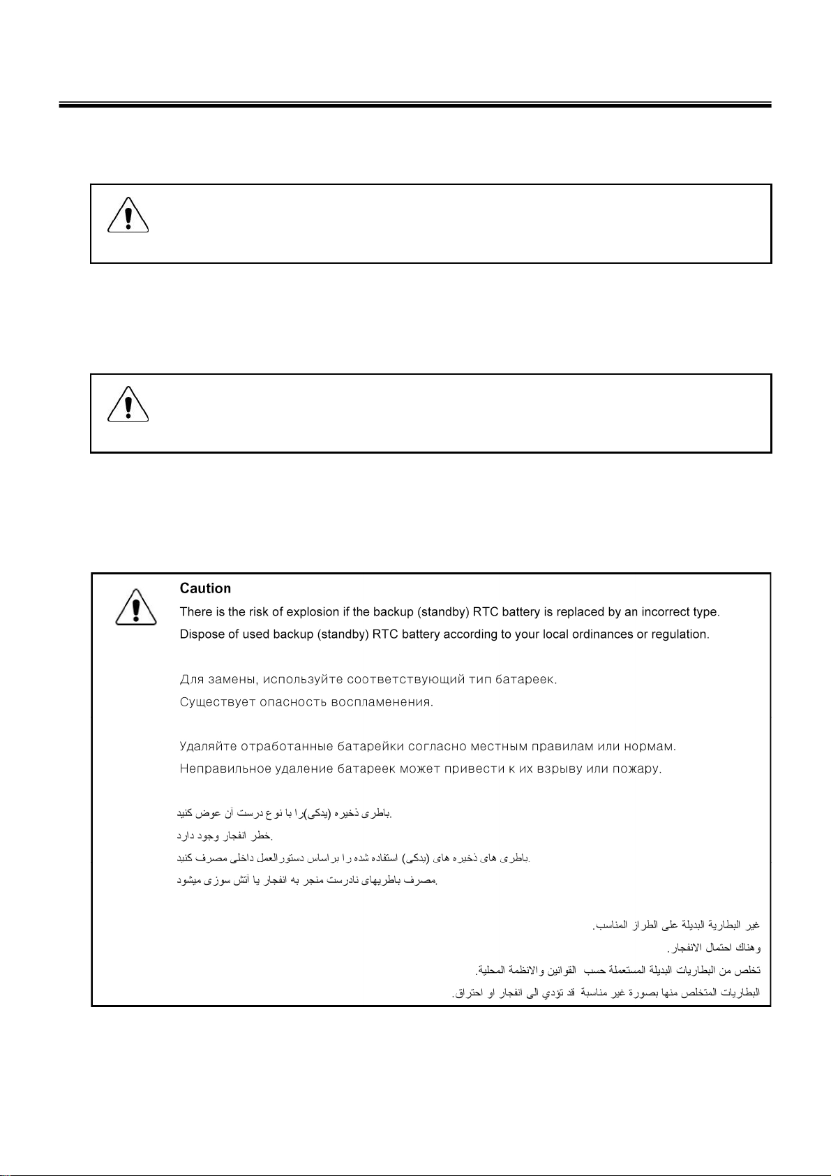
1-5. Backup (Standby) RTC battery safety information
When replacing or disposing of the backup (standby) RTC battery, note the following :
10
Page 11

Ch1. Service information
1-6. Read this first
Before you go to the checkout guide, be sure to read this section.
Important Notes
· Only trained personnel certified by LG should service the computer.
· Read the entire FRU removal and replacement page before replacing any FRU.
· Use new nylon-coated screws when you replace FRUs.
· Be extremely careful during such write operations as copying, saving, formatting.
Drives in the computer that you are servicing sequence might have been altered. If you selected an
incorrect drive, data or programs might be overwritten.
· Replace FRUs only for the correct mode.
· When you replace a FRU, make sure the model of the machine and the FRU part number are correct by
referring to the FRU parts list.
· A FRU should not be replaced because of a single, irreproducible failure. Single failures can occur for a
variety of reasons that have nothing to do with a hard ware defect, such as cosmic radiation,
electrostatic discharge, or software errors.
· Consider replacing a FRU only when a problem recurs. If you suspect that a FRU is defective, clear the
error log and run the test again. If the error does not recur, do not replace the FRU.
· Be careful not to replace a non-defective FRU.
What to do first
You must fill out the record form first.
During the warranty period, the customer may be responsible for repair costs if the computer damage was
caused by misuse, accident, modification, unsuitable physical or operating environment, or improper
maintenance by the customer. The following list provides some common items that are not covered under
warranty and some symptoms that might indicate that the system was subjected to stress beyond normal
use. Before checking problems with computer, determine whether the damage is covered under the
warranty by referring to the following :
11
Page 12

Ch1. Service information
The followings are not covered unde r warranty :
· CD panel cracked from the application of excessive force or from being dropped
· Scratched (cosmetic) parts
· Distortion, deformation, or discoloration of the cosmetic p arts
· Cracked or broken plastic parts, broken latches, broken pins, or broken connectors caused by excessive
force
· Damage caused by liquid spilled into system
· Damage caused by improper insertion of a PC Card or the installation of an incompatible card
· Damage caused foreign material in the diskette drive
· Diskette drive damage caused by pressure on the diskette drive cover or by the insertion of a diskette
with multiple labels
· Damaged or bent diskette eject button
· Fusses blown by attachment of a non-supported device
· Forgotten computer password (making the computer unusable)
· Sticky keys caused by spilling a liquid onto the keyboard
The following symptoms might indicate dam ag e caused by non-warranted acti vities :
· Missing parts might be a symptom of unauthorized service or modification.
· If the spindle of a hard-disk drive becomes noisy, it may have been subjected to excessive force, or
dropped.
12
Page 13

Chapter 2. Locations
■ Left View
1. VGA Port
2. Fan louvers
3. LAN Port
4. Modem Port (May vary depending on model.)
Ch2. Locations
5. HDMI Port
6. e-SATA Port (USB-combo)
7. Express Card Slot
8. 6-in-1 Card Slot
(xD/SD/MMC/MMCplus/MS/MS Pro)
■ Right View
9. Microphone Port
10. Headphone Port
11. USB Port
12. USB Port
13. Optical Disk Drive
14. Power Port
15. Kensington lock
13
Page 14

■ Rear View
Ch2. Locations
①
16. Fan louvers
■ Front View
②
④
③
17. Built-in Microphone
(May vary depending on
model.)
18. LG Smart Cam
(May vary depending on
model.)
19. Power Button
20. Keyboard
21. Touchpad
22. Stereo speaker
14
Page 15

Ch3. System information
Chapter 3. System information
Specification
- Processors
• Intel Core2 Duo/Solo/Mobile Intel Celeron Processor™(L2 Cache Size: 1MB/2MB/4MB/6MB/8MB,
FSB:533/800MHZ are supported.)
The user must not replace or expand the CPU capacity arbitrarily. The CPU capacity differs depends on
model type.
-Main Memory
· Maximum Capacity: Each slot is 2048MB and can be expanded to 4096MB.
· SO DIMM Type for Memory Expansion: DDR2/DDR3 SDRAM SO-DIMM(256MB, 512MB, 1024MB,
2048MB)
Memory types and specifications may differ by model type.
To use two 2GB memory cards, the machine must run on 64bit OS. 32bit Vista/XP OS does not support
4GB memory.
- Secondary Storage
· 2.5" Hard Disk Drive (S-ATA)
· The hard disk capacity and the type depend on the notebook PC model.
· Optical Di sk Drive
· The specifications may differ by model type.
-LCD
· 15.4" WXGA (1280 x 800) TFT Color LCD
· 15.4" WXGA LED (1280 x 800) TFT Color LCD
· 15.4" WXGA+ LED (1440 x 900) TFT Color LCD
Some models are equipped with Glare Type LCD. This model is enhanced the sharpness compare to the
other types of LCD. So, it may appears glaring a lot but this is the normal status.
The size and the resolution rate of the LCD depend on the notebook PC model.
- Authentication for Anti copy Technology
· U.S Patent Nos.4,631,603;4,577,216;4,819,908;4,907,093;5,315,448;and 6,516,132. Patent number of
Macrovision.
This product includes the technologies that are possessed by Macrovision and corresponding companies
and protected by the US Patent Law and other related laws. Use of all technologies subject to the copyrig
ts must be approved by Macrovision in advance. Otherwise, the technologies may only be used for intern
al display. Do not disassemble or remodel the product.
- Bluetooth
· Qcom, QBTM300 / LGIT RBDS-C001X
· Ver2.0 Bluetooth Module
· Bluetooth is optional, and so it may not be installed in some models.
-Web Camera
· 1.3 Mega pixels USB camera module
· UVC(USB Video Class) driver support
※ Web Camera is optional, and so it may not be installed in some models
15
Page 16

Chapter 3. System information
Specification
- External I/O Interface
· Microphone Input Port (Mic in): 1
· Headphone Port: 1
· HDMI Port: 1
· e-SATA (USB Combo) Port: 1
· USB 2.0 Ports: 2
· Multi-card Slot: 1
· Express Card Slot: 1
· RJ 11 (Modem) Port: 1
· USB 2.0 Ports: 4
※
The support availability may differ by model type.
· RJ 45 (LAN) Port: 1
-Video
· Mobile Intel Graphic Media Accelerator 4500MHD (Dynamic Video Memory Technology)
The DVMT actively utilizes part of the system memory when processing large graphic data like 3D graphics.
Therefore, the size of the graphic memory is displayed as the sum of the actual graphic memory size and
the utilized amount of memory, which is decided by the size of system memory.
· NVIDIA Geforce 9600M GT (W/GDDR3 256M ) with TurboCache 320MB~1535MB
· NVIDIA Geforce 9600M GT (W/GDDR3 512M) with TurboCache 576MB~1791MB
· NVIDIA Geforce 9300M GS (W/GDDR3 256M) with TurboCache 320MB~1535MB
TurboCache - This technology actively utilizes part of the System Memory when processing large graphic
data like 3D graphics. The size of the utilized memory is determined by the Video Memory size and System
Memory Size.
If TurboCache technology is applied to the Graphics Memory, the System Memory can allot up to 320MB
out of 512MB and up to 1791MB out of 4096MB for large graphic data.
※
Specifications may differ by model type.
- Sound
· Realtek High Definition Audio Codec (ALC262) HDMI is supported
· Built-in Stereo Speakers
-MODEM
· AGERE Delphi D40
· RJ 11 Jack
※
The support availability may differ by model type.
-LAN
· Intel 82657LM/LF PCI Express Fast Ethernet Controller
· RJ 45 Jack
※
Specifications may differ by model type.
- Wireless LAN
· Intel 512AG_MMW / 512AN_MMW / 533AN_MMW
· Ralink RT2700E
※
Wireless LAN specifications may differ by model type and cannot be arbitrarily changed by the user.
-Weight
· Full Installation: About 2.7kg (2.5kg when using Weight Saver)
· Battery: About 320g
※
Weight descriptions may differ by model type.
16
Page 17
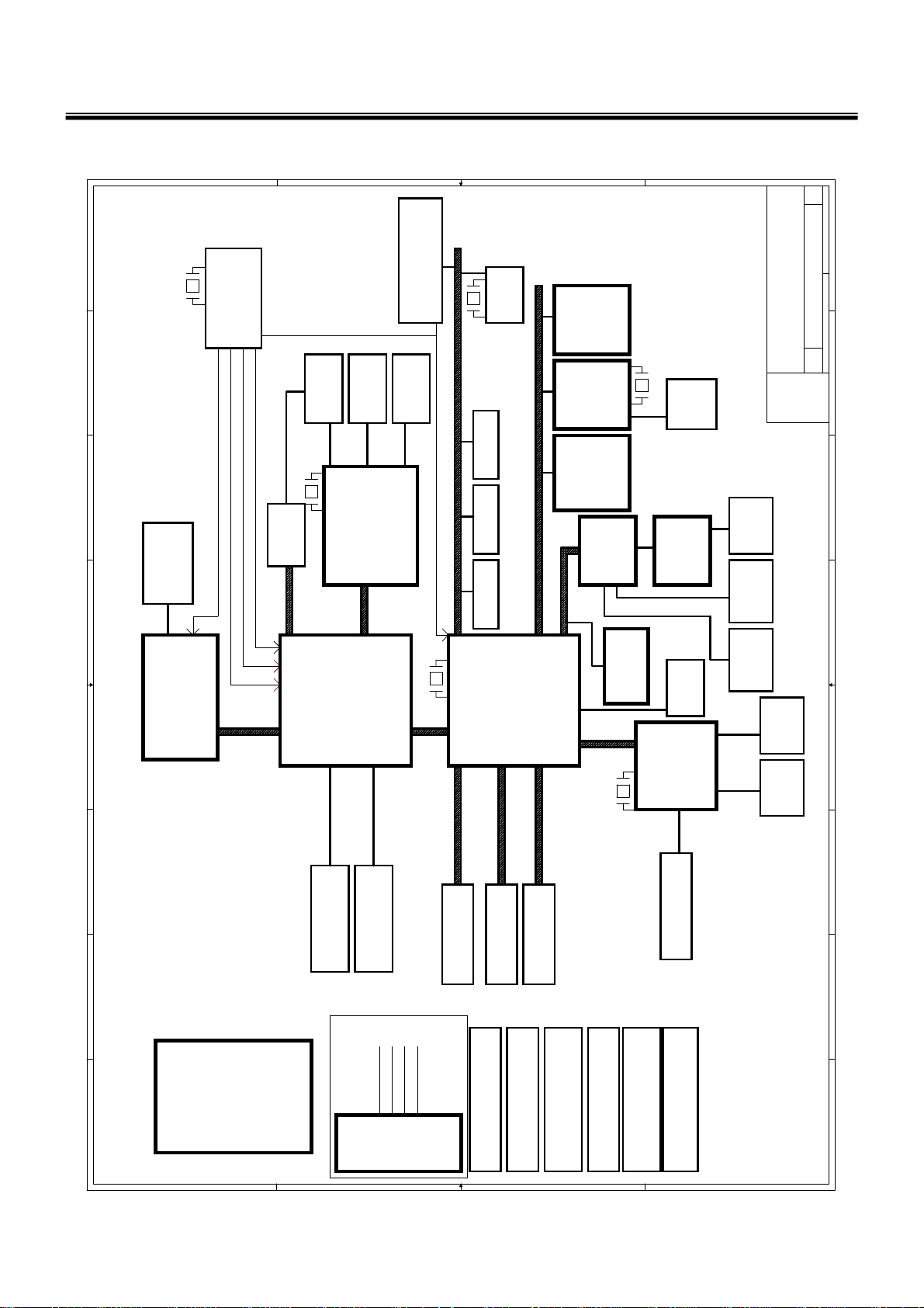
■ System Block Diagram
Chapter 3. System information
B
7
0
11
4
01
8
PAGE 2
14.318MHz
CLOCK GEN
ALPRS355B MLF64PIN
7
PAGE 20
HDMI CON
6
DREFCLK,DREFCLK#
DREFSSCLK,DREFSSCLK#
CLK_CPU_BCLK,CLK_CPU_BCLK#
CLK_MCH_BCLK,CLK_MCH_BCLK#
PAGE 5
CPU THERMAL
SENSOR
5
27MHz
PS8101
PAGE 20
NVIDIA NB9M-GS
64bit or
16X
PCI-Express
10
Mini PCI-E(WWAN)
Mini PCI-E(WLAN)
E-SATA x1
Docking x1
Express Card x1
PAGE 20
CRT
PAGE 19
LCD CONN
Dual Link
969p
NBSRCCLK, NBSRCCLK#
PAGE 12~18
NB9P-GE2 128bit
6
12MHz
9
8
USB2.0
1,2
PAGE 25
RTS5158E
PAGE 19
Webcam
PAGE 26
BlueToothUSB2.0 Ports
PAGE 26
X2
PCI-E
X2 X1 X1
Azalia
Express
Card
PCIE-LAN
LAN
Realtek
RTL8102E/8111C
(Wireless
LAN/WWAN)
Mini PCI-E
Card
Analog
PAGE 30
(NEW CARD)
PAGE 28,29
(10/100/GagaLAN)
PAGE 33
PAGE 26
Azalia ALC268
25MHz
AUDIO
RJ45
PAGE 28
PAGE 27
Amplifier
TPA6017A2
Jack to
Speaker
(Phone/ MIC)
Audio Jacks microphone
veRrebmuN tnemucoDeziS
veRrebmuN tnemucoDeziS
veRrebmuN tnemucoDeziS
3A
3A
3A
of
of
of
8
141Monday, May 12, 2008
141Monday, May 12, 2008
141Monday, May 12, 2008
teehS:etaD
teehS:etaD
teehS:etaD
Block Diagram
Block Diagram
Block Diagram
PROJECT : QL8
PROJECT : QL8
PROJECT : QL8
Quanta Computer Inc.
Quanta Computer Inc.
Quanta Computer Inc.
Custom
Custom
Custom
7
NB5
NB5
NB5
6
PAGE 27
PAGE 26PAGE 19
5
PAGE 3,4
CPU
Penryn
4
478P (uPGA)/35W
Cantiga
32.768KHz
PAGE 5~9
ICH9-M
SOUTH BRIDGE
PAGE 21,22,23,24
PAGE 27
MDC CONN
NORTH BRIDGE
LPC
DMI LINK
FSB 667/800/1066
QL8/TW8(15.4W) BLOCK DIAGRAM
3
2
1
8L
LAYER 2 : SGND
LAYER 1 : TOP
PCB STACK UP
LAYER 3 : IN1
LAYER 4 : SGND1
LAYER 5 : SVCC
LAYER 6 : IN2
DDRII 667/800 MHz
PAGE 10
DDRII-SODIMM1
FOR TW8
LAYER 7 : SGND2
LAYER 8 : BOT
DDRII 667/800 MHz
PAGE 10
DDRII-SODIMM2
Headphone Jack
CRT
LAN/RJ-45
Docking
A A
B
USB Port
PAGE 34
SATA0 150MB
PAGE 30
SATA - HDD
SYSTEM CHARGER(ISL6251AHAZ-T)
SATA5 150MB
SATA1 150MB
PAGE 30
PAGE 31
E-SATA
SATA - CD-ROM
PAGE 36
PAGE 35
SYSTEM POWER ISL6237IRZ-T
VCCP +1.5V AND GMCH
C C
PAGE 37
CPU CORE ISL6266A
1.05V(RT8204)
32.768KHz
PAGE 38
SPI
PAGE 22
PAGE 32
ENE KBC
KB3926 C0
PAGE 32
Touch Pad
Keyboard
PAGE 40
PAGE 39
VGACORE(1.025V)Oz8118
DDR II SMDDR_VTERM
1.8V/1.8VSUS(TPS51116REGR)
SPI
G995
D D
PAGE 32
FAN
PAGE 34
4
3
2
1
17
Page 18

Chapter 3. System information
Fn key combinations
The following table shows t he fun ctio n of each com bin ati on of Fn with a functi o n key .
Function of Fn keys has nothing to do with Operating System.
Fn + F1
Fn + F2
Fn + F3
Fn + F4
Fn + F5
Fn + F6
Fn + F7
Fn + F8
Fn + F9
Customizable hot keys. (Configurable through OSD settings)
Customizable hot keys. (Configurable through OSD settings)
Magnifying hot keys.
Executes the mode defined in the Windows Power Save Mode. (Example: Standby, Hibernate)
When the user presses Fn + F5 keys, the touchpad mode alternates between Touchpad Disable,
Touchpad Auto-Disable (upon connection of external USB mouse), and Touchpad Enable in order.
(Initialization takes 1 ~ 2 seconds. It is recommended to use after the initialization.)
Turns the wireless devices (incl. Wireless LAN and Bluetooth) on and off (Bluetooth is optional, and
so it may not be installed in some models.)
Through hot key settings in the OSD Tray menu, the user can customize [Fn]+[F6] features. Default
setting is, for all wireless devices (incl. Wirele ss LAN and Bluetooth), ON/Off.
Monitor toggle. If you have an external monitor connected to the computer, press Fn + F7 keys to
rotate the display mode between LCD only, Monitor only, and LCD + Monitor both in order.
Switches between SRS WOW HD, SRS TruSurround XT, and SRS Off for each pressing.
Mute (Sound ON / Sound OFF)
Fn + ▲
Fn + ▼
Fn + ◀
Fn + ▶
Fn + F10
Fn + F11
Fn + F12
Fn + NumLk
Increases LCD brightness within a nine-grade range.
Decreases LCD brightness within a nine-grade range.
Turns down the volume.
Turns up the volume.
System Information. Displays summarized system information.
Fan Control feature. Switches the cooling fan mode between Normal and Silent for each pressing.
Hibernates (W hen OSD is installed)
Turns the numeric keypad on and off.
“Delete” key types” “· when Num Lock is enabled, and work as a "Delete" key when Num Lock is
disabled.
18
Page 19
Ch3. System information
Status indicators
The system status indicators show the status of the computer
1 . Power Lamp:
• Blinking: System Standby
• On: The system is running on the AC power or battery.
• Off: The system is turned off or in Hibernates.
2. AC Power and Battery Status Lamp
• Orange: The battery is being charged.
• Orange/Green Blinking: Charged more than 90%
• Off: The AC adapter is not connected and the battery is being discharged.
• Green: The AC adapter is connected and the battery is not in charging stage, or the battery is fully
charged.
• Green Blinking: The battery is charged less than 10%
• Red Blinking: In faulty state
• If you try to turn on the system that has entered the Hibernates mode or been turned off after a low-battery
alarm, the system will not be turned on but the lamp will blink three times.
3. Hard Disk Drive Lamp
• The lamp is turned on when the HDD is running.
※
Do not turn off the power forcibly while the hard disk drive lamp is on. Otherwise, the data may get
impaired.
4. Num Lock lamp
• You can activate Num Lock feature by pressing the Num Lk key. Then, the NumLock lamp will be turned
on and you can input numbers (0 ~ 9) using the numeric keypad. Press the Num Lk key again to turn off
the feature and use the keys as the lowercase signs including arrows indicate.
5. Caps Lock lamp
• Caps Lock lamp is on when the it is active. When this lamp is on, you can type uppercase letters without
holding Shift key.
19
Page 20

6 . Wireless LAN/Bluetooth lamp
• Off: Wireless LAN/Bluetooth is not in use.
• Blinking (short interval): Wireless LAN/Bluetooth is connected and data are being transmitted.
• Blinking (every 2 ~ 3 seconds): Wireless LAN/Bluetooth is not connected but Wireless Radio is on.
• Blinking (every 3 ~ 4 seconds): An access Point is being searched for to connect Wireless LAN/Bluetooth.
• On: An access point is being searched for or Wireless LAN/Bluetooth is connected.
※
The Wireless LAN/Bluetooth lamp may operate differently depending on model type.
※
The Wireless LAN card and the Bluetooth device are optional, and so it may not be supported in some
models.
Ch3. System information
20
Page 21
Ch3. System information
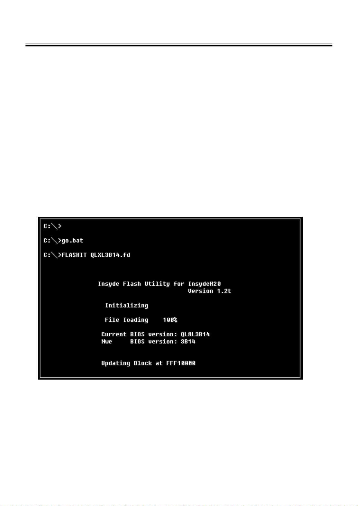
■BIOS Flash
You Can update BIOS using USB Device (FDD/USB Memory)
Because this system is not equipped with any USB Device, you have to use an external USB Device
for a BIOS update.
In order to boot up with an USB Device, please set Removable Device as the
first boot up drive in the boot menu of BIOS Setup.
· How to update flash Rom in Dos
1. Create ‘boot up’ flash update USB Device (FDD/USB Memory).
2. Copy BIOS Flash software to the flash update USB Device (FDD/USB Memory).
3. Connect the USB Device for USB Port.
4. Press F12 Key while the "LG LOGO" appears.
5. A while later, the system setup home screen appears.
6. Type in “go.bat ”. (x_xxx is Model Name & BIOS version)
7. You can see the BIOS flash process as below.
8. After flashing is completed, The computer turn off with automatic movement. .
21
Page 22

Ch3. System information
10. Press [F2] Key, then you can see the BIOS SETUP UTILITY screen as below.
11. It selects the :” Load Optimal Dafault” and it summons a BIOS settings at initial value.
22
Page 23

Ch3. System information
12. It selects the “Exit & Saving Change” and it stores system a settings and the reboot
23
Page 24

Ch3. System information
BIOS Release Process and Making Bootable CD
1. LGE(Korea) will upload BIOS Image(*.iso) to GCSC(Global Cyber Service Center:http://biz.lgservice.com)
when BIOS should be updated.
2. BIOS will include both System BIOS and EC(Embedded Controller) BIOS.
3. Service center can download BIOS file from GCSC and update BIOS according to below procedure.
4. Service center will make Bootable Image CD with Image file(*.iso) as below
a. Insert empty disc to CD-RW Drive and start Nero “StartSmart”.
b. Select “Nero Express”.
24
Page 25

Ch3. System information
c. Select “Disc Image or Saved Project”
d. Select File Format as "Image Files(*.iso)".
25
Page 26

Ch3. System information
e. Open Image File(*.iso) which is sent from LGE
f. Tab Burn then burning will be started
26
Page 27

Ch3. System information
g. Burn process completed as below, and tab “OK
27
Page 28
Ch3. System information
BIOS/EC Flash Process
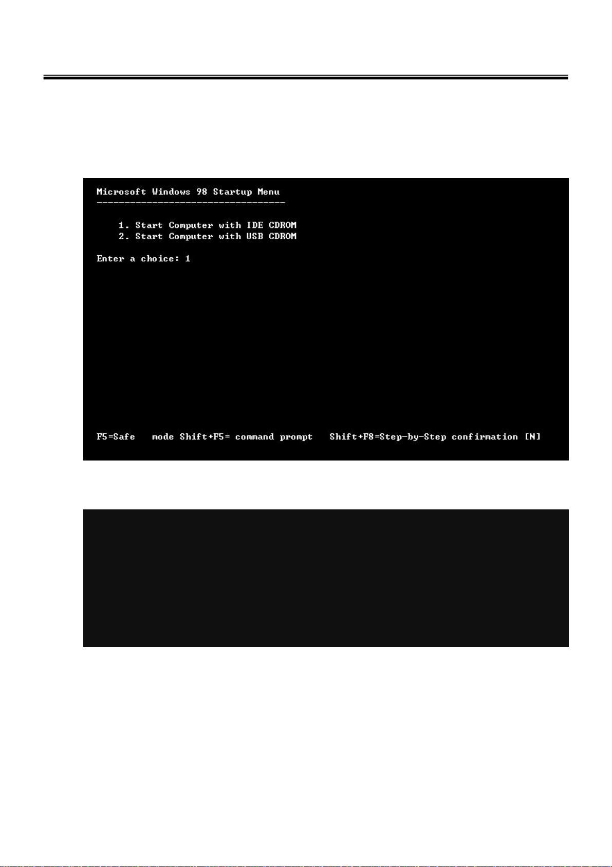
1. Insert Bootable CD in PC, and Turn it on, then PC will boot by DOS mode as below
(If the EC is not correct or old version, then automatically update EC first and reboot again)
2. Select Boot mode, then press “Enter” Key.
3. Type in LOGO SETTING at the “WIP ID :” then press Enter key (You must use Capital Letter)
28
Page 29

Ch3. System information
4. Type in Mode Name at the “WIP ID :” then press Enter key (You must use Capital Letter)
(You can see the Model Name in ID Label at the bottom Case of PC: “M/N: LMXX-XXXX”)
5. Type in Serial No at the “WIP ID :” then press Enter key (You must use Capital Letter)
(You can see the Serial No in ID Label at the bottom Case of PC: “S/N: 412KIXXXXXXXX”(13digits))
6. You can see the BIOS flash process as below
29
Page 30

Ch3. System information
5. After flashing is completed, you can see the “PASS” on your screen, and reboot your PC
30
Page 31

Ch3. System information
BIOS Setup
BIOS (Basic Input and Output System) Setup saves the sy st em co nfigurat io n in CMOS RAM, and
check the configurations during startup. Use the BIOS Setup Utility to change and save the system
environment, hardware configurations, power saving mode, etc.
· Open the BIOS Setup Utility in the following situations :
1. to change the BIOS setup
2. to replace the backup battery
3. system configuration error occurs
4. to change the boot order
5. to set/change a password
Press the power button.
When the LG logo appears on the screen, press and enter the BIOS Setup Utility.
31
Page 32

Ch3. System information
Using the keys
The keys used in the BIOS Setup Utility and their functions are described at the bottom.
· , + : General Help
Display the descriptions of the keys used in the setup utility.
· , : Select Item
Navigate and select items in the setup utility. The selected item becomes highlighted.
· , : Select Menu
Move to another menu.
· / , : Change Values
Change the value of a selected item.
· : Load Default Configuration
Display Setup Confirmation window. Press Enter to load default configuration.
· : Select Sub-Menu
Some items have sub-menus. Display the sub-menu for a selected item.
· : Save and Exit
Display Setup Confirmation window. Press Enter to save and exit.
·: Exit
In a sub-menu, press Esc to move to the previous window. In Main menu, click Esc to move to Exit menu.
32
Page 33

Main menu
Ch3. System information
· System Time
Current time. To change the value, press <+> or <−> key.
· System Date
Current date. To change the value, press <+> or <−> key.
· SATA Hard Drive
This shows the description of the drive connected to the SATA port.
To change the settings of the connected drive, click <Enter> after selecting this option.
· CD-ROM/DVD-ROM
This shows the description of the drive connected to the ODD drive port.
To change the settings of the connected drive, click <Enter> after selecting this option.
33
Page 34

Advanced menu
Ch3. System information
· USB BIOS Legacy Support
This enables to use the USB devices in the MS-DOS environment.
· HDC Configure as
This configures the compatibility settings for the SATA controller.
· VT Support
Set whether or not to support the Intel virtualization technology.
· AC Mode Fan always on
Select any of Normal, Silent, and Cool for the operating speed of CPU cooling fan (for AC power).
· DC Mode Fan always on
Select any of Normal, Silent, and Cool for the operating speed of CPU cooling fan (for DC power).
· Mute button option
Set whether or not to support the Mute function (Fn + F9) during the system startup.
· Internal Devices Configurations
Set whether or not to use the devices such as Auiod, LAN, Wireless, Card reader, Express carder, and
such.
34
Page 35

Security menu
Ch3. System information
· Supervisor Password
The password setting prevents not allowed users from using the notebook computer. The password is not
set when starting the system for the first time. When the system is turned on, any other user cannot
change the BIOS settings without entering the specified password.
· User Password
Set User Password is for setting the password lower than the one set in Set Supervisor Password. Set
User Password is active only when the supervisor password is set.
· Set Supervisor Password
Set Supervisor Password.
· Set User Password
Set User Password.
· Set All Hdd Password
Set the HDD password.
35
Page 36

Boot menu
Ch3. System information
· Quick Boot
Set whether or not to use Quiet Boot.
· PXE Boot to LAN
Set whether or not to use the HDD password.
· Boot Device Priority
Select the desired device drive by using the arrow buttons and change its booting sequence by using the
[+] or [-] key.
36
Page 37

Info menu
Ch3. System information
· BIOS Version
This shows the Version of BIOS.
· KBC Version
This shows the Version of KBD firm ware.
· Serial Number
This shows the serial number of the product.
· CPU Type
This shows the type of the CPU installed in the system.
· L2 Cache RAM
This shows the size of L2 Cache RAM for the CPU.
· Total Memory
This is for display only. This shows size of system memory.
· Slot 1–3 Memory
This shows the size of the memory installed in the memory slot.
37
Page 38

Exit menu
Ch3. System information
· Exit & Save Change
Save the changes you have made and exit the utility.
· Exit & Discard Changes
Exit the utility without saving the changes you have made.
· Load Optimal Defaults
This changes the parameters in the Setup menu to the factory default settings. When it is selected or [F9]
key is pressed, the confirmation message appears. Click [Yes] to change the settings.
· Load Custom Defaults
This returns the user-defined settings for the parameters in the Setup menu.
· Save Custom Defaults
This saves the desired values for each parameter in the Setup menu.
· Discard Changes
This returns to the factory default settings for each parameter in the Setup menu.
38
Page 39

Ch3. System information
■ Backup and Restore Security Platform Data
Security Platform Backup includes all data required in case of emergency. After a hardware or storage
media failure or a Trusted Platform Module failure, Security Platform Restoration reestablishes access to
Security Platform Features for all users.
In addition you can backup and restore your Personal Secure Drive data. Data from other applications
using the Security Platform Solution (e.g. Secure e-mail) is not included in Security Platform backup.
■ Backup scope
Security Platform backup comprises the following data:
Security Platform Credentials and Settings
Backup Contents
Purpose
Archives
Emergency Recovery
Backup Contents
Purpose
A copy of the user-specific credentials and settings which are stored on the
Security Platform.
Restoration of user-specific credentials and settings after a hardware or
storage media failure.
Otherwise users could not access Security Platform Features anymore
and user data would be lost.
•
Automatically written Backup Archive ("System Backup Archive",
e.g. file
Security Platform Administrator. Contains credentials and settings of all
Security Platform Users (for one or multiple Security Platform
computers). Also contains computer identification and user
identification, which are used to match computers and users during the
restoration process.
•
Manually written Backup Archive (e.g.
Created by Security Platform User. Contains credentials and settings of
one Security Platform User (for one Security Platform computer). Also
contains computer identification and user identification, which are used
to match computer and user during the restoration proces s.
All Security Platform Basic User Keys, encrypted specifically for Emergency
Recovery.
Re-encryption of all Basic User Keys after a Trusted Platform Module failure.
In this case a new Security Platform has to be set up and a new owner
key is created. Emergency Recovery allows the re-enc ryption of Basic
User Keys from the old owner key to the new one.
Otherwise users could not access Security Platform Features anymore
and user data would be lost.
SPSystemBackup.xml
and folder
SPSystemBackup
SPBackupArchive.xml
): Set up by
):
Archives
•
Emergency Recovery data is included in automatically written
Backup Archives.
•
Emergency Recovery Token (e.g.
Security Platform Administrator. Protected with a dedicated password.
Is required for a restoration of Emergency Recovery data.
SPEmRecToken.xml
): Created by
39
Page 40

Personal Secure Drive
Ch3. System information
A copy of the PSD encrypted data and configuration settings.Backup Contents
Purpose
Archives
Restoration of PSD encrypted data and configuration settings after a
hardware or storage media failure.
Otherwise users could not decrypt their PSD data anymore.
Notes:
•
In contrast to the PSD Backup, standard hard disk backup tools
produce unencrypted backups.
•
Lost PSD credentials can only be restored via Personal Secure Drive
Recovery.
•
PSD configuration settings are included in both automatically
written Backup Archives and manually written Backup Archives.
•
PSD backup file (e.g.
image file may be created during a Security Platform User's manual
backup.
SpPSDBackup.fsb
■ Restoration Cases
Depending on the type of emergency there are different restoration cases
Affected Restoration ScopeRestoration Case
Broken hard disk or lost data
Security Platform Credentials and Settings, Personal
Secure Drive
Emergency RecoveryNew Trusted Platform Module
): A backup copy of the PSD
New Security Platform to be initialized
Emergency Recovery, Security Platform Credentials
and Settings, Personal Secure Drive
40
Page 41

Ch3. System information
■ How to Backup and Restore
("System Backup")
Software Component to useHow to configure automatic backups
Administrative Task: Configure automatic
backups for all users (including Security
Platform Credentials and Settings,
Emergency Recovery and PSD configuration
settings).
current user.
certain users.
User Task: Run restoration manually for
current user. If restoration has been
prepared for current user, then complete the
restoration.
If a manually written Backup Archive is
available and no Emergency Recovery data
needs to be restored, then a user can
perform restoration without preparation by
an administrator.
■ Backup
If Security Platform is not yet initialized:
Initialization Wizard
If Security Platform is already initialized: Settings
Tool -Backup -Configure...
Software Component to useHow to backup ("Manual Backup")
Settings Tool - Backup - Backup...User Task: Run backup manually for the
Software Component to useHow to restore
Settings Tool - Backup - Restore...Administrative Task: Prepare restoration for
With this page you can configure automatic Security Platform backups.
The following table gives hints on how to use this wizard page.
ExplanationWizard Page Element
Backup location:
Browse...
Schedule...
Security Platform credentials and settings will be regularly save d to a
Backup Archive.
Type in path and file name or browse for it. An automatically written
Backup Archive consisting of an XML file and a folder with the same name
will be created, e.g. file
Please use the extension *.xml.
A scheduled backup will be created.
Click here to view and modify the backup scheduling.
Please note that automatic backups are only executed if your PC is not
shut down at the scheduled time.
Please note that the user account chosen for the scheduled backup must
be member of the group "Administrators" or "Backup Operators".
SPSystemBackup.xml
and folder
SPSystemBackup
.
41
Page 42

Ch3. System information
■ Infineon Platform Security Backup
With this page you can backup and restore Security Platform credentials, Security Platform settings and
Personal Secure Drives.
If Enhanced Authentication is enabled, you can also create backups of your authentication device.
Availability of page: This page is only available on an initialized Security Platform, if one of
the following conditions is fulfilled:
•
The current user has administrative rights.
•
The current user is an initialized Security Platform User, and the policy Allow User Enrollment
is enabled.
Buttons:
•
Buttons for administrative tasks are disabled for users without administrative rights.
•
Buttons are disabled, if corresponding functions are not available in a certain Security Platform
state.
The following table describes all backup and restore functions.
Explanation
Click here to set up automatic Security Platform backups.
Infineon Security Platform Initialization Wizard will be started.
This feature is only available, if the current user account has administrative rights.
Click here to start a manual backup of your Security Platform Settings and credentials. If you have
configured Personal Secure Drive (PSD), you can backup your PSD too.
The Infineon Sec urity Platform Backup Wizard will be started.
This button is disabled, if the Infineon Security Platform is disabled, not yet set up or the user is not
set up.
Click here to start a manual restore of archived Security Platform Settings and credentials. If you
have a backup of your Personal Secure Drive (PSD), you can restore your PSD too.
The restore part of the Infineon Security Platform Backup Wizard will be started.
This button is disabled, if the Infineon Security Platform is disabled or not yet set up.
Click here to create a backup authentication device.
This feature is only available, if Enhanced Authentication is enabled.
42
Page 43

Ch4. Symptom-to-part index
Chapter 4. Symptom-to-part index
The symptom-to-part index in this section lists symptoms and errors and their possible causes.
The most likely cause is listed first.
Note
If replacing a part (FRU) does not solve the problem, put the original part back in the computer.
Do not replace a non-defective FRU.
Power system checkout
· To verify a symptom, do the following :
1. Power off the computer.
2. Remove the battery pack.
3. Connect the AC adapter.
4. Check that power is supplied when you power on the computer.
5. Power off the computer.
6. Disconnect the AC adapter and install the charged battery pack.
7. Check that the battery pack supplies power when you power on the computer.
· If you suspect a power problem, see the appropriate one of the following power supply checkouts :
1. Checking the AC adapter
2. Checking the operational charging
3. Checking the battery pack
4. Checking the backup battery
· Checking the AC adapter
If the power-on indicator does not turn on, check the power cord of the AC adapter for correct continuity
and installation.
If the computer does not charge during operation, go to “Checking operational charging.”
43
Page 44

Ch4. Symptom-to-part index
To check the AC adapter, do the following :
1. Unplug the AC adapter cable from the computer.
2. Measure the output voltage at the plug of the
AC adapter cable. See the following figure :
3. If the voltage is not correct, remove the power code
2
1
form AC adapter.
4. 10 seconds later, connect the power code, then measure the output voltage.
5. If the voltage is not correct, change the AC adapter.
Voltage (V dc)Pin
+18.05 ~ +19.951
Ground2
44
Page 45

Ch4. Symptom-to-part index
· If the voltage is not correct, replace the AC adapter.
· If the voltage is acceptable, do the following :
1. Replace the system board.
2. If the problem persists, check the AC adapter whether it is correct product or not.
Note
Noise from the AC adapter does not always indicate a defect.
· Checking operational charging
1. To check whether the battery charges properly during operation, use a discharged battery pack or a
battery pack that has less than 50% of the total power remaining when installed in the computer.
Perform operational charging. If the battery status indicator or icon does not turn on, remove the battery
does not turn on, replace the battery pack.
2. If the charge indicator still does not turn on, replace thesyst em board.
Then reinstall the battery pack.
Note
Do not charge battery pack, when its temperature is below 0 or above 75 .
· Checking the battery pack
1. Open the Power Meter window by clicking Start Control Panel Power Options and then;
check the total power remains. Battery charging does not start until the power Meter shows that less
than 95% of the total power remains; under this condition the battery pack can charge to 100% of its
capacity. This protects the battery pack from being overcharged or from having a shortened life.
2. To check the status of your batter, move your cursor to the Power Meter icon in the icon tray of the
Windows taskbar and wait for a moment (but do not click), and the percentage of battery power
remaining is displayed. To get detailed information about the battery, double-click the Power Meter icon.
Note
If the battery pack becomes hot, it may not be able to charge. Remove it from the computer and
Leave it at room temperature for a while. After it cools down, reinstall and recharge it.
45
Page 46

Ch4. Symptom-to-part index
· The Characteristics of the battery pack
1. Self-discharge
The battery gradually loses its power over time without ever being used.
2. Periodic full discharge / charge
Frequent recharge of the battery pack can reduce the capacity of the battery pack. When this happens,
you can perform the full discharge / charge to improve the capacity. You should perform periodic full
discharge /charge once every 30~60 days.
You should always use the battery until its power is low; then fully charge the battery.
3. Trickle charge
If the temperature of the battery pack drops below 10 , the trickle charging begins.
The trickle charging may take 32 hours for the battery pack to be fully charged.
46
Page 47

Ch4. Symptom-to-part index
· To check the battery pack, do the following :
1. Power off the computer.
2. Remove the battery pack and measure the voltage between batt ery terminals 1(-) and 5(+).
See the following figure :
Voltage (V dc)Terminal
Ground(-)1
5(+) 4 3 2 1(-)
3. If the voltage is still less than +11.1 V DC after recharging, replace the battery.
4. If the voltage is more than +11.1 V DC, measure the resistance between battery terminals 1 and 2.
The resistance must be 2 to 4 (typically 3 ).
5. If the resistance is not correct, replace the battery pack. If the resistance is correct, replace the system
board.
Note
Charging will take at least 3 hours.
Note
Battery is an expendable supplier, so its capacity and used time can be reduced by using the computer.
5
+0V ~ +12.6V
(6 cell)
47
Page 48

Numeric error codes
Ch4. Symptom-to-part index
FRU or action, in sequenceSymptom / Error
0200
Fixed disk failure
(The hard disk is not working)
0210
Stuck Key error
0211
Keyboard error
Keyboard Controller Failed
Monitor type error - Monitor type does not
match the one specified in CMOS.
1.Reset the hard-disk drive.
2.Load Setup Defaults in BIOS Setu p Utility.
3.Hard-disk drive.
4.System board.
1.Check the keyboard if it is pressed.
2.Replace the keyboard.
Run interactive tests of the keyboard a n d th e auxiliary
input device.
System board.0212
Load Setup Defaults in BIOS Setup Utility.0220
0230
System RAM error - System RAM Failed at
offset.
Shadow RAM error - Shadow RAM failed at
offset
0232
Extended RAM error - Extended RAM Failed
at address line
0250
System battery error – System battery is dead
1.DIMM
2.System board
System board0231
1. DIMM
2. System board
Replace the backup battery and run BIOS Setup Utility
to reset the time and date.
48
Page 49

Ch4. Symptom-to-part index
FRU or action, in sequenceSymptom / Error
0251
System CMOS checksum bad
– System CMOS checksum is not correct.
– Default configuration used.
Password checksum bad – The password is
cleared.
0260
System timer error
Check date and time settings – Date and time
error.
0280
Previous boot incomplete
- Default configuration used
from EISA CMOS
Diskette drive A error
Replace the backup battery and run BIOS Setup Utility
to reset the time and date.
Reset the password by running BIOS Setup Utility.0252
1. Replace the backup battery and run BIOS
Setup Utility to reset the time and date.
2. System board.
Run BIOS Setup Utility to reset the time and date.0271
1. Load “Setup Default” in BIOS Setup Utility.
2. DIMM.
3. System board.
Load Setup Defaults in BIOS Setup Utility.0281: Memory Size found by POST differed
Set up the diskette type in BIOS Setup Utility.02B0
Diskette drive B error
02B2
Incorrect drive A type – Floppy diskette drive
error
02B3
Incorrect Drive B type
02D0
System cache error – Cache disabled
(RAM cache failed and BIOS disabled)
02F4
EISA CMOS not writable
02F5
DMA test failed
02F6
Software NMI failed
Set up the diskette type in BIOS Setup Utility.02B1
1. Floppy diskette drive.
2. External FDD cable.
3. I/O card.
1. Floppy diskette drive.
2. External FDD cable.
3. I/O card.
1. Load “Setup Default” in BIOS Setup Utility.
2. System board.
1. Load “Setup Default” in BIOS Setup Utility.
2. Replace the backup battery.
3. System board.
1. DIMM
2. System board
1. DIMM
2. System board
49
Page 50

Ch4. Symptom-to-part index
FRU or action, in sequenceSymptom / Error
02F7
Fail – Safe timer NMI failed
0611
IDE configuration changed
0612
IDE configuration error
0613
Com A configuration changed
0614
Com A configuration error
0615
Com B configuration changed
1. DIMM
2. System board
1. Load Setup Defaults in BIOS Setup Utility.
2. System board.
1. Load Setup Defaults in BIOS Setup Utility.
2. System board.
1. Load Setup Defaults in BIOS Setup Utility.
2. System board.
1. Load Setup Defaults in BIOS Setup Utility.
2. System board.
1. Load Setup Defaults in BIOS Setup Utility.
2. System board.
0616
Com B configuration error
0617
Floppy configuration changed
0618
Floppy configuration error
0619
Parallel port configuration changed
061A
Parallel port configuration error
1. Load Setup Defaults in BIOS Setup Utility.
2. System board.
1. Load Setup Defaults in BIOS Setup Utility.
2. System board.
1. Load Setup Defaults in BIOS Setup Utility.
2. System board.
1. Load Setup Defaults in BIOS Setup Utility.
2. System board.
1. Load Setup Defaults in BIOS Setup Utility.
2. System board.
50
Page 51

Error message
Ch4. Symptom-to-part index
FRU or action, in sequenceSymptom / Error
Device address conflict.
Allocation error for device.
Failing bits: nnnn.
Invalid System Configuration Data.
I/O Device IRQ Conflict.
1. Load Setup Defaults in BIOS Setup Utility.
2. Backup battery.
3. System board.
1. Load Setup Defaults in BIOS Setup Utility.
2. Backup battery.
3. System board.
1. DIMM.
2. System board.
1. DIMM.
2. System board.
1. Load Setup Defaults in BIOS Setup Utility.
2. Backup battery.
3. System board.
Operating System no t foun d.
Hibernation error.
1. Check that the operating system has no failure and
is installed correctly.
2. Enter BIOS Setup Utility and see whether the hard
-disk drive and the diskette drive are properly
identified.
3. Reset the hard-disk drive.
4. Reinstall the operating system.
5. Diskette drive.
6. Hard-disk drive.
7. System board.
1. Restore the system configurati o n to what it was
before the computer entered hibernation mode.
2. If memory size has been changed, re-create the
hibernation file.
Fan.FAN error.
51
System board.Thermal sensing error.
Page 52

Ch4. Symptom-to-part index
LCD-related symptoms
Note
Before removing or disassembling LCD, power off the computer, unplug all power cords from electrical
outlets, remove the battery pack also.
FRU or action, in sequenceSymptom / Error
Check out Battery Miser.LCD screen becomes dark suddenly.
Nothing displayed on LCD screen.
LCD backlight not working.
LCD too dark.
LCD brightness cannot be adjusted.
LCD color cannot be adjusted.
LCD screen abnormal.
Characters missing pixels.
LCD screen unreadable.
Wrong color displayed.
1. Check out Battery Miser.
2. Choose Never in the Turn off Monitor item on
Power Options Properties.
3. Check the power save mode switch if it is pressed
by something.
4. Check the System is in standby or hibernation
mode.
1. Reconnect inverter to the board connector.
2. Replace inverter.
3. LCD Assembly.
4. System board.
1. Reset all LCD connectors.
2. Replace LCD cable.
3. LCD Assembly.
4. System board.
on LCD
Power-on indicator on, and a blank\LCD
during POST.
LCD Assembly.Horizontal or vertical lines display ed
LCD Assembly.
System board.
52
Page 53

Ch4. Symptom-to-part index
Indeterminate problems
· You are here because the diagnostic tests did not identify which adapter or device failed, wrong devices
are installed, a short circuit is suspected, or the system is inoperative.
Follow these procedures to isolate the failing FRU (do not isolate FRUs that have no defects).
· Verify that all attached devices are supported by the computer.
· Verify that the power supply being used at the time of the failure is operating correctly.
1. Power off the computer
2. Visually check each FRU for damage. Replace any damaged FRU.
3. Remove or disconnected all of the following devices :
a. Non-LG devices.
b. Printer, mouse, and other external devices.
c. Battery pa ck.
d. PC cards.
e. ODD (CD-ROM, Combo) drive or FDD drive in the Bay.
f. Hard-disk drive.
Note
Use the other memory card because it needs when operating computer.
4. Power on the computer.
5. Determine whether the problem has changed.
6. If the problem does not recur, reconnect the removed devices one at a time until you find the failing FRU.
7. If the problem remains, replace the following FRUs one at a time.
(do not replace a non-defective FRU)
a. LCD Assembly (Check external monitor whether the same problem recurs or not).
b. Keyboard.
c. Keydeck (TouchPad and Scroll Button Assembly).
d. System board.
53
Page 54

Ch5. Removing and replacing a part
Chapter 5. Removing and replacing a part (FRU)
Danger
Before removing any FRU, power off the comput er, u npl u g all power cords from electrical
outlets, remove the battery pack, and then disconnect any interconnecting cables.
Caution
Before the computer is powered on after FRU replacement, make sure that all screws, springs,
and other small parts are in place and are not loose inside the computer. Verify metal flakes can
cause electrical short circuits.
Note
-As for the screw, every Torque 3 0.2Kgfcm(0.196Nm)
-For further information on Removing an d Re pl a cin g a Part(FRU), refer to Explore view.
54
Page 55

Ch5. Removing and replacing a part
■ 1010 Battery Pack
1. Push the battery latch in the direction shown below; then slide the battery pack out of the slot.
55
Page 56

Ch5. Removing and replacing a part
■ 1020 System Door
※ Remove the following parts in order before replacing this part
a. Battery Pack(1010)
1. Remove the 3 screw.
2. Remove the System Door.
56
Page 57

Ch5. Removing and replacing a part
■ 1030 HDD
※ Remove the following parts in order before replacing this part
a. Battery Pack(1010)
1. Remove 2 screws.
2. Remove the HDD Cover.
57
Page 58

3. Remove the HDD.
제 6장. 부품 해체와 교체
4. Remove the 4 screw.
QtySpecificationFRU No.No.
FAB302490011
FH + 3MM 3.5MM
SWRCH SILVER
4
58
Page 59

5. Remove the HDD Shield.
Ch5. Removing and replacing a part
59
Page 60

Ch5. Removing and replacing a part
■ 1040 ODD
※ Remove the following parts in order before replacing this part
a. Battery Pack(1010)
1. Remove 1 screws.
2. Remove the ODD.
QtySpecificationFRU No.No.
FAB302489011
FH + 2.5MM 6.5MM
SWRCH BZN
1
60
Page 61

Ch5. Removing and replacing a part
■ 1050 Bluetooth Module
※ Remove the following parts in order before replacing this part
a. Battery Pack(1010), b. HDD(1040)
1. Remove the Connector.
2. Remove the HDD Cover.
61
Page 62

Ch5. Removing and replacing a part
■ 1060 WLAN Mod ule
※ Remove the following parts in order before replacing this part
a. Battery Pack(1010), b. System Door(1020)
1. Remove 3 Antenna Cables.
2. Remove the 1 screw.
QtySpecificationFRU No.No.
62
1M2.5*3.0-I(BZN)FAB302551011
Page 63

Ch5. Removing and replacing a part
3. Remove the WLAN Module.
63
Page 64

Ch5. Removing and replacing a part
■ 1070 DIMM
※ Remove the following parts in order before replacing this part
a. Battery Pack(1010), b. System Door(1020)
1. Remove 2 Hooks than remove the DIMM.
Hook
Hook
64
Page 65

Ch5. Removing and replacing a part
■ 1080 CPU/GPU Fan Assembly
※ Remove the following parts in order before replacing this part
a. Battery Pack(1010), b. System Door(1020)
1. Remove 3 screws.
Connector
2. Remove the CPU/GPU Fan Assembly.
Fixed
65
Page 66

Ch5. Removing and replacing a part
■ 1090 CPU
※ Remove the following parts in order before replacing this part
a. Battery Pack(1010), b. System Door(1020)
1. Remove the CPU.
66
Page 67

Ch5. Removing and replacing a part
■ 1100 Modem Module
※ Remove the following parts in order before replacing this part
a. Battery Pack(1010), b. System Door(1020)
1. Remove the 2 Screw, and 1 connector.
Connector
2. Remove the Modem Module.
QtySpecificationFRU No.No.
2EAM2.0*3.0-I-NIFAB302085011
67
Page 68

Ch5. Removing and replacing a part
■ 1110 Reta iner
※ Remove the following parts in order before replacing this part
a. Battery Pack(1010)
1. Remove 2 screws.
2. It uses JIG and it removes the Hooks.
QtySpecificationFRU No.No.
2EAM2.0*3.0-I(BKAG)FAB302550011
68
Page 69

Ch5. Removing and replacing a part
3. Remove the Retainer and 2s crew remove.
QtySpecificationFRU No.No.
69
2EAM2.0*3.0-I(BKAG)FAB302550011
Page 70

Ch5. Removing and replacing a part
3. Remove the Power Button SUB Board.
4. Remove the Retainer.
70
Page 71

Ch5. Removing and replacing a part
■ 1120 Keyboard
※ Remove the following parts in order before replacing this part
a. Battery Pack(1010), b. Retainer / Power Button SUB Board(1110)
1. Remove 1 screws.
QtySpecificationFRU No.No.
FAB302489011
FH + 2.5MM 6.5MM
SWRCH BZN
1EA
71
Page 72

Ch5. Removing and replacing a part
2. Remove the Keyboard Connector.
Connector
3. Remove the Keyboard.
72
Page 73

Ch5. Removing and replacing a part
■ 1130 Display Module
※ Remove the following parts in order before replacing this part
a. Battery Pack(1010), b. Retainer/Power Button SUB Board(1110), c. Keyboard(1120 )
1. Remove 2 screws.
2. Remove the Hinge Cap.
QtySpecificationFRU No.No.
FAB302489011
FH + 2.5MM 6.5MM
SWRCH BZN
2EA
73
Page 74

3. Remove the Connector .
Ch5. Removing and replacing a part
Connector
4. Remove 2 screws.
QtySpecificationFRU No.No.
FAB302489011
FH + 2.5MM 6.5MM
SWRCH BZN
2EA
74
Page 75

Ch5. Removing and replacing a part
5. Remove the Display Module.
75
Page 76

Ch5. Removing and replacing a part
■ 1140 Keyboard deck
※ Remove the following parts in order before replacing this part
a. Battery Pack(1010), b. Retainer/Power Button SUB Board(1110), c. Keyboard(1120 )
d. Display Module(1130)
1. Remove 10 screws.
2. Remove 3 screws.
QtySpecificationFRU No.No.
FAB302489011
FH + 2.5MM 6.5MM
SWRCH BZN
10EA
76
QtySpecificationFRU No.No.
3EAM2.0*3.0-I(BKAG)FAB302550011
Page 77

3. Remove 1 screws.
Ch5. Removing and replacing a part
Connector
FAB302489011
4. Remove the Keyboard deck.
FH + 2.5MM 6.5MM
SWRCH BZN
QtySpecificationFRU No.No.
1EA
77
Page 78

3. Remove the 2 Cable.
Ch5. Removing and replacing a part
Connector
Connector
4. Remove the Display Module.
78
Page 79

Ch5. Removing and replacing a part
■ 1140 USB(R) Sub Board
※ Remove the following parts in order before replacing this part
a. Battery Pack(1010), b. Retainer/Power Button SUB Board(1110), c. Keyboard(1120 )
d. Display Module(1130) e. Keyboard deck(1140)
1. Remove 1 screws.
No. FRU No. Specification Qty
1 FAB30248901
2. Remove the USB(R) Sub Board Cable.
Connector
FH + 2.5MM 6.5MM
SWRCH BZN
1EA
79
Page 80

Ch5. Removing and replacing a part
■ 1160 Mainboard
※ Remove the following parts in order before replacing this part
a. Battery Pack(1010), b. Retainer/Power Button SUB Board(1110), c. Keyboard(1120 )
d. Display Module(1130) e. Keyboard deck(1140) f. USB(R) Sub Board(1150)
1. Remove 1 screws.
No. FRU No. Specification Qty
2. Remove the Mainboard.
FAB302489011
FH + 2.5MM 6.5MM
SWRCH BZN
1
80
Page 81

Ch5. Removing and replacing a part
81
Page 82

Ch5. Removing and replacing a part
■ 1170 RTC Battery
※ Remove the following parts in order before replacing this part
a. Battery Pack(1010), b. Retainer/Power Button SUB Board(1110), c. Keyboard(1120 )
d. Display Module(1130) e. Keyboard deck(1140) f. USB(R) Sub Board(1150)
1. Remove the RTC Battery.
82
Page 83

Ch5. Removing and replacing a part
■ 1100 Heatsync
※ Remove the following parts in order before replacing this part
a. Battery Pack(1010), b. System Door(1020)
1. Remove 3 screws.
2. Remove the Heatsync.
Fixed
83
Page 84

Ch5. Removing and replacing a part
■ 1190 AC Connector
※ Remove the following parts in order before replacing this part
a. Battery Pack(1010), b. Retainer/Power Button SUB Board(1110), c. Keyboard(1120 )
d. Display Module(1130) e. Keyboard deck(1140) f. USB(R) Sub Board(1150), g. Mainboard(1160)
1. Remove 1 screws.
2. Remove the AC Connector.
QtySpecificationFRU No.No.
1EAM2.0*3.0-I-NIFAB302085011
84
Page 85

Ch5. Removing and replacing a part
■ 1200 LAN Connector
※ Remove the following parts in order before replacing this part
a. Battery Pack(1010), b. Retainer/Power Button SUB Board(1110), c. Keyboard(1120 )
d. Display Module(1130) e. Keyboard deck(1140) f. USB(R) Sub Board(1150), g. Mainboard(1160)
1. Remove the LAN Connector.
85
Page 86

Ch5. Removing and replacing a part
■ 1210 Speaker
※ Remove the following parts in order before replacing this part
a. Battery Pack(1010), b. Retainer/Power Button SUB Board(1110), c. Keyboard(1120 )
d. Display Module(1130) e. Keyboard deck(1140) f. USB(R) Sub Board(1150), g. Mainboard(1160)
1. Remove 2 screws.
2. Remove the Speaker.
QtySpecificationFRU No.No.
2EAM2.5*3.0-I(BZN)FAB302551011
86
Page 87

Ch5. Removing and replacing a part
■ 1220 Battery Latch
※ Remove the following parts in order before replacing this part
a. Battery Pack(1010), b. Retainer/Power Button SUB Board(1110), c. Keyboard(1120 )
d. Display Module(1130) e. Keyboard deck(1140) f. USB(R) Sub Board(1150), g. Mainboard(1160)
1. Remove the Latch.
87
Page 88

Ch5. Removing and replacing a part
■ 1230 LCD Front Case
※ Remove the following parts in order before replacing this part
a. Battery Pack(1010), d. Retainer/Power Button SUB Board(1110) c. Display Module(1130)
1. Remove 4 Rubber and 4 remove Screw.
No. FRU No. Specification Qty
1 FAB30248901
2. Remove the LCD Front Case.
2.5MM 6.5MM
SWRCH BZN
4EA
88
Page 89

Ch5. Removing and replacing a part
89
Page 90

Ch5. Removing and replacing a part
■ 1240 LCD Assembly
※ Remove the following parts in order before replacing this part
a. Battery Pack(1010), d. Retainer/Power Button SUB Board(1110) c. Display Module(1130)
d. LCD Front Case(1230)
1. Remove 4 screw.
No. FRU No. Specification Qty
1 FAB30248901
2. Remove the LCD Assembly.
2.5MM 6.5MM
SWRCH BZN
4EA
90
Page 91

Ch5. Removing and replacing a part
91
Page 92

Ch5. Removing and replacing a part
■ 1250 LCD Panel
※ Remove the following parts in order before repl acing this part
a. Battery Pack(1010), b. Retainer(1070), d. Button Sub Board(1140), e. Display Module(1150)
F. LCD Front Case(1230)
1. Remove 4 screws.
2. Remove the LCD Panel.
QtySpecificationFRU No.No.
4EAM2.0*3.0-I-NIFAB302085011
92
Page 93

Ch5. Removing and replacing a part
3. Remove the inverter cable.
Cable
4. Remove the LCD Panel.
93
Page 94

Ch5. Removing and replacing a part
■ 1260 Inverter
※ Remove the following parts in order before replacing this part
a. Battery Pack(1010), b. Retainer/Power Button SUB Board(1110) c. Display Module(1130)
d. LCD Front Case(1230), e. LCD Assembly(1240)
1. Remove 2 Cable.
2. Remove the Inverter.
Cable
Cable
94
Page 95

Ch5. Removing and replacing a part
■ 1270 Web Cam Module
※ Remove the following parts in order before replacing this part
a. Battery Pack(1010), b. Retainer/Power Button SUB Board(1110) c. Display Module(1130)
d. LCD Front Case(1230), e. LCD Assembly(1240)
1. It uses JIG and it Remove the Web Cam module.
2. Remove the Web Cam Module.
95
Page 96

Ch6. P
a
Item
LG P/N
W
W
U
M
M
W
N
N
NMLB01
EBR56977901
QL6 MB ASSY (INTEL,N
T
T
O
W
S
Y
S
N
A
USB/AUDIO B/D
QUA
F
X
B
L
X
NLCD02
EAY54657201
Inverter,DC/AC
C
Part Description
Remark
HYN 256M) W/O CPU
Y
COMPUTER INC
rt lists
Chapter 6. Part lists
Location
No.
NMLB01 EBR56975101 QL6 MB (INTEL,UMA)
NMLB01 EBR61049001 QL6 MB (GM45,UMA)
NMLB01 EBR55379001 QL6 MB ASSY (INTEL,
NMLB01 EBR56975501 QL6 MB (INTEL,9M,QI
NMLB01 EBR55379601 QL6 MB (INTEL,9M,HY
NMLB01 EBR61045901 QL6 MB (INTEL,9M,SA
Main
B/D
SUB
B/D
NMLB01 EBR58438901 QL6 MB (GL40,UMA)
NMLB01 EBR55379801 QL6 MB ASSY (INTEL,
NMLB01 EBR61046001 QL6 MB ASSY (INTEL,
NMLB01 EBR61315101
NMLB01 EBR61315001
NMLB01 EBR63859801
NSUB01 EBR55687801 QL6 PW_BUTTON/B A
NSUB01 EBR60967801
NSUB02 EBR55688701 QL6 USB AUDIO/B AS
NSUB02 EBR60968601
EAD57550302 R410 SVC Audio BD F
NLCD01 EAJ50527801 WXGA 14.1INCH 1280
NLCD01 QL6 LCD 14.1 WXGA (
NLCD01 QL6 LCD 14.1 WXGA (
NLCD01 EAJ58557101 WXGA 14.1INCH 1280
20QL6BU0070 - QUAN
Citrine QL6 9300M GS(
Modem - QUANTA CO
20QL6BU0020 - QUAN
Citrine QL6 MB ASSY (
MODEM - QUANTA C
QL6 MB (GL40,UMA)
1HYEZZZ029V - - 4 LA
ASSY S.P.3DQL6PB00
COMPUTER INC.
1HYEZZZ029W - QUA
SMT)Citirine QL6 USB/
-
/O CPU,MODEM
/O CPU W/O MODEM
MA) W/O CPU
256M) W/O CPU,MODEM
N 256M) W/O CPU,MODEM
)W/OCPU,MODEM
/O CPU/Modem
B9M,QIM 256M) W/O CPU
B9M,SAM)W/O CPU
,
A MICROSYSTEMS INC 8 LAYERS R410
NB9M-GS, 256MB- ALL vendor) W/O CPU W/O
MPUTER INC.
A MICROSYSTEMS INC 8 LAYERS R410
INTEL,NB9M, 256M-ALL vendor) W/O CPU WITH
MPUTER INC.
/O CPU
S
ERS R410 Citrine(for SMT)QL6 PW_BUTTON/B
00 QL6 PW_BUTTON/B ASSY - QUANTA
TA MICROSYSTEMS INC 4 LAYERS R410(for
UDIO B/D ASSY S.P. 3EQL6AB0000 QL6
C Cable
800 - CCFL TYPE
DF)-BV GROUPING
ED)-BV GROUPING
800 - LED TYPE
.
REV.17
added by frank
kim
added by frank
kim
added by frank
kim
LCD
NLCD02 EAY54657301 Inverter,DC/AC
NLCD03 EBP56601301 webcam Module
NLCD03 EAB56601601 webcam Module
NLCD05 ABQ67101101 Front Case Assy (W Ca
NLCD05 ABQ67101102 Front Case Assy (W/O
NLCD06 ABQ67100801 Rear Case (Red_LG)
9
m)
6
-> Quanta P/N
duplicated
-> Quanta P/N
duplicated
Top/mid rubber,
side rubber inc.
am)
Main_Aux
antenna inc.
Page 97

a
Item
LG P/N
)
e
LCD
NLCD06
ABQ67100805
Rear Case LED(Red_LG
n
G
X
D
a
e
A
H
B
H
B
V
ON
NCPU01
EAN56930301
T3400 2.16GHZ
Part Description
Remark
r
MEMO
RY
ROBS
Ch6. P
Location
No.
NLCD06 ABQ67100802 Rear Case (Red_Xnote
NLCD06 ABQ67100803 Rear Case (gray_LG)
NLCD06 ABQ67100804 Rear Case (Gray_Xnot
NLCD06 ABQ67100806 Rear Case LED(Red_X
NLCD06 ABQ67100807 Rear Case LED(gray_L
NLCD06 ABQ67100808 Rear Case LED(Gray_
NLCD08 EAD56807801 CABLE ASSY QL6 LC
NLCD10 MAZ56516501 HINGE - L
NLCD11 MAZ56517301 HINGE - R
NLCD13 MCQ56517601 LCD Front RUBBER
NLCD14 MEZ54122001 Name Label R410 Kore
NLCD14 MEZ54122002 Name Label RB410 Kor
NLCD14 MEZ54122003 Name Label RD410 Glo
NLCD14 MEZ54122004 Name Label RV410 Glo
NLCD15 FAB30255001 SCREW M2.0*3 .0 - I ( BK
NLCD19 EAY60665501 QL6 LED Driver inverte
NLCD19 EAY60665901 QL6 LED Driver inverte
NMEM01 EAN48754301 SODIMM, 1GB, DDR2,
NMEM01 EAN50048601 SODIMM, 1G, DDR2, R
NMEM01 EAN48754401 SODIMM, 2GB, DDR2,
NMEM01 EAN50048701 SODIMM, 2G, DDR2, R
NROB01 EAN51676901 ROBSON CARD 2G N
rt lists
)
ote)
)
note)
(40/40P,REV1A)3V
/Global Consumme
a Commercial
bal Dos free
bal Commercial
G)(NYLOK) IRON
r
r
YMP112S64CP6-S6 ROK B/S
U128X64D2S800C6 ROK B/S
YMP125S64CP8-S6 ROK B/S
U256X64D2S800C6 ROK B/S
CPEMWR002G2 ROK B/S
Main_Aux
antenna inc.
Main_Aux
antenna inc.
Main_Aux
antenna inc.
FBQL6004010>FBQL6034010
FBQL6003010>FBQL6033010
MM20030ICI3
M2.0*3.0
EAN55755411>EAN55755511(
K)
김종원
EAN55755421>EAN55755521(
K)
김종원
CPU
NCPU01 EAN52856301 P7350 2.00G
NCPU01 EAN51676001 P8400 2.26GHZ
NCPU01 EAN51675901 P8600 2.4G
NCPU01 EAN51675701 T9400 2.53G
NCPU01 EAN51675601 T9600 2.8G
NCPU01 EAN60661301 T4200 2GHZ
NCPU01 EAN60666201 P8700 2.53GHZ
9
7
Page 98

Ch6. P
a
a
W
W
P
P
0
L
ODD
NODD02
ACQ67103401
QL6 ODD BEZEL ASSY
H
S
H
NHDD01
EAZ44349304
HDD(320G) MK3252GS
D
D
D
0
P
-
GVL ROK B/S
rt lists
Item Location No. LG P/N
NCPU01 EAN60661201 T6400 2GHZ
NCPU01 EAN60661401 P7450 2.13GHZ
CPU
WLAN
NCPU01 EAN60661101 T6600 2.2GHZ
NCPU01 EAN56930202 T5800 2GHZ
NCPU01 EAN56930402 T1600 1.66GHZ
NCPU01 EAN56930302 T3200 2GHZ
NWLA01 EBM51207601
NWLA01 EBM51208101
NWLA01
NWLA01 EBM54120901 WLAN 802.11 B/G/N 9
NWLA01 EBM54120701 WLAN 802.11 B/G/N 9
EBM54052001
Intel WLAN Shirley Pea
ROK B/S
Intel WLAN Shirley Pea
ROK B/S
Intel WLAN Shirley Pea
B/S
FOR Russia,Ukraine,P
Part Description Remark
k 1x2 AGN,WLAN 802.11ABGN 512AN_MMWG
k 3x3 AGN,W/L 802.11A/G/N 533AN_MMWG
k 1x2 ABG W/L 802.11A/B/G 512AGMMWG ROK
kistan
EM302QCF01Q
EM302QCE02Q
NBLU01 EAT56371601 BLUETOOTH2.1+EDR
B/T NBLU02 EAD60673901 BLUETOOTH Cable 6
NBLU02 EAD60673902 BLUETOOTH Cable 6
MODE
M
HDD
NMOD01 EBM56371501 MODEM 56K(MDC) T6
NODD01 EAZ56130701 QL6 ODD SUPER MU
NODD03 MAZ56517701 QL6 ODD BRACKET
NHDD01 EAZ52266903 HDD(160G)MHZ2160B
NHDD01 EAZ44349302 HDD(160G) MK1652G
NHDD01 EAZ52266905 HDD(250G)MHZ2250B
NHDD01 HDD 160GB/5400 MO
NHDD01 HDD 250GB/5400 MO
NHDD01 HDD 320GB/5400 MO
NHDD01 EAZ60660001
HM251JI 2.5INCH 250.
ELECTRONICS
USB MODULE QBT400UB 01P
10P . N
10P . N 2nd
M951.42
TI MODULE S.P.
CA07018-B434 ROK B/S
X-GVL ROK B/S
CA07018-B437 ROK B/S
ULE GROUP ROK B/S
ULE GROUP ROK B/S
ULE GROUP ROK B/S
GB SATA INTERNAL 5400RPM SAMSUNG
NHDD02 MAZ55830501
Bracket COMPLEX NT
HDD ASSY
02 SECC HDD Bracket 3IQT6HDTP00 QT6A
9
8
Page 99

a
Location
Item
LG P/N
T
T
NADA01
EAY44205002
ADP 19V3.42A 65W(10
0
0
e
e
NPOW01
6410BO20602
China 3P
0
T
Part Description
Remark
240V)SADP
65KB AFJ
B
)
No.
Ch6. P
rt lists
BATTE
RY
ADAPT
ER
NBAT01 EAC34785410 APPLY NEW PN BATT
NBAT01 EAC34785411 APPLY NEW PN BATT
NBAT01 EAC34785412 BATT LI,3UR18650-2NBAT01 EAC34785413 BATT LI,3UR18650-2-
NADA02 EAY52814002 ADP 19V4.74A 90W (1
NADA02 EAY52814001 ADP 19V4.74A 90W (1
NPOW01 EAD30750802 Israel 2P
NPOW01 EAD50476201 HK, Nigeria, Singapore,
NPOW01 EAD50479201 Canada, Mexico, Saudi
NPOW01 EAD50481701
NPOW01 EAD50485501 South Africa 2P
NPOW01 EAD50520601 China 2P
NPOW01 EAD50520801 Argentina 2P
NPOW01 6410BC11017 Canada, Mexico, Saudi
Finland, Norway, Swed
2P
LI,916C7450F,3S2P,4.8A
LI,916C7450F,3S2P,4.8A
0145,3S2P,4.8A
0144,3S2P,4.4A
-
0-240V)PA-1900-08KI
0-240V)PA-1900-08GK
UAE 2P
Arabia 2P
n, Denmark, Germany, Poland, Turkey, Ukraine
Arabia 3P
-
R510-G (except
razil,India
R510-G,K,S
(India)
R510-G(Brazil),
K/S(Basic)
NPOW01 6410BD21602 Finland, Norway, Swed
NPOW01 6410BH21003 HK, Nigeria, Singapore,
NPOW01 6410BM21601 Korea 3P
POWE
RCOD
E
FAN NFAN01 EAL60659201
NPOW01 6410BN21602 Denmark 3P
NPOW01 6410BQ21003 Brazil 3P
NPOW01 6410BT21003 Argentina 3P
NPOW01 6410BU21602 South Africa 3P
NPOW01 6410BV21003 Israel 3P
NPOW01 6410BW21601 India 3P
NPOW01 6410BX21601 Russia 3P
NPOW01 EAD55718601
NPOW01 EAD55718603
NPOW01 EAD55718604
NPOW01 EAD50520401
NPOW01 EAD55718605
CE(Europe) 3P
Korea 2P
Brazil 3P
4.725KRPM DC 5V 34
134.94x82.6x13 QUAN
n, Germany, Poland, Turkey, Ukraine 3P
UAE 3P
MA 1.7W 60HZ 3.868M3 per MIN
A COMPUTER INC.
9
9
Page 100

a
Item
LG P/N
FAN
P
U
R
T
P
U
3FQL6TA0060 4.7KRPM
T
4
6
NKBD01
AEW60096301
K/B(KOREA)QL6(AEQL
Q
G
NKBD01
AEW60096309
K/B(SPAN)QL6(AEQL6
A
Q
Q
6
NKBD02
3920BB3034B
KBD protection sheet
A
NBOT01
ABQ67099902
Case Assembly K8NTP
A
S
L
T
0
Y
Y
Part Description
Remark
350MA 1.75W 60HZ 4.169M3 per MIN
Thermal pad
P00,REV3A)CNY
03 BOTTOM Citrine Bottom W RJ11
(, )
Ch6. P
Location
No.
NFAN01 EAL55477401
NFAN01
NFAN01 EAL55477201
NFAN01
NFAN02 MED55021201
NFAN02
NKBD01 AEW60096302 K/B(USA)QL6(AEQL6U
EAL55478001
EAL55477901
MED55021401
3FQL6TA0010 3.85KR
MIN 134.94x82.6x13 Q
3FQL6TA0070 4.725K
134.94x82.6x13 QUAN
3FQL6TA0000 3.85KR
MIN 134.94x82.6x13 Q
134.94x82.6x13 QUAN
PRESS AL 1 FBQL601
module PRESS AL 1 FBQL603
VGA module_sunon -
rt lists
M DC 5V 190MA 950MW 60HZ 6.483M3 per
ANTA COMPUTER INC.
PM DC 5V 340MA 1.7W 60HZ 3.868M3 per MIN
A COMPUTER INC.
M DC 5V 190MA 950MW 60HZ 6.483M3 per
ANTA COMPUTER INC.
DC 5V
A COMPUTER INC.
010 Qunatar (AVC) Montevina Citrine (Q6) VGA
010 Qunatar (sunon) Montevina Citirine(Q6)
00,REV3A)CNY
Thermal pad
(3ea) inc.
Thermal pad
(3ea) inc.
Thermal pad
(3ea) inc.
(3ea) inc.
Thermal pad
(5ea) inc.
Thermal pad
(5ea) inc.
KEYB
OARD
KBD
DECK
RETAI
NER
BOTT
OM
CHAS
SIS,
MISC
NKBD01 AEW60096304 K/B(ARAB)QL6(AEQL6
NKBD01 AEW60096310 K/B(RUSSIAN)QL6(AE
NKBD01 AEW60096308 K/B(NORDICS)QL6(AE
NKBD01 AEW60096311 K/B(GER)QL6(AEQL6
NKBD01 AEW60096303 K/B(TUR)QL6(AEQL6A
NKBD01 AEW60096307 K/B(FR-EN CAN)QL6(
NKBD01 AEW60096306 K/B(HEBREW)QL6(AE
NKBD01 AEW60096312 K/B(GRE)QL6(AEQL6+
NKBD01 AEW60096305 K/B(PORTUG)QL6(AE
NKBD01 AEW60096313 K/B(BRZL)QL6(AEQL6
NDEC01 ABQ67099701
NRET01 ABQ67099801
NBOT01 ABQ67099901
NCHA01 ABQ67100201 HDD_DOOR_ASSY
NCHA02 ABQ67100301 THERMAL_DOOR_AS
NCHA16 MCK56516201 NEW_CARD_DUMMY
NCHA03 MCK55825901 SD_DUMMY_CARD Q
NCHA04 EAD56807501 CABLE ASSY QT6 SA
NCHA05 ABQ67100501 LCD HINGE CAP ASS
NCHA06 ABQ67100601 LCD HINGE CAP ASS
Case Assembly K8NTP
QL6_TOP_COVER_AS
Case Assembly K8NTP
QL6_KB_COVER_ASS
Case Assembly K8NTP
3LQL6BC0010 QL6_B
3LQL6BC0000 QL6_B
Q00,REV3A)CNY
L6700,REV3A)CNY
QL6N00,REV3A)CNY
00,REV3A)CNY
00,REV3A)CNY
EQL6K00,REV3A)CNY
L6V00,REV3A)CNY
00,REV3A)CNY
L6T00,REV3A)CNY
00,REV3B)CNY
03 KBD DECK Citrine 3KQL6TC0000
SY
03 COVER Citrine Retainer 35QL6KC0000
03 BOTTOM Citrine Bottom W/O RJ11 DIS
SE_ASSY W/O RJ11
SE_ASSY W RJ11
Y
8
A HDD(4P/7P,REV1A)5V
L
R
DD0QT6HD000 is
alternate
1
0
 Loading...