

LG R580-U.ARC3BA9 Service Manual

1
Service Manual
Model : R580, RB580, R560, RB560 Series
P/N :MFL62539202
REV.18
2011. 05. 12
Copy Rightⓒ2011 LG Electronic inc, DigitalMate Co,.Ltd.
(LGE Internal use only)

2
Ch 1. Service information
Ch 2. Locations
Ch 3. System information
· Specification
· Model configuration
· System Block Diagram
· Fn key combinations
· Status indicators
· BIOS Flash
· BIOS Setup
Ch 4. Symptom-to-part index
· Power system checkout
· Numeric error codes
· Error messages
· LCD-related symptoms
· Indeterminate problems
Ch 5. Removing and replacing a part (FRU)
Ch 6. Part list
· Part list
· Exploded view
Contents
3
Chapter 1. Service information
1-1. Important service information
Strategy for replacing parts (FRU-Field Replaceable Units)
Before replacing parts
Make sure that latest BIOS and drivers are installed before replacing any parts (FRUs) listed in this
Caution
The BIOS configuration on the computer you are servicing may have been customized.
Running Automatic Configuration my alter the settings. Note the current configuration settings;
then, when service has been completed, verify that those settings remain in effect.
Strategy for replacing a hard-disk drive
You have to get a User’s approv al be f ore form attin g or repl a cin g a h ard-di sk drive . Yo u must let th e User
know that the user is responsible for the loss data
Caution
The drive startup sequence in the computer you are servicing may have been changed. Be
extremely careful during write operations such as copying, saving, or formatting. If you select an
incorrect drive, data or programs can be overwritten.
Use the following strategy to prevent unnecessary expense for replacing and servicing parts
1. If you are instructed to replacing a part but the replacement does not correct the problem, reinstall the
original part before you continue.
2. Some computers have both a processor board and system board. If you are instructed to replace either
the processor board or the system board, and replacing one of them does not correct the problem,
reinstall that board, and then replace the other one.
3. If an adapter or device consists of more than one part, any of the parts (FRUs) may be the cause of the
error. Before replacing the adapter or device, remove the parts (FRUs), one by one, to see if the
symptoms change. Replace only the part that changed the symptoms.
Ch1. Service information
4
1-2. Safety notices
Warning
Before the computer is powered-on after part (FRU) replacement, make sure all screws, springs,
and other small parts are in place and are not left loose inside the computer. Verify this by
shaking the computer and listening for rattling sounds. Metallic parts or metal flakes can cause
electrical shorts.
Warning
some standby batteries contain a small amount of nickel and cadmium. Do not disassemble
a standby battery, recharge it, throw it into fire or water, or short-circuit it. Dispose of the battery
as required by local ordinances or regulations. Use only the battery in the appropriate parts
listing. Use of an incorrect battery can result in ignition or explosion of the battery
Warning
The battery pack contains small amounts of nickel. Do not disassemble it, throw it into fire or
water, or short-circuit it. Dispose of the battery pack as required by local ordinances or
regulations. Use only the battery in the appropriate parts listing when replacing the battery pack.
Use of an incorrect battery can result in ignition or explosion of the battery.
Warning
If the LCD breaks and the fluid from inside the LCD gets into your eyes or on your hands,
immediately was the affected areas with water for at least 15 minutes. Seek medical care if any
symptoms from the fluid are present after washing.
Warning
To avoid shock, do not remove the plastic cover that protects the lower part of the inverter card.
Warning
Though the main batteries have low voltage, a shorted or grounded battery can produce enough
current to burn personnel or combustible materials.
Warning
Before removing any part (FRU), turn off the computer, unplug all power cords from electrical
outlets, remove the battery pack, and then disconnect any interconnecting cables.
Ch1. Service information
5
1-3. Safety information
General safety
Follow these rules to ensure general safety
· Observe good housekeeping in the area of the machines during and after maintenance.
· When lifting any heavy object
1. Ensure you can stand safely without slipping.
2. Distribute the weight of the object equally between your feet.
3. Use a slow lifting force. Never move suddenly or twist when you attempt to lift.
4. Lift by standing or by pushing u p with yo ur le g muscl e s
(This action removes the strain from the muscles in your back.)
· Do not attempt to lift any object weights more then 16kg(35lb) or object that you think are too heavy for you.
· Do not perform any action that causes hazards to the customer, or that makes the equipment unsafe.
· Before you start the machine, ensure that other service representatives and the customer’s personnel are
not in a hazardous position.
· Place removed covers and other parts in a safe place, away from all personnel, while you are servicing the
machine.
· Keep your tool box away from walk areas so that other people will not trip over it.
· Do not wear loose clothing that can be trapped in the moving parts of a machine. Make sure that your
sleeves are fastened or rolled up above your elbows. If your hair is long, fasten it.
· Insert the ends of your necktie or scarf inside clothing or fasten it with a nonconductive clip, approximately
8 centimeters(3 inches) from the end.
· Do not wear jewelry, chains, metal-frame eyeglasses, or metal fasteners for you clothing.
· Wear safety glasses when you are hammering, drilling, soldering, cutting wire, attaching springs, using
solvents, or working in any other conditions that might be hazardous to your eyes.
· After service, reinstall all safety shields, guards, labels, and ground wires. Replace any safety device that
is worn or defective.
· Reinstall all covers correctly before returning t he machine to the customer.
Caution
Metal objects are good electrical conductors.
Ch1. Service information
6
Electrical safety
Observe the following rules when working on electrical equipment.
Important
Use only approved tools and test equipment. Some hand tools have handles covered with a soft
material that does not insulate you when working with live electrical currents.
Many customers have, near their equipment, rubber floor mats that contain small conductive
fibers to decrease electrostatic discharges. Do not use this type of mat to protect yourself from
electrical shock.
· Find the room emergency power-off switch, disconnecting switch, or electrical outlet. If an electrical outlet.
If an electrical accident occurs, you can then operate the switch or unplug the power cord quickly.
· Do not work alone under hazardous conditions or near equipment that has hazardous voltages.
· Disconnect all power before
1. Performing a mechanical inspection
2. Working near power supplies
3. Removing or installing main units
· Before you start to work on the machine, unplug the power cord. If you cannot unplug it, ask the customer
to power-off the wall box that supplies power to the machine and to lock the wall box in the off position.
· If you need to work on a machine that has exposed electrical circuits, observe the following precautions :
Ensure that another person, familiar with the power-off controls, is near you.
Caution
Another person must be there to switch off the power, if necessary.
· Use only one hand when working with powered-on electrical equipment. Keep the other hand in your
pocket or behind your back
Caution
An electrical shock can occur only when there is a complete circuit. By observing the above rule,
you may prevent a current from through your body.
· When using testers, set the controls correctly and use the approved probe leads and accessories for that
tester
Ch1. Service information

7
· Stand on suitable rubber mats (obtained locally, if necessary) to insulate you from grounds such as metal
floor strips and machine frames.
· Observe the special safety precautions when you work with very high voltages. These instructions are in
the safety sections of maintenance information. Use extreme care when measuring high voltages.
· Regularly inspect and maintain your electrical hand tools for safe operational condition.
· Do not use worn or broken tools and testers.
· Never assume that power has been disconnected from a circuit. First check that it has been powered off.
· Always look carefully for possible hazards in your work area. Examples of these hazards are moist floors,
non-grounded power extension cables, power surges, and missing safety grounds.
· Do not touch live electrical circuits with the reflective surface of a plastic dental mirror. The surface is
conductive such touching can cause personal injury and machine damage.
· Do not service the following parts with the power on when they are removed from their normal operating
places in a machine.
1. Power supply units
2. Pumps
3. Blowers and fans
4. Motorgenerators
and similar units. (This practice ensure correct grounding of the units.)
· If an electrical accident occurs
1. Use caution ; do not become a victim of yourself.
2. Switch off power.
3. Send another person to get medical aid.
Ch1. Service information

8
Safety inspection guide
The purpose of this inspection guide is to assist you in identifying potentially unsafe conditions.
As each machine was designed and built, required safety items were installed to protect users and service
personnel from injury. This guide addresses only those items. You should use good judgment to identify
potential safety hazards due to attachment of non-LG features or options not covered by this inspection
guide.
If any unsafe conditions are present, you must determine how serious the apparent hazard could be and
whether you can continue without first correcting the problem.
· Consider these conditions and the safety hazards they present
1. Electrical hazards, especially primary power (primary voltage on the frame can cause serious or fatal
electrical shock)
2. Mechanical hazards, such as loose or missing hardware
Refer to the following checklist and begin the checks with the power off, and the power cord disconnected.
· Checklist
1. Check exterior covers for damage (loose, broken, or sharp edges)
2. Power off the computer. Disconnect the power cord.
3. Check the power cord for :
a. A third-wire ground connector in good condition. Use a meter to measure third-wire ground continuity
for 0.1 or less between the external ground pin and frame ground.
b. The power cord should be the type specified in the parts list.
c. Insulation must not be frayed or worn.
4. Remove the cover.
5. Check for any obvious non-LG alterations. Use good judgment as to the safety of any non-LG
alterations.
6. Check inside the unit for any obvious unsafe conditions, such as metal filings, contamination, water or
other liquids, or signs of fire or smoke damage.
7. Check for worn, frayed, or pinched cables.
8. Check that the power-supply cover fasteners (screw or rivets) have not been removed or tampered with.
Ch1. Service information

9
Handling devices that are sensitive to electrostatic discharge
Any computer part containing transistors or integrated circuits (ICs) should be considered sensitive to
electrostatic discharge (ESD). ESD damage can occur when there is a difference in charge between
objects. Protect against ESD damage by equalizing the charge so that the machine, the part, the work mat,
and the person handling the part are all at the same charge.
Note
Use product-specific ESD procedures when they exceed the requirements noted here.
Make sure that the ESD protective devices you use have been certified (ISO9000) as fully effective.
· When handling ESD-sensitive parts :
1. Keep the parts in protective packages until they are inserted into the product.
2. Wear a grounded wrist strap against your skin to eliminate static on your body.
3. Prevent the part from touching your clothing. Most clothing retains a charge even when you are wearing
a wrist strap.
4. Use the black side of a grounded work mat to provide a static-free work surface. The mat is especially
useful when handling ESD-sensitive devices.
5. Select a grounding system, such as those listed below, to provide protection that meets the specific
service requirement.
Note
The use of a grounding system is desirable but not required to protect against ESD damage.
a. Attach the ESD ground clip too any frame ground, ground braid, or green-wire ground.
b. Use an ESD ground or reference point when working on a double-insulated or battery-operated
system. You can use coax or connector-outside shells on these systems.
c. Use the round ground-prong of the AC plug on AC-operated computers.
Ch1. Service information
Grounding requirements
Electrical grounding of the computers is required for operator safety and correct system function.
Proper grounding of the electrical outlet can be verified by a certified electrician.
10
When a CD-ROM drive, DVD drive or the other laser product is installed, note the following :
Caution
Use of controls or adjustments or performance of procedures other than those specified here in
might result in hazardous radiation exposure.
1-4. Laser compliance statement
Opening the CD-ROM drive, DVD-ROM drive or the other optical storage device could result in exposure
to hazardous laser radiation.
There are no serviceable parts inside those drives. Do not open
Danger
Emits visible and invisible laser radiation when open. Do not stare into the beam , do not view
directly with optical instruments, and avoid direct exposure to the bean.
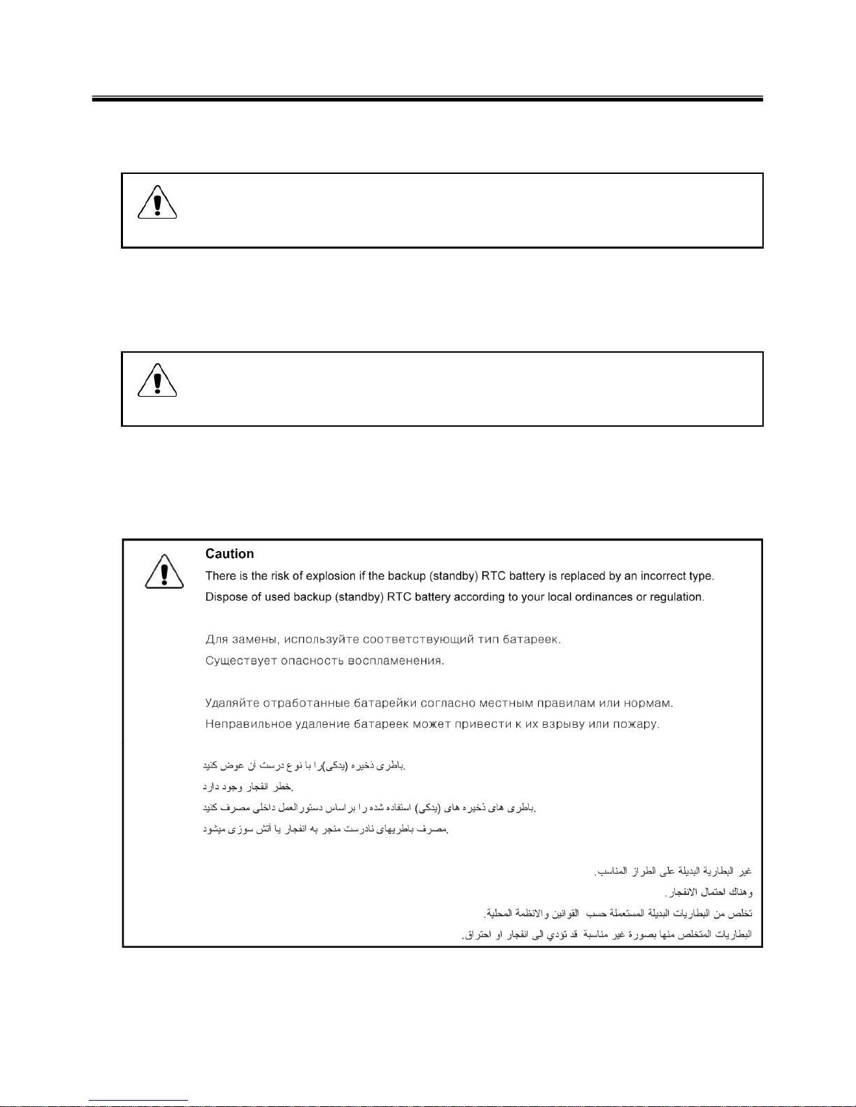
1-5. Backup (Standby) RTC battery safety information
When replacing or disposing of the backup (standby) RTC battery, note the following :
Ch1. Service information

11
1-6. Read this first
Before you go to the checkout guide, be sure to read this section.
Important Notes
· Only trained personnel certified by LG should service the computer.
· Read the entire FRU removal and replacement page before replacing any FRU.
· Use new nylon-coated screws when you replace FRUs.
· Be extremely careful during such write operations as copying, saving, formatting.
Drives in the computer that you are servicing sequence might have been altered. If you selected an
incorrect drive, data or programs might be overwritten.
· Replace FRUs only for the correct mode.
· When you replace a FRU, make sure the model of the machine and the FRU part number are correct by
referring to the FRU parts list.
· A FRU should not be replaced because of a single, irreproducible failure. Single failures can occur for a
variety of reasons that have nothing to do with a hard ware defect, such as cosmic radiation,
electrostatic discharge, or software errors.
· Consider replacing a FRU only when a problem recurs. If you suspect that a FRU is defective, clear the
error log and run the test again. If the error does not recur, do not replace the FRU.
· Be careful not to replace a non-defective FRU.
What to do first
You must fill out the record form first.
During the warranty period, the customer may be responsible for repair costs if the computer damage was
caused by misuse, accident, modification, unsuitable physical or operating environment, or improper
maintenance by the customer. The following list provides some common items that are not covered under
warranty and some symptoms that might indicate that the system was subjected to stress beyond normal
use. Before checking problems with computer, determine whether the damage is covered under the
warranty by referring to the following :
Ch1. Service information

12
The followings are not covered under warranty :
· CD panel cracked from the application of excessive force or from being dropped
· Scratched (cosmetic) parts
· Distortion, deformation, or discoloration of th e cosmetic p arts
· Cracked or broken plastic parts, broken latches, broken pins, or broken connectors caused by excessive
force
· Damage caused by liquid spilled into system
· Damage caused by improper insertion of a PC Card or the installation of an incompatible card
· Damage caused foreign material in the diskette drive
· Diskette drive damage caused by pressure on the diskette drive cover or by the insertion of a diskette
with multiple labels
· Damaged or bent diskette eject button
· Fusses blown by attachment of a non-supported device
· Forgotten computer password (making the computer unusable)
· Sticky keys caused by spilling a liquid onto the keyboard
The following symptoms might indicate damag e caused by non-warranted activitie s :
· Missing parts might be a symptom of unauthorized service or modification.
· If the spindle of a hard-disk drive becomes noisy, it may have been subjected to excessive force, or
dropped.
Ch1. Service information
13
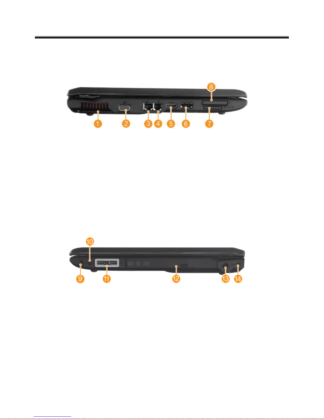
1. Fan louvers
2. VGA Port
3. LAN Port
4. Modem Port
5. HDMI Port
6. e-SATA Port(USB-combo)
7. Multi Card Slot(xD/SD/MS/MS Pro)
8. Express Card Slot
9. Microphone Port
10. Headphone Port
11. USB Port
12. Optical Disk Drive
13. Power Port
14. Kensington lock
Chapter 2. Locations
Ch2. Locations
■ Left View
■ Right View
14
Ch2. Locations
①
②
③
④
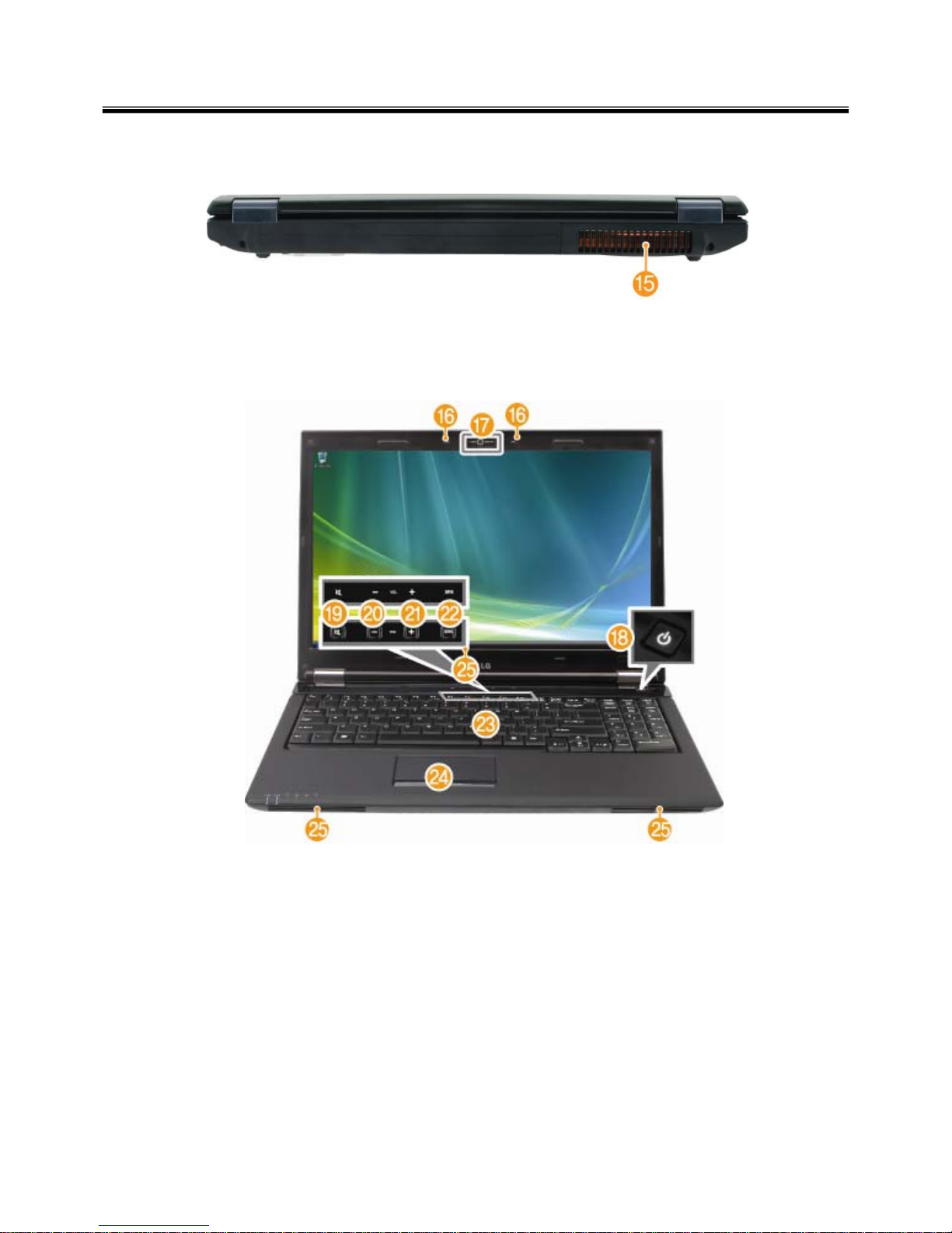
16. Built-in Microphone(May vary depending on model.)
17. Smart Cam(May vary depending on model.)
18. Power Button
19. Mute Button
20. Volume Down Button
21. Volume Up Button
22. SRS Button
23. Keyboard
24. Touchpad
25. Stereo speaker
■ Front Back
■ Front View
15. Fan louvers

15
Chapter 3. System information
Specification
Ch3. System information
- Available Processors
· Intel® Core™2 Duo / Pentium® Dual‐Core / Celeron® Dual‐Core / Celeron® Processors (L2 Cache Size:
1MB/2MB/3MB/6MB, FSB:667/800/1066MHZ ) are supported.
The user must not replace or expand the CPU capacity arbitrarily. The CPU capacity differs depends on
model type.
-Main Memory
· Maximum Capacity: Each slot is 2048MB and can be expanded to 4096MB.
· SO DIMM Type for Memory Expansion: DDR2/DDR3 SDRAM SO-DIMM(256MB, 512MB, 1024MB, 2048MB)
To use two 2GB memory cards, the machine must run on 64bit OS. 32bit Vista/XP OS does not support 4GB
memory.
32bit Windows Vista/XP OS does not support 4GB memory.
When you use two memory slots, make sure to use the memory from the same company.
- Secondary Storage Devices
· 2.5" Hard Disk Drive (SATA)
※
The hard disk capacity and the type depend on the notebook PC model.
-LCD
· 15.6" HD+ (1600 x 900) w/LED Backlight TFT Color LCD
· 15.6" HD (1366 x 768) w/LED Backlight TFT Color LCD
Some models are equipped with the Glare
‐
type LCD featuring enhanced sharpness. This type of LCD
appears to glare more than other types, but it is a normal phenomenon in the Glare type.
※
The size and the resolution rate of the LCD depend on the notebook PC model.
- Authentication for Anticopy Technology
· U.S Patent Nos.4,631,603;4,577,216;4,819,908;4,907,093;5,315,448;and 6,516,132. Patent number of
Macrovision.
This product includes the technologies that are possessed by Macrovision and corresponding companies
and protected by the US Patent Law and other related laws. Use of all technologies subject to the copyrig
ts must be approved by Macrovision in advance. Otherwise, the technologies may only be used for intern
al display. Do not disassemble or remodel the product.
- Bluetooth
· Qcom, QBT400UB
· Ver2.0 Bluetooth Module
※
Bluetooth is optional, and so it may not be installed in some models.

16
Chapter 3. System information
-Web Camera
· 1.3 Mega pixels USB camera module
· UVC (USB Video Class) driver supported
※ Web Camera is optional, and so it may not be installed in some models
- External I/O Interface
· External VGA Monitor Port: 1
· Microphone: 2
· Microphone Input Port (Mic in): 1
· Headphone Port: 1
· HDMI Port: 1
· USB 2.0 Ports: 3
· Multi-card Slot: 1
· Express Card Slot: 1
· RJ 45 (LAN) Port: 1
· RJ 11 (Modem) Port: 1
· e-SATA (USB Combo) Port: 1
※
The support availability may differ by model type.
-Video
· NVIDIA Geforce GT 105M w/512MB or GT 130M w/1GB with TurboCache 576MB ~ 2815MB
TurboCache - This technology actively utilizes part of the System Memory when processing large graphic
data like 3D graphics. The size of the utilized memory is determined by the Video Memory size and System
Memory Sizes.
If TurboCache technology is applied to the Graphics Memory, the System Memory can allot up to 576MB out
of 512MB and up to 2815MB out of 4096MB for large graphic data.
※
The specifications may differ depending on the model type and the video driver.
- Sound
· Realtek High Definition Audio Codec (ALC262) HDMI is supported
· Built-in Stereo Speakers
-LAN
· Realtek RTL8103/8111 10/100/1000 PCI Express Fast Ethernet Controller
· RJ 45 Jack
※
Specifications may differ by model type.
- Wireless LAN
· Ralink RT2700E / Intel 512AN_MMW / 533AN_MMW
※
Wireless LAN specifications may differ by model type and cannot be arbitrarily changed by the user.
- Weight
· Full Installation: About 2.7kg
· Battery: About 320g
※
Weight descriptions may differ by model type.
17
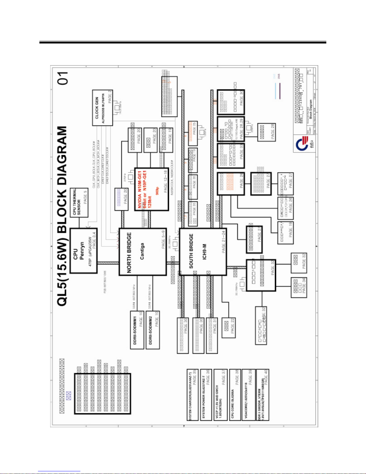
■ System Block Diagram
Chapter 3. System information

18
Fn key combinations
The following table shows the function of each combination of Fn with a function key.
Function of Fn keys has nothing to do with Operating System.
Chapter 3. System information
Fn + F1
Customizable hot keys. (Configurable through OSD settings)
Fn + F2
Customizable hot keys. (Configurable through OSD settings)
Fn + F3
Magnifying hot keys.
Fn + F4
Windows Executes the mode defined in the Power Save Mode. (Example: Standby Mode, Maximum
Power Saving Mode)
Fn + F5
When the user presses Fn + F5 keys, the touchpad mode toggles from Touchpad Disable, to
Touchpad Auto‐Disable (upon connection of external USB mouse), to Touchpad Enable in order.
(Initialization takes 1 ˜ 2 seconds. It is recommended to use after the initialization.)
Fn + F6
Turns the wireless devices (incl. Wireless LAN and Bluetooth) on and off ( Bluetooth is optional, and
so it may not be installed in some models.)
Through hot key settings in the OSD Tray menu, the user can customize [Fn]+[F6] features. Default
setting is, for all wireless devices (incl. Wireless LAN and Bluetooth), ON/Off.
Fn + F7
Monitor toggle. If you have an external monitor connected to the computer, press Fn + F7 keys to
rotate the display mode from LCD only to Monitor only, to LCD + Monitor both in order.
Fn + F8
Switches between the SRS Off, SRS WOW HD, SRS TruSurround XT modes for each pressing the
Fn + F8 keys
Fn + F9
Mute (Sound ON / Sound OFF)
Fn + F10
System Information. System summary information will be displayed.
Fn + ▲
Increases LCD brightness, which can have eight different levels.
Fn + ▼
Decreases LCD brightness, which can have eight different levels.
Fn + ◀
Turns down the volume.
Fn + ▶
Turns up the volume.
Fn + F11
Fan Control feature. Switches the cooling fan mode between Normal and Silent for each pressing.
Fn + F12
Hibernates (When OSD is installed)
Fn + NumLk
Turns the numeric keypad on and off.
“・Delete key types “·” when Num Lock is enabled, and works as a "Delete" key when Num Lock
is disabled.
19
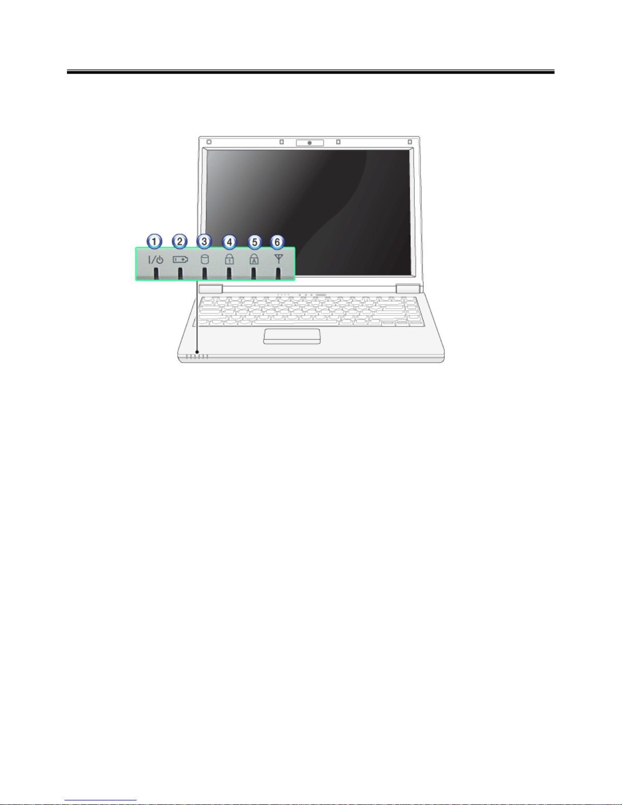
The system status indicators show the status of the computer
1 . Power Lamp:
• Blinking: System Standby
• On: The system is running on the AC power or battery.
• Off: The system is turned off or in Hibernates.
2. AC Power and Battery Status Lamp
• Orange: The battery is being charged.
• Orange/Green Blinking: Charged more than 90%
• Off: The AC adapter is not connected and the battery is being discharged.
• Green: The AC adapter is connected and the battery is not in charging stage, or the battery is fully
charged.
• Green Blinking: The battery is being discharged,, and the battery is running low.
• Red Blinking: In faulty state
• If you try to turn on the system that has entered the Hibernates mode or been turned off after a
low‐battery alarm, the system will not be turned on but the lamp will blink three times.
3. Hard Disk Drive Lamp
• The lamp is turned on when the HDD is running.
※
Do not turn off the power forcibly while the hard disk drive lamp is on. Otherwise, the data may get
impaired. .
4. Num Lock lamp
• You can activate Num Lock feature by pressing the Num Lk key. Then, the NumLock lamp will be turned
on and you can input numbers (0 ˜ 9) using the numeric keypad. Press the Num Lk key again to turn off
the NumLock f e a t ure a n d us e t h e ke ys as the lowe rcase signs including arro ws indicat e.
5. Caps Lock lamp
• Caps Lock lamp is on when the it is active. When this lamp is on, you can type uppercase letters without
holding Shift key.
Status indicators
Ch3. System information

20
Ch3. System information
6 . Wireless LAN/Bluetooth lamp
• Off: Wireless LAN/Bluetooth is not in use.
• Blinking (short interval): Wireless LAN/Bluetooth is connected and data are being transmitted.
• Blinking (every 2 ~ 3 seconds): Wireless LAN/Bluetooth is not connected but Wireless Radio is on.
• Blinking (every 3 ~ 4 seconds): An access Point is being searched for to connect Wireless LAN/Bluetooth.
• On: An access point is being searched for or Wireless LAN/Bluetooth is connected.
※
The Wireless LAN/Bluetooth lamp may operate differently depending on model type.
※
The Wireless LAN card and the Bluetooth device are optional, and so it may not be supported in some
models. .
21
■BIOS Flash
You Can update BIOS using USB Device (FDD/USB Memory)
Because this system is not equipped with any USB Device, you have to use an external USB Device
for a BIOS update.
In order to boot up with an USB Device, please set Removable Device as the
first boot up drive in the boot menu of BIOS Setup.
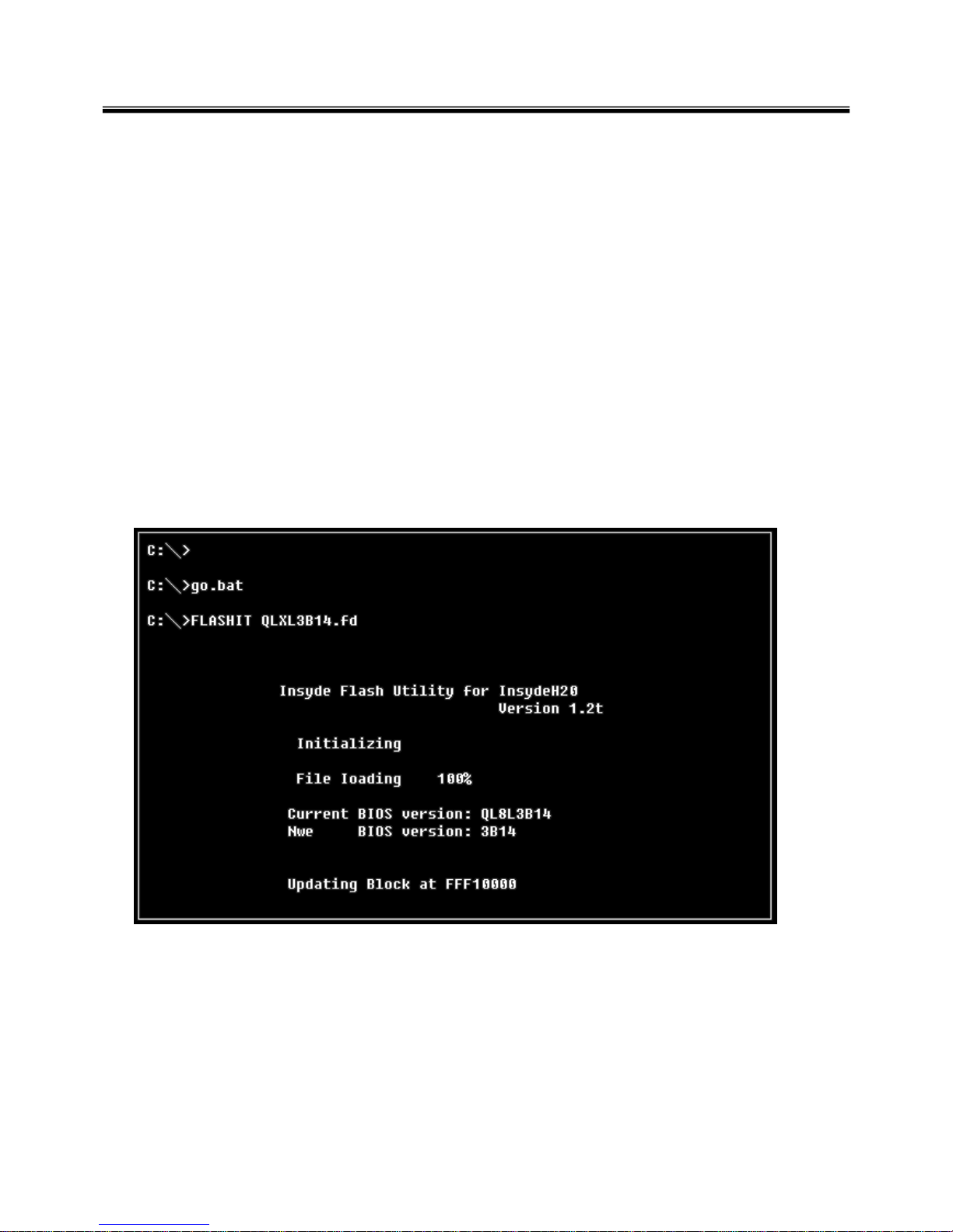
· How to update flash Rom in Dos
1. Create ‘boot up’ flash update USB Device (FDD/USB Memory).
2. Copy BIOS Flash software to the flash update USB Device (FDD/USB Memory).
3. Connect the USB Device for USB Port.
4. Press F12 Key while the "LG LOGO" appears.
5. A while later, the system setup home screen appears.
6. Type in “go.bat ”. (x_xxx is Model Name & BIOS version)
7. You can see the BIOS flash process as below.
Ch3. System information
8. After flashing is completed, The comp uter turn off with automatic movement. .
22
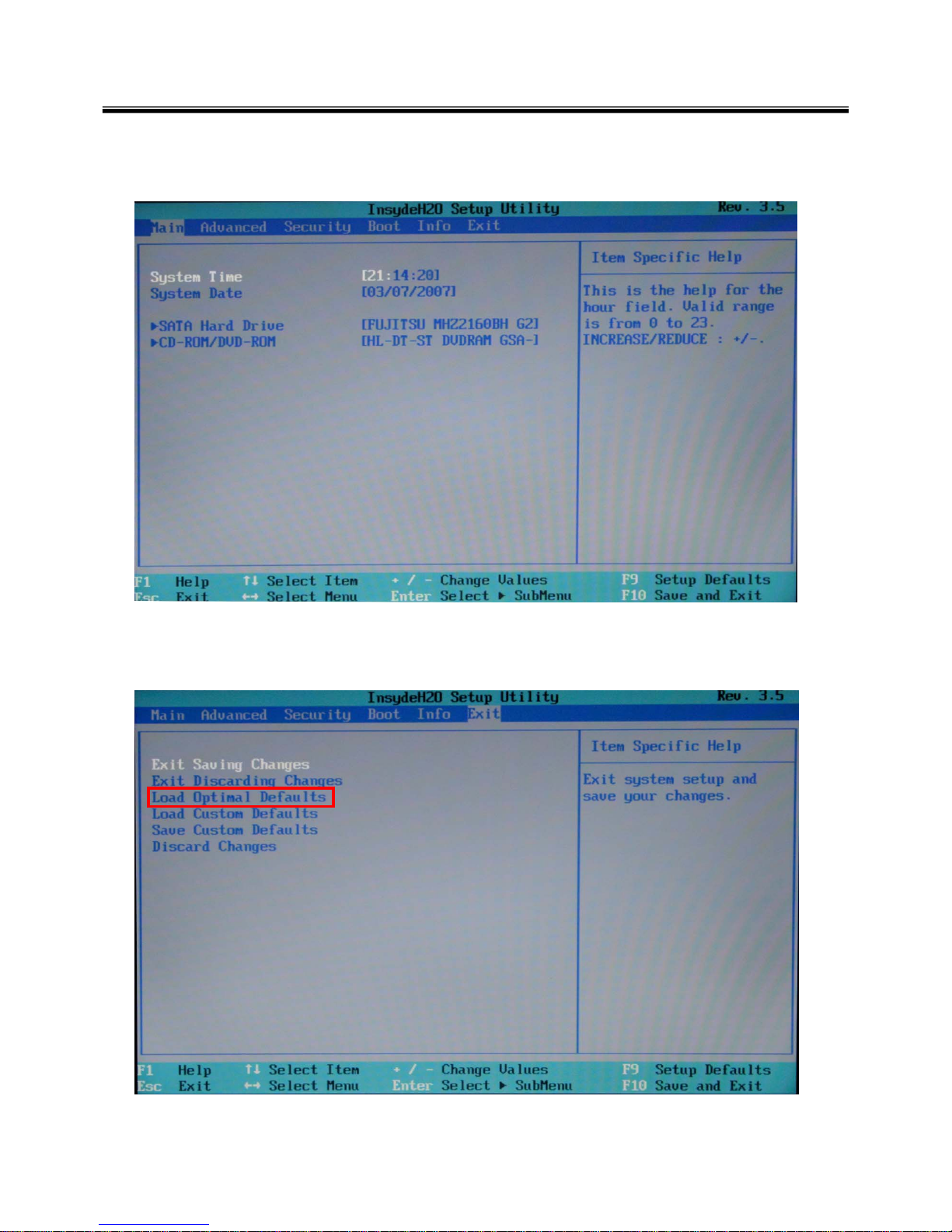
10. Press [F2] Key, then you can see the BIOS SETUP UTILITY screen as below.
11. It selects the :” Load Optimal Dafault” and it summons a BIOS settings at initial value.
Ch3. System information
23
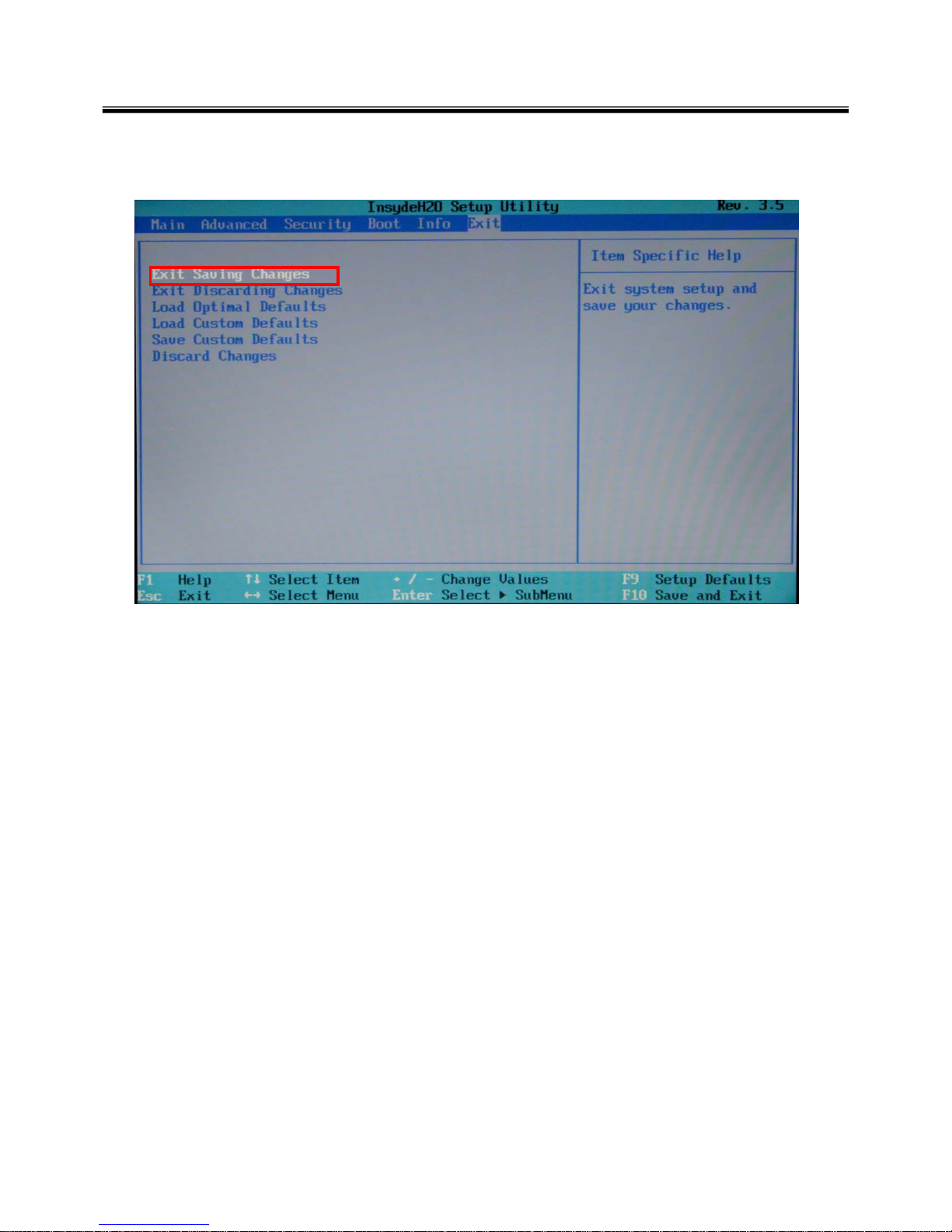
12. It selects the “Exit & Saving Change” and it stores system a settings and the reboot
Ch3. System information
24
Ch3. System information
BIOS Release Process and Making Bootable CD
1. LGE(Korea) will upload BIOS Image(*.iso) to GCSC(Global Cyber Service Center:http://biz.lgservice.com)
when BIOS should be updated.
2. BIOS will include both System BIOS and EC(Embedded Controller) BIOS.
3. Service center can download BIOS file from GCSC and update BIOS according to below procedure.
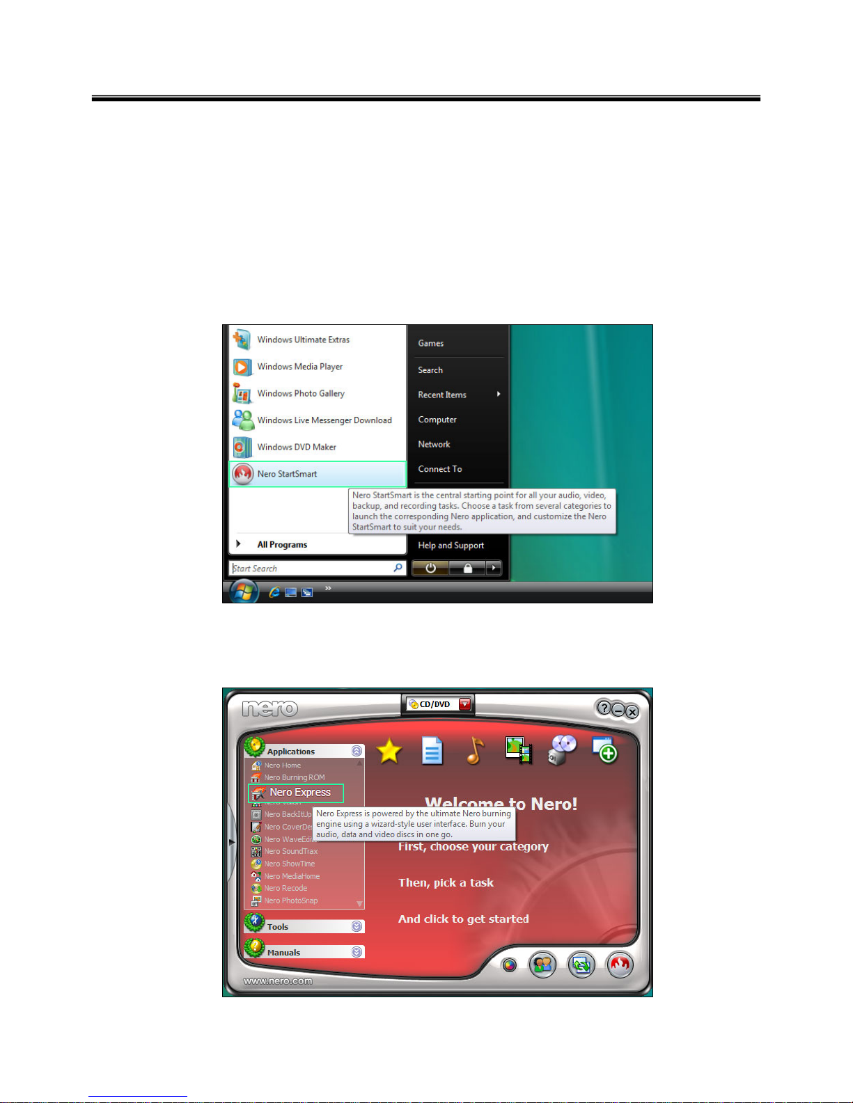
4. Service center will make Bootable Image CD with Image file(*.iso) as below
a. Insert empty disc to CD-RW Drive and start Nero “StartSmart”.
b. Select “Nero Express”.
25
Ch3. System information
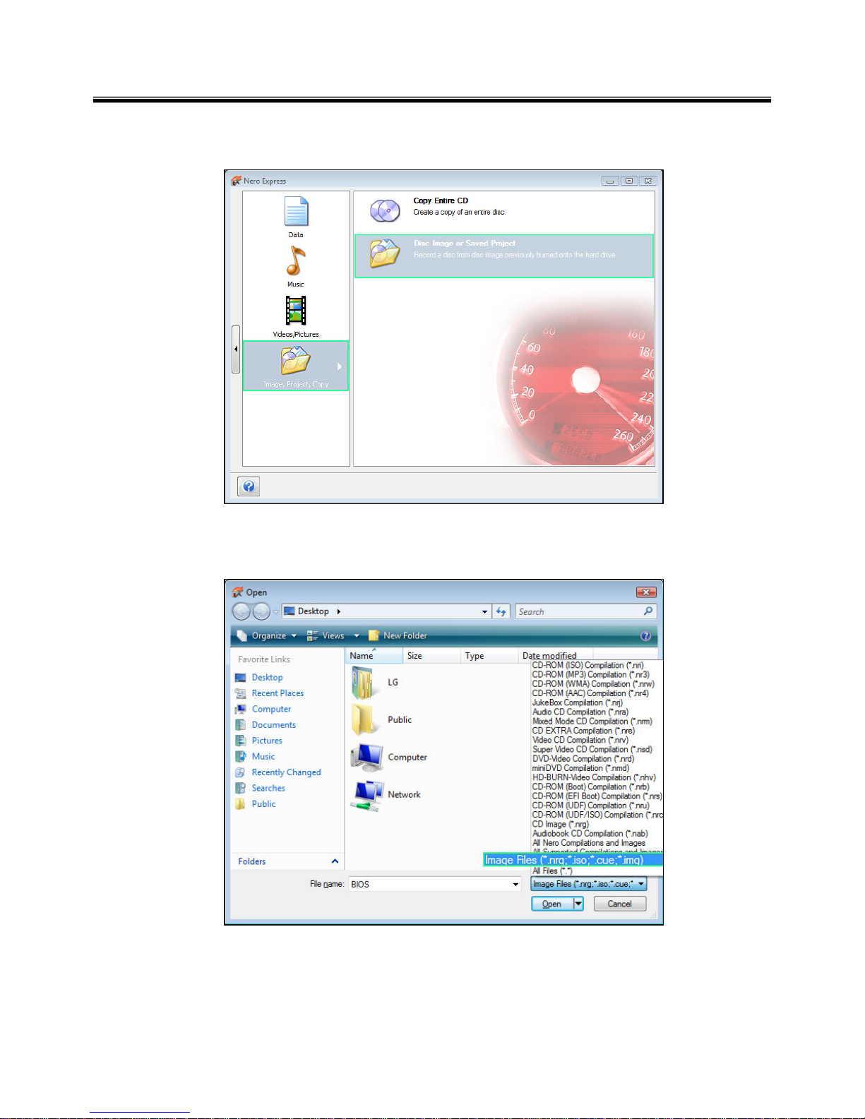
c. Select “Disc Image or Saved Project”
d. Select File Format as "Image Files(*.iso)".
26
Ch3. System information
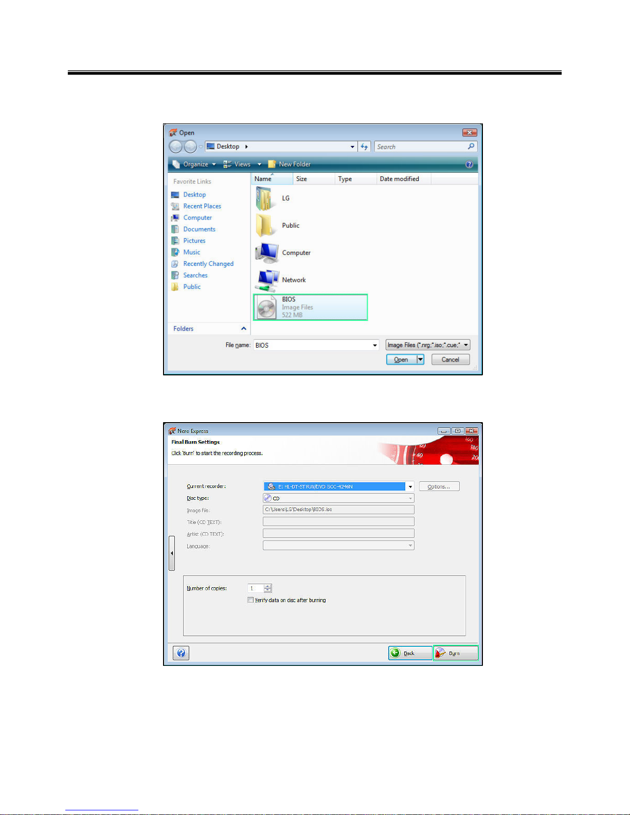
e. Open Image File(*.iso) which is sent from LGE
f. Tab Burn then burning will be started
27
Ch3. System information
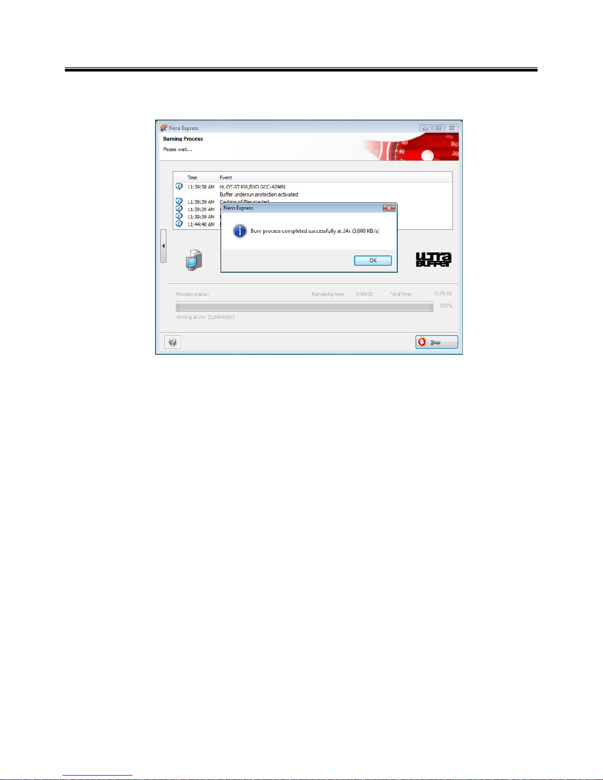
g. Burn process completed as below, and tab “OK
28
Ch3. System information
BIOS/EC Flash Process
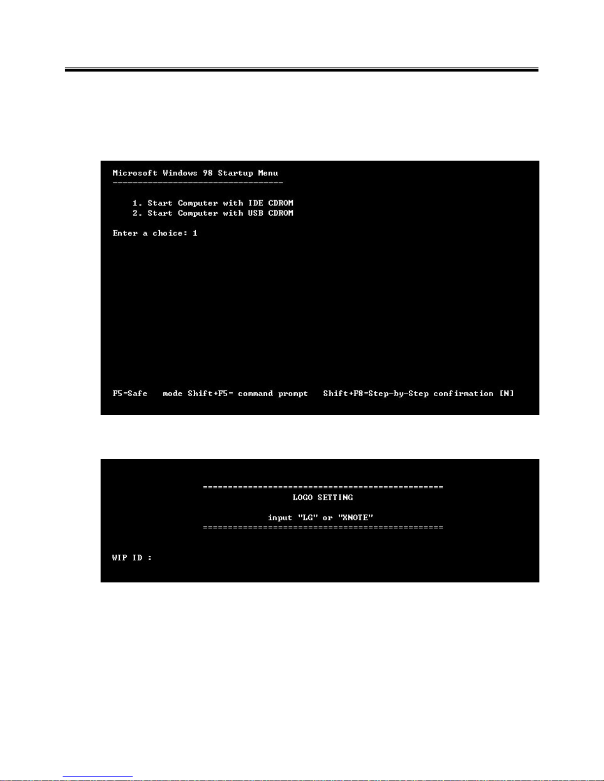
1. Insert Bootable CD in PC, and Turn it on, then PC will boot by DOS mode as below
(If the EC is not correct or old version, then automatically update EC first and reboot again)
2. Select Boot mode, then press “Enter” Key.
3. Type in LOGO SETTING at the “WIP ID :” then press Enter key (You must use Capital Letter)
29
Ch3. System information
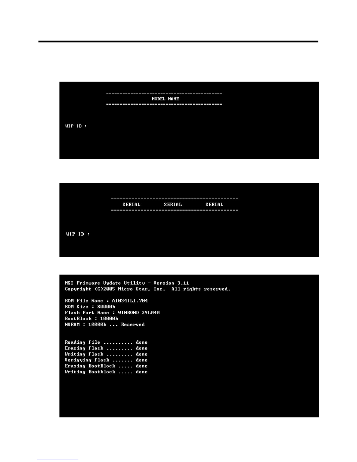
4. Type in Mode Name at the “WIP ID :” then press Enter key (You must use Capital Letter)
(You can see the Model Name in ID Label at the bottom Case of PC: “M/N: LMXX-XXXX”)
5. Type in Serial No at the “WIP ID :” then press Enter key (You must use Capital Letter)
(You can see the Serial No in ID Label at the bottom Case of PC: “S/N: 412KIXXXXXXXX”(13digits))
6. You can see the BIOS flash process as below

30
Ch3. System information
5. After flashing is completed, you can see the “PASS” on your screen, and reboot your PC
 Loading...