

Page 1

삼 흥
정 판
Website http://biz.lgservice.com
AIR PURIFIER
SERVICE MANUAL
MODEL: PS-N550WP
CAUTION
BEFORE SERVICING THE UNIT, READ THE SAFETY PRECAUTIONS IN THIS
MANUAL.
P/NO : MFL31520605
February, 2007
Printed in Korea
Page 2

CONTENTS
CONTENTS
SECTION
1
PAGE 3~5
SECTION
2
PAGE 6
SECTION
3
PAGE 7
SECTION
4
PAGE 8~16
SECTION
5
PAGE 17~24
Safety instructions
Logics
Major Specifications of each
Model
Operations/Functions Manual
Main Components
Disassemble/Assemble and
Repair Instruction
SECTION
6
PAGE 25
SECTION
7
PAGE 26~30
SECTION
8
PAGE 31~33
SECTION
9
PAGE 34~36
Electric diagram
Troubleshooting and inspection
direction
PCB Circuit Diagram/Parts
Layout
Exploed View/
Svc Components inventory
-2-
Page 3
1
For your safety, the information in this manual must be followed to minimize the risk of fire or explosion, electric
shock, or to prevent property damage, personal injury, or death.
Safety instructions
Warning / Caution
Warning :
Caution :
This symbol will alert you to hazards or unsafe practices which could cause bodily injury or
property damage.
This symbol will alert you to the possibility of improper use that may result in damage.
Read instructions to avoid damage or injury.
Warning
When Installation
If the power cord becomes worn or damaged, the cord should only be replaced by a qualified service technician
using genuine replacement parts.
Do not plug other appliances into the same outlet. Overloading of any outlet can cause a fire or create an electrical
shock hazard.
Do not remove the round grounding prong from the plug.
Do not operate this or any electrical appliance when you smell gas.
Do not operate with wet hands or in a damp environment.
Do not disassemble or modify the air purifier or the power cord.
Do not use this or any appliance near flammable gases or liquids or other combustibles, such as gasoline, benzene,
thinner, etc.
If you hear abnormal sounds or smell smoke, immediately unplug your Air Purifier and have the unit checked by a
qualified technician.
Make sure the Air Purifier and cord is positioned where it does not create a tripping hazard. Do not roll heavy
furniture over the top of the cord.
Do not use near open flames.
Keep this product out of the direct rays of the sun or other heat sources. Do not use the unit near water sources that could allow
moisture to enter the unit. Overheating and/or water infiltration could lead to a fire or shock hazard and could result in failure of the
product.
-3-
Page 4

1
Safety instructions
In-Use
Make sure the power cord is plugged firmly and completely into the outlet.
Do not operate with wet hands.
If the power cord ever becomes frayed or damaged, do not attempt to repair. The cord should be replaced by a
qualified technician.
Never pull the power plug away from outlet by pulling on the wire. Always grasp the cord by the receptacle end.
Do not install a place where there are much industrial Oil dust or metallic dust.
If may cause fire and failure of product.
When the power code is damaged, it should be repaired by the qualified person to prevent any risk.
It may cause electric shock, fire or failure of product.
Never pour or allow water to run onto or into the unit; it could damage internal components and create a shock
and fire hazard.
Keep objects such as curtains away from the air openings in the unit. The openings must be free from
obstruction for the unit to work efficiently.
Do not run power cords under carpeting or other coverings which could fray the cord and expose the wires.
Frayed cords are a shock and fire hazard.
Do not place the power cord or Air Purifier near a heater, radiator, or other heat source.
This air purifier is not designed for use by young children. Young children should be supervised to ensure that
they do not play with or climb on the air purifier.
Do not use your Air Purifier to remove hair spray and insecticides from a room. These chemicals not only clog
the filters but could damage the unit.
Secure the air purifier to prevent it from rolling on smooth floors. When moving the product, insure that the
power cord is unplugged from the wall.
Do not move the air purifier by pulling or pushing on the front panel.
Do not use the top of the unit for storage. Keep liquids away from the top of the unit.
Other than cleaning and replacing the filters, there are no user replaceable components in your Air Purifier.
Service of this unit should be referred to a qualified service technician.
Do not apply pressure to the front panel of the air purifier.
Keep hands and objects away from the air inlet and outlet.
Do not clean the unit by submerging in water. Water in the unit will damage the insulation and create an
electrical shock hazard. If water enters the unit, unplug immediately and contact Customer Service.
-4-
Page 5
1
Safety instructions
Caution
When Installation
When using the unit, maintain a distance of at least 3 feet between the Air Purifier and any Television or audio
product.
Avoid installing the Air Purifier in direct sunlight and never operate the unit near or around open flames or other
heat sources.
Never use your Air Purifier to remove toxic gasses (such as Carbon Monoxide, Natural or Liquified Petroleum
Gasses).
Do not use your Air Purifier to remove food odors while cooking. Airborne oils that are released during cooking will plug the
filters. Wait until cooking is completed before operating your Air Purifier.
Install the unit on a stable, flat surface. Do not drop the unit.
Maintain a minimum distance of 5 ft from any heat producing light source. For proper ventilation, maintain a
distance of 6 inches or more from a wall.
Do not use except AC 120V.
It may cause fire or electrical shock.
This unit is not designed to remove combustion by-products such as those produced by open flame burners.
Toxic substances such as carbon monoxide should be ventilated from the room by either using an exhaust fan or
by opening a window.
Your air purifier is not designed to be used in moving vehicles such as cars, RV's or boats.
In-Use
To prevent damage to plants or injury to pets, make sure they are not exposed to direct air flow from the air purifier. This unit is
not intended to be used for the preservation of art objects or precision machinery.
Clean with a soft cloth and mild detergent. Filter should be cleaned once a month.
Do not start or stop operation by plugging in or unplugging the power cord.
Always turn off and unplug the air purifier when it will not be used for extended periods of time. This conserves energy and
reduces the chance of accidents.
Clean filters on a regular basis. Improper filter maintenance can cause premature failure of the product.
Turn off and unplug the unit before disassembling the unit for cleaning.
A damaged filter can create an electrical hazard.
If a humidifier is used in the same room as your Air Purifier, keep the humidifier a safe distance away from the Air
Purifier. Moisture from the humidifier could clog the filters and create an electrical shock hazard.
Do not use your Air Purifier to remove food odors while cooking. Airborne oils that are released during cooking will plug the
filters. Wait until cooking is completed before operating your Air Purifier.
Do not open the front panel during the operation of the product.
Opening the front panel stops the operation.
Keep batteries out of reach of children.
After washing your filters, make sure they are completely dry before reinserting them into the Air Purifier. Do not run
your Air Purifier with wet filters.
Keep flammable products away from your Air Purifier. Failure to keep flammable products away from your purifier
could lead to premature failure or create a fire hazard.
-5-
Page 6

2
Logics
Terminology
1-1. Negative ion
(1) What is a negative ion?
Atomic element in the air with negative electrons
that releases a refreshing feeling. It can be found
in a forest, waterfalls, thermal spring and etc. If
the atom loses an electron, it turns into a positive
ion. If the atom gains an electron, it turns into an
negative ion.
(2) The platinum three-dimensional anti-
bacteria system.
99.9% highly purified platinum catalyst filter
completely removes those factors which could
cause the sickhouse syndrome such as VOCs,
harmful chemical element and its smell.
1-2. VOCs (Volatile organic
compounds)
(1) What is VOCs?
Carcinogenic substances that cause allergies or
respiratory ailments, such as a paint, adhesives,
spray, construction materials, wax, carpet, and
etc. Unlike the general perception that only cheap
construction materials emit VOCs, high quality
new constructions may also emit VOCs. It may
stay remained in a closet or inside of furniture
even after several years.
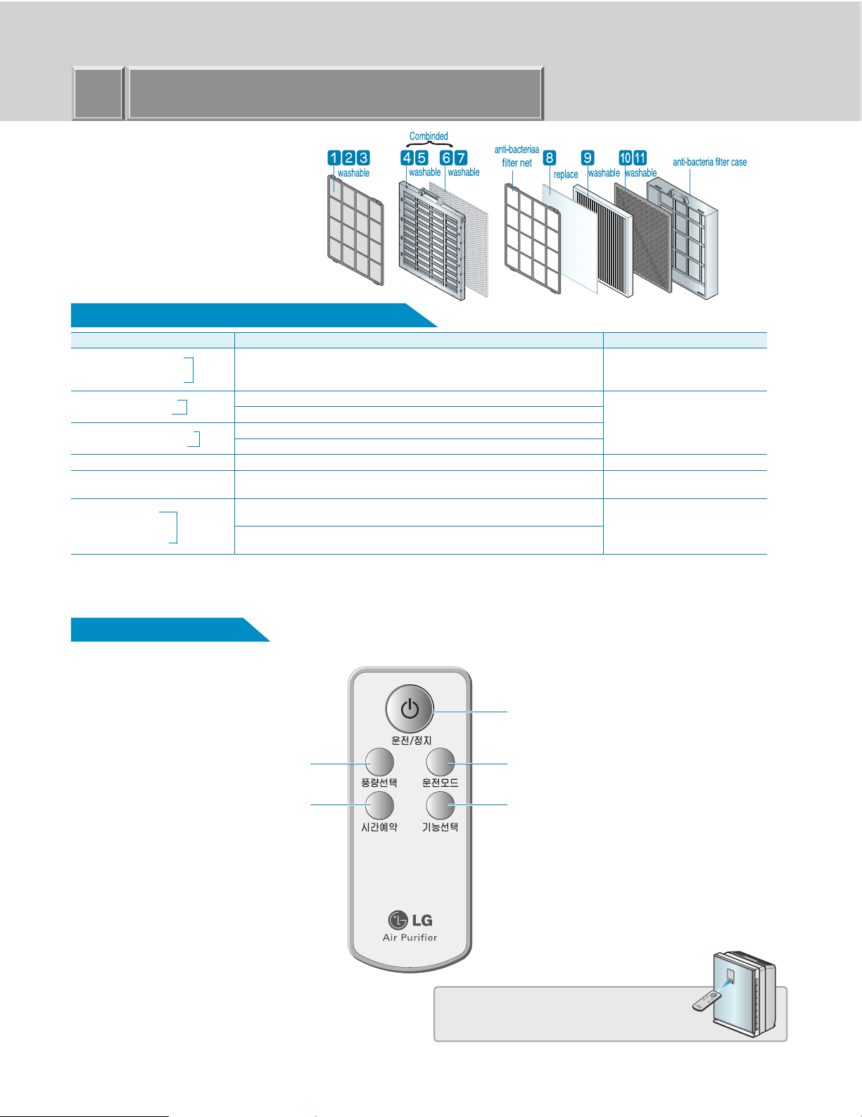
Filters Introduction
(1) Pre-Filter
One filter performs antibiotic treatment, anti mold
treatment, and dust removal, providing a purified
air.
(2) Photo-Catalyst Plasma Filter
Photo-Catalyst Plasma Filter removes
microscopic motes, odor, yellow-dusts, and
allergy causing substance through a 3 stage
process, plasma generation part, dust collecting
part, and photo-catalyst filter
(3) Anti-allergic Filter.
The anti-allergic filter could absorbs and
decomposes the ingredients which causes the
allergy, having the allergy preventive effect also
removing the odor and anti-bacteria effect.
(4) Washable HEPA Filter
HEPA filter polluted by acarid deadbody, pollen,
small dust and float mildew, animal bodyhair etc.
can be washed.
(5) Washable Deodorization Filter
This filter was processed with activation treatment
for stronger adsorption function (characteristic of
charcoal). This deodorization filter has higher
level of negative ion, minerals, far infrared lays
generation ability than charcoal.
-6-
Page 7
3
Major specifications on each model
Model name
Power Supply
Measurement(W×H×D)
Application Space
Weight
Color
Design
Power usage
Noise
Wind speed(CMM)
Negative ion Generation
Inhale system
Purifying system
Major Filter System
Filter composition
PS-N550WPR
120V~60Hz
426mm×568mm×271mm
2
45m
12.0kg
Red
Easy design for convenient operation
55W(Turbo)
Turbo(47dB)
Turbo(6.4CMM)
Generate 1million super negative ions
side surface inhale system
Three dimension filter system
Pre-filter - Anti-allergic filter - Washable HEPA Filter -
Super Negative ion/ Sterilization
Washable part - Replacement part
Remote controller
Sensor
Display
Display Information
Operation Mode
Function Selection
Wind Speed
Ez remote controller
Digital 2 Sensor(dust, smell)
Digital Wide LED display
Dust, Smell, Purity level, Fan speed, Filter Checking, Function
Selection, Operation Mode, Reservation time
Speed, Automatic, Yellow Sandstorm, Sleeping
Negative ion, Sterilization
Turbo-Strong-Soft-Weak
-7-
Page 8
4
Operations/Functions Manual
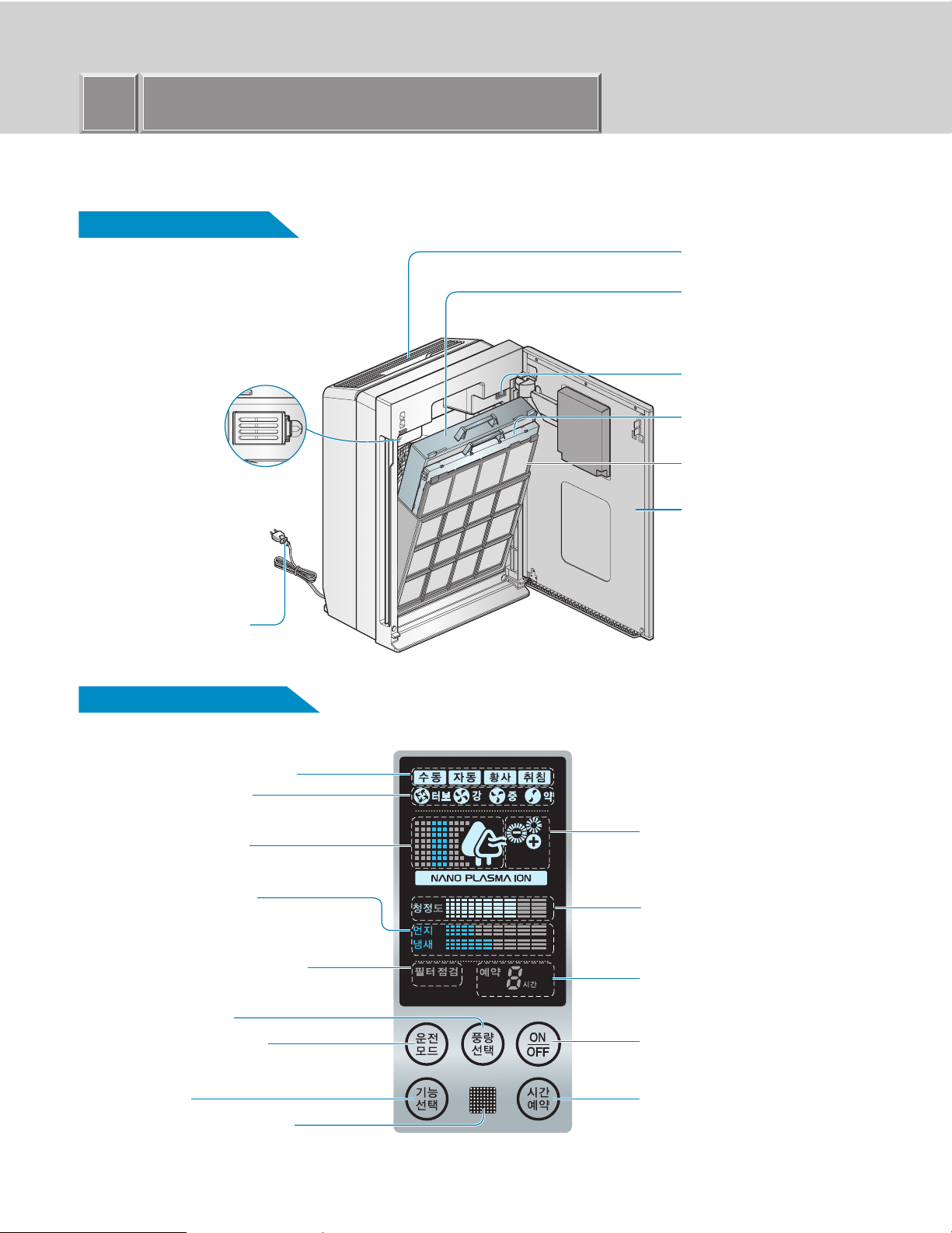
Spare part Name
Mainframe
Safty Net:
The inside of air outlet
Filter case
(Allergen filter + HEPA filter +
deodorizing filter)
Odor sensor
Dust Sensor
Power Plug
Display and controller
Operation mode indicator
Fan speed indicator
Operation indicator
Photo-Catalyst Plasma Filter
Pre-filter
Front panel
Negative ion/ sterilization
indicator
Dust/Odor indicator
Reflects how well air is moving through
the unit.
Filter self-checking indicator
Check the filter when indicated by the light.
Fan speed button
Operation mode button
ION button
Remote controller receiver
Purity level indicator
Level reflects how well the air purifier is
cleaning the air.
Time reservation display
Power On/Off button
Off timer button
-8-
Page 9
4
Operations/Functions Manual
Filter system (include the filter part only)
Filter name Function
Removes large particles
Anti-bacteria function
Anti- mildew function
Plasma dust-absorb filter
Plasma deodorant filter
Photo-catalyst anti-bacteria filter
Photo-catalyst deodorant filter
Anti-allergic filter
Washable HEPA filter
Washable carbon
Catalyst function
Nano Platinum filter
Allow the filter to dry completely before reinstalling. If not completely dried, it may cause the air purifier to malfunction or cause bad odors to be emitted during use.
※
A replacement filter (Anti-Allergic Filter) can be purchased at an LG service center.
※
Pre-filter
Plasma filter
Washable
deodorization
filter
This filter has anti-bacteria, anti-mildew, and large particle filtering functions.
In extreme filtering conditions, these filters may have to be cleaned or
replaced more often.
Filters large particles such as pollen, soot, and mildew.
Absorbs odors and dust.
Photo-
Additional odor absorption and large particle filtering.
catalyst
Remove odor particles, VOCs, smoke smell, musty smell, decompose malodor ingredients and chemicals.
filter
Absorbs and eliminates allergens.
Washable HEPA filter removes pollens, dirt particles, dust and mildew
from the air.
Eliminates food, pet and other odors. Removes alkaline, acid and organic
compound odors.
This filter uses jewelry grade platinum and should be disposed of properly
when discarded.
Washing/Replacement cycle
Once a month
Once a month
6~12 months replacement cycle
Every 6 months
Every 6 months
Remote Controller
Fan speed button
Adjust the timer delay time
Set Fan speed
Off timer button
Power On/Off
Turns the air purifier on and off
Mode
Switches the operation speed, auto mode, sand
mode and sleep timer.
ION button
When turned on, the unit produces negative ions
which can help sterilize the air.
Remote Control
Must be aimed at the remote control receiver window on
the main unit.
-9-
Page 10
4
Operations/Functions Manual
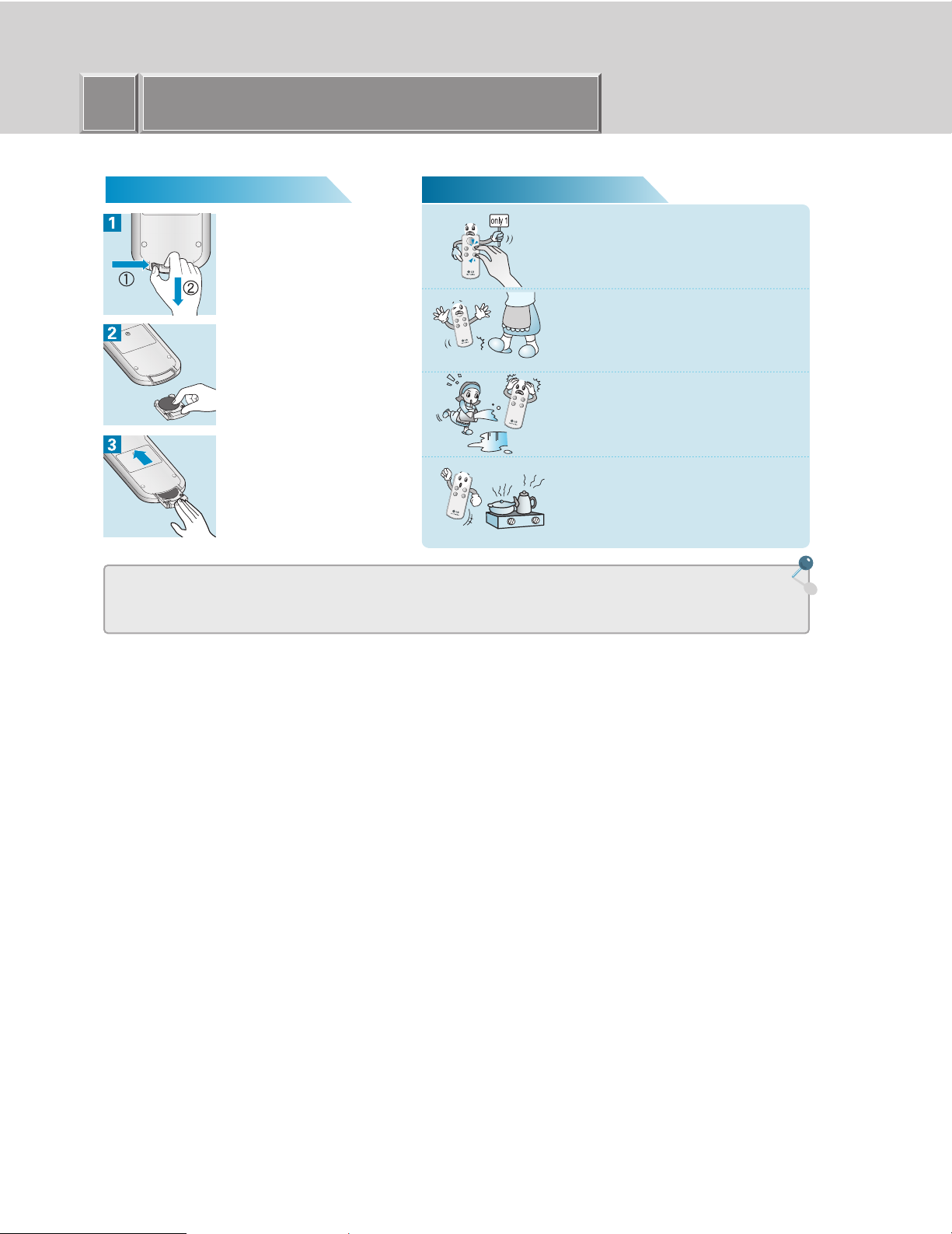
Battery Installation Caution
Press locking tab on the battery
cover on the back of the remote
and remove the cover.
Insert new batteries into the
battery compartment, being sure
to note the proper polarity.
Reattach the battery cover,
making sure the locking tab
clicks into place.
Press only one button on the
remote at one time.
Press only one button on the remote at one time.
Pressing two or more buttons simultaneously will
prevent the remote from working properly.
Do not drop or otherwise damage
the remote.
Keep remote away from water.
Keep remote away from heat
sources or open flames.
• Remove batteries when the air purifier is stored for extended periods of time.
• If controller fails to work after new batteries are installed, contact an LG service center for service.
-10-
Page 11
4
1
1
2
3
1
2
3
1
Operations/Functions Manual
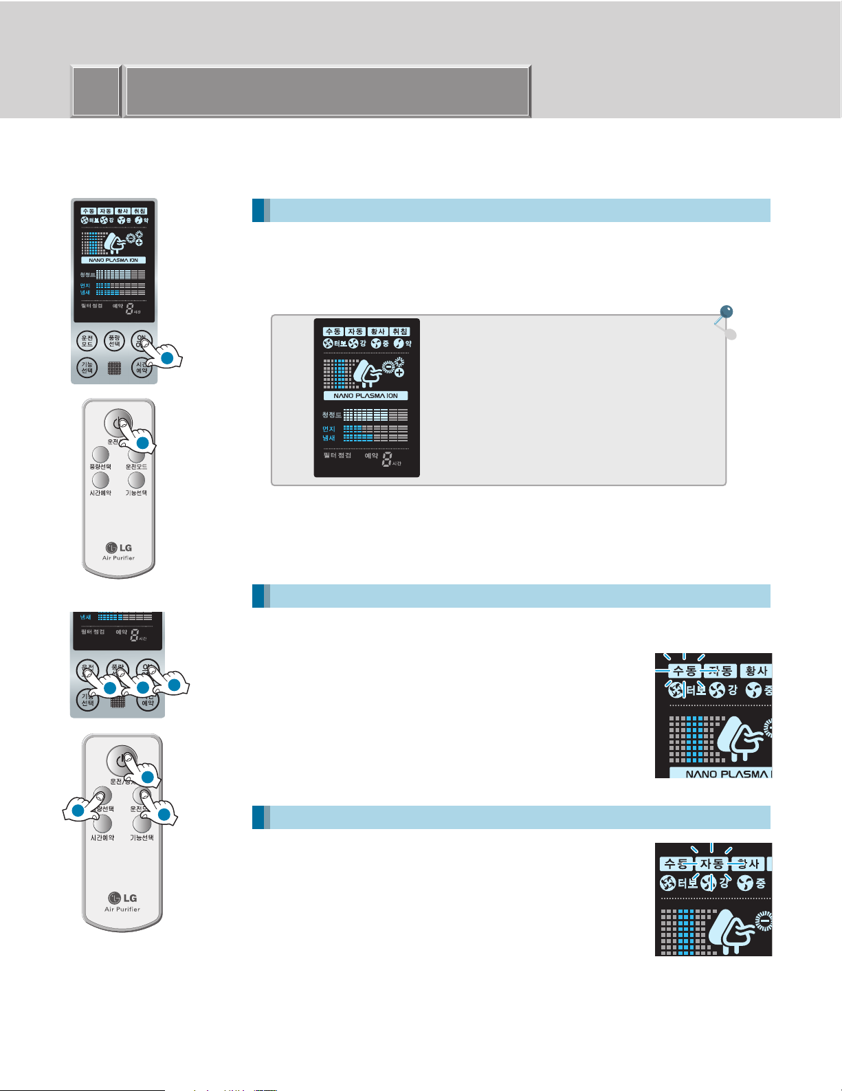
Operation Mode
Air Purifying Operation Purify Indoor Air
Power ON/OFF
Turns the air purifier on and off. Press once to turn on, again to turn it off.
A confirmation tone will sound to indicate that the unit is powering on or turning off.
The unit will also produce a tone when the unit is first plugged in.
What is "Start-up Operation"
When first turned on, the unit will go through
Start-up function which prepares the unit for
operation. During this 2 minute period, the
display will fluctuate to indicate that the unit is
sensing the air quality in the room.
Speed mode User may manually adjust fan speed
Power ON/OFF
MODE switches allows the user to select the
various modes of operation including auto fan
and sleep, sandstorm and self timer modes.
Fan Speed
Adjusts the circulation fan speed between low, medium, high and
turbo.
• The default speed is low.
• When the unit is shut off and restarted, the fan speed will default
to the last fan speed used.
Automatic mode Air Purifier will automatically set the most appropriate Fan speed.
Power ON/OFF
Automatic Mode
• When in AUTO mode, the fan speed is automatically selected by
the unit depending on pollution levels. Even in the AUTO mode,
however, the user can still increase or decrease the fan speed by
one level by depressing the fan speed button.
• The AUTO function only automates the fan speed. All other
functions need to be set by the consumer.
-11-
Page 12

4
2
1
2
1
Operations/Functions Manual
Yellow Sandstorm Mode
Power ON/OFF
Switch to sandstorm mode by pressing the mode
button.
The correct fan speed will automatically be selected by the unit.
The consumer can increase the fan speed to the next highest level
by depressing the fan speed button.
When in the sandstorm mode, the unit will automatically select the
proper fan speed. All other functions must be manually selected by
the consumer.
Sleeping Mode
Power ON/OFF
Press MODE button until the SLEEP light
illuminates on the unit.
When in the SLEEP mode, the unit will automatically select low fan
speed. The consumer can increase the fan speed to the next
highest level by depressing the fan speed button.
Provide quiet indoor atmosphere while sleeping
Purifies indoor air even in extreme conditions such as a sandstorm
-12-
Page 13

4
2
1
2
1
2
1
2
1
Operations/Functions Manual
Additional Function
Off timer mode function
Example:shut down automatically after 3 hours
Power ON/OFF
Allows you to set a delay from 1 to 9 hours that will turn the
air purifier off automatically.
When this mode is selected, the unit will automatically select 3 hours of run time. If
more time is required, press the timer button again. Each time the button is
depressed, the run time will increase by 1 hour. At the end of the selected time, the
unit will automatically shut off.
• Maximum reservation time is 9 hours
• Shut down automatically.
• Automatically shut down 3 hours later.
Automatically shuts down after a preset amount of time
Negative ion / sterilization function
In the Negative Ion mode, the unit generates and adds negative ions to the air stream. When
in the sterilization mode, the negative ions will also remove bacteria from the air.
Power ON/OFF
Press the function button to choose expected function.
• Press button each time, switch according to ‘negative ion - negative ion+sterilization - function abort
- negative ion’ sequence.
-13-
Page 14

4
1
1
Operations/Functions Manual
Filter Checking Function
Filter self check light indicates to check filter.
Power ON/OFF to shut the unit off.
Open front panel to remove filter. Check filter, clean if necessary.
(see page 15 to clean filter).
• How often filter must be cleaned will depend on use and air conditions in the home.
May remind users to clean or replace the filter after use for a certain period.
Exterior Cleaning Method
Wipe the exterior of the air purifier with a soft cloth with warm water and mild detergent.
• Do not use harsh cleaners or very hot water. Do not wash in dishwasher.
Caution
• Never pour water onto the unit; it could damage internal components and
create a shock and fire hazard.
Dust sensor cleaning method
The dust sensor senses both small and large dust particles. The sensor needs to be wiped clean to
maintain high performance.
Open the front panel to access the the dust sensor cover.
Open the dust sensor cover.
Wipe the sensor lens of with a cotton swab.
After cleaning the lens, close the cover of the dust sensor in the reverse order.
Clean the sensor lens every 6 months. If the environment is very dusty, more
frequent cleaning is recommended
-14-
Page 15

4
Operations/Functions Manual
Filter Cleaning
• The prefilter should be cleaned on a monthly basis.
• Check the filter when the filter indicator light is on.
Turn unit off and unplug before cleaning.
Grasp the grips on the front panel, pull forward to open.
Remove the filter from the mainframe. Clean or replace.
Clean the pre-filter with a vacuum or soft brush.
Photo Catalyst Plasma Filter Cleaning
Soak the filter in warm water with a mild detergent for 1 hour. Remove
particles from the filter by shaking the water from the filter. Rinse the
filter with warm water. Completely dry the filter before replacing the
filter.
The ionization wire inside of the filter case is fragile. Please clean with care.
Use a soft cloth when cleaning the photo catalyst plasma filter. The filter coating may peel
resulting in reduced performance.
Separate filter case to remove the filter.
HEPA and Deodorizing washable filter. Soak in warm water for an hour. Rinse.
NOTE: The anti allergic filter should NOT be washed. Washing this filter will
reduce its efficiency.
Clean the washable HEPA filter and deodorization filter with warm water and rinse under running
water. Dry filter in a well ventilated room until completely dry.
Filter Type
Pre-Filter
Photo-Catalyst Plasma Filter
Washable HEPA Filter
Washable deodorization Filter
Replace Anti Allergic filter every 6 to 12 months.
• For your safety, turn off and unplug the air purifier before cleaning.
Caution
• Allow the filters to completely dry before using.
• Utilizing the unit before all the filters are completely dry may result in the creation of odors from the unit.
• Replace filter when unable to remove all dirt on the filter.
• Please do not rub the filter in your hands.
Washing Cycle
Once a month
Every 6 months
Every 6 months
• Clean Pre-Filter with vacuum or soft brush and
mild detergent.
• Do not use water over 40 degrees Celcius
(105 degrees F)
• Do not allow Anti Allergic filter to become wet.
-15-
Page 16

4
Operations/Functions Manual
Maintenance
Remove plug from grounded outlet.
Clean and protect the air purifier's mainframe.
Cover the air purifier when storing for an extended period of time.
Clean with a soft cloth and mild detergent.
Exterior case may scratch easily
-16-
Page 17

Major components Disassemble
5
Assemble and Repair instruction
Please read this before you disassemble
Please unplug the power before disassemble.
1. Most components are connected with bolts or mounted on the other parts. Please
disassemble according to the instruction.
2. Please do not disassemble unless it is absolutely necessary. Do not disassemble any part
that is not on the disassemble instruction.
Please unplug the power before disassemble
Replacing a fan, or a motor
1. Please remove 6 screws from the Case Back using
a Screw Driver(+). Take Handle Cover and Back
Cover off.
2. Unscrew bolts using a wrench.
(Turn it counter clockwise.)
-17-
Page 18

Major components Disassemble
5
3. FAN is disassembled by holding and pulling fan.
4. Please remove 3 screws from the Motor Cover
using a Screw Driver(+).
Assemble and Repair instruction
5. Remove the Motor Cover. Take out the Motor.
Please be careful not to damage the Motor wire
when removing the motor.
-18-
Page 19

Major components Disassemble
5
When replacing the display PCB and the touch key
1. Open the door assembly
2. Loosen the screws on the back of the display cover (3
positions)
Disconnect one wire and 2 connectors
When removing the display cover, disconnect a touch
key connector
Assemble and Repair instruction
3. Loosen the screws on the front of the display cover (4
positions)
-19-
Page 20

Major components Disassemble
5
How to replace the tempered glass and the touch
key
1. Open the door assembly
2. Loosen the screw (1 position)
Open the cover and disconnect one wire and 2
connectors
Remove the door assembly by pulling up.
Assemble and Repair instruction
3. Loosen the screws of the 8 positions on the door
assembly.
Remove the upper and lower deco covers.
-20-
Page 21

Major components Disassemble
5
4. Loosen the screws (3 positions).
Remove the plate iron
Remove the deco cover (Top)
Assemble and Repair instruction
5. Remove the side deco by pushing up.
Remove the tempered glass (When removing,
disconnect a connector)
Be careful not to lose the magnet indicated in the
figure.
6. After replacing the tempered glass and the touch key,
assemble them in the reverse order of the disassembly
-21-
Page 22

Major components Disassemble
5
How to replace gas & dust sensor, HVB assembly,
micro switch and cover terminal
1. After disassembling the door assembly, remove the filter.
Loosen the screws of 6 positions
When removing the front case assembly, disconnect the
connectors on positions.
Assemble and Repair instruction
2. Remove the front case assembly.
Replace the necessary parts.
HVB Assembly
Smell sensor
Micro Switch
Dust sensor
Cover Terminal
-22-
Page 23

Major components Disassemble
5
How to replace the guide filter, bracket, and
magnet assembly
1. Loosen the screws of 6 positions on the front case
assembly.
2. When removing the front cover, the guide filter is
removed.
When removing the screws of 2 positions on the front
case, the bracket is removed.
Assemble and Repair instruction
3. Remove the magnet assembly using a screw
driver.
(Be careful not to damage the hook)
-23-
Page 24

Major components Disassemble
5
How to replace the power PCB
1. After disassembling the door assembly, remove the
filter.
Loosen the screws of 6 positions.
Assemble and Repair instruction
2. Loosen the screw (1 position) attached on the control
PCB case using a screw driver.
(Loosen the screws (2 positions) attached on the
power PCB using a screw driver.)
When disconnecting the connector, be careful not to
damage the PCB.
-24-
Page 25

6
Electric diagram
-25-
Page 26

7
Troubleshooting and inspection direction
Please take a look at the panel arrangement and the circuit drawing.
Complete Malfunction
Is input AC voltage
being supplied to both Power
PCB ASM C01 terminals?
YES
Is DC voltage on both Power
PCB ASM C09 terminals 12V?
YES
Are DC PCB ASM and
Power PCB ASM CONECTOR
correctly connected?
YES
Is DC voltage on both
C04 terminals of MAIN
PCB ASM 5V?
NO
NO
NO
NO
• Make sure that power line is plugged in
• Check the fuse in Power PCB ASM FUSE.
• Replace Power PCB ASM
• Check connections between Power
PSB ASM and MAIN PCB ASM.
•
Replace MAIN PCB ASM
YES
Does the Reset alarm occur
when the power is turned on?
YES
Check LED Display soldering
NO
-26-
•
Replace MAIN PCB ASM
Page 27

7
Troubleshooting and inspection direction
LED Display Malfunction
Are MAIN PCB ASM
and Power PCB ASM CONECTOR
correctly connected?
YES
Is voltage on both C01 terminals
of MAIN PCB ASM 12V?
YES
Replace MAIN PCB ASM.
Dust & Odor LED Display blinking
NO
NO
• Check CN-ACDC connection
• Replace Power PCB ASM.
Are MAIN PCB ASM and
Dust Sensor & Gas Sensor CONECTOR
correctly connected?
YES
Is the voltage of CN-GAS
PIN 1.3/CN-DUST PIN 1.3 5V?
YES
Replace MAIN PCB ASM.
NO
NO
-27-
• Check CN-GAS & CN-DUST
connection.
• Replace MAIN PCB ASM.
Page 28

7
Troubleshooting and inspection direction
Fan Malfunction
FAN indicator on LED DISPLAY?
YES
Is the voltage of
POWER PCB CN-MOTOR PIN
1~4 310V?
YES
Is the POWER
PCB ASM CN-MOTOR CONNECTOR
plugged in properly?
YES
Is the CN-ACDC
CONNECTOR of the POWER PCB ASM
and MAIN PCB ASM connected
properly?
NO
NO
NO
NO
• Check FILTER S/W contact
• Replace POWER PCB ASM.
• Check CN-MOTOR connection.
(Check after power-off)
• Check CN-ACDC connection.
YES
Does the Operation shut off
after 30 seconds of running?
YES
Replace PCB ASM.
-28-
Page 29

7
Troubleshooting and inspection direction
Negative Ion/Positive Ion generation malfunction
IS NPI(Negative ion/Positive ion)
Selected?
YES
Are POWER PCB ASM
and MAIN PCB CONECTOR
correctly connected?
YES
Is the power of
POWER PCB ASM CN-ACDC PIN2&8 (Negative Ion)
and PIN2&9 (Positive Ion)
AC220V?
YES
Is the power of POWER PCB ASM
CN-ASEI PIN1& 3 (Negative Ion) and PIN3&5
(Positive Ion) AC220V?
NO
NO
NO
NO
• Select Negative ion/Positive ion.
• Check CN-ACDC connection.
• Replace MAIN PCB ASM.
• Replace POWER PCB ASM.
YES
Are POWER PCB
and NPI MODULE CONECTOR correctly
connected?
YES
Replace NPI MODULE.
NO
-29-
• Check CN-NSEI connection.
Page 30

7
Troubleshooting and inspection direction
Not able to set product function with a remote control.
Does an alarm occur when
you operate the keys on the
remote control?
YES
Is the power of CN-REC 1&2 DC+5V?
YES
Replace MAIN PCB ASM.
Plasma dust collector malfunction
Is MICOM SWITCH connected properly?
NO
NO
NO
• Check batteries of remote controller.
• Check MAIN PCB ASM CN-REC
connection
• Replace MICOM SWITCH.
YES
Is the power of CN-HVB
(CONNECTOR) PIN 1&3 12V?
YES
Is High voltage on both
terminals of HVB ASSY present?
YES
Replace Plasma Filter ASSEMBLY.
NO
NO
-30-
• Replace MAIN PCB.
• Replace HVB ASSY.
Page 31

8
PCB Circuit Diagram/Parts Layouts
DC PART Parts Layouts (Top View)
DC PART Parts Layouts (Bottom View)
-31-
Page 32

R21
20K
R23
20K
IC06
KIA7805API
C08
103P
C01
330uF
25V
C02
104P
R04
1M
R13
C12
680
R12
D01
C11
IC03
ULN2004AFW
R05
12K
Q01
C3198-Y
R06
1K
C09
103P
C21
102P
C22
102P
R53
1K
R51
1K
R08
1K
C03
104P
C04
330uF
10V
IC07
KIA7036P
L01
12uH
R09
1K
5V
R07
1K
R02
1K
C05
10uF
50V
R03
4.7K
R01
100
C10
103P
C06
103P
C07
103P
R22
20K
Q05
KRC107S
Q04
KRC107S
R24
100
C20
100uF
25V
BZ01
PKM17EPP-2002
R25
910
Q06
KRA107S
R26
220
R83 - 360, 1/2W
R66
R62
R64
R68
R70
D03 - IN4148
R52
47K
R54
47K
R67 - 12.1K, 1 %
R65 - 12.1K, 1 %
R63 - 12.1K, 1 %
R61 - 12.1K, 1 %
R69
D04 - IN4148
D05 - IN4148
R90 - 360, 1/2W
R88 - 390, 1/2W
R89 - 360, 1/2W
R87 - 390, 1/2W
R86 - 430, 1/2W
R85 - 360, 1/2W
R84 - 360, 1/2W
R82 - 360, 1/2W
R81 - 360, 1/2W
R10
10K
D02 - IN4148
C01
102P
R07
R08
R09
R06
R10
8
PCB Circuit Diagram/Parts Layouts
DC PART Circuit Diagram
-32-
Page 33

8
PCB Circuit Diagram/Parts Layouts
Touch Key Circuit Diagram
-33-
Page 34

5MCKCU
5E AYAC
5MCKCB
5MBNGA
7MDJMB
7MDJMA
7ADQHA
7ADQDA
7ADQAL
5EAUDA
5MCKMC
5MDGAA
5MBNRA
5MCKHA
2MBNFA
2EBDSD
2EAYDC
2EBDSG
6EADTB
6EADTC
2EBFAA
2MJPAA
2MCKSA
2MCKTA
2RABAA
2MEAGF
2MAZFA
2MCKCF
5EADAA
5FADAA
5EBRPP
6EADTA
6EADSA
1MCKDL
1MCQAA
1MCVSP
1MCKDU
1RABAA
1MCQAA
1MDQDL
1MGCFA
1MCKDP
1MJPAA
2MGJCA
1MDQDR
1EBRPA
1MGJAA
7MBNCF
7MDSAA
6EADTE
6EADTD
6EADTF
6EADWA
7MDJPA
7ADAPA
7MDJPB
*02 9AKBAA
SVC
MANUAL
*01
OWNERS
MANUAL
5MBUAA
#EV#
Exploded View/
9
Exploded View
MODEL : PS-N550WP
Svc Components inventory
-34-
Page 35

-37-
 Loading...