

Page 1

www.lg.com
Please read this installation manual completely before installing the product.
Installation work must be performed in accordance with the national wiring
standards by authorized personnel only.
Please retain this installation manual for future reference after reading it
thoroughly.
PRVC2
Original instruction
INSTALLATION MANUAL
LOW AMBIENT
CONTROL KIT
(For Multi V 5)
MFL42540252
Rev.01_010919
Copyright © 2017 - 2020 LG Electronics Inc. All Rights Reserved.
ENGLISH
Page 2

Table of contents
TABLE OF CONTENTS
3 SAFETY PRECAUTIONS
5 ACCESSORY PARTS
6 NAME OF EACH PART
7 INSTALLATION METHOD
7 IO Module Installation Method
10 Transformer, Terminal Block Installation Method
13 SETTING AND USING METHOD
13 Power source input
15 IO Module - Low Ambient Kit Function
16 IO Module - Other Function
19 Wiring for Damper Actuator
22 Setting of Outdoor Unit DIP Switch
23 INSTALLATION METHOD OF SNOW HOOD
AND AIR DAMPER
23 One Unit with Snow Hood and Air Damper
24 Two and Three Units with Snow Hood and Air Damper
25 Unit Placement and Clearances
2 Low Ambient Control Kit
Page 3
Safety Precautions
Safety Precautions
To prevent injury to the user or other people and property damage, the following instructions
must be followed.
n Incorrect operation due to ignoring instruction will cause harm or damage. The seriousness is
classified by the following indications.
!
WARNING
!
CAUTION
n Meanings of symbols used in this manual are as shown below.
Installation
• Don’t touch with the hands while the power is on.
- Cause fire, electric shock, explosion or injury.
This symbol indicates the possibility of death or serious injury.
This symbol indicates the possibility of injury or damage.
Be sure not to do.
Be sure to follow the instruction.
!
WARNING
ENGLISH
• Product installation must be referred to a service center or installation
shop.
- Cause fire, electric shock, explosion or injury.
• Request installation from installation shop or service center when
reinstalling the product.
- Cause fire, electric shock, explosion or injury.
Do not install the product in the place where rain can get to the product.
•
- Cause product failure.
• Do not install the unit in humid locations.
- Cause product failure.
• Do not put the product closer to fire.
- Cause fire.
• Do not install in a place that cannot withstand the weight of the product.
- The product may get damaged or may break.
Installation manual 3
Page 4

Safety Precautions
• Do not install the product to a place that generates oil, steam, salt,
sulfuric gas, etc.
- Cause the product’s deformation or failure.
• Use standardized Product.
- Cause product failure.
Operation
• Do not change or extend power lines arbitrarily.
- Cause fire or electric shock.
• Do not give a shock to the product.
- If you give a shock to the product, it may cause the product’s failure.
• Do not use a heater near the power line.
- Cause fire or electric shock.
• Do notspill water inside of the product.
- Cause electric shock or breakdown.
• If the product has been inundated, you must refer to a service center or
installation shop.
- It can cause a fire.
• Children and elderly use the product under the guardian’s supervision.
- Cause accidents and product failures.
• Do not use for special purpose / place such as conserving flora and
fauna, precision instruments, art.
- Otherwise, it can cause property damage.
• Remove the power plug when cleaning.
- Cause fire or electric shock.
• Do not place heavy objects on the power line.
- Cause fire or electric shock.
• Do not disassemble, repair, or modify the product.
- Cause fire or electric shock.
• Do not touch with wet hands.
- Cause fire or electric shock.
4 Low Ambient Control Kit
Page 5
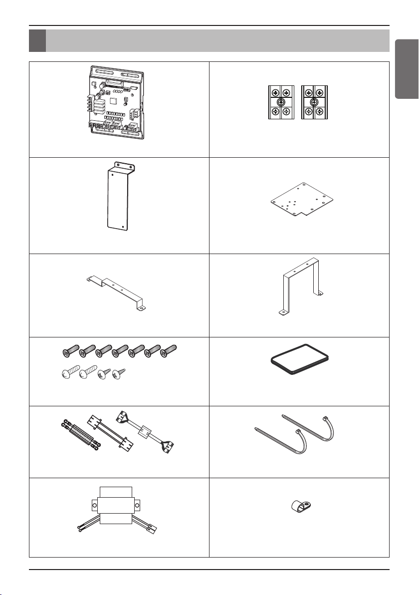
Accessory Parts
IO Module
Terminal Block (2 EA)
Bracket 1
Bracket 2
Bracket 3
Bracket 4
Screw (11 EA)
Manual
Cable (3 EA)
Tie (2 EA)
Transformer
Clamp
Accessory Parts
ENGLISH
Installation manual 5
Page 6
Name of each Part
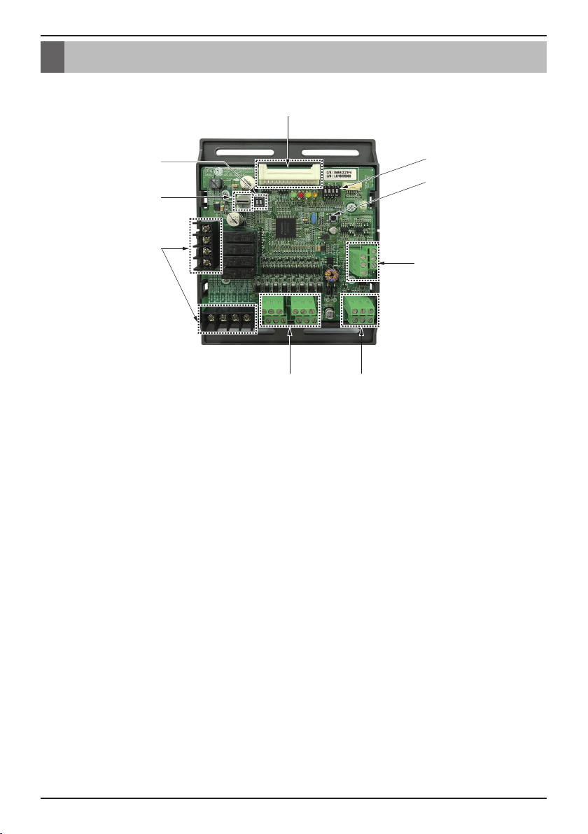
Name of each Part
ڸ
ڹ
ں
ڻ
ڼڽ
① Main connector : Power input and communication connector with Outdoor unit
② SW102 : Switch for setting internal function
③ SW104 : Rotary Switch for setting Demand control step
④ Digital Output : Operating & Error status Relay output (250 V, 1 A)
Reserved Relay output (250 V, 1 A)
⑤ Digital Input : Dry contact input
ۀ
ڿ
ھ
⑥ Analog Input : DC 0 ~ 10 V Analog signal input
⑦ Analog Output : DC 0 ~ 10 V Analog signal output
⑧ SW103 : Reset Switch
⑨ SW101 : DIP Switch for setting operating function
6 Low Ambient Control Kit
Page 7
Installation Method
ڸ
ڹ
ں
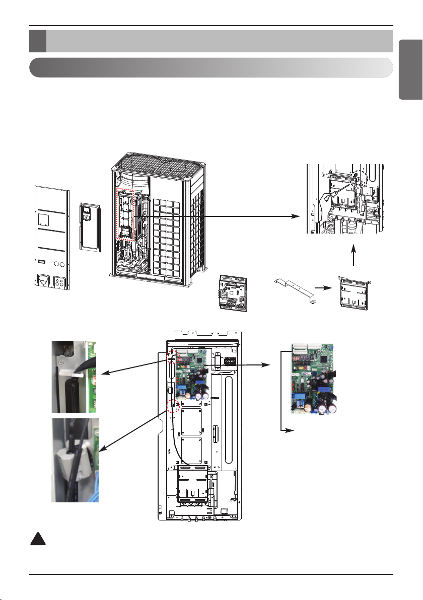
Installation Method
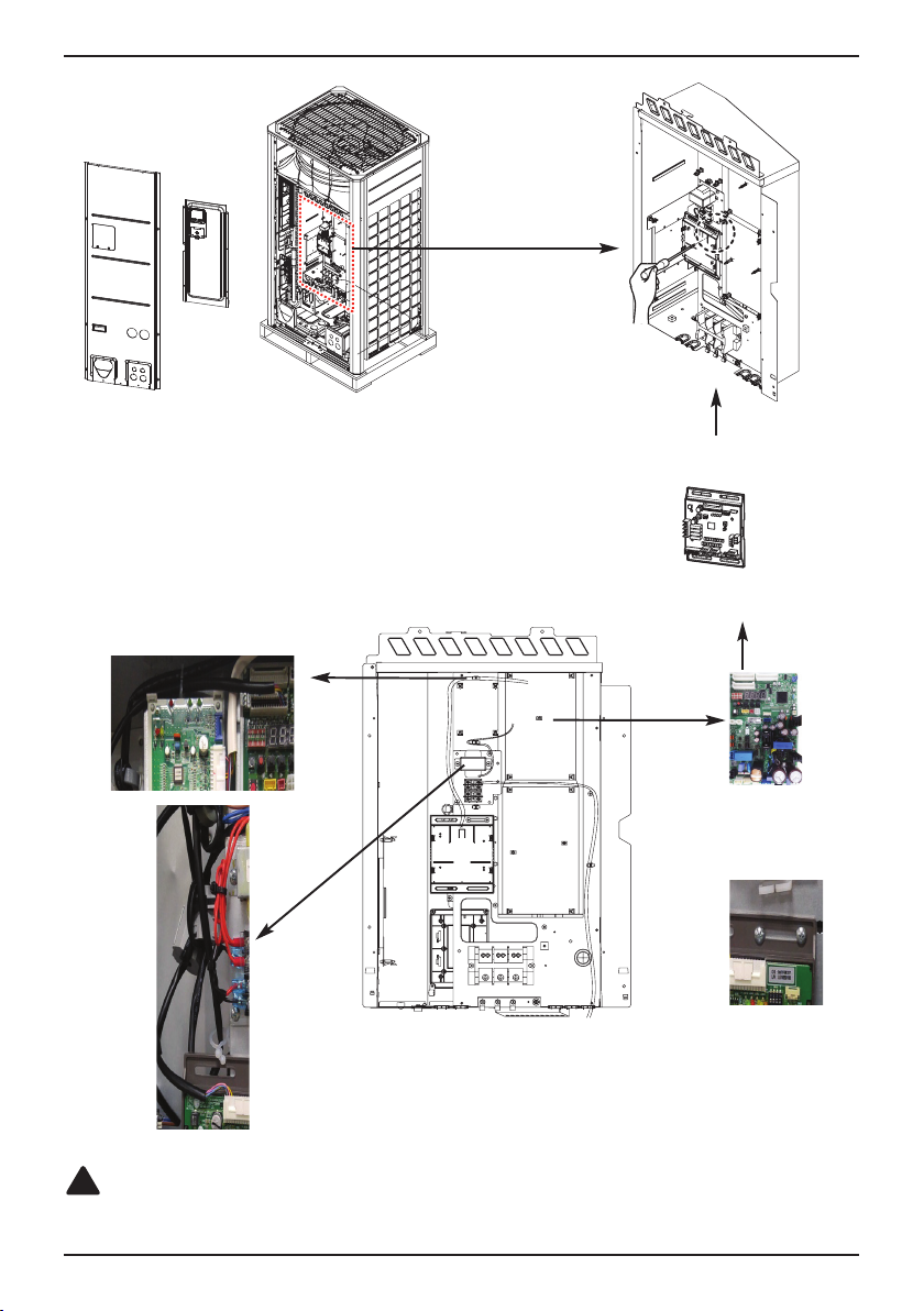
IO Module Installation Method
① Separate front panel from outdoor unit.
② Separate front cover of control box.
③ Assemble IO Module and Bracket3.
Connect the connection wires according to the instructions. (Please refer to Setting and Using Method)
④
UXB
+
ڻ
ENGLISH
!
CAUTION
Be sure to turn off outdoor unit power before installation.
Main board connector
Installation manual 7
Page 8
Installation Method
ڸ
ڹ
ں
ڻ
UXA
Main board connector
!
CAUTION
Be sure to turn off outdoor unit power before installation.
8 Low Ambient Control Kit
Page 9
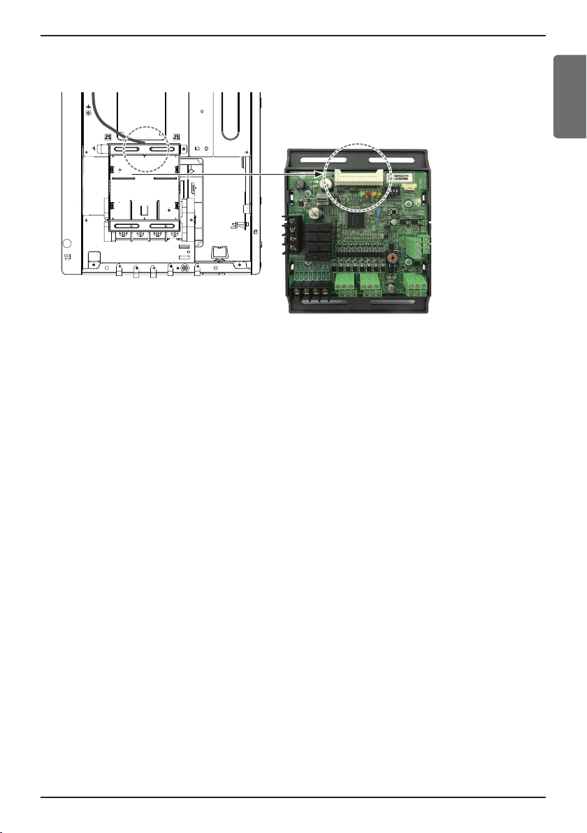
⑤ Fix and fasten components and cables.
⑥ Perform the switch setting according to the instructions.
Installation Method
ENGLISH
Installation manual 9
Page 10
Installation Method
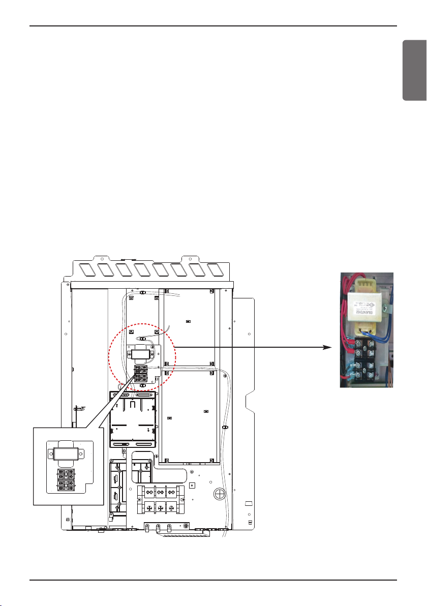
Transformer, Terminal Block Installation Method
UXB
① Shut off the main power of outdoor unit.
② Install the IO Module in the C/Box by using screws.
③ Install the Bracket2 in the C/Box by using screws.
④ Install the transformer on the Bracket2 by using screws.
⑤ Install the terminal block on the Bracket2 by using screws.
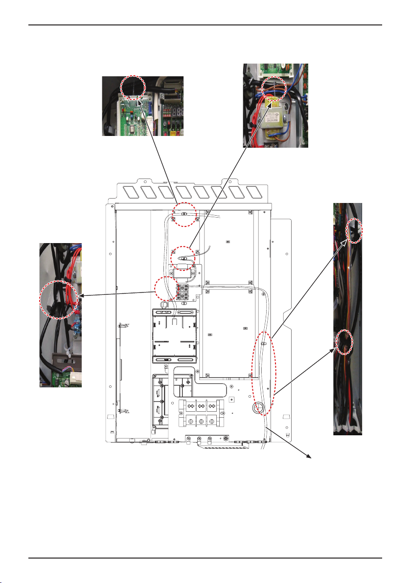
⑥ Connect the Main PCB(CN10) to IO Module(CN101) by using the cable assembly.
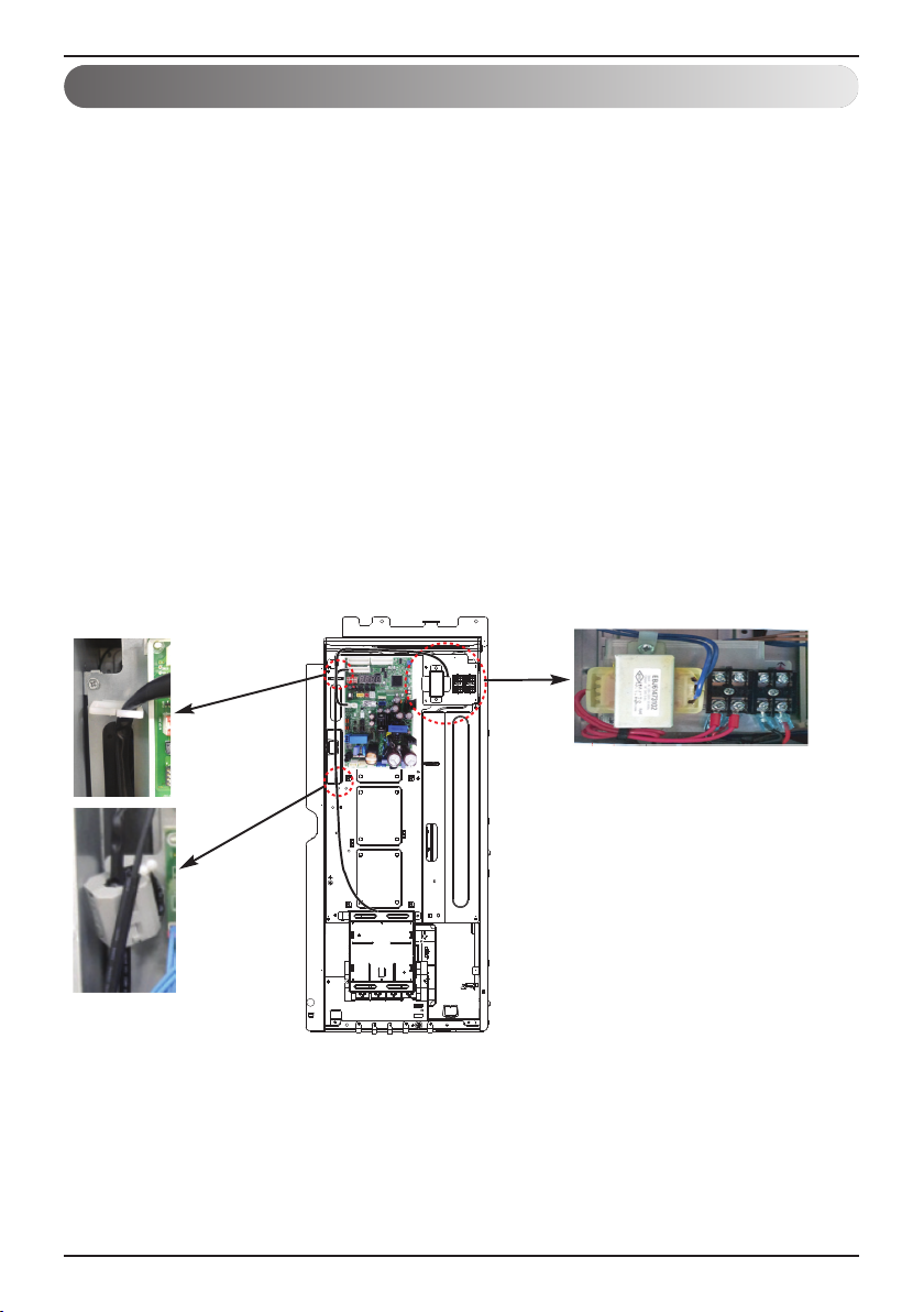
⑦ Connect the blue cable of transformer to the Main PCB(JIG_N), brown cable of transformer to
the Main PCB(JIG_L).
⑧ Connect the red cable of transformer to the terminal block (2Pin Yellow terminal block).
⑨ Connect a power cable(DC 12 V) to CN101(12 V,GND) of IO Module.
⑩ Connect the black cable of Damper Actuator to the terminal block and connect the cable of
IO Module(CN1_A0(GND(A-)) to the black cable of Damper Actuator.
⑪ Connect the red cable of Damper Actuator to CN1_A0(A0_1(A+)) of IO Module.
⑫ Set up the main function DIP S/W of IO Module.
(SW101 : L1,L2=On and L3,L4=Off / SW102 : L1,L2=Off)
⑬ Set up the DIP S/W of Main Outdoor unit PCB. (Refer to page 21 for details)
⑭ Turn on the main power of outdoor unit.
⑮ Check the signal to CN1_A0(AO_01,GND) of IO Module and Air Damper.
10 Low Ambient Control Kit
Page 11
Installation Method
UXA
① Shut off the main power of outdoor unit.
② Install the IO Module in the C/Box by using screws.
③ Install the Bracket2 in the C/Box by using screws.
④ Install the transformer on the Bracket2 by using screws.
⑤ Install the terminal block on the Bracket2 by using screws.
⑥ Connect the Main PCB(CN10) to IO Module(CN101) by using the cable assembly.
⑦ Connect the blue cable of transformer to the Main PCB(JIG_N), brown cable of transformer to
the Main PCB(JIG_L).
⑧ Connect the red cable of transformer to the terminal block (2Pin Yellow terminal block).
⑨ Connect a power cable(DC 12 V) to CN101(12 V,GND) of IO Module.
⑩ Connect the black cable of Damper Actuator to the terminal block and connect the cable of
IO Module(CN1_A0(GND(A-)) to the black cable of Damper Actuator.
⑪ Connect the red cable of Damper Actuator to CN1_A0(A0_1(A+)) of IO Module.
⑫ Set up the main function DIP S/W of IO Module.
(SW101 : L1,L2=On and L3,L4=Off / SW102 : L1,L2=Off)
⑬ Set up the DIP S/W of Main Outdoor unit PCB. (Refer to page 21 for details)
⑭ Turn on the main power of outdoor unit.
⑮ Check the signal to CN1_A0(AO_01,GND) of IO Module and Air Damper.
ENGLISH
Installation manual 11
Page 12
Installation Method
Using the Clamp and Tie, fasten the Damper Actuator output cable and Trans output cable as
below.
12 Low Ambient Control Kit
Actuator Wire
Page 13
Setting and Using Method
Error Status
Input_3
Power
AC or DC
LG does not supply this
section (Field supply)
Status output Relay can
endure 250 VAC, 1 A.
Power
AC or DC
Operating Status
ڻ
ڻ
Reserved
Reserved
Power
AC or DC
Power
AC or DC
Reserved
Input_1Input_2
Input_LNO
Reserved
Input_7
Priority setting
AI_1
Reserved
ڹ
AO_4
AO_4 GND
AO_3 GND
AO_2 GND
AO_1 GND
AO_3
AO_2
AO_1
ں
ڸ
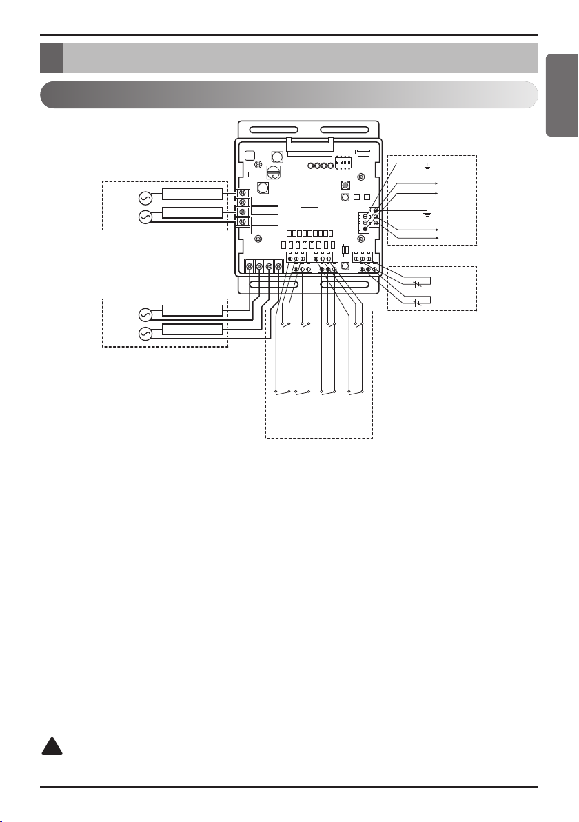
Setting and Using Method
Power source input
AI : Analog Input (DC 0~10 V)
AO : Analog Output ( DC 0~10 V, Max 20 mA)
Input_LNO : Low Noise Operation
ENGLISH
① Dry contact input part
Connect Non Voltage contact signal for demand control (3 step)
* Priority setting
Using ‘Priority setting’ contact signal, set the priority of command.
(External command from DDC Vs Command from LG central controller.)
② Analog input part
- Close : Central controller has priority to external signal.
- Open : External signal has priority to central controller.
Connect Analog input signal for demand control (10 step)
③ Analog output part
Connect Analog output signal for controlling third party devices.
Ex) Valve actuator for variable water flow. Damper actuator for Low Ambient Kit
④ Digital output part
Connect status display devices.
!
CAUTION
Power must be turned on after the product is wired completely.
Installation manual 13
Page 14
Setting and Using Method
n
Communication and Power Line
- If communication and power lines are run alongside each other then there is a strong likelihood of
operational faults developing due to interference in the signal wiring caused by electrostatic and
electromagnetic coupling. The tables below indicates our recommendation as to appropriate spacing
of communication and power lines where these are to be run side by side.
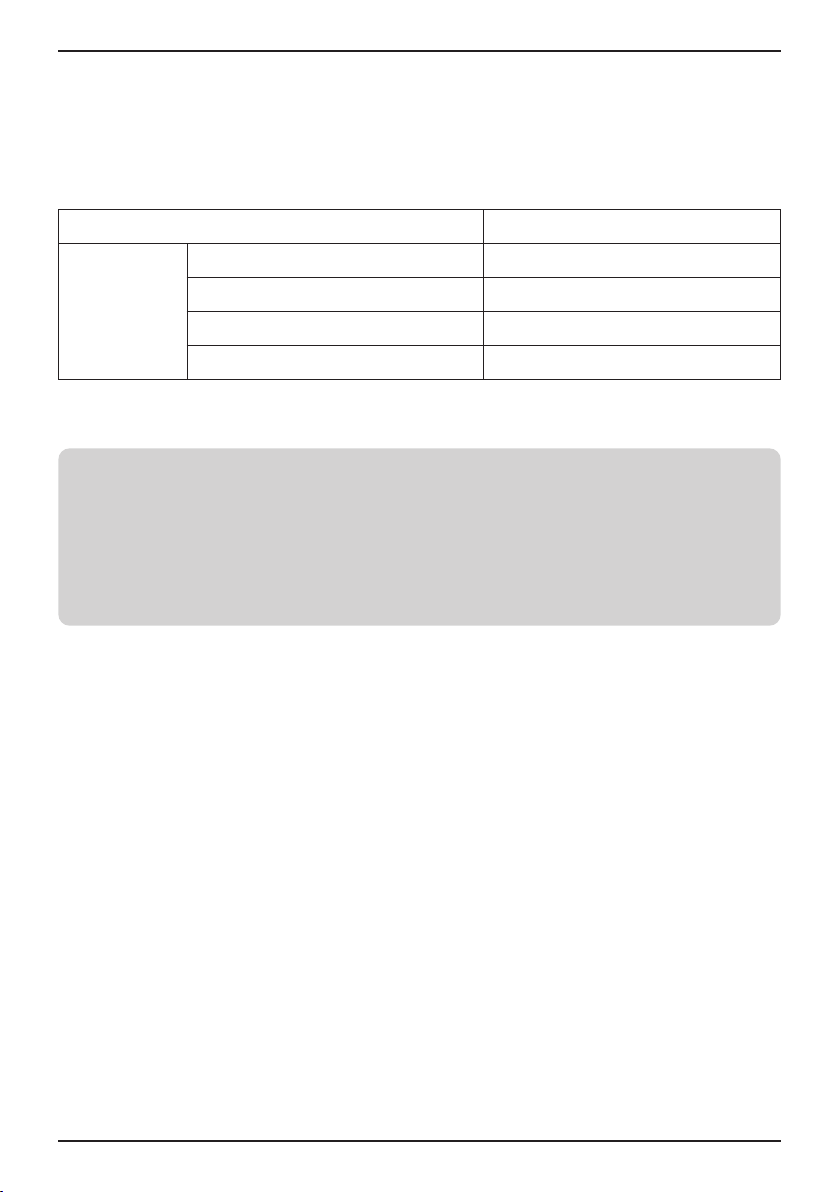
Current capacity of power line Spacing
10 A 11-13/16 in (300 mm)
100 V or more
Notes
If the power supply waveform continues to exhibit some distortion the recommended spacing in the
table should be increased.
• If the lines are laid inside conduits then the following point must also be taken into account when
grouping various lines together for introduction into the conduits.
• Power lines (including power supply to air conditioner) and signal lines must not be laid inside the
same.
• In the same way, when grouping the lines power and signal lines should not be bunched together.
50 A 19-11/16 in (500 mm)
100 A 39-3/8 in (1 000 mm)
Exceed 100 A 59-3/64 in (1 500 mm)
14 Low Ambient Control Kit
Page 15
Setting and Using Method
SW102 SW101
L1
ON
2
3
4
L1
ON
2
ON
L1 2 3 4
ON
L1 2
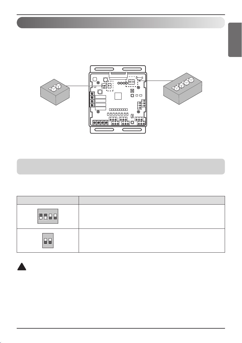
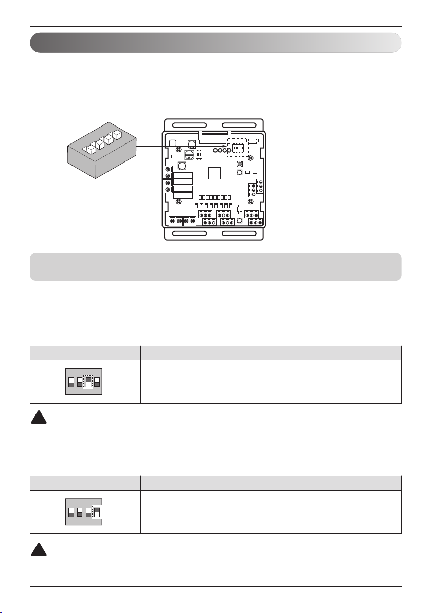
IO Module - Low Ambient Kit Function
Setting of DIP Switch
Using ‘SW101’, ‘SW102’, You can use Low Ambient Kit Mode
Notes
Default status is all off.
Set Low Ambient Kit Operation
ENGLISH
Position Setting of DIP Switch
SW101 - L1=ON
SW102 - L1=OFF
!
CAUTION
•
If the DIP SW is set , IO module System is operating preferentially than outdoor unit setting.
• After change DIP SW setting, press reset switch to reflect the setting.
L2=ON
L3=OFF
L4=OFF
L2=OFF
Installation manual 15
Page 16
Setting and Using Method
L1
ON
2
3
4
ON
L1 2 3 4
ON
L1 2 3 4
IO Module - Other Function
Setting of DIP Switch
Using ‘SW101’, select the option of control function as described below.
Notes
Default status is all off.
• L3 : Set Low Noise Operation
This is a function driving outdoor unit fan RPM to operate low speed for reducing fan noise
according to the input signal. To use this function, you should set Outdoor unit mode, Please
refer to PDB more detail.
Position Function
ON : Enable Low Noise Operation
OFF : Disable Low Noise Operation
!
CAUTION
If the DIP SW is set , IO module System is operating preferentially than outdoor unit setting.
• L4 : Set Operating status output
Position Function
!
CAUTION
After change DIP SW setting, press reset switch to reflect the setting.
16 Low Ambient Control Kit
ON : Activate Digital Output according to Indoor Unit status
OFF : Activate Digital Output according to Outdoor Unit status
Page 17
Setting and Using Method
L1
ON
2
ON
L1 2
ON
L1 2
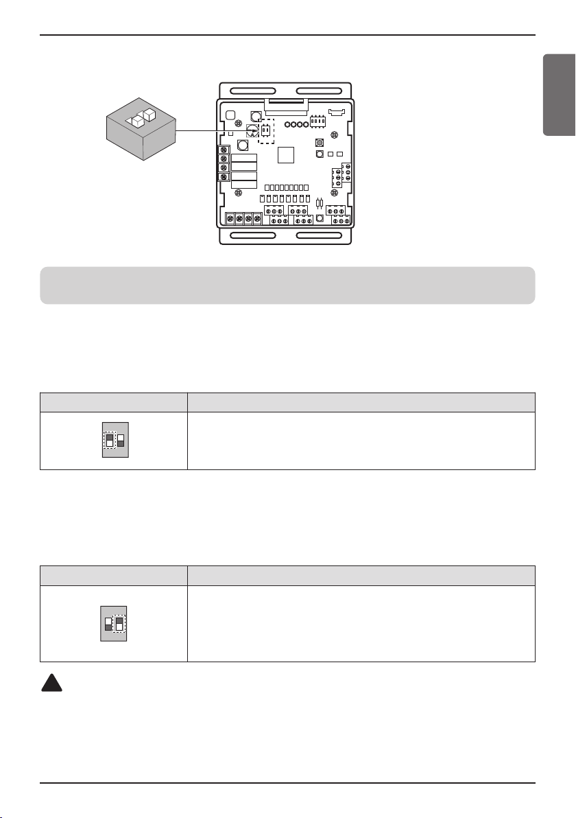
Using ‘SW102’, set the internal function as described below.
Notes
Default status is all off.
• L1 : Set Analog output default value when Communication Error will be occur (Module – ODU)
Position Function
ENGLISH
ON : Analog output 0 V
OFF : Analog output 10 V
• L2 : Set Analog output Range
Basically this module keeps a minimum Analog output voltage refer to L1,L2 setting of SW101 to
prevent unexpected accident. When you need to use 0~10V full range, L2 should be set as ON.
Position Function
ON : Ignore minimum Analog output value setting
(L1,L2 setting value of 4pin DIP SW)
OFF : Follow minimum Analog output value setting
(L1,L2 setting value of 4pin DIP SW)
!
CAUTION
After change DIP SW setting, press reset switch to reflect the setting.
Installation manual 17
Page 18
Setting and Using Method
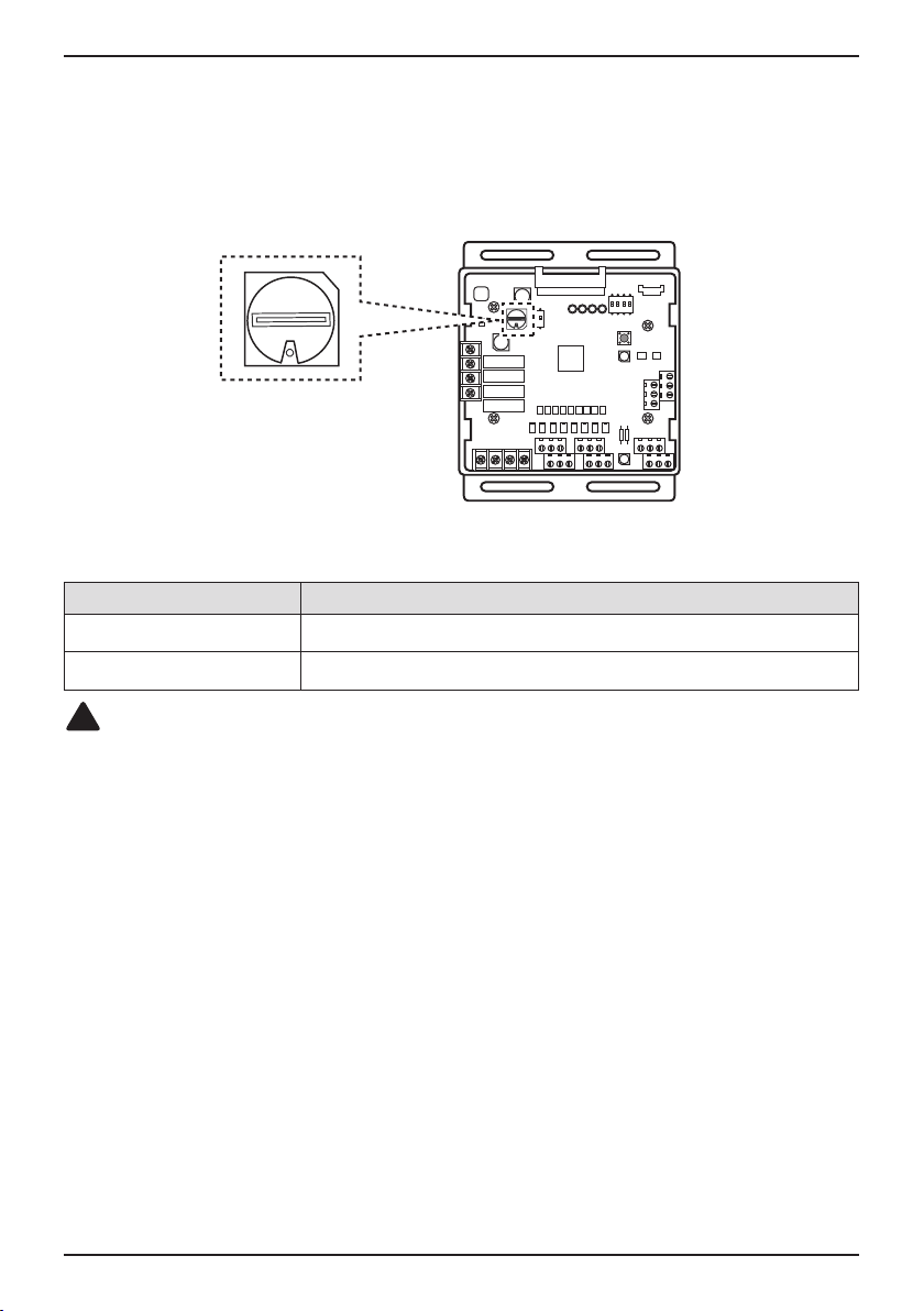
Setting of Rotary Switch
Use the Rotary Switch to set a control step for contact signal input : The type of input signal and
control step can be set using ‘SW104’
This function is for demand control to reduce power consumption.
Set the control mode what you want according to the table as below.
- Type of input signal
SW_STEP
0, 1, 2, 3, 4, 5, 6, 7 Contact signal input
C, D, E Analog input signal
!
CAUTION
Do not change a command too quickly.
Keep the command 30 seconds at least, otherwise it will cause a damage to outdoor unit.
• Operation rate condition :
- Cooling : Outdoor 35 °C, Indoor 27 °C
- Heating : Outdoor 7 °C, Indoor 20 °C
• The tolerance of the operation rate can be cause by combination of outdoor unit, operating
condition, installation circumstance.
• When operation rate is 100 %, Target Evaporating Temp. and Target Condensing Temp. can be
changed by installation option. (Refer to product data book)
• Input_1 : 0 Έ OFF, Input_1 : 1 Έ ON
Input signal
18 Low Ambient Control Kit
Page 19

Setting and Using Method
Wiring for Damper Actuator
1 Unit
BRBL
AC 220 V
Transformer
RD
RD
Terminal
Block
IO Module
Damper
Actuator
ENGLISH
WH
GR
BK
RD
AC/DC 24 V
h BL : Blue, BR : Brown, RD : Red, BK : Black, WH : White, GR : Green
Notes
Damper Actuator can accept only DC 24 V power input.
Do not input AC power. Otherwise it will cause a serious damage.
The IO Module can control maximum three actuators.
Case of one valve, the slave signal connector must not use.
The power (AC/DC 24 V) and signal(DC 0~10 V) line is recommended by AWG22(1/32 in, (0.644 mm),
0.016 Ω/ft (0.053 Ω/m)).
DC 0~10 V
Control Signal
Installation manual 19
Page 20

Setting and Using Method
2 Unit
BL BR
Transformer
RD
RD
BK
AC 220 V
RD
Terminal
Block
IO Module
GR
GR
BK
RD
BK
RD
Damper
Actuator
WH
Damper
Actuator
WH
Notes
Damper Actuator can accept only DC 24 V power input.
Do not input AC power. Otherwise it will cause a serious damage.
The IO Module can control maximum three actuators.
Case of one valve, the slave signal connecter must not use.
The power (AC/DC 24 V) and signal(DC 0~10 V) line is recommended by AWG22(1/32 in, (0.644 mm),
0.016 Ω/ft (0.053 Ω/m)).
20 Low Ambient Control Kit
Page 21

Setting and Using Method
3 Unit
Transformer
RD
RD
BK
AC 220 V
RD
Terminal
Block
IO Module
GR
GR
GR
BK
RD
BK
RD
Damper
Actuator
WH
BK
RD
Damper
Actuator
WH
Damper
Actuator
WH
ENGLISH
Notes
Damper Actuator can accept only DC 24 V power input.
Do not input AC power. Otherwise it will cause a serious damage.
The IO Module can control maximum three actuators.
Case of one valve, the slave signal connecter must not use.
The power (AC/DC 24 V) and signal(DC 0~10 V) line is recommended by AWG22(1/32 in, (0.644 mm),
0.016 Ω/ft (0.053 Ω/m)).
Installation manual 21
Page 22

Setting and Using Method
Setting of Outdoor Unit DIP Switch
Low Ambient Kit Mode
• Low Ambient Kit mode Setting method
Master unit PCB DIP switch on : No.5
Select the mode using ‘▶’, ‘◀’ Button :
“Func” Push the '●' (Confirm) button
Select the Function using ‘▶’, ‘◀’ Button :
DIP SWITCH 7-Segment
“Fn9” Push the '●' (Confirm) button
Select the Function using ‘▶’, ‘◀’ Button :
“On” Push the '●' (Confirm) button
Low Ambient Kit mode is set
h If you want to stop the Low Ambient Kit mode, refer to the following.
▷ DIP Switch No.5 On -> “Func” -> “Fn9” -> “Off”
SW04C ( X : cancel)
SW03C (
SW02C ( : backward)
SW01C ( : confirm)
SW01D (reset)
: forward)
ȯ
ȭ
Ɨ
22 Low Ambient Control Kit
Page 23

Installation Method of Snow Hood and Air Damper
Installation Method of Snow Hood and Air Damper
ENGLISH
One Unit with Snow Hood and Air Damper
One Unit with Snow Hood and Air Damper
Installation manual 23
Page 24

Installation Method of Snow Hood and Air Damper
Two and Three Units with Snow Hood and Air Damper
Two Units with Snow Hood and Air Damper
Three Units with Snow Hood and Air Damper
24 Low Ambient Control Kit
Page 25

Installation Method of Snow Hood and Air Damper
Top View
Prevailing wind
Building Wall
Outdoor Unit
H ≤ discharge
of air damper
Unit Placement and Clearances
1. Outdoor units should be located in an area protected from prevailing winds. (shown below)
In high wind locations it may be advisable to locate the units within a walled area.
2. If the units are surrounded by an enclosure, the discharge of the air damper must direct the air out and over the
enclosure walls to prevent air recirculation.
ENGLISH
Installation manual 25
Page 26

Installation Method of Snow Hood and Air Damper
3. When the distance is less than 7-7/8 in(200 mm) between outdoor units, do not necessary installation of side
Snow Hood as below.
7-7/8 in(200 mm)
26 Low Ambient Control Kit
7-7/8 in(200 mm)7-7/8 in(200 mm)
Page 27

Installation Method of Snow Hood and Air Damper
4. If units are placed further than 7-7/8 in(200 mm) apart, additional snow hoods may be required.
ENGLISH
Installation manual 27
Page 28

28 Low Ambient Control Kit
Page 29

ENGLISH
Installation manual 29
Page 30

30 Low Ambient Control Kit
Page 31

ENGLISH
Installation manual 31
Page 32

Representative (EU Only): LG Electronics Inc. EU Representative, Krijgsman 1, 1186 DM
Manufacturer: LG Electronics Inc. Changwon 2nd factory 84, Wanam-ro, Seongsan-gu,
Changwon-si, Gyeongsangnam-do, KOREA
Amstelveen, The Netherlands
Page 33

❈ PRVC2 is available only for the Multi-V IV model
(PRVC2 can not be installed for the previous Multi-V IV model)
INSTALLATION MANUAL
Low Ambient
Control Kit
www.lg.com
PRVC2
Please read this installation manual completely before installing the product.
Installation work must be performed in accordance with the national wiring
standards by authorized personnel only.
Please retain this installation manual for future reference after reading it
thoroughly.
MFL42540235
Rev.00_010319
Original instruction
Copyright © 2013 - 2018 LG Electronics Inc. All Rights Reserved.
ENGLISH
Page 34

Table of contents
TABLE OF CONTENTS
3 SAFETY PRECAUTIONS
5 ACCESSORY PARTS
6 NAME OF EACH PART
7 INSTALLATION METHOD
7 IO Module Installation Method
9 Transformer, Terminal Block Installation Method
11 SETTING AND USING METHOD
11 Power source input
13 IO Module – Low Ambient Kit Function
14 IO Module – Other Function
17 Wiring for Damper Actuator
20 Setting of Outdoor Unit DIP Switch
21 INSTALLATION METHOD OF SNOW HOOD AND AIR
DAMPER
21 One Unit with Snow Hood and Air Damper
22 Two and Three Units with Snow Hood and Air Damper
23 Unit Placement and Clearances
2 Low Ambient Control Kit
Page 35

Safety Precautions
Safety Precautions
To prevent injury to the user or other people and property damage, the following instructions
must be followed.
n Incorrect operation due to ignoring instruction will cause harm or damage. The seriousness is
classified by the following indications.
ENGLISH
!
WARNING
!
CAUTION
n Meanings of symbols used in this manual are as shown below.
This symbol indicates the possibility of death or serious injury.
This symbol indicates the possibility of injury or damage.
Be sure not to do.
Be sure to follow the instruction.
!
WARNING
Installation
• Don’t touch with the hands while the power is on.
- Cause fire, electric shock, explosion or injury.
• Product installation must be referred to a service center or installation shop.
- Cause fire, electric shock, explosion or injury.
• Request installation from installation shop or service center when reinstalling the product.
- Cause fire, electric shock, explosion or injury.
• Do not install the product in the place where rain can get to the product.
- Cause product failure
• Do not install the unit in humid locations.
- Cause product failure
• Do not put the product closer to fire.
- Cause fire
• Do not install in a place that cannot withstand the weight of the product.
- The product may get damaged or may break.
• Do not install the product to a place that generates oil, steam, salt, sulfuric gas, etc.
- Cause the product’s deformation or failure.
• Use standardized Product.
- Cause product failure
Operation
• Do not change or extend power lines arbitrarily.
- Cause fire or electric shock.
• Do not give a shock to the product.
- If you give a shock to the product, it may cause the product’s failure.
Installation manual 3
Page 36

Safety Precautions
• Do not use a heater near the power line.
- Cause fire or electric shock.
• Do notspill water inside of the product.
- Cause electric shock or breakdown.
• If the product has been inundated, you must refer to a service center or installation shop.
- It can cause a fire.
• Children and elderly use the product under the guardian’s supervision.
- Cause accidents and product failures.
• Do not use for special purpose / place such as conserving flora and fauna, precision instruments, art.
- Otherwise, it can cause property damage.
• Remove the power plug when cleaning.
- Cause fire or electric shock.
• Do not place heavy objects on the power line.
- Cause fire or electric shock.
• Do not disassemble, repair, or modify the product.
- Cause fire or electric shock.
• Do not touch with wet hands.
- Cause fire or electric shock.
4 Low Ambient Control Kit
Page 37

Accessory Parts
IO Module
Terminal Block (2 EA)
Bracket 1
Bracket 2
Bracket 3
Bracket 4
Screw (11 EA)
Manual
Cable (3 EA)
Tie (2 EA)
Transformer
Clamp
Accessory Parts
ENGLISH
Installation manual 5
Page 38

Name of each Part
Name of each Part
ڸ
ڹ
ں
ڻ
ڼڽ
① Main connector : Power input and communication connector with Outdoor unit
② SW102 : Switch for setting internal function
③ SW104 : Rotary Switch for setting Demand control step
④ Digital Output : Operating & Error status Relay output (250 V, 1 A)
Reserved Relay output (250 V, 1 A)
⑤ Digital Input : Dry contact input
ۀ
ڿ
ھ
⑥ Analog Input : DC 0 ~ 10 V Analog signal input
⑦ Analog Output : DC 0 ~ 10 V Analog signal output
⑧ SW103 : Reset Switch
⑨ SW101 : DIP Switch for setting operating function
6 Low Ambient Control Kit
Page 39

Installation Method
ڸ
ڹ
ں
Installation Method
IO Module Installation Method
① Separate front panel from outdoor unit.
② Separate front cover of control box.
③ Assemble IO Module and bracket.
Connect the connection wires according to the instructions. (Please refer to Setting and Using Method)
④
+
ENGLISH
Main board connector
!
CAUTION
Be sure to turn off outdoor unit power before installation.
ڻ
Installation manual 7
Page 40

Installation Method
⑤ Fix and fasten components and cables.
⑥ Perform the switch setting according to the instructions.
8 Low Ambient Control Kit
Page 41

Installation Method
+
+
Transformer
Clamp
Bracket 2 and
Bracket 4
Terminal Block
Transformer, Terminal Block Installation Method
① Shut off the main power of outdoor unit.
② Install the IO Module in the C/Box by using screws.
③ Install the Bracket2 in the C/Box by using screws.
④ Install the transformer on the Bracket2 by using screws.
⑤ Install the terminal block on the Bracket2 by using screws.
⑥ Connect the Main PCB(CN10) to IO Module(CN101) by using the cable assembly.
⑦ Connect the blue cable of transformer to the Main PCB(JIG_N), brown cable of transformer to
the Main PCB(JIG_L).
⑧ Connect the red cable of transformer to the terminal block (2Pin Yellow terminal block).
⑨ Connect a power cable(DC 12 V) to CN101(12 V,GND) of IO Module.
⑩ Connect the black cable of Damper Actuator to the terminal block and connect the cable of
IO Module(CN1_A0(GND(A-)) to the black cable of Damper Actuator.
⑪ Connect the red cable of Damper Actuator to CN1_A0(A0_1(A+)) of IO Module.
⑫ Set up the main function DIP S/W of IO Module.
(SW101 : L1,L2=On and L3,L4=Off / SW102 : L1,L2=Off)
⑬ Set up the DIP S/W of Main Outdoor unit PCB. (Refer to page 21 for details)
⑭ Turn on the main power of outdoor unit.
⑮ Check the signal to CN1_A0(AO_01,GND) of IO Module and Air Damper.
ENGLISH
Installation manual 9
Page 42

Installation Method
Actuator Wire
Using the Clamp and Tie, fasten the Damper Actuator output cable and Trans output cable as
below.
10 Low Ambient Control Kit
Page 43

Setting and Using Method
Power source input
Setting and Using Method
ENGLISH
LG does not supply this
section (Field supply)
Power
AC or DC
ڻ
Power
AC or DC
Status output Relay can
endure 250 VAC, 1 A.
Power
AC or DC
ڻ
Power
AC or DC
Error Status
Operating Status
Reserved
Reserved
ڸ
Input_LNO
Input_1Input_2
Input_3
Reserved
Priority setting
Reserved
Input_7
AI : Analog Input (DC 0 ~ 10 V)
AO : Analog Output ( DC 0 ~ 10 V, Max 20 mA)
Input_LNO : Low Noise Operation
① Dry contact input part
Connect Non Voltage contact signal for demand control (3 step)
* Priority setting
Using ‘Priority setting’ contact signal, set the priority of command.
(External command from DDC Vs Command from LG central controller.)
- Close : Central controller has priority to external signal.
- Open : External signal has priority to central controller.
② Analog input part
Connect Analog input signal for demand control (10 step)
③ Analog output part
Connect Analog output signal for controlling third party devices.
Ex) Valve actuator for variable water flow. Damper actuator for Low Ambient Kit
④ Digital output part
Connect status display devices.
AO_4 GND
AO_3 GND
AO_4
AO_3
AO_2 GND
AO_1 GND
AO_2
AO_1
Reserved
AI_1
ں
ڹ
!
CAUTION
Power must be turned on after the product is wired completely.
Installation manual 11
Page 44

Setting and Using Method
n
Communication and Power Line
- If communication and power lines are run alongside each other then there is a strong likelihood of
operational faults developing due to interference in the signal wiring caused by electrostatic and
electromagnetic coupling. The tables below indicates our recommendation as to appropriate spacing
of communication and power lines where these are to be run side by side.
Current capacity of power line Spacing
10 A 11-13/16 in (300 mm)
100 V or more
Notes
If the power supply waveform continues to exhibit some distortion the recommended spacing in the
table should be increased.
• If the lines are laid inside conduits then the following point must also be taken into account when
grouping various lines together for introduction into the conduits.
• Power lines (including power supply to air conditioner) and signal lines must not be laid inside the
same.
• In the same way, when grouping the lines power and signal lines should not be bunched together.
50 A 19-11/16 in (500 mm)
100 A 39-3/8 in (1 000 mm)
Exceed 100 A 59-3/64 in (1 500 mm)
12 Low Ambient Control Kit
Page 45

Setting and Using Method
ON
L1 2 3 4
ON
L1 2
IO Module – Low Ambient Kit Function
Setting of DIP Switch
Using ‘SW101’, ‘SW102’, You can use Low Ambient Kit Mode
ON
ON
4
3
2
L1
2
L1
ENGLISH
Notes
Default status is all off.
Set Low Ambient Kit Operation
Position Setting of DIP Switch
SW101 - L1=ON
SW102 - L1=OFF
!
CAUTION
•
If the DIP SW is set , IO module System is operating preferentially than outdoor unit setting.
• After change DIP SW setting, press reset switch to reflect the setting.
L2=ON
L3=OFF
L4=OFF
L2=OFF
Installation manual 13
Page 46

Setting and Using Method
ON
L1 2 3 4
ON
L1 2 3 4
IO Module – Other Function
Setting of DIP Switch
Using ‘SW101’, select the option of control function as described below.
ON
Notes
Default status is all off.
• L3 : Set Low Noise Operation
This is a function driving outdoor unit fan RPM to operate low speed for reducing fan noise
according to the input signal. To use this function, you should set Outdoor unit mode, Please
refer to PDB more detail.
Position Function
!
CAUTION
If the DIP SW is set , IO module System is operating preferentially than outdoor unit setting.
4
3
2
L1
ON : Enable Low Noise Operation
OFF : Disable Low Noise Operation
• L4 : Set Operating status output
Position Function
ON : Activate Digital Output according to Indoor Unit status
OFF : Activate Digital Output according to Outdoor Unit status
!
CAUTION
After change DIP SW setting, press reset switch to reflect the setting.
14 Low Ambient Control Kit
Page 47

Setting and Using Method
ON
L1 2
ON
L1 2
Using ‘SW102’, set the internal function as described below.
ON
2
L1
Notes
Default status is all off.
• L1 : Set Analog output default value when Communication Error will be occur (Module – ODU)
Position Function
ON : Analog output 0 V
OFF : Analog output 10 V
ENGLISH
• L2 : Set Analog output Range
Basically this module keeps a minimum Analog output voltage refer to L1,L2 setting of SW101 to
prevent unexpected accident. When you need to use 0~10 V full range, L2 should be set as ON.
Position Function
ON : Ignore minimum Analog output value setting
(L1,L2 setting value of 4pin DIP SW)
OFF : Follow minimum Analog output value setting
(L1,L2 setting value of 4pin DIP SW)
!
CAUTION
After change DIP SW setting, press reset switch to reflect the setting.
Installation manual 15
Page 48

Setting and Using Method
Setting of Rotary Switch
Use the Rotary Switch to set a control step for contact signal input : The type of input signal and
control step can be set using ‘SW104’
This function is for demand control to reduce power consumption.
Set the control mode what you want according to the table as below.
- Type of input signal
SW_STEP
0, 1, 2, 3, 4, 5, 6, 7 Contact signal input
C, D, E Analog input signal
!
CAUTION
Do not change a command too quickly.
Keep the command 30 seconds at least, otherwise it will cause a damage to outdoor unit.
• Operation rate condition :
- Cooling : Outdoor 35 °C, Indoor 27 °C
- Heating : Outdoor 7 °C, Indoor 20 °C
• The tolerance of the operation rate can be cause by combination of outdoor unit, operating
condition, installation circumstance.
• When operation rate is 100 %, Target Evaporating Temp. and Target Condensing Temp. can be
changed by installation option. (Refer to product data book)
• Input_1 : 0 Έ OFF, Input_1 : 1 Έ ON
Input signal
16 Low Ambient Control Kit
Page 49

Setting and Using Method
Wiring for Damper Actuator
1 Unit
Transformer
RD
AC 220 V
RD
Terminal
Block
BL
BR
IO Module
Main PCB Power Module
Damper
Actuator
ENGLISH
WH
GR
BK
RD
AC/DC 24 V
DC 0~10 V
Control Signal
h BL : Blue, BR : Brown, RD : Red, BK : Black, WH : White, GR : Green
Notes
Damper Actuator can accept only DC 24 V power input.
Do not input AC power. Otherwise it will cause a serious damage.
The IO Module can control maximum three actuators.
Case of one valve, the slave signal connector must not use.
The power (AC/DC 24 V) and signal(DC 0~10 V) line is recommended by AWG22(1/32 in, (0.644 mm),
0.016 Ω/ft (0.053 Ω/m)).
Installation manual 17
Page 50

Setting and Using Method
2 Unit
BL
Main PCB Power Module
BR
Transformer
RD
RD
BK
AC 220 V
RD
Terminal
Block
IO Module
GR
GR
BK
RD
BK
RD
Damper
Actuator
WH
Damper
Actuator
WH
Notes
Damper Actuator can accept only DC 24 V power input.
Do not input AC power. Otherwise it will cause a serious damage.
The IO Module can control maximum three actuators.
Case of one valve, the slave signal connecter must not use.
The power (AC/DC 24 V) and signal(DC 0~10 V) line is recommended by AWG22(1/32 in, (0.644 mm),
0.016 Ω/ft (0.053 Ω/m)).
18 Low Ambient Control Kit
Page 51

Setting and Using Method
3 Unit
Transformer
RD
RD
BK
BL
AC 220 V
RD
Terminal
Block
BR
IO Module
GR
GR
GR
BK
RD
BK
RD
Main PCB Power Module
Damper
Actuator
WH
BK
RD
Damper
Actuator
WH
Damper
Actuator
WH
ENGLISH
Notes
Damper Actuator can accept only DC 24 V power input.
Do not input AC power. Otherwise it will cause a serious damage.
The IO Module can control maximum three actuators.
Case of one valve, the slave signal connecter must not use.
The power (AC/DC 24 V) and signal(DC 0~10 V) line is recommended by AWG22(1/32 in, (0.644 mm),
0.016 Ω/ft (0.053 Ω/m)).
Installation manual 19
Page 52

Setting and Using Method
Setting of Outdoor Unit DIP Switch
Low Ambient Kit Mode
• Low Ambient Kit mode Setting method
Master unit PCB DIP switch on : No.5
Select the mode using ‘▶’, ‘◀’ Button :
“Func” Push the '●' (Confirm) button
Select the Function using ‘▶’, ‘◀’ Button :
DIP SWITCH 7-Segment
“Fn10 or Fn11” Push the '●' (Confirm) button
Select the Function using ‘▶’, ‘◀’ Button :
“On” Push the '●' (Confirm) button
Low Ambient Kit mode is set
h If you want to stop the Low Ambient Kit mode, refer to the following.
▷ DIP Switch No.5 On -> “Func” -> “Fn10” -> “Off”
h Fn10 Model : ARUB***BTE4
ARUB***DTE4
ARUB***LTE4
Fn11 Model : ARUN***BTE4
ARUN***DTE4
ARUN***LTE4
ARUN***LTS4
SW04C ( X : cancel)
SW03C (
SW02C ( : backward)
SW01C ( : confirm)
SW01D (reset)
: forward)
ȯ
ȭ
Ɨ
20 Low Ambient Control Kit
Page 53

Installation Method of Snow Hood and Air Damper
ENGLISH
Installation Method of Snow Hood and Air Damper
One Unit with Snow Hood and Air Damper
One Unit with Snow Hood and Air Damper
Installation manual 21
Page 54

Installation Method of Snow Hood and Air Damper
Two and Three Units with Snow Hood and Air Damper
Two Units with Snow Hood and Air Damper
Three Units with Snow Hood and Air Damper
22 Low Ambient Control Kit
Page 55

Installation Method of Snow Hood and Air Damper
Top View
Prevailing wind
Building Wall
Outdoor Unit
H ≤ discharge
of air damper
Unit Placement and Clearances
1. Outdoor units should be located in an area protected from prevailing winds. (shown below)
In high wind locations it may be advisable to locate the units within a walled area.
ENGLISH
2. If the units are surrounded by an enclosure, the discharge of the air damper must direct the air out and over the
enclosure walls to prevent air recirculation.
Installation manual 23
Page 56

Installation Method of Snow Hood and Air Damper
3. When the distance is less than 7-7/8 in(200 mm) between outdoor units, do not necessary installation of side
Snow Hood as below.
7-7/8 in(200 mm)
7-7/8 in(200 mm)7-7/8 in(200 mm)
24 Low Ambient Control Kit
Page 57

Installation Method of Snow Hood and Air Damper
4. If units are placed further than 7-7/8 in(200 mm) apart, additional snow hoods may be required.
ENGLISH
Installation manual 25
Page 58

26 Low Ambient Control Kit
Page 59

ENGLISH
Installation manual 27
Page 60

Representative: LG Electronics Inc. EU Representative, Krijgsman 1, 1186 DM
Manufacturer: LG Electronics Inc. Changwon 2nd factory, 84, Wanam-ro,
Amstelveen, The Netherlands
Seongsan-gu, Changwon-si, Gyeongsangnam-do, KOREA
 Loading...